Acura CSX. Manual - part 512
−
−
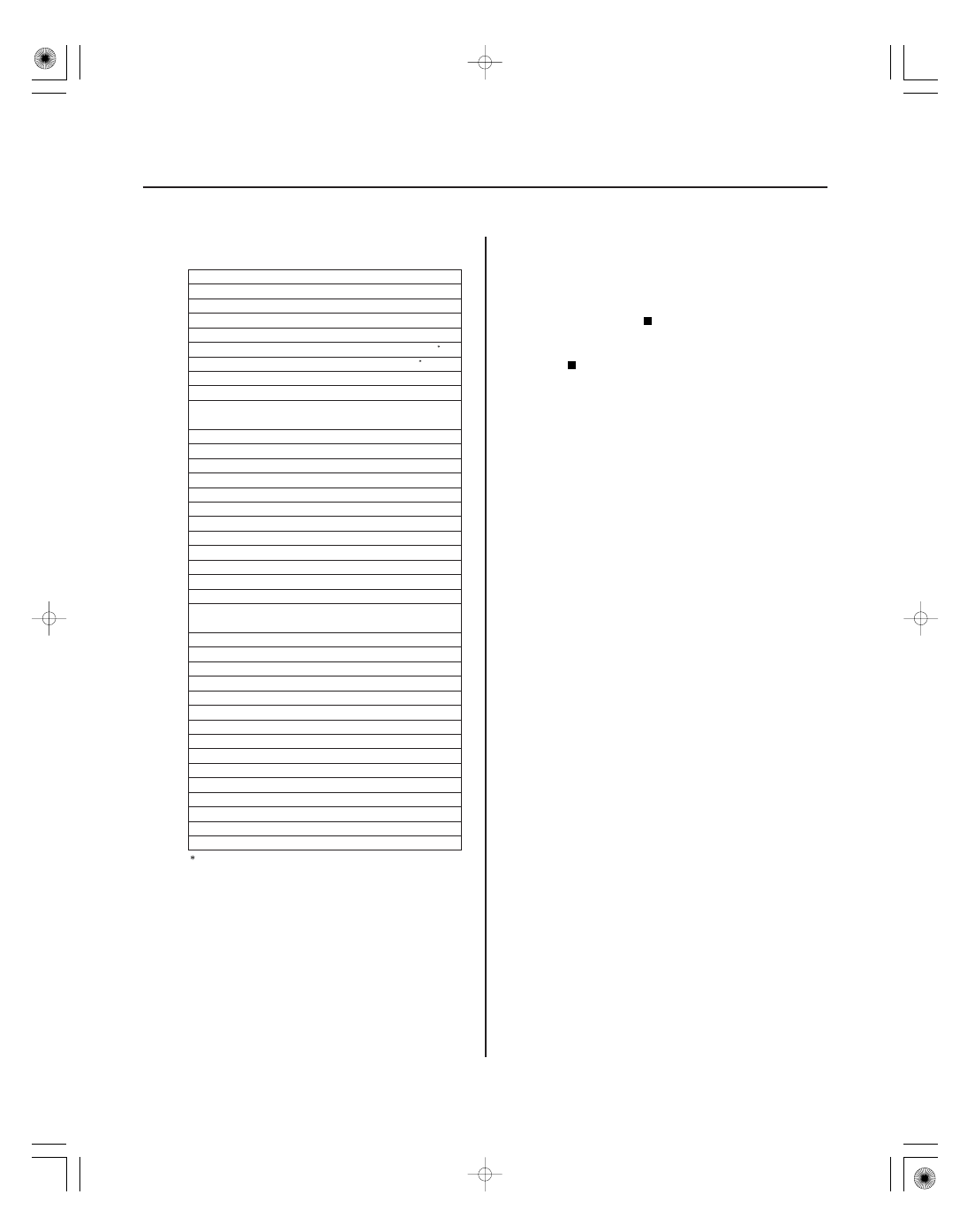
MICU
Item
YES
NO
22-98
Multiplex Integrated Control System
Driver’s door lock switch (UNLOCK)
Driver’s door lock switch (LOCK)
Driver’s door lock knob switch (UNLOCK)
Driver’s door lock knob switch (LOCK)
Driver’s door key cylinder switch (UNLOCK)
Driver’s door key cylinder switch (LOCK)
Front passenger’s door lock switch (UNLOCK)
Front passenger’s door lock switch (LOCK)
Front passenger’s door lock knob switch
(UNLOCK)
Left rear door lock knob switch (UNLOCK)
Right rear door lock knob switch (UNLOCK)
Driver’s door switch (OPEN)
Front passenger’s door switch (OPEN)
Left rear door switch (OPEN)
Right rear door switch (OPEN)
Trunk lid latch switch (OPEN)
Audio switch
Windshield wiper HI/LO switch
Windshield wiper INT/LO switch
Windshield wiper MIST switch
Windshield washer switch (ON)
Windshield wiper intermittent dwell time
controller
Windshield wiper motor park switch
Turn signal switch (LEFT)
Turn signal switch (RIGHT)
Hazard warning switch (ON)
Headlight switch (ON)
Headlight switch (OFF)
Lighting switch (ON)
Dimmer switch (ON)
Passing switch (ON)
Fog light switch (ON)
Hood switch (OPEN)
A/C pressure switch/thermal protector
Transmission range switch (P)
Ignition key cylinder switch
Brake switch (ON)
: A second key is necessary to check the key
cylinder inputs.
Be sure to rotate the key cylinder switch two
times to each position (lock and lock, unlock
and unlock) to ensure the door lock knob
switch is in the appropriate position.
Go to function and input test for the system
related to the failure.
Repair the open, short, or replace the faulty
switch.
Does the ceiling light wor k pr oper ly in all switch
positions?
08/08/21 14:24:59 61SNR030_220_0100