Acura CSX. Manual - part 378


  Index      Acura     Acura CSX - P/NO. 61SNR03 - service repair manual 2006-2009 year


Search            


Content   ..  376  377  378  379   ..


Acura CSX. Manual - part 378


07

06

19-17

A
07AAE-SEPA101

B

A

B

A

C

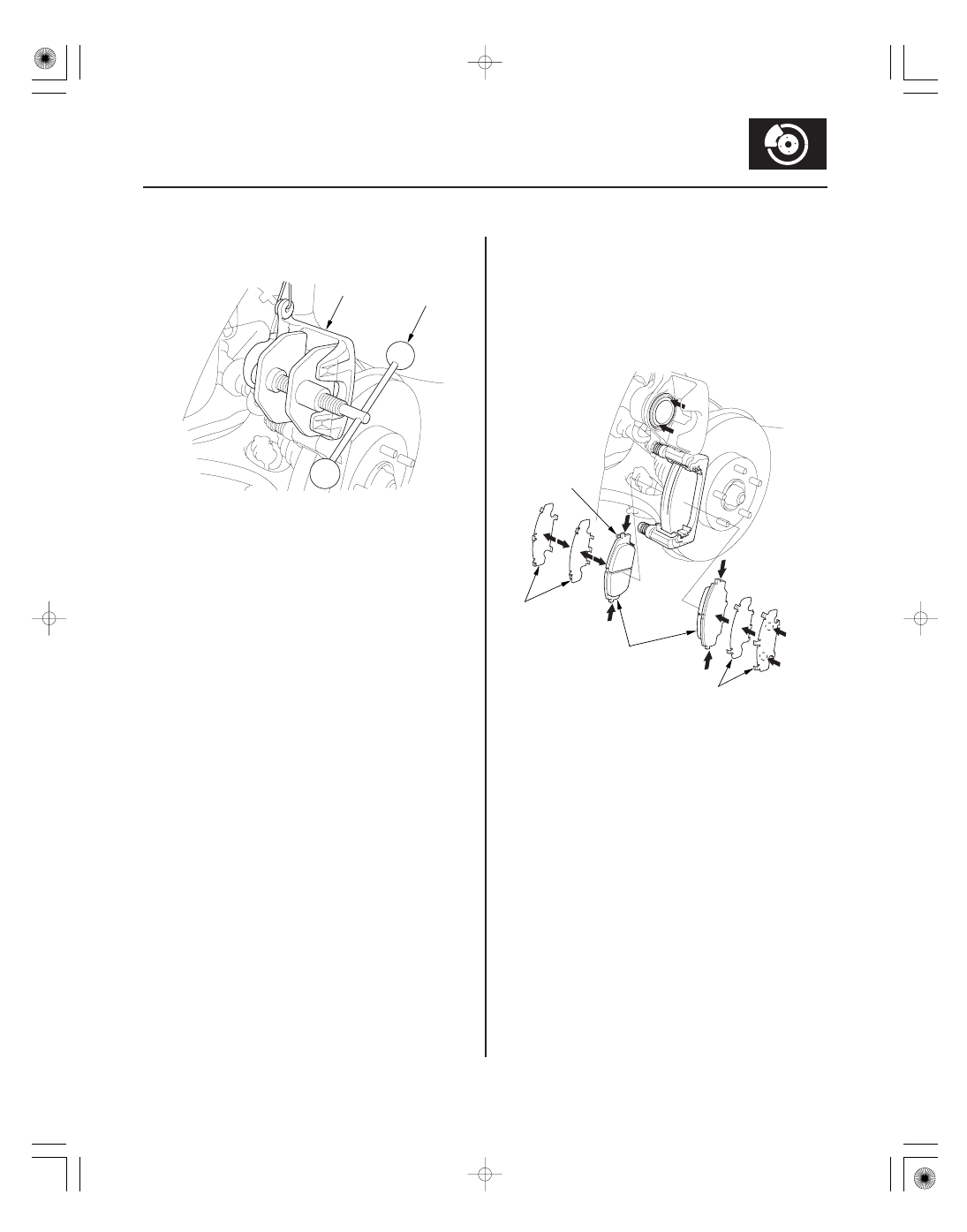
11. Install the brake caliper piston compressor tool (A)

on the caliper body (B).

12. Press in the piston with the brake caliper piston

compressor tool so the caliper will fit over the
brake pads. Make sure the piston boot is in position
to prevent damaging it when pivoting the caliper
down.

NOTE: Be careful when pressing in the piston;
brake fluid might overflow from the master
cylinder’s reservoir. If brake fluid gets on any
painted surface, wash it off immediately with water.

13. Remove the brake caliper piston compressor tool.

14. Apply a thin coat of M-77 assembly paste (P/N

08798-9010) to the pad side of the shims (A), the
back of the brake pads (B) and the other areas
indicated by the arrows. Wipe excess assembly
paste off the pad shims and the brake pads friction
material. Keep grease and assembly paste off the
brake disc and the brake pads. Contaminated brake
disc or brake pads reduce stopping ability.

15. Install the brake pads and the pad shims correctly.

Install the brake pad with the wear indicator (C) on
the upper inside. If you are reusing the brake pads,
always reinstall the brake pads in their original
positions to prevent a momentary loss of braking
efficiency.

08/08/21 15:00:56 61SNR030_190_0017

08

19-18

Conventional Brake Components

A
8 x 1.0 mm
33 N·m
(3.4 kgf·m,
25 lbf·ft)

B

16. Pivot the caliper down into position. Install the

flange bolt (A), and tighten it to the specified torque
while holding the caliper pin (B), with a wrench
being careful not to damage the pin boot.

17. Clean the mating surfaces between the brake disc

and the inside of the wheel, then install the front
wheels.

18. Press the brake pedal several times to make sure

the brakes work.

NOTE: Engagement may require a greater pedal
stroke immediately after the brake pads have been
replaced as a set. Several applications of the brake
pedal will restore the normal pedal stroke.

19. Add brake fluid as needed.

20. After installation, check for leaks at hose and line

joints or connections, and retighten if necessary.
Test-drive the vehicle, then recheck for leaks
(see page 19-37).

08/08/21 15:00:56 61SNR030_190_0018

01

SNR9A00D14300014721MAAT10

Runout

Brake disc runout:

Service limit: 0.04 mm (0.0016 in.)

Max. refinishing limit:

Except Type S model: 21.0 mm (0.83 in.)
Type S model:

23.0 mm (0.91 in.)

19-19

Front Brake Disc Inspection

B
108 N·m
(11.0 kgf·m, 79.6 lbf·ft)

A

10 mm
(0.39 in.)

1. Raise the front of the vehicle, and support it with

safety stands in the proper locations (see page
1-11).

2. Remove the front wheels.

3. Remove the brake pads: Except Type S model

(see page 19-13), Type S model (see page 19-16).

4. Inspect the brake disc to wheel surface for damage

and cracks. Clean the brake disc thoroughly, and
remove all rust.

5. Install suitable flat washers (A) and wheel nuts (B),

and tighten the wheel nuts to the specified torque
to hold the brake disc securely against the hub.

6. Set up the dial gauge against the brake disc as

shown, and measure the runout at 10 mm (0.39 in.)
from the outer edge of the brake disc.

7. If the brake disc is beyond the service limit, refinish

the brake disc with a Honda-approved
commercially available on-car brake lathe.

NOTE:

• If the brake disc is beyond the service limit for

refinishing, replace it (see page 19-21).

• If the brake disc is replaced with a new one,

check the new disc for runout. If the new disc is
out of specification, refinish the disc.

8. Install the brake pads: Except Type S model

(see page 19-13), Type S model (see page 19-16).

9. Clean the mating surfaces between the brake disc

and the inside of the wheel, then install the front
wheels.

08/08/21 15:00:57 61SNR030_190_0019

02

Thickness and Parallelism

Brake disc thickness:

Standard:

Except Type S model: 22.9

23.1 mm

(0.90

0.91 in.)

Type S model:

24.9

25.1 mm

(0.98

0.99 in.)

Max. refinishing limit:

Except Type S model: 21.0 mm (0.83 in.)
Type S model:

23.0 mm (0.91 in.)

Brake disc parallelism:

0.015 mm
(0.0006 in.) max.

19-20

Conventional Brake Components

10 mm
(0.39 in.)

1. Raise the front of the vehicle, and support it with

safety stands in the proper locations (see page
1-11).

2. Remove the front wheels.

3. Remove the brake pads: Except Type S model

(see page 19-13), Type S model (see page 19-16).

4. Using a micrometer, measure the brake disc

thickness at eight points, about 45 ° apart and
10 mm (0.39 in.) in from the outer edge of the brake
disc. Replace the brake disc if the smallest
measurement is less than the max. refinishing limit.

NOTE: This is the maximum allowable difference
between the thickness measurements.

5. If the brake disc is beyond the service limit for

parallelism, refinish the brake disc with a Honda-
approved commercially available on-car brake
lathe.

NOTE: If the brake disc is beyond the service limit
for refinishing, replace it (see page 19-21).

6. Install the brake pads: Except Type S model

(see page 19-13), Type S model (see page 19-16).

7. Clean the mating surfaces between the brake disc

and the inside of the wheel, then install the front
wheels.

08/08/21 15:00:57 61SNR030_190_0020


Content   ..  376  377  378  379   ..