Acura CSX. Manual - part 367
#
@
01
SNR9A0JB54175159634MAAT00
Special Tools Required
18-53
18-53
Tire Pressure Sensor Location
A
8. Turn the ignition switch to LOCK (0).
9. Disconnect the HDS from the DLC.
10. Test-drive the vehicle at 45 km/h (28 mph) or more
for at least 1 minute.
11. Make sure the low tire pressure indicator does not
blink.
12. Make sure the tires are inflated to the specified tire
pressure listed on the doorjamb sticker.
13. Turn the ignition switch to LOCK (0).
Bartech Wheelrite Tech300 TPMS tool J-48714
Available through Honda Canada Inc. Technical Tools
Department; Fax
866-398-8665/
e-mail: ch_technicaltools
ch.honda.com
NOTE:
• This procedure locates where the tire pressure
sensors 1, 2, 3, 4 are mounted, when activated by the
TPMS sensor initializer tool.
• Position the vehicle at least 3 m (10 ft) away from
other vehicles that have tire pressure sensors.
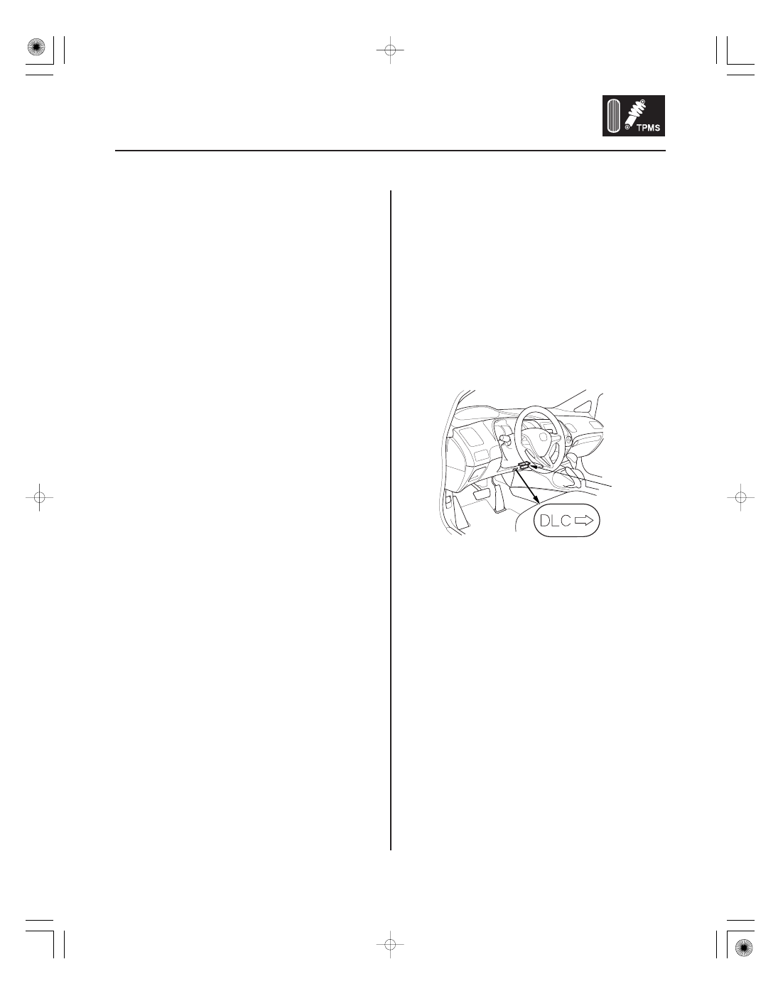
1. With the ignition switch in LOCK (0), connect the
HDS to the data link connector (DLC) (A) located
under the driver’s side of the dashboard.
2. Turn the ignition switch to ON (II).
3. Make sure the HDS communicates with the vehicle
and the TPMS control unit. If it doesn’t,
troubleshoot the DLC circuit (see page 11-204).
4. Select Function Test from the mode menu, then
select Sensor Position Check on the HDS.
08/08/21 14:58:23 61SNR030_180_0053