Acura CSX. Manual - part 315


  Index      Acura     Acura CSX - P/NO. 61SNR03 - service repair manual 2006-2009 year


Search            


Content   ..  313  314  315  316   ..


Acura CSX. Manual - part 315


05

06

07

08

14-333

E

D

C

B

A

E

D

C

B

A

A

C

B

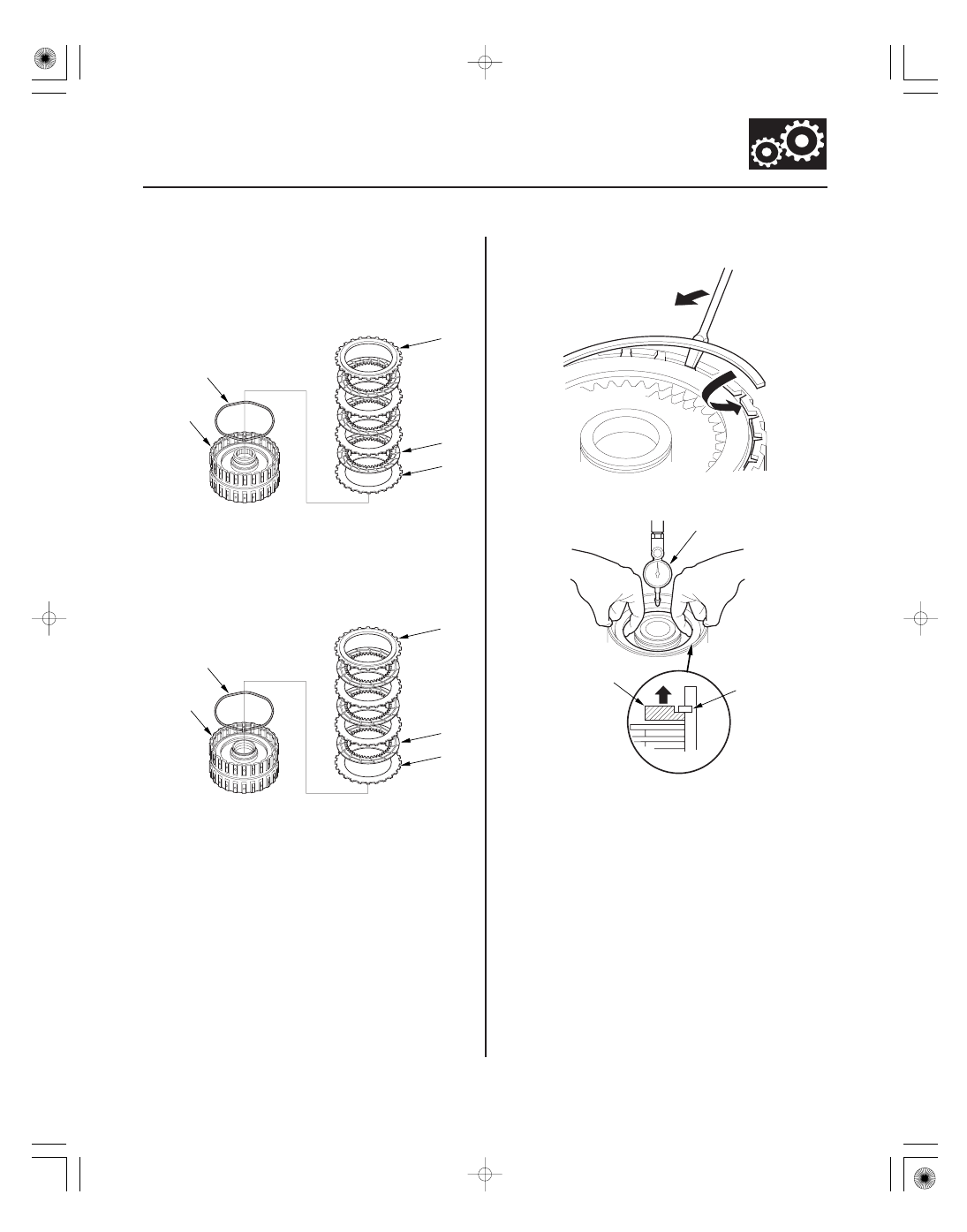
6. Install the waved spring (A) in the 4th clutch drum

(B). Starting with the clutch wave-plate, alternately
install the clutch wave-plates (C) (3), and the discs
(D) (3), and install the clutch end-plate (E) with the
flat side down on the top disc.

7. Install the waved spring (A) in the 5th clutch drum

(B). Starting with the clutch wave-plate, alternately
install the clutch wave-plates (C) (3), and the discs
(D) (3), and install the clutch end-plate (E) with the
flat side down on the top disc.

8. Install the snap ring using a screwdriver.

9. Set a dial indicator (A) on the clutch end-plate (B).

10. Zero the dial indicator with the clutch end-plate

lifted up to the snap ring (C).

08/08/21 14:52:21 61SNR030_140_0335

09

10

Clearance between Clutch End-Plate and Top Disc
Service Limit:
1st Clutch:

1.23

1.43 mm (0.048

0.056 in.)

2nd Clutch: 0.75

0.95 mm (0.030

0.037 in.)

3rd Clutch: 0.83

1.03 mm (0.033

0.041 in.)

4th Clutch: 0.73

0.93 mm (0.029

0.037 in.)

5th Clutch: 0.73

0.93 mm (0.029

0.037 in.)

1ST and 3RD CLUTCH END-PLATES

Mark

Part Number

Thickness

2ND CLUTCH END-PLATES

Mark

Part Number

Thickness

4TH and 5TH CLUTCH END-PLATES

Mark

Part Number

Thickness

14-334

Shafts and Clutches

B

A

D

C

07ZAE-PRP0100

11. Release the clutch end-plate to lower the clutch

end-plate, then put the clutch compressor
attachment on the end-plate (A).

12. Press the clutch compressor attachment down with

150

160 N (15

16 kgf, 33

35 lbf) using a force

gauge, and read the dial indicator (B).

13. The dial indicator reads the clearance (C) between

the clutch end-plate and top disc (D). Take
measurements in at least three places, and use
average as the actual clearance.

14. If the clearance is out of the service limit, select a

new clutch end-plate from the following table.

1

22551-PRP-003

2.3 mm (0.091 in.)

2

22552-PRP-003

2.4 mm (0.094 in.)

3

22553-PRP-003

2.5 mm (0.098 in.)

4

22554-PRP-003

2.6 mm (0.102 in.)

5

22555-PRP-003

2.7 mm (0.106 in.)

6

22556-PRP-003

2.8 mm (0.110 in.)

7

22557-PRP-003

2.9 mm (0.114 in.)

8

22558-PRP-003

3.0 mm (0.118 in.)

9

22559-PRP-003

3.1 mm (0.122 in.)

10

22560-PRP-003

3.2 mm (0.126 in.)

11

22561-PRP-003

3.3 mm (0.130 in.)

12

22562-PRP-003

3.4 mm (0.134 in.)

1

22571-PRP-003

2.6 mm (0.102 in.)

2

22572-PRP-003

2.7 mm (0.106 in.)

3

22573-PRP-003

2.8 mm (0.110 in.)

4

22574-PRP-003

2.9 mm (0.114 in.)

5

22575-PRP-003

3.0 mm (0.118 in.)

6

22576-PRP-003

3.1 mm (0.122 in.)

7

22577-PRP-003

3.2 mm (0.126 in.)

8

22578-PRP-003

3.3 mm (0.130 in.)

9

22579-PRP-003

3.4 mm (0.134 in.)

1

22581-R91-003 or
22581-R93-003

2.1 mm (0.083 in.)

2

22582-R91-003 or
22582-R93-003

2.2 mm (0.087 in.)

3

22583-R91-003 or
22583-R93-003

2.3 mm (0.091 in.)

4

22584-R91-003 or
22584-R93-003

2.4 mm (0.094 in.)

5

22585-R91-003 or
22585-R93-003

2.5 mm (0.098 in.)

6

22586-R91-003 or
22586-R93-003

2.6 mm (0.102 in.)

7

22587-R91-003 or
22587-R93-003

2.7 mm (0.106 in.)

8

22588-R91-003 or
22588-R93-003

2.8 mm (0.110 in.)

9

22589-R91-003 or
22589-R93-003

2.9 mm (0.114 in.)

15. Install a new clutch end-plate, then recheck the

clearance.

16. If the thickest clutch end-plate is installed, but the

clearance is still over the service limit, replace the
clutch discs and the plates.

08/08/21 14:52:22 61SNR030_140_0336

01

02

02

SNR9AA1E10411310041LDAT00

Special Tools Required

14-335

1st, 2nd, and 3rd Clutch Reassembly

A

D

B

C

A

B

A

B

C

Clutch spring compressor set 07LAE-PX40000

NOTE: Hold the spring compressor set in a vise with
soft jaws. Be careful not to damage the clutch drum.

1. Soak the clutch discs thoroughly in ATF for at least

30 minutes.

2. Install a new O-ring (A) in the 1st, 2nd, and 3rd

clutch pistons (B), and install a new O-ring (C) on
the clutch drums (D).

3. Install the clutch piston (A) in the clutch drum (B)

while applying pressure and rotating to ensure
proper seating. Do not pinch the O-ring.

4. Set the return spring (A) and the spring retainer (B)

on the clutch piston, and position the snap ring (C)
on the spring retainer.

08/08/21 14:52:23 61SNR030_140_0337

*01

04

05

06

14-336

Shafts and Clutches

07LAE-PX40000

A

B

C

A

B

5. Install the clutch spring compressor set.

6. Set the clutch spring compressor set (A) on the

spring retainer (B) so that it compresses the clutch
return spring (C).

NOTE: Coat the circumference of the spring
retainer and the areas where the spring retainer
contacts the clutch piston with ATF before
installation.

7. Compress the return spring carefully until the snap

ring can be installed. Check that the spring retainer
(A) is properly installed on the clutch hub (B). If
improperly installed, change the position of the
spring compressor set and the spring retainer.

NOTE: Insert the spring retainer so it can be
adjusted (center of tolerance) to prevent damaging
the spring retainer oil seal.

8. Install the snap ring using snap ring pliers.

9. Remove the clutch spring compressor set.

08/08/21 14:52:23 61SNR030_140_0338


Content   ..  313  314  315  316   ..