Acura CSX. Manual - part 284


  Index      Acura     Acura CSX - P/NO. 61SNR03 - service repair manual 2006-2009 year


Search            


Content   ..  282  283  284  285   ..


Acura CSX. Manual - part 284


*01

*02

*03

SNR9AA1E10410654801KBAT40

14-217

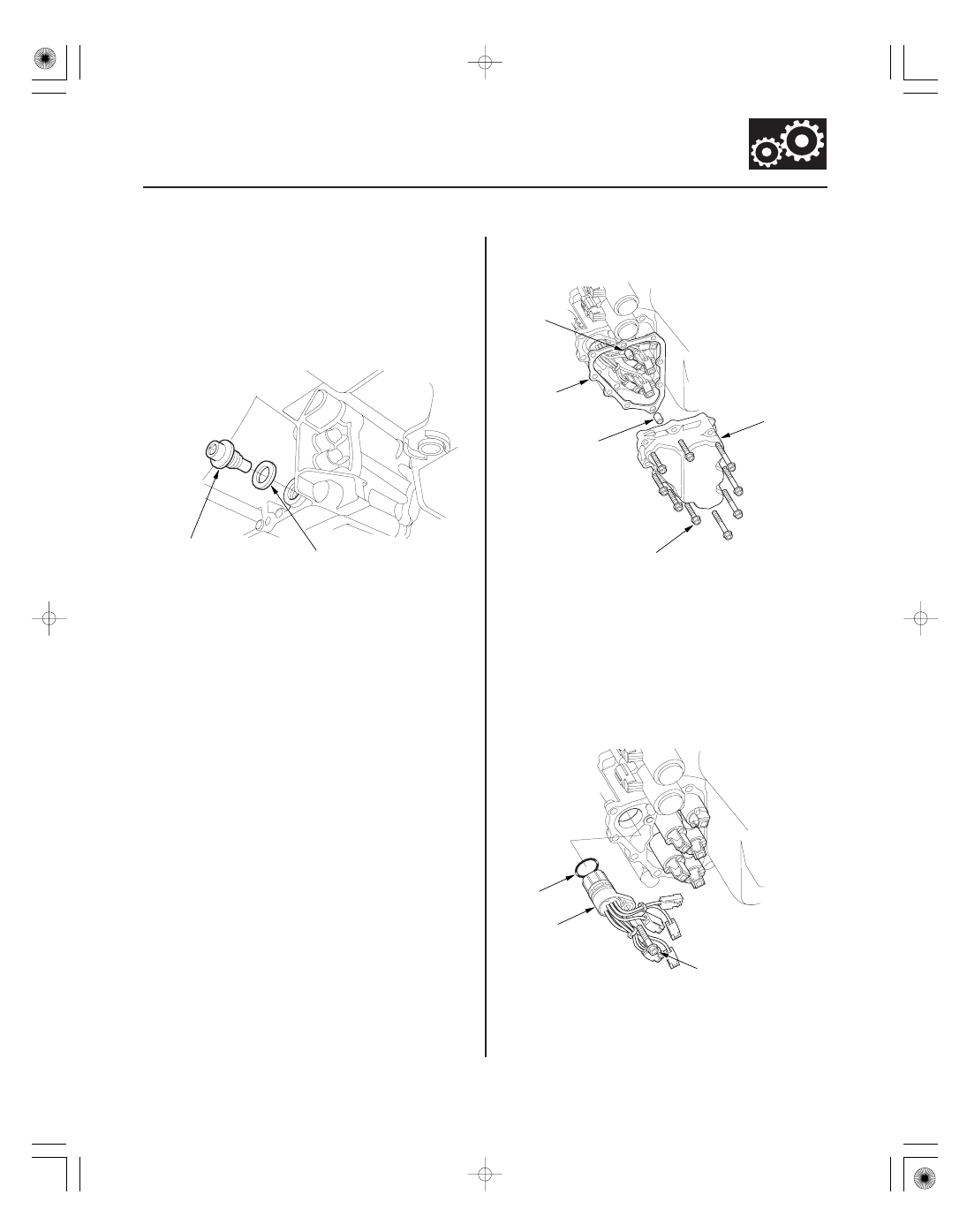
Shift Solenoid Valve and Shift Solenoid Wire Harness Replacement

A
18 x 1.5 mm
49 N·m
(5.0 kgf·m, 36 lbf·ft)

B

A

B

6 x 1.0 mm
12 N·m (1.2 kgf·m, 8.7 lbf·ft)

B

C

6 x 1.0 mm
12 N·m
(1.2 kgf·m, 8.7 lbf·ft)

A

B

1. Raise the vehicle on a lift, or apply the parking

brake, block the rear wheels, and raise the front of
the vehicle. Make sure it is securely supported.

2. Remove the splash shield.

3. Remove the drain plug (A), and drain the automatic

transmission fluid (ATF).

4. Reinstall the drain plug with a new sealing washer

(B).

5. Do the battery removal procedure (see page 22-69).

6. Remove the intake air duct (see page 11-348) and

the air cleaner assembly (see page 11-345).

7. Remove the battery tray, the battery base, and the

resonator.

8. Remove the shift solenoid valve cover (A), the

dowel pins (B), and the gasket (C).

9. Disconnect the shift solenoid valve connectors.

• If replacing the shift solenoid valve(s), go to step

10.

• If replacing the shift solenoid wire harness,

remove the shift solenoid wire harness connector
(A), and replace it. Install a new O-ring (B) on a
new shift solenoid wire harness connector, and
install it in the transmission housing, then go to
step 15.

Replace.

Replace.

Replace.

08/08/21 14:46:45 61SNR030_140_0219

04

14-218

Automatic Transmission

F
6 x 1.0 mm
12 N·m
(1.2 kgf·m,
8.7 lbf·ft)

A

D

E

F

B

F

C

G

H

G

G

G

G

10. Remove the mounting bolts (F), then hold the shift

solenoid valve body and remove the shift solenoid
valves. Do not hold the connector to remove the
shift solenoid valve.

11. Install new O-rings (two O-rings per solenoid valve)

(G) on the reused solenoid valve.

NOTE: A new solenoid valve comes with new
O-rings. If you install a new solenoid valve, use the
O-rings provided with it.

12. Install shift solenoid valves C (brown connector), D

(black connector), and E (black connector) by
holding the shift solenoid valve body; make sure
the mounting bracket contacts the servo body.

NOTE: Do not hold the shift solenoid valve
connector to install the shift solenoid valve. Be sure
to hold the shift solenoid valve body.

13. Install shift solenoid valve B (brown connector) by

holding the shift solenoid valve body; make sure
the mounting bracket contacts the bracket of shift
solenoid valve E.

14. Install shift solenoid valve A (brown connector) by

holding the shift solenoid valve body; make sure
the mounting bracket contacts the bracket of shift
solenoid valve D.

NOTE: Do not install shift solenoid valves A and B
before installing shift solenoid valve D and E. If
shift solenoid valve A or B is installed before
installing shift solenoid valve D or E, it may
damage to hydraulic control system.

15. Connect YEL, WHT, and WHT harnesses terminal

(H) to shift solenoid valve D. The ATF temperature
sensor is installed in the connector.

16. Connect the shift solenoid valve connectors:

• BLU wire to shift solenoid valve A
• ORN wire to shift solenoid valve B
• GRN wire to shift solenoid valve C
• RED wire to shift solenoid valve E

17. Install a new gasket, the dowel pins, and the shift

solenoid valve cover.

18. Check the connector for rust, dirt, or oil, then

connect the connector securely.

19. Refill the transmission with ATF (see step 5 on page

14-232).

20. Install the battery base, the battery tray, and the

resonator.

21. Install the air cleaner assembly (see page 11-345)

and the intake air duct (see page 11-348).

22. Do the battery installation procedure (see page

22-69).

23. Install the splash shield.

08/08/21 14:46:45 61SNR030_140_0220

01

01

SNR9AA1E10410612223FEAT20

Standard: 3

10

14-219

A/T Clutch Pressure Control Solenoid Valve A Test

A

A

1. Connect the HDS to the DLC (A) located under the

driver’s side of the dashboard.

2. Turn the ignition switch to ON (II). Make sure the

HDS communicates with the PCM. If it does not, go
to the DLC circuit troubleshooting (see page
11-204).

3. Select Clutch Pressure Control (Linear) Solenoid

Valve A in the Miscellaneous Test Menu with the
HDS.

4. Test A/T clutch pressure control solenoid valve A

with the HDS.

• If the valve tests OK, the test is complete.

Disconnect the HDS.

• If the valve does not test OK, follow the

instructions on the HDS.

• If the valve does not test OK, and the HDS does

not determine the cause, go to step 5.

5. Remove the intake air duct (see page 11-348) and

the air cleaner assembly (see page 11-345).

6. Disconnect the A/T clutch pressure control solenoid

valve A connector (A).

7. Measure the resistance between A/T clutch

pressure control solenoid valve A connector
terminals No. 1 and No. 2.

• If the resistance is within the standard, go to step

8.

• If the resistance is out of standard, replace A/T

clutch pressure control solenoid valve A
(see page 14-221).

8. Connect a jumper wire from the negative battery

terminal to solenoid valve A connector terminal
No. 2, and connect another jumper wire from the
positive battery terminal to connector terminal
No. 1.

• If a clicking sound is heard, the valve is OK, and

the test is complete, go to step 18.

• If no clicking sound is heard, go to step 9.

08/08/21 14:46:46 61SNR030_140_0221

*01

04

14-220

Automatic Transmission

A

C

B

6 x 1.0 mm
12 N·m
(1.2 kgf·m, 8.7 lbf·ft)

E

D

9. Remove the mounting bolts and A/T clutch

pressure control solenoid valve A.

10. Remove the ATF pipe (B), the ATF joint pipes (C),

the O-rings (D), and the gasket (E).

11. Check the fluid passage of the solenoid valve for

contamination.

12. Connect a jumper wire from the negative battery

terminal to A/T clutch pressure control solenoid
valve A connector terminal No. 2, and connect
another jumper wire from the positive battery
terminal to connector terminal No. 1. Make sure
A/T clutch pressure control solenoid valve A moves.

13. Disconnect one of the jumper wires, and check

valve movement at the fluid passage in the valve
body mounting surface. If the valve binds or moves
sluggishly, or if the solenoid valve does not operate,
replace A/T clutch pressure control solenoid
valve A.

14. Clean the mounting surfaces and the fluid passages

of the A/T clutch pressure control solenoid valve
body and the transmission housing.

15. Install a new gasket on the transmission housing,

and install the ATF pipe and the ATF joint pipes.

NOTE: Be sure to install a new gasket with the blue
side toward the transmission housing.

16. Install new O-rings over the ATF joint pipes.

17. Install A/T clutch pressure control solenoid valve A.

18. Check the connectors for rust, dirt, or oil, clean or

repair if necessary, then connect the connectors
securely.

19. Install the air cleaner assembly (see page 11-345)

and the intake air duct (see page 11-348).

Replace.

Replace.

08/08/21 14:46:46 61SNR030_140_0222


Content   ..  282  283  284  285   ..