Acura CSX. Manual - part 151


  Index      Acura     Acura CSX - P/NO. 61SNR03 - service repair manual 2006-2009 year


Search            


Content   ..  149  150  151  152   ..


Acura CSX. Manual - part 151


01

YES

NO

YES

NO

YES

NO

YES

NO

YES

NO

11-277

A

8. Monitor the OBD STATUS for DTC P0011 in the

DTCs MENU with the HDS.

Go to step 9.

If the screen indicates PASSED, intermittent

failure, the system is OK at this time. If the screen
indicates NOT COMPLETED, go to step 5 and
recheck.

9. Turn the ignition switch to LOCK (0).

10. Remove the auto-tensioner (see page 4-32).

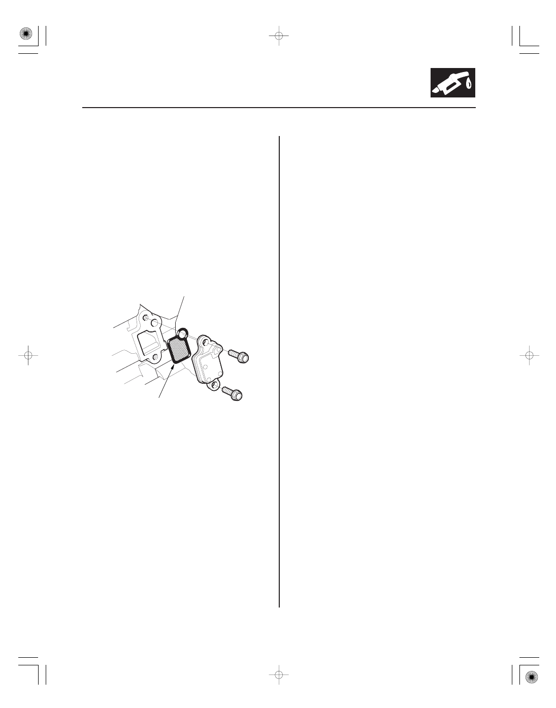
11. Remove the VTC strainer (A), and check it for

clogging.

Go to step 12.

Clean the VTC strainer, replace the engine oil

filter and the engine oil, then go to step 14.

12. Test the VTC oil control solenoid valve (see page

11-294).

Go to step 13.

Replace the VTC oil control solenoid valve

(see page 11-294), then go to step 14.

13. Inspect the VTC actuator (see page 6-11).

Go to step 14.

Replace the VTC actuator (see page 6-42),

then go to step 14.

14. Turn the ignition switch to ON (II).

15. Reset the ECM/PCM with the HDS.

16. Clear the CKP pattern with the HDS.

17. Do the ECM/PCM idle learn procedure (see page

11-310).

18. Do the CKP pattern learn procedure (see page 11-4).

19. Do the VTC TEST in the INSPECTION MENU with

the HDS.

20. Check for Temporary DTCs or DTCs with the HDS.

Check for poor connections or loose

terminals at the VTC oil control solenoid valve and
the ECM/PCM, then go to step 1.

Go to step 21.

Does the scr een indicate F AILED?

Is the str ainer OK ?

Is the V T C oil contr ol solenoid valve OK ?

Is the V T C actuator OK ?

Is DT C P0011 indicated?

08/08/21 14:28:22 61SNR030_110_0277

01

SNR9AA7K72100090340FAAT10

YES

NO

YES

NO

YES

NO

DTC P0340:

11-278

11-278

VTEC/VTC

CMP SENSOR A 3P CONNECTOR

IG1 (BLK/YEL)

21. Monitor the OBD STATUS for DTC P0011 in the

DTCs MENU with the HDS.

Troubleshooting is complete. If any other

Temporary DTCs or DTCs were indicated in step 20,
go to the indicated DTC’s troubleshooting.

If the screen indicates FAILED, check for poor

connections or loose terminals at the VTC oil
control solenoid valve and the ECM/PCM, then go
to step 1. If the screen indicates NOT COMPLETED,
go to step 19 and recheck.

NOTE: Before you troubleshoot, record all freeze data
and any on-board snapshot, and review the general
troubleshooting information (see page 11-3).

1. Turn the ignition switch to ON (II).

2. Clear the DTC with the HDS.

3. Start the engine.

4. Check for Temporary DTCs or DTCs with the HDS.

Go to step 5.

Intermittent failure, the system is OK at this

time. Check for poor connections or loose terminals
at CMP sensor A and the ECM/PCM.

5. Turn the ignition switch to LOCK (0).

6. Disconnect CMP sensor A 3P connector.

7. Turn the ignition switch to ON (II).

8. Measure the voltage between CMP sensor A 3P

connector terminal No. 3 and body ground.

Go to step 9.

Repair open in the wire between CMP sensor

A and the No. 3 ALTERNATOR (10 A) fuse then go
to step 18.

CMP Sensor A No Signal

Wire side of female terminals

Does the scr een indicate PASSED?

Is DT C P0340 indicated?

Is ther e batter y voltage?

08/08/21 14:28:22 61SNR030_110_0278

02

03

04

YES

NO

YES

NO

YES

NO

11-279

CMPA (BLU/WHT)

CMP SENSOR A 3P CONNECTOR

IG1
(BLK/YEL)

LG
(BRN/YEL)

CMP SENSOR A 3P CONNECTOR

ECM/PCM CONNECTOR C (44P)

CMPA (BLU/WHT)

9. Measure the voltage between CMP sensor A 3P

connector terminal No. 1 and body ground.

Go to step 10.

Go to step 11.

10. Measure the voltage between CMP sensor A 3P

connector terminals No. 2 and No. 3.

Go to step 16.

Repair open in the wire between CMP sensor

A and G101; A/T model (see page 22-16), M/T
model (see page 22-18), then go to step 18.

11. Turn the ignition switch to LOCK (0).

12. Jump the SCS line with the HDS.

13. Disconnect ECM/PCM connector C (44P).

14. Check for continuity between ECM/PCM connector

terminal C41 and body ground.

Repair short in the wire between the ECM/

PCM (C41) and CMP sensor A, then go to step 18.

Go to step 15.

Wire side of female terminals

Wire side of female terminals

Terminal side of female terminals

Is ther e about 5 V ?

Is ther e batter y voltage?

Is ther e continuity?

08/08/21 14:28:23 61SNR030_110_0279

05

YES

NO

YES

NO

YES

NO

11-280

VTEC/VTC

ECM/PCM CONNECTOR C (44P)

CMPA (BLU/WHT)

CMP SENSOR A 3P CONNECTOR

CMPA (BLU/WHT)

15. Check for continuity between CMP sensor A 3P

connector terminal No. 1 and ECM/PCM connector
terminal C41.

Go to step 23.

Repair open in the wire between the ECM/

PCM (C41) and CMP sensor A, then go to step 18.

16. Turn the ignition switch to LOCK (0).

17. Replace CMP sensor A (see page 11-295).

18. Reconnect all connectors.

19. Turn the ignition switch to ON (II).

20. Reset the ECM/PCM with the HDS.

21. Do the ECM/PCM idle learn procedure (see page

11-310).

22. Check for Temporary DTCs or DTCs with the HDS.

Check for poor connections or loose

terminals at CMP sensor A and the ECM/PCM, then
go to step 1.

Troubleshooting is complete. If any other

Temporary DTCs or DTCs are indicated, go to the
indicated DTC’s troubleshooting.

23. Reconnect all connectors.

24. Update the ECM/PCM if it does not have the latest

software (see page 11-227), or substitute a known-
good ECM/PCM (see page 11-7).

25. Check for Temporary DTCs or DTCs with the HDS.

Check for poor connections or loose

terminals at CMP sensor A and the ECM/PCM. If the
ECM/PCM was updated, substitute a known-good
ECM/PCM (see page 11-7), then recheck. If the
ECM/PCM was substituted, go to step 1.

If the ECM/PCM was updated, troubleshooting

is complete. If the ECM/PCM was substituted,
replace the original ECM/PCM (see page 11-228). If
any other Temporary DTCs or DTCs are indicated,
go to the indicated DTC’s troubleshooting.

Wire side of female terminals

Terminal side of female terminals

Is ther e continuity?

Is DT C P0340 indicated?

Is DT C P0340 indicated?

08/08/21 14:28:23 61SNR030_110_0280


Content   ..  149  150  151  152   ..