Acura CSX. Manual - part 107


  Index      Acura     Acura CSX - P/NO. 61SNR03 - service repair manual 2006-2009 year


Search            


Content   ..  105  106  107  108   ..


Acura CSX. Manual - part 107


07

03

04

YES

NO

YES

NO

11-102

PGM-FI System

A/F SENSOR (SENSOR 1) 4P CONNECTOR

B (PUR)

JUMPER WIRE

PGM-FI SUBRELAY 4P CONNECTOR

B

SUBRLY (PNK)

ECM/PCM CONNECTOR A (44P)

SUBRLY

PGM-FI SUBRELAY 4P CONNECTOR

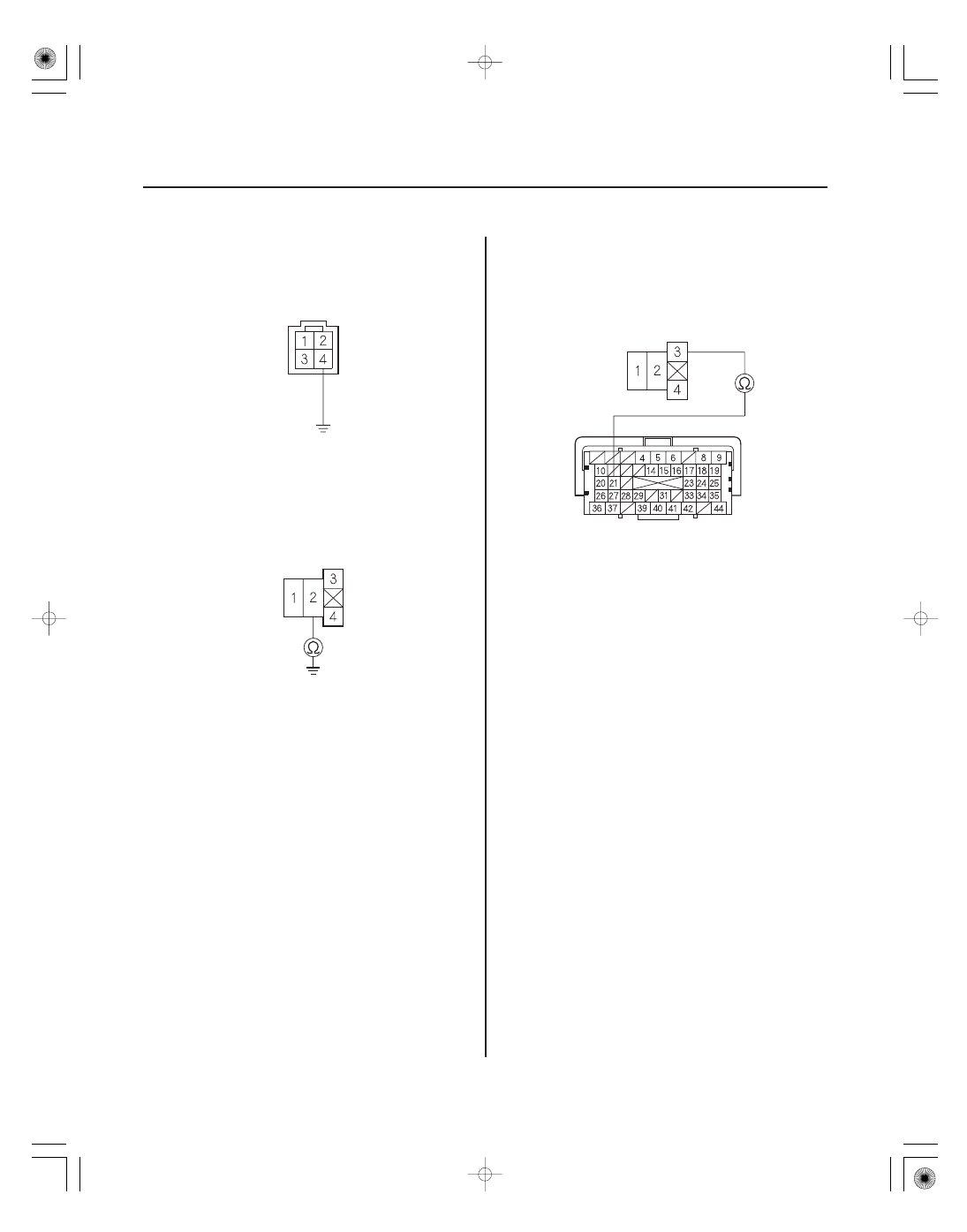
16. Connect A/F sensor (Sensor 1) 4P connector

terminal No. 4 to body ground with a jumper wire.

17. Check for continuity between PGM-FI subrelay 4P

connector terminal No. 2 and body ground.

Go to step 18.

Repair open in the wire between the A/F

sensor (Sensor 1) and the PGM-FI subrelay, then go
to step 25.

18. Disconnect ECM/PCM connector A (44P).

19. Check for continuity between PGM-FI subrelay 4P

connector terminal No. 3 and ECM/PCM connector
terminal A21.

Go to step 31.

Repair open in the wire between the ECM/

PCM (A21) and the PGM-FI subrelay, then go to
step 25.

Terminal side of male terminals

Terminal side of female terminals

Terminal side of female terminals

Terminal side of female terminals

Is ther e continuity?

Is ther e continuity?

08/08/21 14:17:20 61SNR030_110_0102

*03

06

YES

NO

YES

NO

YES

NO

11-103

E

A/F SENSOR (SENSOR 1) 4P CONNECTOR

B (PUR)

20. Remove the PGM-FI subrelay (E) from the under-

hood fuse/relay box.

21. Disconnect the A/F sensor (Sensor 1) 4P connector.

22. Disconnect the EVAP canister vent shut valve 2P

connector.

23. Check for continuity between A/F sensor (Sensor 1)

4P connector terminal No. 4 and body ground.

Repair short in the wire between the PGM-FI

subrelay, the EVAP canister vent shut valve, and
the A/F sensor (Sensor 1). Also replace the No. 11
FI SUB (15 A) fuse, then go to step 25.

Replace the under-hood fuse/relay box

(see page 22-65), then go to step 25.

24. Replace the A/F sensor (Sensor 1) (see page

11-221).

25. Reconnect all connectors.

26. Turn the ignition switch to ON (II).

27. Reset the ECM/PCM with the HDS.

28. Do the ECM/PCM idle learn procedure (see page

11-310).

29. Check for Temporary DTCs or DTCs with the HDS.

Check for poor connections or loose

terminals at the A/F sensor (Sensor 1), the PGM-FI
subrelay, and the ECM/PCM, then go to step 1.

Go to step 30.

30. Monitor the OBD STATUS for DTC P0135 in the

DTCs MENU with the HDS.

Troubleshooting is complete. If any other

Temporary DTCs or DTCs were indicated in step 29,
go to the indicated DTC’s troubleshooting.

If the screen indicates FAILED, check for poor

connections or loose terminals at the A/F sensor
(Sensor 1), the PGM-FI subrelay, and the ECM/PCM,
then go to step 1. If the screen indicates NOT
COMPLETED, keep idling until a result comes on.

Terminal side of male terminals

Is ther e continuity?

Is DT C P0135 indicated?

Does the scr een indicate PASSED?

08/08/21 14:17:21 61SNR030_110_0103

SNR9AA7K72100090137FAAT02

YES

NO

YES

NO

YES

NO

YES

NO

DTC P0137:

11-104

11-104

PGM-FI System

31. Reconnect all connectors.

32. Update the ECM/PCM if it does not have the latest

software (see page 11-227), or substitute a known-
good ECM/PCM (see page 11-7).

33. Start the engine, and let it idle.

34. Check for Temporary DTCs or DTCs with the HDS.

Check for poor connections or loose

terminals at the A/F sensor (Sensor 1), the PGM-FI
subrelay, and the ECM/PCM. If the ECM/PCM was
updated, substitute a known-good ECM/PCM
(see page 11-7), then go to step 33. If the ECM/PCM
was substituted, go to step 1.

Go to step 35.

35. Monitor the OBD STATUS for DTC P0135 in the

DTCs MENU with the HDS.

If the ECM/PCM was updated,

troubleshooting is complete. If the ECM/PCM was
substituted, replace the original ECM/PCM
(see page 11-228). If any other Temporary DTCs or
DTCs were indicated in step 34, go to the indicated
DTC’s troubleshooting.

If the screen indicates FAILED, check for poor

connections or loose terminals at the A/F sensor
(Sensor 1), the PGM-FI subrelay, and the ECM/PCM.
If the ECM/PCM was updated, substitute a known-
good ECM/PCM (see page 11-7), then go to step 33.
If the ECM/PCM was substituted, go to step 1. If the
screen indicates NOT COMPLETED, keep idling
until a result comes on.

NOTE:

• Before you troubleshoot, record all freeze data and

any on-board snapshot, and review the general
troubleshooting information (see page 11-3).

• Information marked with an asterisk( ) applies

to ’07-09 models.

1. Turn the ignition switch to ON (II).

2. Clear the DTC with the HDS.

3. Start the engine. Hold the engine speed at

3,000 rpm (A/T in P or N, M/T in neutral) until the
radiator fan comes on, then let it idle.

4. Check the HO2S S2 in the DATA LIST with the HDS.

Go to step 5.

Intermittent failure, the system is OK at this

time. Check for poor connections or loose terminals
at the secondary HO2S (Sensor 2) and the ECM/
PCM.

5. Turn the ignition switch to LOCK (0).

6. Remove the center console (see page 20-92).

7. Disconnect the secondary HO2S (Sensor 2) 4P

connector.

8. Turn the ignition switch to ON (II).

9. Check the HO2S S2 in the DATA LIST with the HDS.

Go to step 10.

Go to step 14.

10. Turn the ignition switch to LOCK (0).

11. Jump the SCS line with the HDS.

12. Disconnect ECM/PCM connector C (44P).

Secondary HO2S (Sensor 2)

Circuit Low Voltage

Is DT C P0135 indicated?

Does the scr een indicate PASSED?

Does the voltage stay at 0.29 ( 0.05) V or less?

Does the voltage stay at 0.29 ( 0.05) V or less?

08/08/21 14:17:21 61SNR030_110_0104

01

YES

NO

YES

NO

YES

NO

11-105

SECONDARY HO2S (SENSOR 2) 4P CONNECTOR

SHO2S (WHT)

13. Check for continuity between secondary HO2S

(Sensor 2) 4P connector terminal No. 2 and body
ground.

Repair short in the wire between the ECM/

PCM (C27) and the secondary HO2S (Sensor 2),
then go to step 16.

Go to step 24.

14. Turn the ignition switch to LOCK (0).

15. Replace the secondary HO2S (Sensor 2) (see page

11-221).

16. Reconnect all connectors.

17. Turn the ignition switch to ON (II).

18. Reset the ECM/PCM with the HDS.

19. Do the ECM/PCM idle learn procedure (see page

11-310).

20. Start the engine, and let it idle without load (A/T in

P or N, M/T in neutral) until the radiator fan comes
on.

21. Test-drive under these conditions:

• Engine coolant temperature (ECT SENSOR 1)

above 70 °C (158 °F)

• A/T in D, M/T in 4th
• Engine speed between 1,500

3,000 rpm

• Drive about 1 minute or more

22. Check for Temporary DTCs or DTCs with the HDS.

Check for poor connections or loose

terminals at the secondary HO2S (Sensor 2) and
the ECM/PCM, then go to step 1.

Go to step 23.

23. Monitor the OBD STATUS for DTC P0137 in the

DTCs MENU with the HDS.

Troubleshooting is complete. If any other

Temporary DTCs or DTCs were indicated in step 22,
go to the indicated DTC’s troubleshooting.

If the screen indicates FAILED, check for poor

connections or loose terminals at the secondary
HO2S (Sensor 2) and the ECM/PCM, then go to step
1. If the screen indicates EXECUTING, keep driving
until a result comes on. If the screen indicates OUT
OF CONDITION, go to step 20.

Terminal side of male terminals

Is ther e continuity?

Is DT C P0137 indicated?

Does the scr een indicate PASSED?

08/08/21 14:17:21 61SNR030_110_0105


Content   ..  105  106  107  108   ..