Acura CSX. Manual - part 89


  Index      Acura     Acura CSX - P/NO. 61SNR03 - service repair manual 2006-2009 year


Search            


Content   ..  87  88  89  90   ..


Acura CSX. Manual - part 89


*08

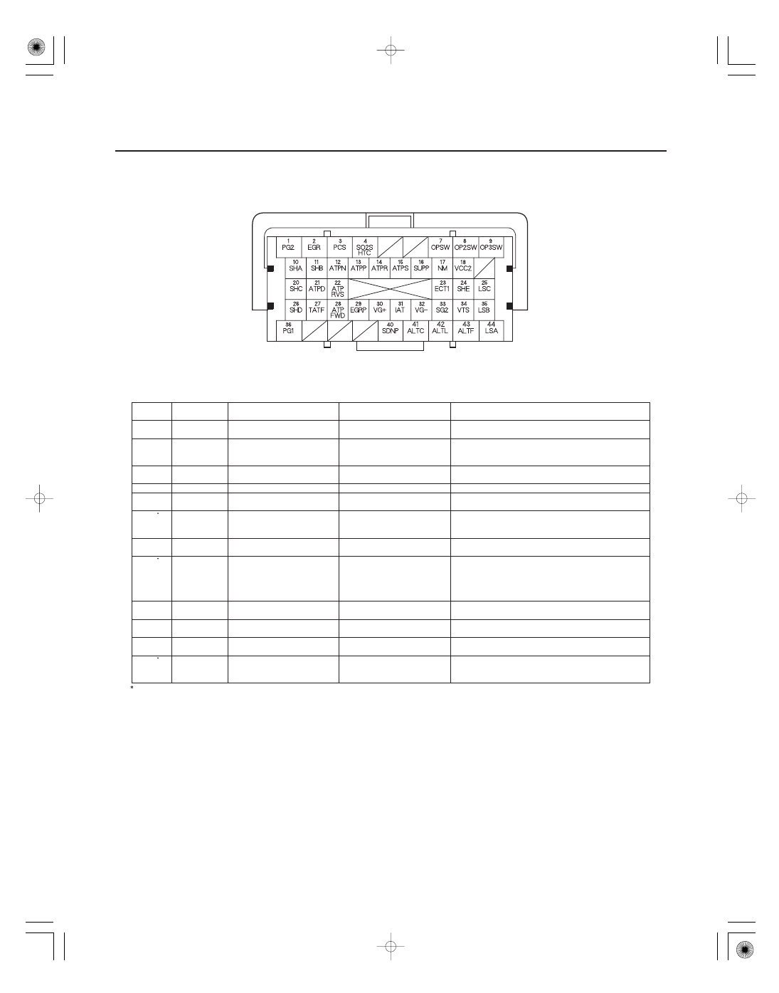
ECM/PCM Inputs and Outputs at Connector B (

) (44P)

Terminal

number

Wire color

Terminal name

Description

Signal

11-30

Fuel and Emissions Systems

NOTE: Standard battery voltage is about 12 V.

30

RED/BLK

VG

(MASS AIR FLOW

(MAF) SENSOR

SIDE)

Detects MAF sensor signal

At idle: about 1.1

1.6 V

(between VG

terminal and VG

terminal)

31

RED/YEL

IAT (INTAKE AIR
TEMPERATURE (IAT)
SENSOR)

Detects IAT sensor signal

With ignition switch ON (II): about 0.1

4.0 V

(about 1.8 V at normal operating temperature)

32

BLK/BLU

VG

(MASS AIR FLOW

(MAF) SENSOR

SIDE)

Ground for MAF sensor
signal

33

GRN/BLK

SG2 (SENSOR GROUND)

Sensor ground

Less than 1.0 V at all times

34

GRN/YEL

VTS (ROCKER ARM OIL
CONTROL SOLENOID)

Drives rocker arm oil
control solenoid

At idle: about 0 V

35

BRN

LSB (A/T CLUTCH
PRESSURE CONTROL
SOLENOID VALVE B)

Drives A/T clutch pressure
control solenoid valve B

With ignition switch ON (II): current controlled

36

BLK

PG1 (POWER GROUND)

Ground circuit for ECM/
PCM

Less than 1.0 V at all times

40

BRN

SDNP (PADDLE SHIFTER
(DOWN SHIFT SWITCH))

Detects paddle shifter
(downshift switch) signal

In S:

With paddle shifter

(downshift switch) pressed:

about 0 V
With paddle shifter

(downshift switch) released:

about 5.0 V

41

WHT/GRN

ALTC (ALTERNATOR
CONTROL)

Sends alternator control
signal

With warmed up engine running: about 5.0 V
(depending on electrical load)

42

WHT/BLU

ALTL (ALTERNATOR L
SIGNAL)

Detects alternator L signal

With ignition switch ON (II): about 0 V
With engine running: battery voltage

43

WHT/RED

ALTF (ALTERNATOR FR
SIGNAL)

Detects alternator FR signal

With engine running: about 2.6

3.4 V

(depending on electrical load)

44

RED/BLK

LSA (A/T CLUTCH
PRESSURE CONTROL
SOLENOID VALVE A)

Drives A/T clutch pressure
control solenoid valve A

With ignition switch ON (II): current controlled

1: A/T

1

1

1

Terminal side of female terminals

08/08/21 14:12:44 61SNR030_110_0030

08

ECM/PCM Inputs and Outputs at Connector C (

) (44P)

Terminal

number

Wire color

Terminal name

Description

Signal

11-31

NOTE: Standard battery voltage is about 12 V.

1

WHT

IG1ETCS (IGNITION
SIGNAL ETCS)

Detects ignition signal

With ignition switch ON (II): battery voltage

2

BLK

PGMETCS (POWER
GROUND ETCS)

Ground circuit for ECM/
PCM

Less than 1.0 V at all times

3

GRN/YEL

ETCSM

(THROTTLE

ACTUATOR

SIDE)

Ground for throttle actuator

With ignition switch ON (II): about 0 V

4

BLU/RED

ETCSM

(THROTTLE

ACTUATOR

SIDE)

Drives throttle actuator

With ignition switch ON (II): about 0 V

5

BRN

INJ1 (No. 1 INJECTOR)

Drives No. 1 injector

At idle: duty controlled
With ignition switch ON (II): battery voltage

6

RED

INJ2 (No. 2 INJECTOR)

Drives No. 2 injector

7

BLU

INJ3 (No. 3 INJECTOR)

Drives No. 3 injector

8

YEL

INJ4 (No. 4 INJECTOR)

Drives No. 4 injector

9

WHT/GRN

AFSHTC (AIR FUEL RATIO
(A/F) SENSOR HEATER
CONTROL (SENSOR 1))

Drives A/F sensor heater
(sensor 1)

With ignition switch ON (II): battery voltage
With fully warmed up engine running: about 0 V

11

GRN/RED

MAP (MANIFOLD
ABSOLUTE PRESSURE
(MAP) SENSOR)

Detects MAP sensor signal

With ignition switch ON (II): about 3.0 V
At idle: about 1.0 V (depending on engine speed)

12

BLU

VCC3 (SENSOR VOLTAGE)

Provides sensor reference
voltage

With ignition switch ON (II): about 5.0 V

13

YEL/RED

VCC1 (SENSOR VOLTAGE)

Provides sensor reference
voltage

With ignition switch ON (II): about 5.0 V

14

GRN/WHT

SG1 (SENSOR GROUND)

Sensor ground

Less than 1.0 V at all times

15

YEL/GRN

IGPLS1 (No. 1 IGNITION
COIL PULSE)

Drives No. 1 ignition coil

With ignition switch ON (II): about 0 V
With engine running: pulses

16

BLU/RED

IGPLS2 (No. 2 IGNITION
COIL PULSE)

Drives No. 2 ignition coil

17

WHT/BLU

IGPLS3 (No. 3 IGNITION
COIL PULSE)

Drives No. 3 ignition coil

18

BRN

IGPLS4 (No. 4 IGNITION
COIL PULSE)

Drives No. 4 ignition coil

20

RED/BLK

TPSA (THROTTLE
POSITION (TP) SENSOR A)

Detects TP sensor A signal

With throttle fully open: about 3.9 V
With throttle fully closed: about 0.9 V

21

RED/BLU

TPSB (THROTTLE
POSITION (TP) SENSOR B)

Detects TP sensor B signal

With throttle fully open: about 4.1 V
With throttle fully closed: about 1.7 V

Terminal side of female terminals

08/08/21 14:13:36 61SNR030_110_0031

09

ECM/PCM Inputs and Outputs at Connector C (

) (44P)

Terminal

number

Wire color

Terminal name

Description

Signal

11-32

Fuel and Emissions Systems

NOTE: Standard battery voltage is about 12 V.

22

BLU/BLK

VTPSW (ROCKER ARM OIL
PRESSURE SWITCH)

Detects rocker arm oil
pressure switch signal

With engine at low speed: about 0 V
With engine at high speed: battery voltage

23

BLU/WHT

VTC (VTC OIL CONTROL
SOLENOID VALVE)

Drives VTC oil control
solenoid valve

with ignition switch ON (II): about 0 V

27

WHT/RED

SHO2S (SECONDARY
HEATED OXYGEN SENSOR
(SECONDARY HO2S)
(SENSOR 2))

Detects secondary HO2S
(sensor 2) signal

With throttle fully opened from idle and warmed up
engine: about 0.6 V
With throttle quickly closed: below 0.4 V

29

RED

AFS

(AIR FUEL RATIO

(A/F) SENSOR (SENSOR 1)

SIDE)

Detects A/F sensor
(sensor 1) signal

30

RED/YEL

AFS

(AIR FUEL RATIO

(A/F) SENSOR (SENSOR 1)

SIDE)

Detects A/F sensor
(sensor 1) signal

31

GRN

CMPB (CAMSHAFT
POSITION (CMP) SENSOR
B)

Detects CMP sensor B
signal

With engine running: pulses

32

BLU/YEL

CKP (CRANKSHAFT
POSITION (CKP) SENSOR)

Detects CKP sensor signal

With engine running: pulses

36

BLK/GRN

IG1 (IGNITION SIGNAL)

Detects ignition signal

With ignition switch ON (II): battery voltage

39

GRN

SG3 (SENSOR GROUND)

Sensor ground

Less than 1.0 V at all times

40

BRN/YEL

LG1 (LOGIC GROUND)

Ground circuit for ECM/
PCM

Less than 1.0 V at all times

41

BLU/WHT

CMPA (CAMSHAFT
POSITION (CMP) SENSOR
A)

Detects CMP sensor A
signal

With engine running: pulses

42

RED/BLU

KS (KNOCK SENSOR)

Detects knock sensor signal

With engine knocking: pulses

43

BLK/WHT

NC (OUTPUT SHAFT
(COUNTERSHAFT) SPEED
SENSOR)

Detects output shaft
(countershaft) speed sensor
signals

With ignition switch ON (II): pulses
With vehicle moving: about 5.0 V (pulses)

44

BRN/YEL

LG2 (LOGIC GROUND)

Ground circuit for ECM/
PCM

Less than 1.0 V at all times

Terminal side of female terminals

08/08/21 14:13:36 61SNR030_110_0032

16

17

18

19

PGM-FI System

Air Conditioning (A/C) Compressor Clutch Relay

Air Fuel Ratio (A/F) Sensor

Barometric Pressure (BARO) Sensor

Camshaft Position (CMP) Sensor B

Crankshaft Position (CKP) Sensor

Engine Coolant Temperature (ECT) Sensor 1 and 2

Ignition Timing Control

Injector Timing and Duration

11-33

ZIRCONIA
ELEMENT

SENSOR
TERMINALS

HEATER
TERMINALS

O-RING

MAGNET

TERMINAL

TERMINAL

O-RING

MAGNET

THERMISTOR

O-RING

TERMINAL

The programmed fuel injection (PGM-FI) system is a
sequential multiport fuel injection system.

When the ECM/PCM receives a demand for cooling
from the A/C system, it delays the compressor from
being energized, and enriches the mixture to assure
smooth transition to the A/C mode.

The A/F sensor operates over a wide air/fuel range. The
A/F sensor is installed upstream of the TWC, and sends
signals to the ECM/PCM which varies the duration of
fuel injection accordingly.

The BARO sensor is inside the ECM/PCM. It converts
atmospheric pressure into a voltage signal that
modifies the basic duration of the fuel injection
discharge.

CMP sensor B detects the position of the No. 1 cylinder
as a reference for sequential fuel injection to each
cylinder.

The CKP sensor detects crankshaft speed and is used by
the ECM/PCM to determine the ignition timing, timing
for the fuel injection of each cylinder, and engine
misfire detection.

ECT sensors 1 and 2 are temperature dependent
resistors (thermistors). The resistance decreases as the
engine coolant temperature increases.

The ECM/PCM contains the memory for basic ignition
timing at various engine speeds and manifold absolute
pressures. It also adjusts the timing according to engine
coolant temperature and intake air temperature.

The ECM/PCM contains the memory for basic discharge
duration at various engine speeds and manifold
pressures. The basic discharge duration, after being
read out from the memory, is further modified by
signals sent from various sensors to obtain the final
discharge duration.
By monitoring long term fuel trim, the ECM/PCM
detects long term malfunctions in the fuel system and
sets diagnostic trouble codes (DTCs) if needed.

08/08/21 14:13:37 61SNR030_110_0033


Content   ..  87  88  89  90   ..