Acura CSX. Manual - part 88
−
06
□
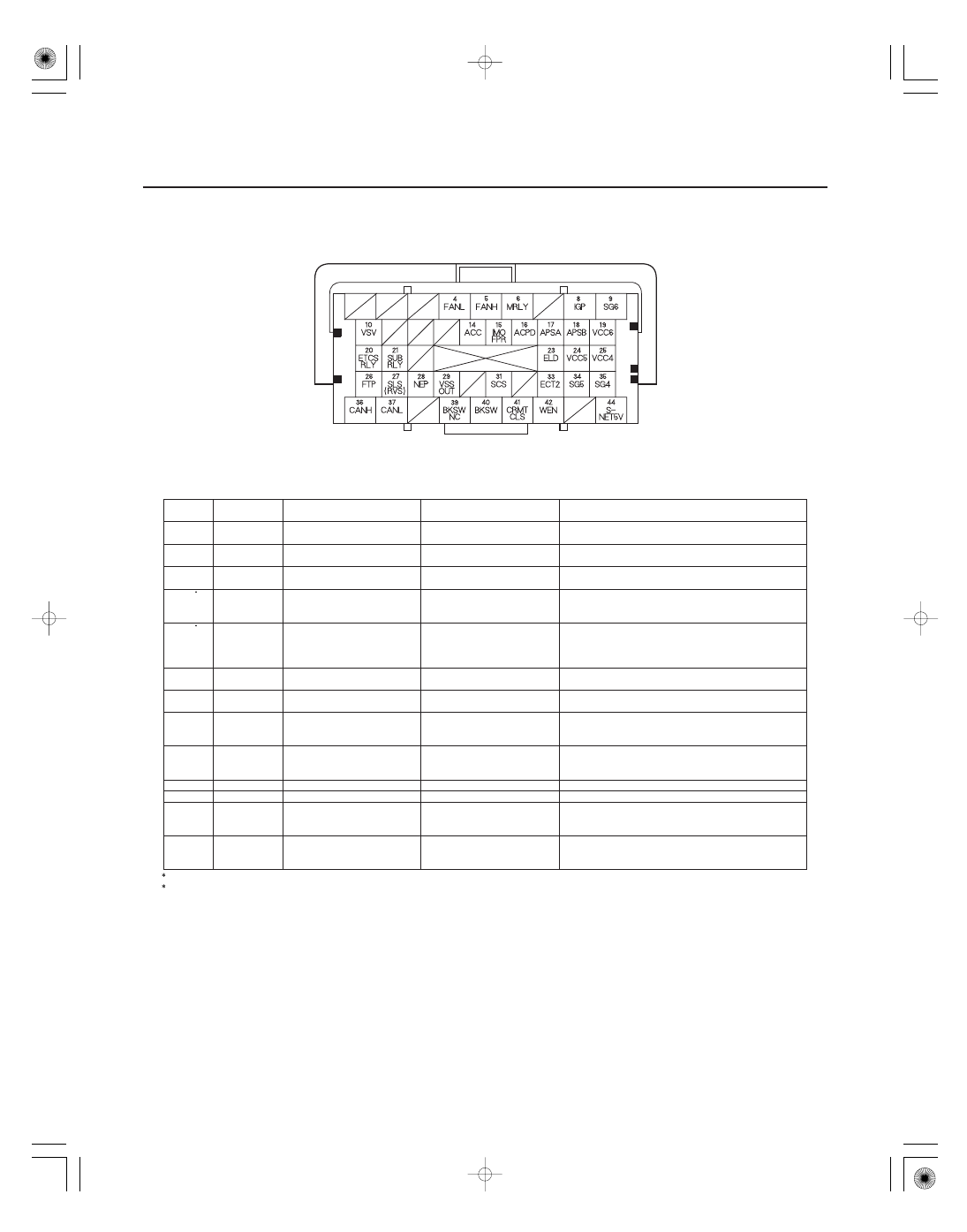
ECM/PCM Inputs and Outputs at Connector A (
) (44P)
Terminal
number
Wire color
Terminal name
Description
Signal
11-26
Fuel and Emissions Systems
NOTE: Standard battery voltage is about 12 V.
24
GRY
VCC5 (SENSOR VOLTAGE)
Provides sensor reference
voltage
With ignition switch ON (II): about 5.0 V
25
BRN
VCC4 (SENSOR VOLTAGE)
Provides sensor reference
voltage
With ignition switch ON (II): about 5.0 V
26
LT GRN
FTP (FUEL TANK
PRESSURE (FTP) SENSOR)
Detects FTP sensor signal
With ignition switch ON (II) and fuel fill cap
removed: about 2.5 V
27
PNK
SLS (SHIFT LOCK
SOLENOID)
Drives shift lock solenoid
With ignition switch ON (II), in P, brake pedal
pressed, and accelerator released:
battery voltage
27
GRN
RVS (REVERSE LOCKOUT
SOLENOID)
Drives reverse lockout
solenoid
With vehicle speed below 9 mph (15 km/h):
battery voltage
With vehicle speed above 13 mph (20 km/h):
about 0 V
28
BLU
NEP (ENGINE SPEED
PULSE)
Outputs engine speed pulse
With engine running: pulses
29
BLU
VSSOUT (VEHICLE SPEED
SIGNAL OUTPUT)
Sends vehicle speed signal
Depending on vehicle speed: pulses
31
BRN
SCS (SERVICE CHECK
SIGNAL)
Detects service check signal
With service check signal shorted using HDS:
about 0 V
With service check signal opened: about 5.0 V
33
GRN
ECT2 (ENGINE COOLANT
TEMPERATURE (ECT)
SENSOR 2)
Detects ECT sensor 2 signal
With ignition switch ON (II): about 0.1
4.8 V
(depending on engine coolant temperature)
34
LT BLU
SG5 (SENSOR GROUND)
Sensor ground
Less than 1.0 V at all times
35
BLU
SG4 (SENSOR GROUND)
Sensor ground
Less than 1.0 V at all times
36
WHT
CANH (CAN
COMMUNICATION SIGNAL
HIGH)
Sends communication
signal
With ignition switch ON (II): about 2.5 V (pulses)
37
RED
CANL (CAN
COMMUNICATION SIGNAL
LOW)
Sends communication
signal
With ignition switch ON (II): about 2.5 V (pulses)
1: A/T
3: K20Z3 engine
1
3
Terminal side of female terminals
08/08/21 14:12:43 61SNR030_110_0026