FANUC a Series AC SERVO MOTOR. Description Manual (GFZ-65142E/02) - page 2
B-65142E/02
DESCRIPTIONS FOR THE α series
4. SELECTING A MOTOR
4.1.2
Following the procedure described below, calculate the torque required
for acceleration:
Calculating the
Acceleration Torque
Calculating acceleration
torque : Procedure 1
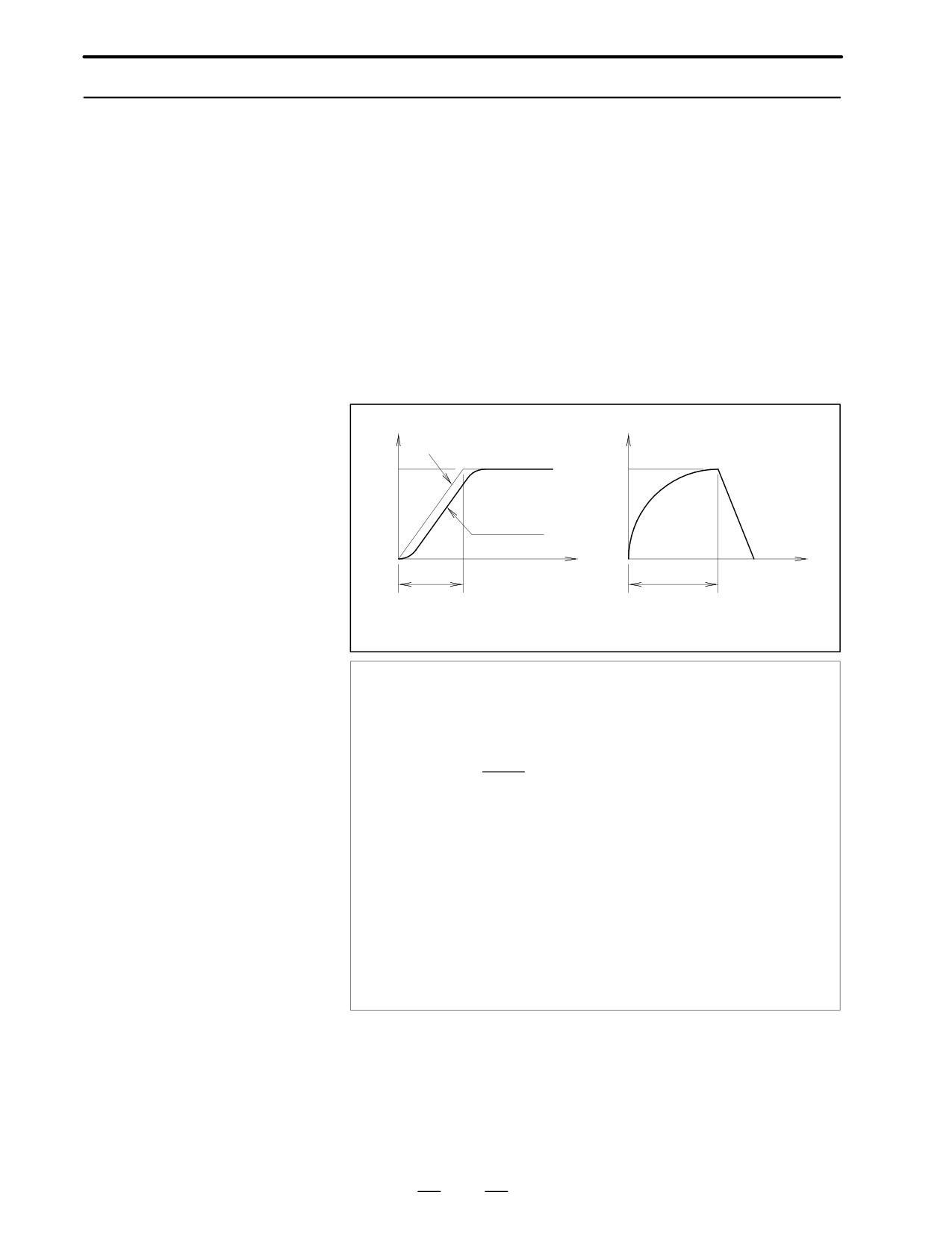
Assuming that the motor shaft operates ideally in the acceleration/
deceleration mode determined by the NC, calculate the acceleration.
Multiply the acceleration by the entire inertia (motor inertia + load
inertia). The product is the acceleration torque. The equation is given
below.
A In linear
acceleration/deceleration
Speed
Torque
Command
Vm
Ta
Operation of
the motor
Time
Vm Speed
ta
Vr
Speed variation
Acceleration required to
achieve the speed
1
Ta +Vm
2C
JM
(1-e-ks@ta)
60
ta
1
)Vm
2C
JL
(1-e-ks@ta) B A
60
ta
1
Vr + Vm
{1-
ta @ ks(1-e-ks@ta)}
Ta
: Acceleration torque (kgf⋅cm)
Vm : Motor speed in rapid traverse (min-1)
ta
: Acceleration time (sec)
JM : Motor inertia (kgf⋅cm⋅sec2)
JL
: Load inertia (kgf⋅cm⋅sec2)
Vr
: Point from which the acceleration torque starts to de-
crease (difference from Vm) (min-1)
ks
: Servo position loop gain (sec-1)
η
: Machine tool efficiency
27
4. SELECTING A MOTOR
DESCRIPTIONS FOR THE α series
B-65142E/02
Example)
Try to perform linear acceleration/deceleration under the following
condition.
When α2/3000 is used, the load inertia is calculated as follows. First
select the α2/3000 and calculate its acceleration torque. JM motor
inertia is 0.0061 (kgf⋅cm⋅s2), Vm is 3000 (min-1), ta is 0.1 (s), ks is 30
(sec-1), and JL = 0.0247 (kgf⋅cm⋅s2).
3000
1
Ta +
2
0.0061
(1-e-30
0.1)
60
0.1
1
)3000
2
0.0247
(1-e-30
0.1) B 0.9
60
0.1
+ 100.1(kgf @ cm) + 9.81(Nm)
Torque (Nm)
Torque (Nm)
12.1 (Nm)
2049 (min-1)
Speed (min-1)
Speed (min-1)
Speed-torque characteristics of
Speed-torque characteristics of
α2/3000
α3/3000
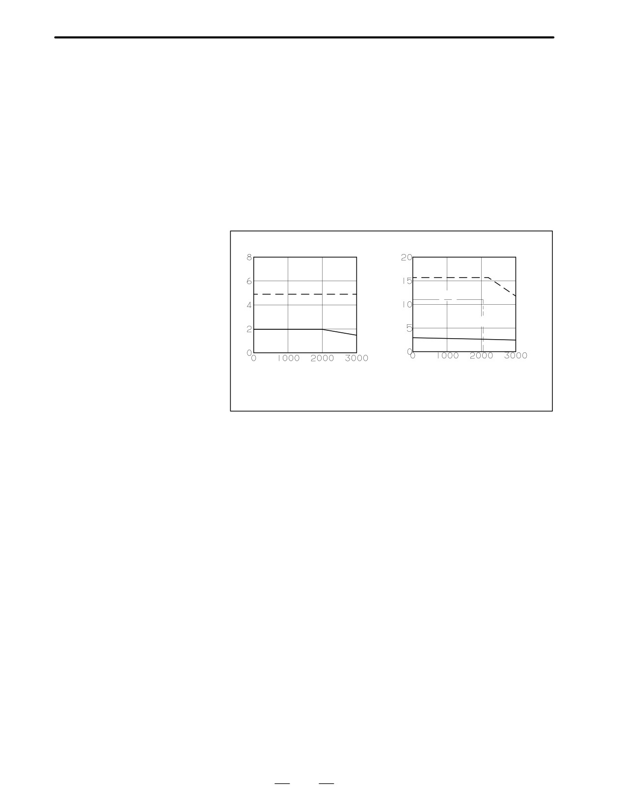
The speed-torque characteristics of α2/3000 show that the acceleration
torque of 9.81 (Nm) is beyond the intermittent operating zone of α2/3000
(see the characteristic curve above and data sheet).
(The torque is
insufficient for α2/3000.)
If the operation specifications of the shaft (for instance, the acceleration
time) cannot be changed, a larger motor must be selected. Select an
α3/3000 (JM is 0.02 (kgf⋅cm⋅s2)) and calculate the acceleration torque
again.
Ta = 123.7 (kg⋅cm) = 12.1 (Nm)
Vr = 2049 (min-1)
In acceleration, an acceleration torque of 12.1 (Nm) is required at 2049
(min-1). The speed-torque characteristic curve shown above shows that
the acceleration is possible with α3/3000.
As α2/3000 is changed to α3/3000, the size of the attachment flange is
increased from 90 mm x 90 mm to 130 mm x 130 mm. If the machine
tool does not allow a larger motor, the specifications must be changed.
For example, the acceleration time must lengthen.
28
B-65142E/02
DESCRIPTIONS FOR THE α series
4. SELECTING A MOTOR
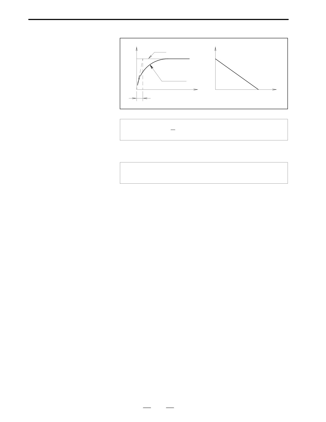
A When acceleration/
deceleration is not
Speed
Torque
controlled
Command
Vm
Ta
Operation of
the motor
Time
Vm Speed
ta
Assume these equations.
1
Ta EVm
,
ta E
60A2p
taA(JM CJL)
ks
Calculating acceleration
To obtain T (torque) required by the motor shaft, add Tm (friction torque)
torque : Procedure 2
to Ta acceleration torque.
TETa CTm
T=12.1(Nm)+0.9(Nm)=13.0(Nm)
Calculating acceleration
Check that T obtained in Procedure 2 above is smaller than or equal to the
torque : Procedure 3
torque limit determined by the amplifier. Using the speed-torque
characteristic curve on the data sheet of the corresponding motor, check
that T obtained in Procedure 1 above is within the intermittent operating
zone at Vr.
As Vr is 2049 (min-1) and T is 13.0 (Nm), the acceleration is possible with
the specified time constant (condition 2).
29
4. SELECTING A MOTOR
DESCRIPTIONS FOR THE α series
B-65142E/02
4.1.3
Calculating the
Root-mean-square
Value of the Torques
Calculating the
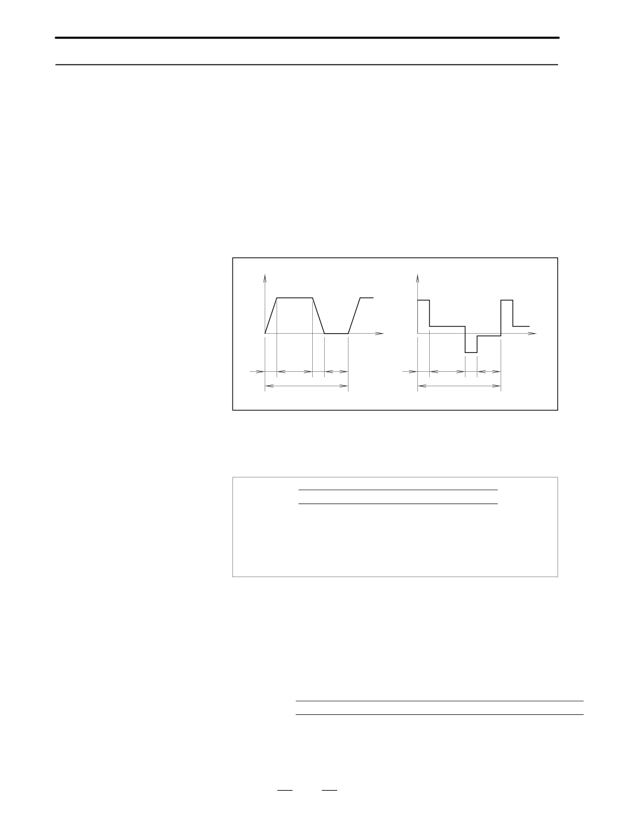
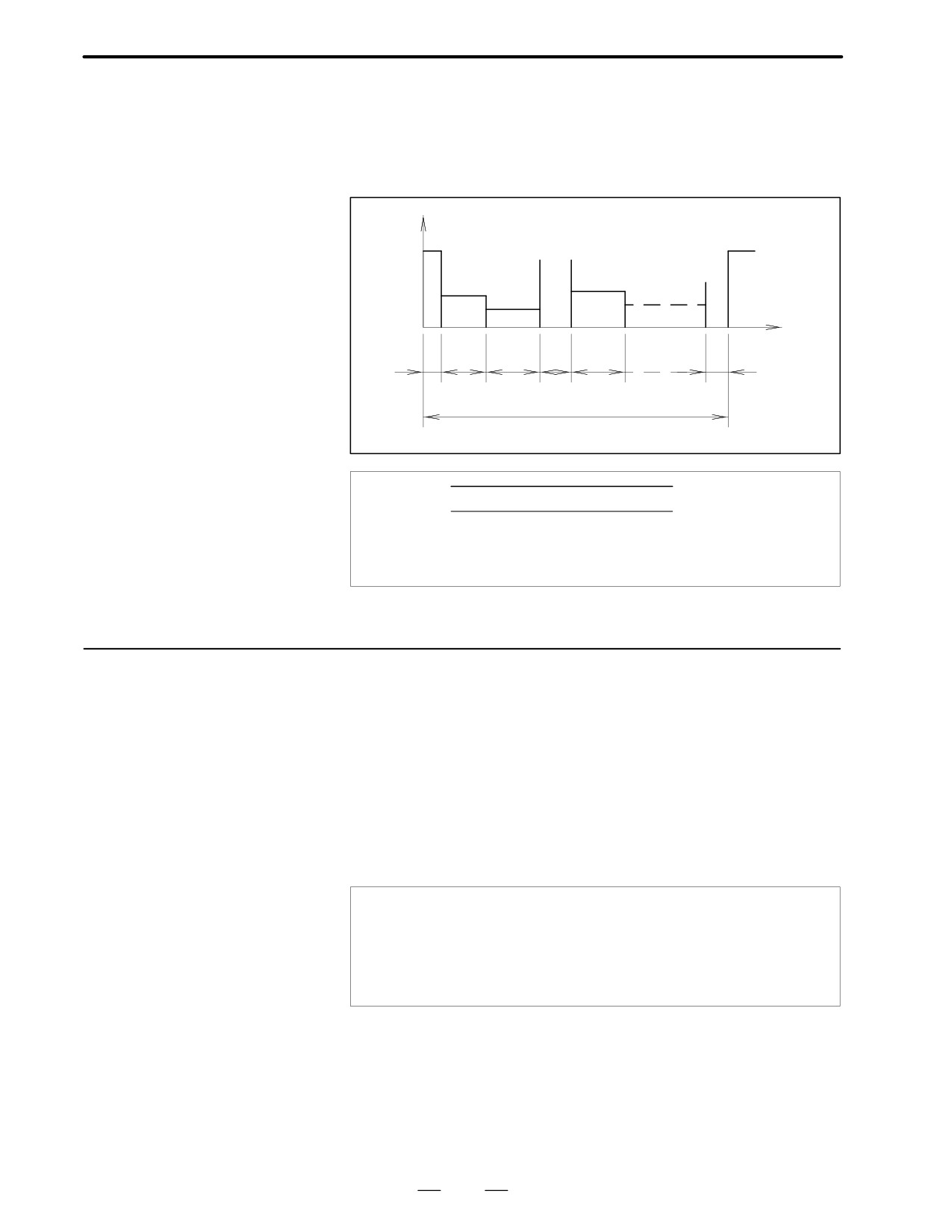
Generate an operation cycle which includes rapid traverse. Write the
frequency of positioning
time-speed graph and time-torque graph as shown below.
in rapid traverse
In a common cutting machine, the frequency of positioning in rapid
traverse will cause no problems. In a special machine tool which
frequently executes rapid traverse, however, the motor must be checked
to see whether it is overheated by the current required for acceleration or
deceleration.
Speed
Torque
Ta+Tf
Tf
To
Time
Ta-Tf
Time
t1
t2
t1
t3
t1
t2
t1
t3
to
to
From the time-torque graph, obtain the root-mean-square value of
torques applied to the motor during the single operation cycle. Check
whether the value is smaller than or equal to the rated torque (condition
3).
(Ta ) Tm)2t1 ) Tm2t2 ) (Ta-Tm)2t1 ) To2t3
Trms +
Ǹ
tO
Ta
: Acceleration torque
Tm : Friction torque
To
: Torque when stopped
If Trms is smaller than or equal to the rated torque at stall (Ts), the motor
can be used.
(Set a value equal to 90% of the static rated torque, considering the total
thermal efficiency.)
Example)
When an α3/3000 (Ts = 31 (kgf⋅cm) = 3.0 (Nm)) is used under the
following conditions: Ta = 12.1 (Nm), Tm = To = 0.9 (Nm), t1 = 0.1
(s), t2 = 1.8 (s), t3 = 7.0 (s)
(12.1 ) 0.9)2
0.1 ) 0.92
1.8 )
(12.1-0.9)2
0.1 ) 0.92
7
Trms +
Ǹ
tO
+ 20.2(Nm) t Ts
0.9 + 2.9
0.9 + 2.61(Nm)
The α3/3000 can be used for operation. (Condition 3)
30
B-65142E/02
DESCRIPTIONS FOR THE α series
4. SELECTING A MOTOR
Calculating the torque in
If the load conditions (cutting load, acceleration/deceleration conditions,
a cycle in which the load
etc.) vary widely in a single cycle, write a time-torque graph according
varies
to the operation cycle, as in above item. Obtain the root-mean-square
value of the torques and check that the value is smaller than or equal to
the rated torque (condition 4).
Torque
T1
T4
Tn
T5
T2
T3
Time
t1
t2
t3
t4
t5
tn
to
T12t1 ) T22t2 ) T32t3 )AAA ) Tn2tn
Ǹ
Trms +
to
to = t1 + t2 + … + Tn
4.1.4
Check that the time for which the table can be moved with the maximum
cutting torque, Tmc, (percentage duty cycle and ON time) is within a
Calculating the
desired range of cutting time. (Condition 5)
Percentage Duty Cycle
If Tmc (maximum load torque) applied to the motor shaft during cutting,
with the Maximum
which is obtained in Subsec. 4.1.1, is smaller than the product of rated
Cutting Torque
torque at stall of the motor (Tc) and α (thermal efficiency), the motor can
be used in continuous cutting. If Tmc is greater than the product (Tmc
> Tc _ α), follow the procedure below to calculate the percentage ratio of
time (tON) Tmc can be applied to the motor to total time (t) of a single
cutting cycle.
(α is assumed to be 0.9. Calculate the percentage
considering the specifications of the machine.)
Tmc t Tc a AAA Operation can be continued with the maximum
cutting torque.
(The percentage duty cycle with
the maximum cutting torque is 100%.)
Tmc u Tc a AAA Calculate the percentage duty cycle, according
to the following figure and expressions.
Example)
As calculated in Subsec. 4.1.1,
Tmc = 21.8 (kgf⋅cm) = 2.1 (Nm)
OS: Tc = 30 (kgf⋅cm) = 2.9 (Nm)
2.9 _ 0.9 = 2.6 (Nm) > 2.1 (Nm) = Tmc
No problems will occur in continuous cutting.
31
4. SELECTING A MOTOR
DESCRIPTIONS FOR THE α series
B-65142E/02
Calculating the
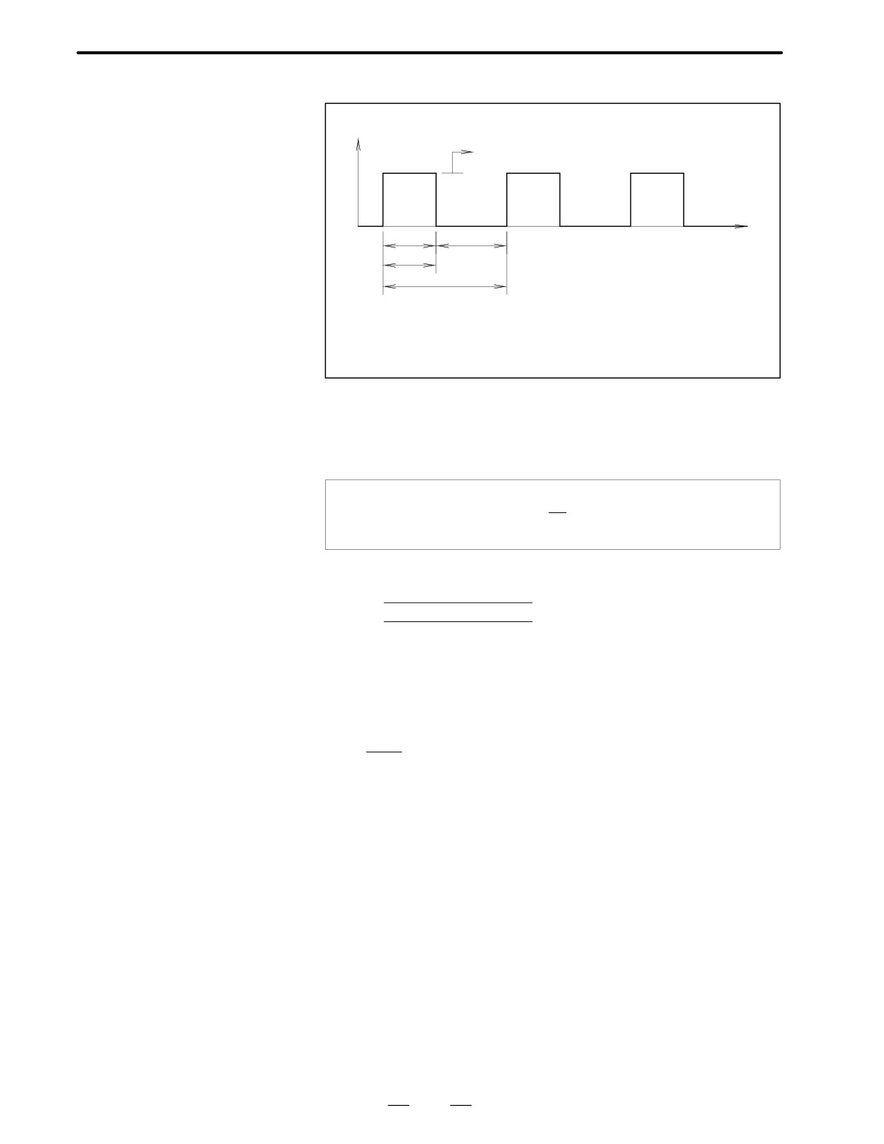
percentage duty cycle
Torque
with the maximum
Maximum cutting torque (Tmc)
cutting torque
ON
OFF
Time
tON
t
t ON
: Time maximum cutting torque (Tmc) is applied
t OFF
: Time no cutting torque is applied
t
: Maximum time of a single cutting cycle
Calculate the root-mean-square value of torques applied in a single
cutting cycle as described in Subsec 4.1.3. Specify tON and tOFF so that
the value does not exceed the product of rated torque at stall of the motor
(Tc) and thermal efficiency (α). Then, calculate the percentage duty cycle
with the maximum cutting torque as shown below.
Percentage duty cycle with the
tON
+
100(%)
maximum cutting torque (Tmc)
T
Example)
Assume that Tmc is 4.0(Nm) (Tm = 0.9(Nm)).
4.02
tON ) 0.92 tOFF
Ǹ
t 2.6(Nm)
tON ) tOFF
Therefore,
tON
1
tOFF t
1.6
The ratio of non-cutting time to cutting time must be 1.6 or greater.
The percentage duty cycle is calculated as follows:
tON
100 + 38.5%
2.6tON
Finally, the α3/3000 that satisfies conditions 1 to 5 is selected.
32
B-65142E/02
DESCRIPTIONS FOR THE α series
4. SELECTING A MOTOR
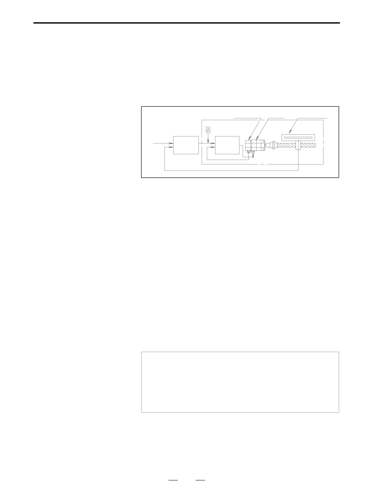
In the case where the machine moves in a linear direction and movement
4.2
is directly detected by linear scale such as inductosyn, magne-scale etc.,
PRECAUTIONS FOR
special considerations are necessary in comparison with the method
USING LINEAR
where feedback is produced by detecting the motor shaft rotation. This
SCALE
is because the machine movement now directly influences the
characteristics of the control system.
Machine system natural
frequency
Pulse coder Motor
Linear scale
Command
Position
Servo
control
amplifier
circuit
This method is shown in the figure above by block diagram. The response
of this control system is determined by the adjustment value (position
loop gain) of the position control circuit. In other words, the position loop
gain is determined by the specified response time of the control system.
In the diagram above, the section enclosed by the broken line is called the
velocity loop. Unless the response time of this section where position
signal is detected is sufficiently shorter than the response time determined
by the position loop gain, the system does not operate properly. In other
words, when a command signal is put into point A, response time of the
machine where position signals are detected must be sufficiently shorter
than the response time defined by the position loop gain.
When the response of the detector section is slow, the position loop gain
must be reduced to have the system operate normally, and as a result, the
response of the whole system is slow. The same problem is caused when
inertia is great (see section 4.1, item 1)).
The main causes for slow response are the mass of the machine and the
elastic deformation of the machine system. The larger the volume, and
the greater the elastic deformation, the slower the response becomes.
As an index for estimating the response of this machine system, the
natural frequency of the machine is used, and this is briefly calculated by
the following equation.
1
m
Wm +
JL
Wm : Natural frequency
JL
: Load inertia reflected to motor shaft (kgf⋅cm⋅s2)
Km : Rigidity of machine system (kgf⋅cm/rad)
=Torque necessary to elastically deform 1 rad at the motor
shaft when the machine table is clamped.
The above values can be obtained by calculating the elastic deformation
for each section of the driving system. If the value of this natural
frequency (Hz) is more than the value of position loop gain (see-1), it
operates normally in most cases. That is to say, when setting 20 sec-1 as
the value of position loop gain, natural frequency of machine system must
be more than 20 Hz. In this case, attention must be paid to the fact that
33
4. SELECTING A MOTOR
DESCRIPTIONS FOR THE α series
B-65142E/02
response becomes a problem for extremely small amounts of movement.
Consequently, the natural frequency should be calculated from the
rigidity at extremely small displacement such as less than 10 µm.
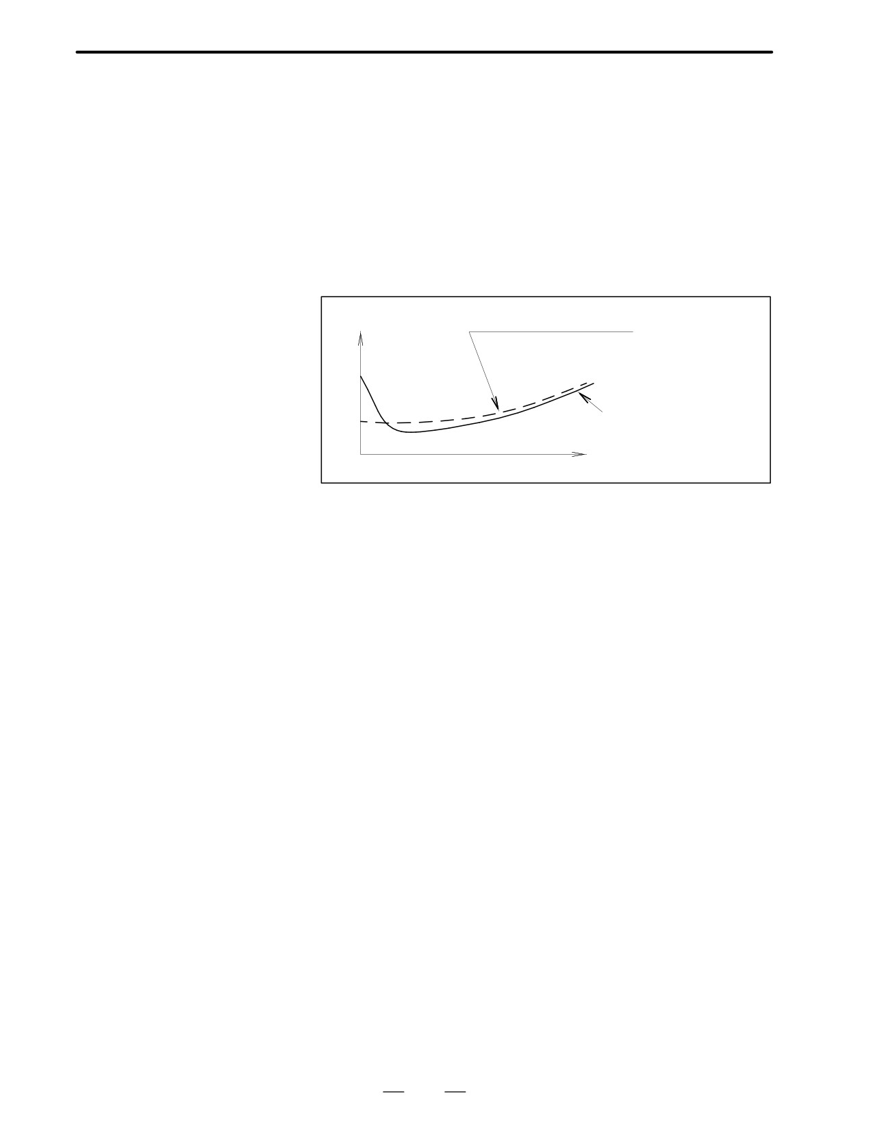
Stick slip
If machine movement causes a stick slip, the control system does not
operate normally. That is, it does not stop where it is supposed to, but a
phenomenon occurs where it goes beyond and then back within an
extremely small range (hunting). To avoid stick slip, the machine rigidity
should be increased, or friction characteristics of the sliding surface
should be improved. When the sliding surface friction characteristic is
as in the figure below, stick slip occurs easily.
Friction coefficient
Proper friction characteristic
Friction characteristic
which causes stick slip
Speed
Value of machine
When the machine is floated by static pressure, etc., there are cases where
overrun
the machine keeps on moving within the range of backlash although the
(Damping coefficient of
motor shaft has stopped. If this amount is large, hunting will also occur.
To avoid this, backlash should be reduced (especially the backlash of the
machine system)
last mass where position detector is mounted) and the appropriate
damping should be considered.
34
B-65142E/02
DESCRIPTIONS FOR THE α series
4. SELECTING A MOTOR
Select a suitable motor according to the load condition, rapid traverse rate,
4.3
increment system, and so on. To aid in selecting the correct motor, fill out
MOTOR SELECTION
the ”servo motor selection data table” at the end of this section.
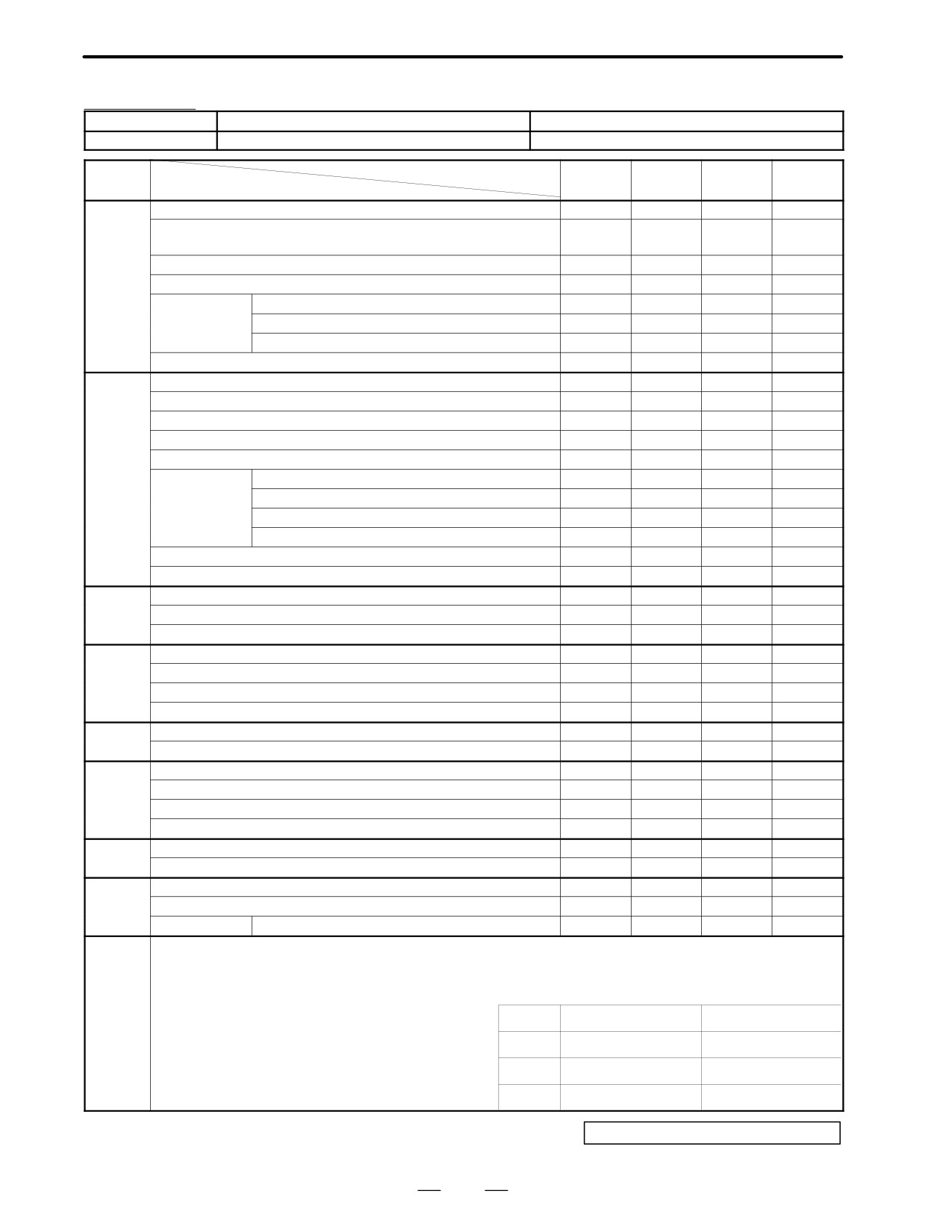
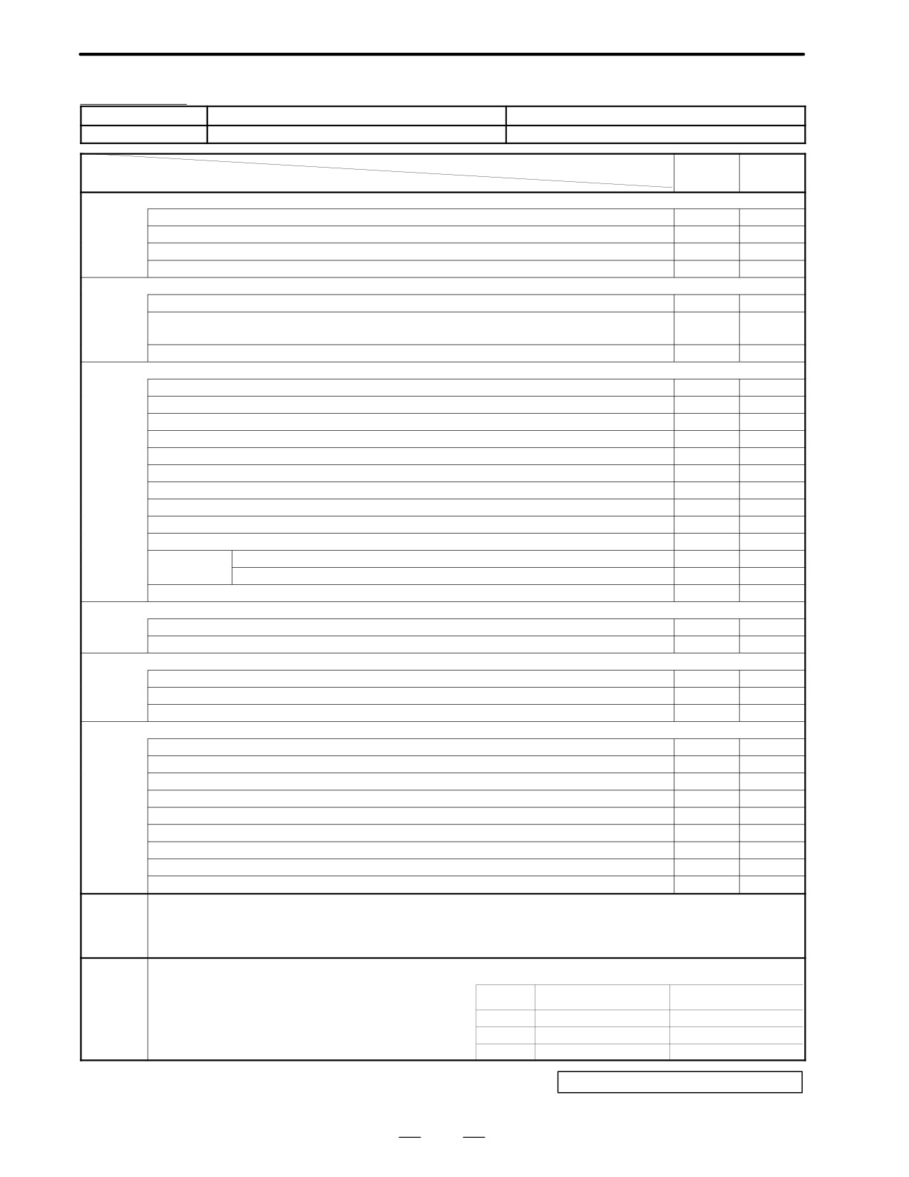
Fill in blanks of machine tool data items (No. 1, 2 and 3) of this table with
necessary data, and send this table to our representative.
The representative will fill in blanks of item No. 4 to 8 with suitable data
of motor and send this table back.
Details of each item in this selection data table are as described in Subsec.
4.3.1 and 4.3.2.
4.3.1
Blanks for Those Other
than Data
Kind of machine tool
Fill in this blank with a general name of machine tools, such as lathe,
milling machine, machining center, and others.
Type of machine tool
Fill in this blank with the type of machine tool decided by machine tool
builder.
CNC equipment
Fill in this blank with the name of CNC (15T, 16M, 0MC, etc.) employed.
Spindle motor output
Fill in this blank for reference when examining the servo motor output.
Names of axes
Fill in this blank with names of axes practically employed in CNC
command. If the number of axes exceeds 4 axes, enter them in the second
sheet.
Blanks of version
These blanks are left blank by the FANUC.
number, date, name, and
reference number.
4.3.2
Machine tool builders are requested to fill in data blanks No. 1, 2, 3. Fill
in No. 4 items and higher blanks with decided values or desired values,
Data
if any, from the viewpoints of specifications.
If these values are unknown or undecided, the representative will decide
these values according to the contents in item No. 1, 2, and 3. So leave
them blank. See the following for details of the contents of filling in.
No. 1 blank
Data in this blank are used for determining approximate values of motor
load conditions (inertia, torque). Fill in blanks of all items.
Enter the movement directions of driven parts such as table, tool post, etc.
A Axis movement direction
Write the angle from the horizontal level, if their movement directions are
slant (Example : Slant 60°)
Whether their movement directions are horizontal or vertical (or slant) is
necessary for calculating the regenerative energy. Fill in this blank
without fail.
Enter the weight of driven parts, such as table , tool post, etc. by the
A weight of driven parts
maximum value including the weight of workpiece, jig, and so on. Do
not include the weight of the counter balance in the next item in this item.
35
4. SELECTING A MOTOR
DESCRIPTIONS FOR THE α series
B-65142E/02
A Counter balance
Enter the weight of the counter balance in the vertical axis, if provided.
Write the force in case of hydraulic balance.
A Table support
Enter the type of table slide as to rolling, sliding, or static pressure type.
If a special slide way material like Turcite is used, note it.
A Feed screw
Enter the diameter, pitch, and axial length of the lead screw in order.
A Total gear ratio
Enter the gear ratio between the ball screw and the servo motor, gear ratio
between the final stage pinion and the servo motor in case of the rack
pinion drive, or gear ratio between the table and the motor in case of rotary
table.
No. 2 blank
Data in this blank serve as the basis for selecting the motor. Enter these
data correctly. For details of calculating methods of respective items,
refer to sec. 4.1 and 4.2.
A Movement per rotation of
Enter the movement of the machine tool when the motor rotates one turn.
motor
Example
A When the pitch of ball screw is 12 mm and the gear ratio is 2/3,
12
2/3 = 8 mm
A When the gear ratio is 1/72 in rotary table ;
360
1/72 = 5 deg
A Least input increment
Enter the least input increment of NC command. The standard value is
CNC
0.001 mm in Series 0, 15, 16, and 18 CNCs.
A Rapid traverse rate and
Enter the rapid traverse rate and cutting feedrate required for machine tool
cutting feedrate
specifications.
A Inertia
Enter a load inertia value reflected to the motor shaft. For details of this
calculation, see Subsec. 4.1.1.
It is not always necessary to enter this inertia value in detail.
Enter it as a 2-digit or 1-digit value. (Example : 0.2865³0.29 or 0.3)
Do not include any inertia of the motor proper in this value.
A Load torque
A Since the torque produced in low speed without cutting may be applied
even during the stop of motor, a sufficient allowance is necessary as
compared with the continuous rated torque of the motor. Suppress this
load torque to be lower than 70% of the rated torque.
A For the torque during rapid traverse, enter the torque during traveling
at rapid traverse steady-state speed.
Keep this value within the continuous rating. Do not include any
torque required for acceleration/deceleration in this item.
A For the cutting torque, enter the maximum value of the force being
applied during cutting by the force in the feed axis direction.
A For the maximum cutting torque, enter the torque value on the motor
shaft corresponding to the maximum value of the above cutting thrust.
Since the torque transfer efficiency may substantially deteriorate to a
large extent due to the reaction from the slide way, etc. produced by
the cutting thrust, obtain an accurate value by taking measured values
in similar machine tools and other data into due account.
A If the load torque values differ during lifting and lowering in the
vertical axis, enter both values.
36
B-65142E/02
DESCRIPTIONS FOR THE α series
4. SELECTING A MOTOR
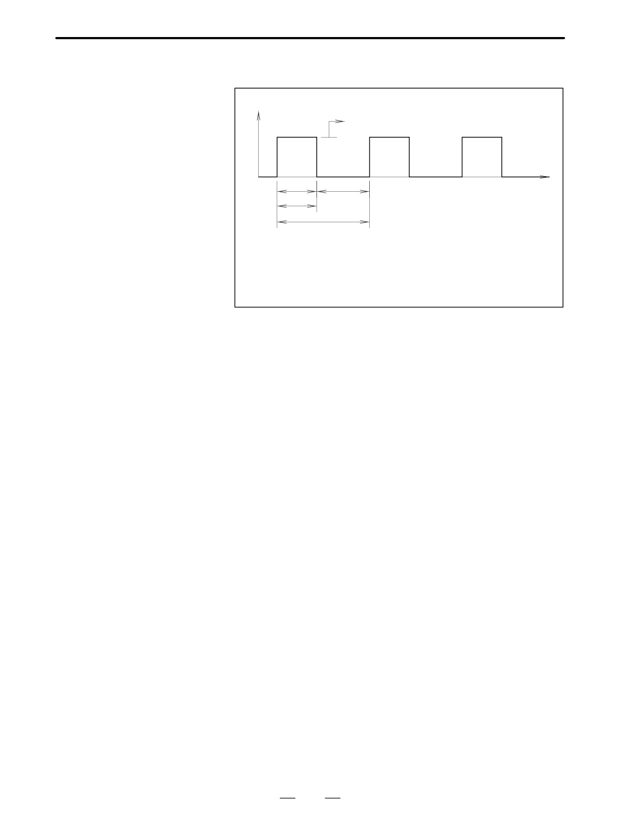
A Maximum cutting duty /
Enter the duty time and ON time with the maximum cutting torque in item
ON time
“Load torque” applied. These values mean as follows.
Torque
Maximum cutting torque (Tmc)
ON
OFF
Time
t
T
ON
: Time the maximum cutting torque (Tmc) is being applied.
OFF
: Time absent from the cutting torque
Duty
: t/T
100 (%)
On time = t (min)
A Rapid traverse
Enter the rapid traverse positioning frequency by the number of times per
positioning frequency
minute. This value is used to check if the motor is overheated or not by
a flowing current during acceleration / deceleration or to check the
regenerative capacity of the amplifier.
No. 3 blank
Data in this blank are necessary for examining the stability of the servo
system when the position detector is attached outside the motor. Enter
these data without fail when the servo system is constructed using a linear
scale.
A Separate type position
If the position detector is mounted outside the motor, enter the name of
detector
the detector. Enter the following items in the “remarks” column, if a
rotary detector such as resolver, pulse coder, or the like is used.
A Resolver
Move amount of machine tool per revolution of resolver
Number of wave lengths per revolution of resolver
A Pulse coder
Move amount per revolution of pulse coder
Number of pulses of pulse coder
A Rigidity of feed system
Enter the relation between the torque and the displacement when the
machine tool
torque is applied to the motor shaft, assuming that the final driven part like
the table has been fully locked. Fill in this value as a torque value required
for the angular displacement of 1 radian.
37
4. SELECTING A MOTOR
DESCRIPTIONS FOR THE α series
B-65142E/02
Example)
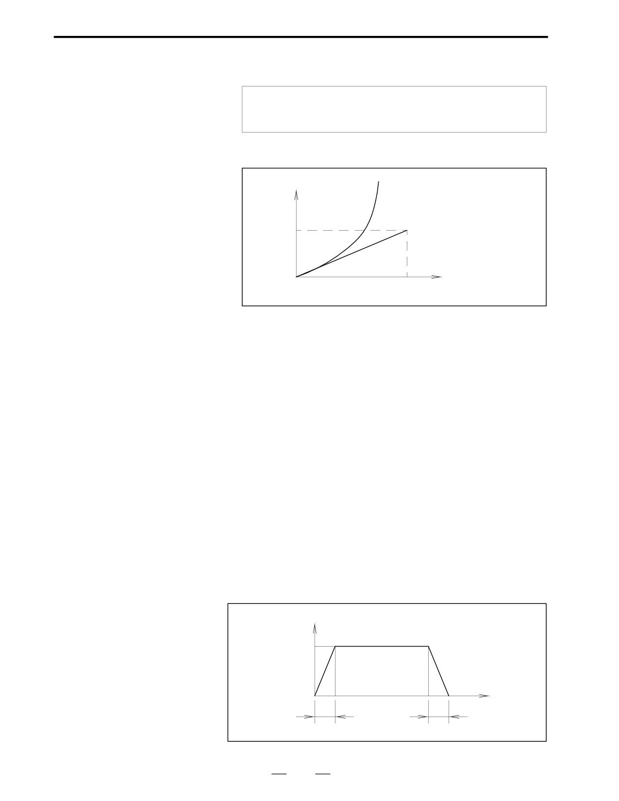
If displacement of 5 deg. at 500 kgf⋅cm torque as a calculation results,
500
180
Rigidity +
+ 5730kgf @ cmńrad
5
p
If the relation between the displacement and the torque is nonlinear,
calculate the rigidity by the gradient in the vicinity of origin.
Torque
(Nm)
Rigidity +T
e (Nmńrad)
T
e
Displacement (rad)
A Backlash amount
Enter the backlash amount between the motor and the final driven part like
table by converting it into the move amount of the table.
No. 4 blank
Motor specifications
A Motor model
Enter the model name of the motor employed and the specifications of the
Feedback (FB) type
built-in feedback unit by using symbols.
A Option, special
Enter special specifications, if any, in this blank.
specifications
No. 5 blank
The acceleration / deceleration time in this item is a commanded value.
It does not mean any actual completion time of positioning.
A Acceleration /
The acceleration/deceleration time is determined according to the load
deceleration time at
inertia, load torque, motor output torque, and working speed. For details
rapid traverse
of calculations, refer to Subsec. 4.1.2 and 4.1.3.
The acceleration/deceleration mode at rapid traverse is generally linear
acceleration/deceleration in FANUC’s CNC.
Speed
Vm
Time
ta
ta
38
B-65142E/02
DESCRIPTIONS FOR THE α series
4. SELECTING A MOTOR
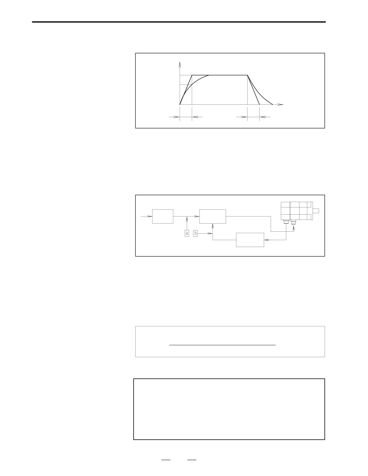
A Acceleration/
The acceleration/deceleration at cutting feed is exponential acceleration
deceleration time at
/deceleration in general. This blank is filled in with its time constant
cutting feed
Speed
Vm
0.632Vm
Time
te
te
te : Time constant
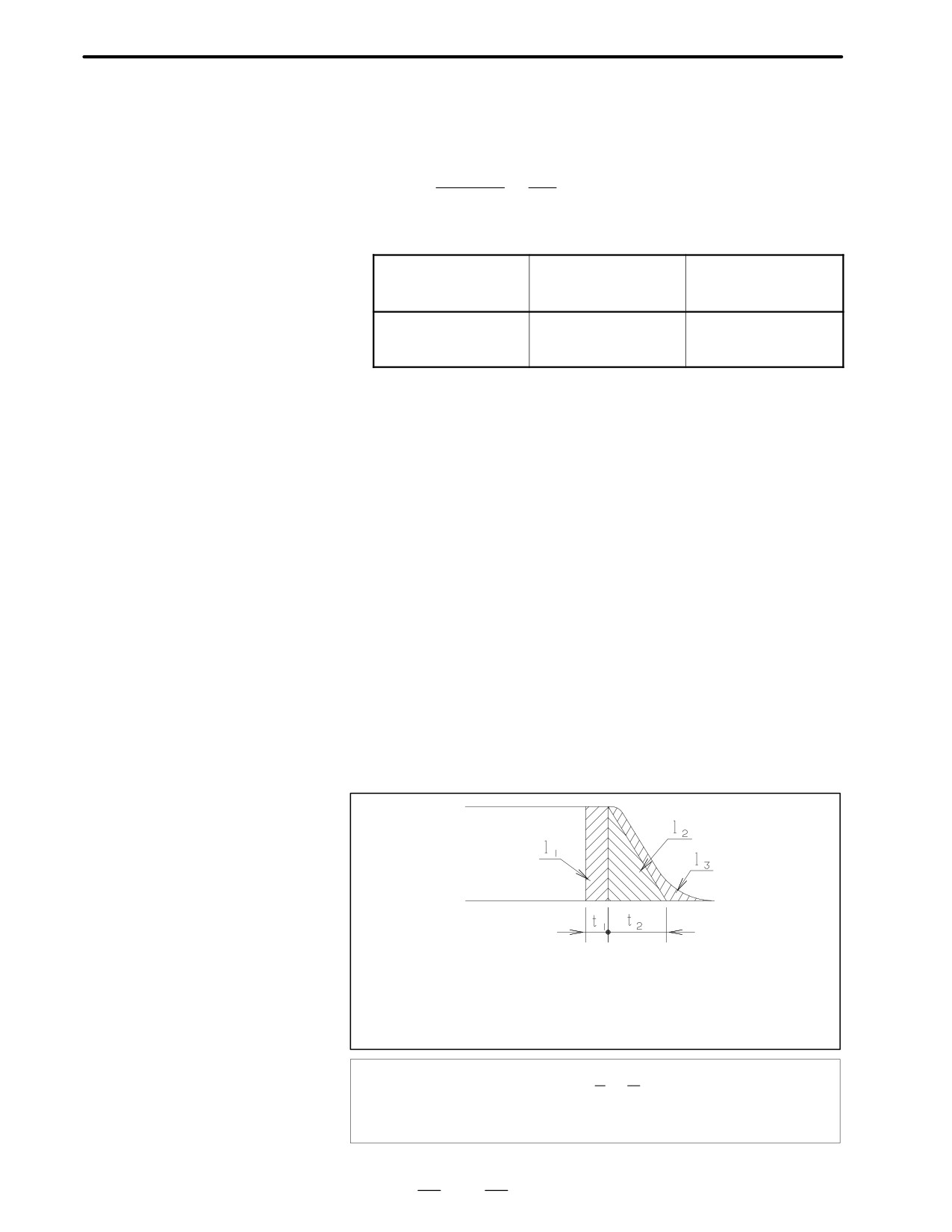
No. 6 blank
A Input multiply ratio,
The NC set values required for moving the machine tool at the least input
command multiply ratio,
increment values are entered in these blanks.
and flexible feed gear
The relation among these values as illustrated below.
ratio
Command multiply ratio
Error
CMR
register
Flexible
feed gear
In the above figure, each ratio is set so that the units of the two inputs (a
and b) of the error register are the same. The pulse coder uses a flexible
feed gear as standard. So, CMR is normally set to 1. When other than
1 is to be set for CMR, contact FANUC for details.
For the flexible feed gear (F.FG), the ratio of the number of position pulses
required per motor shaft revolution to the number of feedback pulses is
set. The set value is obtained as follows:
Number of position pulses required
per motor shaft revolution
F.FG +
1,000,000
Note
For calculation, the number of feedback pulses for the α
pulse coder must always be set to
1,000,000.
The
maximum permissible value for both the numerator and
denominator is 32,767. So, the fraction should be reduced
to its lowest terms, after which the resultant numerator and
denominator should be set.
39
4. SELECTING A MOTOR
DESCRIPTIONS FOR THE α series
B-65142E/02
Example)
Suppose that the NC uses increments of 1 m, the machine travel
distance per motor shaft revolution is 8 mm, and pulse coder A64 is
used.
8, 000
1
F.FG E
CMR E 1
1, 000, 000E
125,
Setting F.FG when 1 µ m detection is performed using the semi-closed
loop
Machine travel dis-
Number of required
tance per motor shaft
position pulses
F.FG value
revolution (mm/rev)
(pulses/rev)
10
10000
1/100
20
20000
2/100 or 1/50
30
30000
3/100
A Position loop gain
Fill in this blank with a value which is considered to be settable judging
it from the inertia value based on experiences.
Since this value is not always applicable due to rigidity, damping
constant, and other factors of the machine tool, it is usually determined
on the actual machine tool. If the position detector is mounted outside the
motor, this value is affected by the machine tool rigidity, backlash
amount, and friction torque value. Enter these values without fail.
No. 7 blank
The coasting distance of the machine tool at the machine tool stroke end
is entered in this blank. The stroke end is usually limited in 2 steps
consisting of the deceleration stop in the first step and dynamic brake stop
in the second step.
The position display accurately coincides with the stop position of the
machine tool when the first step limit switch is depressed. However, this
position is lost when the second step limit switch is depressed. Mount this
second limit switch without fail for preventing the machine tool from
being damaged, because it is only one means of stopping the machine
tool, if the machine tool should run away due to a control failure.
A Deceleration stop
Enter the coasting distance when the machine tool is decelerated and
distance
stopped at the stroke end.
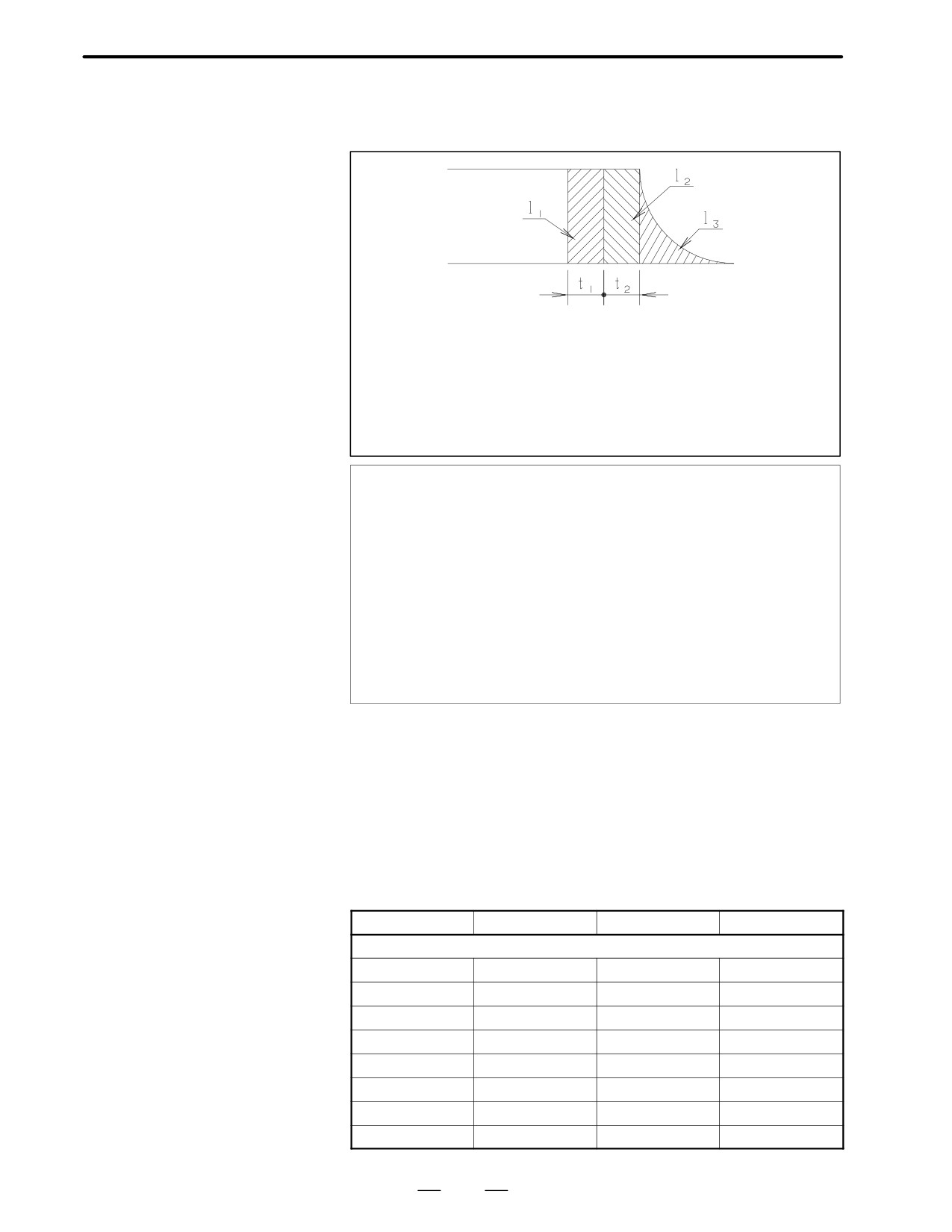
Vm
Vm : Rapid traverse rate, mm/min or deg /min
l1
: Coasting distance due to delay time t1 of receiver
l2
: Coasting distance due to deceleration time t2
l3
: Servo deflection amount
t1
: Usually about 0.02 seconds
t2
Coasting distance EVm
60A(t1 C
2
ks
ks : Position loop gain (sec-1)
40
B-65142E/02
DESCRIPTIONS FOR THE α series
4. SELECTING A MOTOR
A Dynamic brake stop
This is coasting distance when the machine tool is stopped by dynamic
distance
braking with both ends of the motor power line shorted, if the machine
tool is in trouble.
Vm
Vm : Rapid traverse rate, mm/min or deg /min
l1
: Coasting distance due to delay time t1 of receiver
l2
: Coasting distance due to deceleration time t2 of magnetic con-
tactor (MCC)
l3
: Coasting distance by dynamic braking after magnetic contactor
has been operated
(t1+t2) is usually about 0.05 seconds.
Coasting distance(mm or deg)
EVm
t2) C (Jm C J1) A (ANo C BNo3) A L
60A(t1 C
Jm : Motor inertia (kg·cm·s2)
J
: Load inertia (kg·cm·s2)
No : Motor speed at rapid traverse (rpm)
L
: Machine movement on one-rotation of motor (mm or deg)
NoL=Vm
A and B are constants that vary with the model of the motor being used.
The values for each model are listed under ”Coefficients for Calculating
the Dynamic Brake Stopping Distance.”
No. 8 blank
Servo amplifier specification
A Type of amplifier
Designate AC servo.
A Transformer
Fill the transformer specification.
A Specifications
Enter the servo amplifier module specifications.
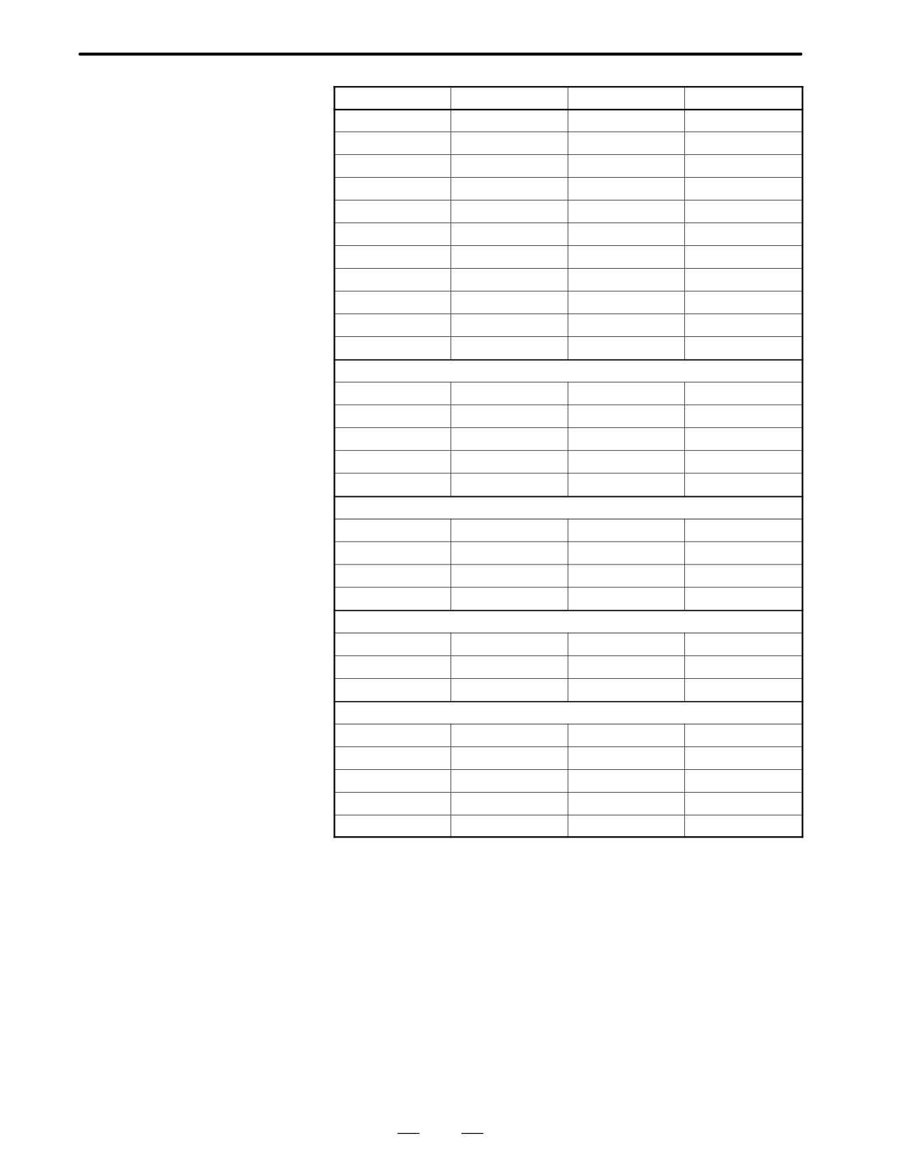
Coefficients for
calculating the dynamic
Model
A
B
Jm (kgf⋅cm⋅s2)
brake stopping distance
α series
α0.5/3000
8.1A10-2
5.9A10-8
0.00018
α1/3000
5.9A10-2
1.3A10-8
0.0037
α2/2000
1.9A10-2
5.3A10-9
0.0061
α2/3000
2.2A10-2
4.6A10-9
0.0061
α3/3000
1.4A10-2
7.3A10-9
0.014
α6/2000
5.5A10-3
4.4A10-9
0.027
α6/3000
1.1A10-2
2.1A10-9
0.027
α12/2000
3.0A10-3
6.8A10-9
0.064
41
4. SELECTING A MOTOR
DESCRIPTIONS FOR THE α series
B-65142E/02
Model
A
B
Jm (kgf⋅cm⋅s2)
α12/3000
6.7
10-3
3.1
10-9
0.064
α22/1500
1.5
10-3
3.3
10-9
0.12
α22/2000
2.8
10-3
1.8
10-9
0.12
α22/3000
4.2
10-3
1.2
10-9
0.12
α30/1200
8.6
10-4
2.5
10-9
0.17
α30/2000
1.1
10-3
2.0
10-9
0.17
α30/3000
2.5
10-3
8.6
10-10
0.17
α40/2000
1.1
10-3
1.1
10-9
0.23
α65/2000
1.7
10-3
4.2
10-10
0.19
α100/2000
1.3
10-3
2.4
10-10
0.27
α150/2000
1.0
10-3
1.7
10-10
0.35
α(HV) series
α3/3000HV
3.4
10-2
3.0
10-9
0.014
α6/3000HV
1.3
10-2
1.8
10-9
0.027
α12/3000HV
1.4
10-2
1.5
10-9
0.064
α22/3000HV
7.8
10-3
6.4
10-10
0.12
α30/3000HV
4.3
10-3
5.0
10-10
0.17
αC series
αC3/2000
8.3
10-3
1.3
10-8
0.014
αC6/2000
2.7
10-3
8.8
10-9
0.027
αC12/2000
1.4
10-3
1.5
10-8
0.064
αC22/1500
1.5
10-3
3.3
10-9
0.12
αM series
αM3/3000
2.0
10-2
7.1
10-9
0.008
αM6/3000
9.7
10-3
2.7
10-9
0.014
αM9/3000
5.5
10-3
1.0
10-9
0.026
αL series
αL3/3000
2.3
10-2
3.0
10-8
0.0025
αL6/3000
1.4
10-2
1.1
10-8
0.0050
αL9/3000
1.1
10-2
1.9
10-9
0.010
αL25/3000
3.6
10-3
1.6
10-9
0.055
αL50/2000
1.7
10-3
1.1
10-9
0.10
The values of A and B are calculated by assuming that the resistance of
the power line is 0.05 Ω per phase. The values will vary slightly according
to the resistance value of the power line.
Coefficient will vary depending on the servo amplifiers. The machine
may stop by a less distance movement by the coefficient.
42
B-65142E/02
DESCRIPTIONS FOR THE α series
4. SELECTING A MOTOR
MTB
AC servo motor selection data table
Machine
Kind
Type
NC, spindle motor
NC ; FANUC
(
)
Spindle motor
kW
Axis
No.
Item
Axis movement direction (horizontal, vertical rotation)
Weight of moving component parts
(including workpiece, etc.)
kgf
Counter balance
kgf
1
Table support (sliding, rolling, static pressure)
Diameter
Feed screw
Pitch
Axial length
Total gear ratio
Movement of machine tool per revolution of motor
mm
Least input increment of NC
mm
Rapid traverse feedrate
mm/min
Cutting traverse feedrate
mm/min
Inertia
kgf⋅cm⋅sec2
2
Low feed without cutting
kgf⋅cm
Rapid traverse
kgf⋅cm
Load torque
Cutting thrust
kg
Maximum cutting torque
kgf⋅cm
Maximum cutting duty/ON time
%/min
Rapid traverse positioning frequency
times/min
Separate type position detector
3
Feed system machine tool rigidity
kgf⋅cm/rad
Backlash amount
mm
Motor type
FB type
4
Number of rotation at rapid traverse
rpm
Option / Special specifications
Acceleration/deceleration time at rapid traverse
msec
5
Acceleration/deceleration time at cutting feed
msec
Command multiply ratio
CMR
Detection multiply ratio
DMR
6
Flexible feed gear
FFG
Position loop gain
sec-1
Deceleration stop distance
mm
7
Dynamic brake stop distance
mm
Amplifier type
8
Transformer
Specifications
Amplifier
Version
Date
Name
Remarks
1
2
3
FANUC LTD
A. Ar - 1870 -
43
4. SELECTING A MOTOR
DESCRIPTIONS FOR THE α series
B-65142E/02
MTB
Servo motor selection data table (models for positioning)
Machine
Model
NC model
NC ; FANUC
Name
Axis name
Item
Specifications of moving object
Direction of movement (horizontal, vertical, rotation)
Weight of the moving object (including the workpiece)
kgf
Counterbalance
kgf
Table support (sliding contact, rolling contact, static pressure)
(*)
Feed mechanism (Select one of the following and enter the corresponding data.)
1 Ball screw: Diameter _ pitch _ length
2 Rack and pinion: Diameter of pinion (traveling distance of the machine tool per
revolution of the pinion: mm)
3 Others
Mechanical specifications
Traveling distance of the machine tool per revolution of the motor
mm
Total gear reduction ratio
Inertia (Note ”before deceleration” or ”applied to the motor shaft.”)
kgf⋅cm⋅sec2
Least input increment of NC (resolution)
mm
Maximum rapid traverse feedrate
mm/min
Motor speed in rapid traverse
rpm
Acceleration/deceleration time in rapid traverse
msec
Distance of positioning in rapid traverse
mm
Frequency of positioning in rapid traverse
times/min
In the remarks section, note the operation cycle (speed pattern) if it is determined.
Low feed without cutting
kgf⋅cm
Load torque
Rapid traverse
kgf⋅cm
Backlash
mm
Fill in these blanks when an separate type position detector is used.(**)
Type of separate type position detector (detection unit, number of pulses, etc.)
Gear diameter and reduction ratio when a rotary encoder is used
Motor specifications
Motor type (desired size and output, if any)
FB type (when an absolute position detector is required)
Option (when a brake, non-standard shaft, etc. is required)
FANUC will fill in these blanks.
Command multiplier
CMR
Detection multiplier
DMR
Flexible feed gear
FFG
Position loop gain
sec-1
Deceleration stop distance
mm
Dynamic brake stop distance
mm
Specifications of amplifier
Specifications of regenerative discharge unit
Specifications of transformer
(*) Note the friction coefficient of the sliding surface if it is determined.
(**) A separate type position detector is required when:
Note
-The positions of the motor and machine may be mechanically displaced, for example, by slippage of a
driving tire or an elongated driving chain.
Version
Date
Name
Remarks
1
2
3
FANUC LTD
A. Ar - 1870 -
44
B-65142E/02
DESCRIPTIONS FOR THE α series
4. SELECTING A MOTOR
Performance of each motor model is represented by characteristic curves
4.4
and data sheet shown below.
CHARACTERISTIC
CURVE AND DATA
SHEET
The typical characteristic curves consist of the following.
4.4.1
Performance Curves
Speed-torque
These are known as operating curves and describe the relationship
characteristics
between the output torque and speed of the motor. The motor can be
operated continuously at any combination of speed and torque within the
prescribed continuous operating zone. Outside of this zone, the motor
must be operated on an intermittent basis using the duty cycle curves. The
limit of continuous operating zone is determined under the following
conditions. And this zone may be limited by the thermal protection of
mounted precision instrument. (pulse coder)
A The ambient temperature for the motor is 20°C.
A The drive current of the motor is pure sine wave.
The limit of intermittent operating zone is determined by input voltage to
the motor.
Actual operation is limited by the current limit of servo unit.
Due to the negative temperature coefficient of the magnetic material,
continuous operating zone must be derated at the rate of 0.19% per degree
centigrade rise of magnets. (i.e. for ambient temperature above 20° derate
0.19% for each degree over)
Overload duty
These curves are known as duty cycle curves and provided very important
characteristic
information on how to determine the ”ON” time for intermittent overload
torque without overheating the motor. The curves shown in the following
figures are ones determined by the limit of the temperature of the motors.
When the motor is driven by some driving circuit having thermal protect
devices such as thermal relay or fuse, the ”ON” time may be limited by
the characteristics of those elements.
4.4.2
The data sheet gives the values of motor parameters relating to the
performance.
Data Sheet
The values of parameters are those under the following conditions.
A The ambient temperature for the motor is 20°C.
A The drive current of the motor is pure sine wave.
Important parameters on the data sheet are defined as follows :
Continuous RMS current at stall TENV : Is (Arms)
Motor can be operated at this RMS current continuously at stall (or low
speed) with TENV (Totally Enclosed Non Ventilation).
45
4. SELECTING A MOTOR
DESCRIPTIONS FOR THE α series
B-65142E/02
Torque constant : Kt (kgf⋅cm/Arms)
This is known as torque sensitivity and represents the torque
developed per ampere of phase current. This value can usually be
obtained by measuring the torque developed by rated current. The
torque constant is a function of the total flux and the total number of
conductors in the armature.
The back EMF constant and the torque constant are inter-related as
follows :
Kt(kgf @ cmńArms) + 30.6Kv(Volt @ sec ńrad)
Thus if Kv is reduced due to demagnetization of the magnetic field,
Kt is also reduced in the same proportion.
Back EMF (electromotive force) constant: Kv (volt·sec/rad)
The back EMF constant is the indication of the permanent magnet field
strength. It is the value of the generated voltage at a specified speed
when magnetic field is rotated mechanically, and is the function of
total number of conductors in the armature and total flux of the field.
The back EMF constant has the dimensions of volt-second per radian
or volts per rpm. The relationship can be given as :
Volt @ sec
+Volt
9.55
rpm
rad
Back EMF constant is indicated as the RMS voltage per phase, so
Ǹ
multiply
3
to get actual terminal voltage.
Mechanical time constant : tm (sec)
This is a function of the initial rate of rise in velocity when a step
voltage is applied. It is calculated from the following relationship.
Jm @ Ra
tm +
Kt @ Kv
Jm : Rotor inertia (kgf⋅cm⋅s2)
Ra ; Resistance of the armature
Thermal time constant : tt (min)
This is a function of the initial rate of rise of winding temperature at
rated current. It is defined as the time required to attain 63.2 percent
of the final temperature rise.
Static friction : Tf (kg⋅cm)
This is the no-load torque required just to rotate the rotor.
Max. current before demagnetization : Im (A)
This value of current is the instantaneous (peak) current which can be
applied to the motor without demagnetizing the permanent magnet
field. The magnet can be demagnetized even on only one pulse of high
current. Care should therefore be taken to limit peak currents to the
stated value. Repeated pulses at rated peak or less will not affect
demagnetization.
46
B-65142E/02
DESCRIPTIONS FOR THE α series
4. SELECTING A MOTOR
4.4.3
Servo motors can be operated in the range exceeding continuous rated
torque depending on thermal time constant. Duty characteristics shows
How to Use Duty Cycle
the Duty (%) and the ”ON” time in which motor can be operated under
Curves
the given overload conditions. Calculation procedure is as follows.
1
Calculate Torque percent by formula (b) below.
2
Motor can be operated at any point on and inside the curve
corresponding to the given over load conditions obtained form 1.
3
Calculate tF by formula (a)
100
tF + tR a (
(a)
Duty percent-1)
Load torque
(b)
TMD +
Continuous rated torque
tF
:
“OFF” time
tR
:
“ON” time
The values of tR and tF obtained form the above mentioned procedure
shows the ones limited by motor thermal conditions. Other circuit
protectors such a thermal relay or fuse also limit the operating zone of
the motor. To determine tR and tF for actual use, characteristics of
those protectors must be considered.
In the case of digital servo, the software protection is available to
protect against a shorter time overload. This also limits the motor
operating conditions.
47
5. CONDITIONS FOR APPROVAL
RELATED TO THE IEC34
STANDARD
DESCRIPTIONS FOR THE α series
B-65142E/02
CONDITIONS FOR APPROVAL RELATED TO THE IEC34
STANDARD
5
48
5. CONDITIONS FOR APPROVAL
RELATED TO THE IEC34
B-65142E/02
DESCRIPTIONS FOR THE α series
STANDARD
This chapter describes the conditions the following FANUC α, α(HV),
5.1
αC, αM, and αL series AC servo motors must clear before they can be
APPLICABLE
approved for the IEC34 standard.
MOTORS
5.1.1
From the FANUC α, αC, αM, and αL series AC servo motors listed
below, select the motors that meet any combination in “Motor Types and
200 VAC Input Types
Specifications” (sections II.2, IV.2, V.2, and VI.2) and either of the
following conditions: Designated as #Txxx or #Uxxx (where xxx is any
code) at the end of their specification code indicated on the nameplates,
or manufactured in March 1995 or later. The selected motors will meet
the IEC34 standard if they are used under the conditions described in this
chapter.
α series
α C series
Model name
Motor specification number
Mode name
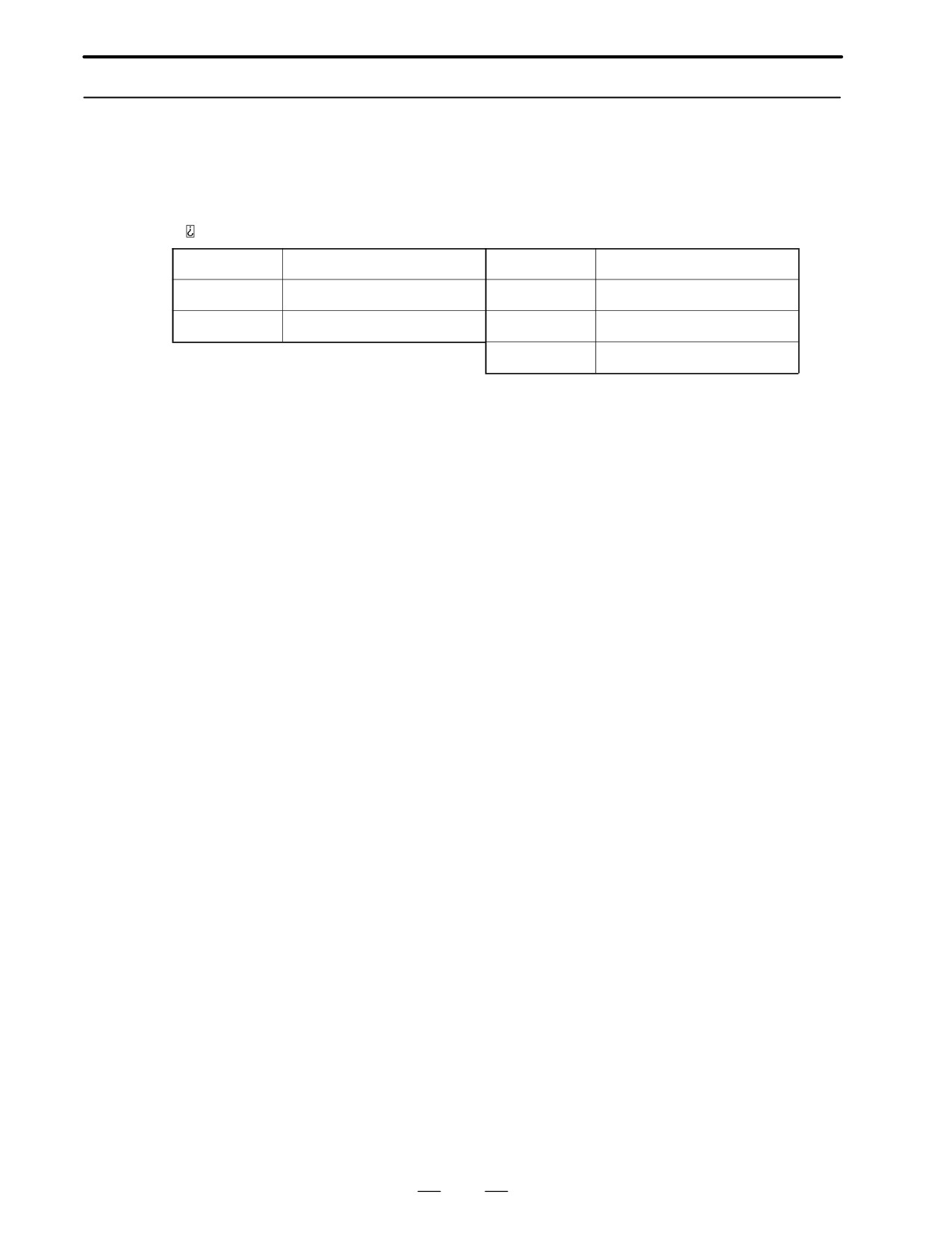
Motor specification number
α0.5/3000
A06B-0113-Bxxx
αC3/2000
A06B-0121-Bxxx
α1/3000
A06B-0371-Bxxx
αC6/2000
A06B-0126-Bxxx
α2/2000
A06B-0372-Bxxx
αC12/2000
A06B-0141-Bxxx
α2/3000
A06B-0373-Bxxx
αC22/1500
A06B-0145-Bxxx
α3/3000
A06B-0123-Bxxx
α M series
α6/2000
A06B-0127-Bxxx
Model name
Motor specification number
α6/3000
A06B-0128-Bxxx
αM3/3000
A06B-0161-Bxxx
α12/2000
A06B-0142-Bxxx
αM6/3000
A06B-0162-Bxxx
α12/3000
A06B-0143-Bxxx
αM9/3000
A06B-0163-Bxxx
α22/1500
A06B-0146-Bxxx
α L series
α22/2000
A06B-0147-Bxxx
Model name
Motor specification number
α22/3000
A06B-0148-Bxxx
αL3/3000
A06B-0561-Bxxx
α30/1200
A06B-0151-Bxxx
αL6/3000
A06B-0562-Bxxx
α30/2000
A06B-0152-Bxxx
αL9/3000
A06B-0564-Bxxx
α30/3000
A06B-0153-Bxxx
αL25/3000
A06B-0571-Bxxx
α40/2000
A06B-0157-Bxxx
αL50/3000
A06B-0572-Bxxx
α40/2000
A06B-0158-Bxxx
Motor with fan
α65/2000
A06B-0331-Bxxx
α100/2000
A06B-0332-Bxxx
α150/2000
A06B-0333-Bxxx
49
5. CONDITIONS FOR APPROVAL
RELATED TO THE IEC34
STANDARD
DESCRIPTIONS FOR THE α series
B-65142E/02
5.1.2
From the FANUC α (HV) series AC servo motors listed below, select the
motors that meet any combination in III.2
“Motor Types and
400 VAC Input Types
Specifications” (described later). The selected motors will meet the
IEC34 standard if they are used under the conditions described in this
chapter.
(HV) series
Model name
Motor specification number
Model name
Motor specification number
α3/3000HV
A06B-0171-Bxxx
α12/3000HV
A06B-0176-Bxxx
α6/3000HV
A06B-0172-Bxxx
α22/3000HV
A06B-0177-Bxxx
α30/3000HV
A06B-0178-Bxxx
50
5. CONDITIONS FOR APPROVAL
RELATED TO THE IEC34
B-65142E/02
DESCRIPTIONS FOR THE α series
STANDARD
5.2
DRIVES
5.2.1
The FANUC α , αC, αM, and αL series AC servo motors can be driven
only by the FANUC control motor amplifiers for 200 to 230 VAC.
200 VAC Input Types
5.2.2
The FANUC α (HV) series AC servo motors can be driven only by the
FANUC control motor amplifiers for 400 to 460 VAC.
400 VAC Input Types
51
5. CONDITIONS FOR APPROVAL
RELATED TO THE IEC34
STANDARD
DESCRIPTIONS FOR THE α series
B-65142E/02
5.3
POWER CABLE
CONNECTORS
The connector kit or cable assembly specified below must be used to
5.3.1
connect a power cable to the model α 0.5. This connector is not
Model A 0.5
waterproof.
D Connector kit
Housing: 3-178129-6 [AMP Japan specification]
A06B-6050-K119 [FANUC specification]
(This specification includes the contacts.)
Contact: 1-175217-2 [AMP Japan specification]
- The contacts of the α 0.5 connector are one-piece crimp type. The
size of the applicable wire is AWG#20, and the outside diameter of
the insulation is 1.7 to 2.6 mm.
The following dedicated tools are required to mount and remove the
contacts. They should be prepared separately from the connector kit.
Crimping tool specification:
914595-3 [AMP Japan]
A97L-0200-0979 M [FANUC]
Extractor specification:
914677-1 [AMP Japan]
A97L-0200-0980/D3 [FANUC]
The following FANUC power cables use the wires that meet the VDE.
D Cable assembly (14 m as standard)
Model with no brake:
A06B-6050-K822 [FANUC specification]
Model with a built-in brake:
A06B-6050-K823 [FANUC specification]
5.3.2
Section 8.2.3 of IEC204-1 (EN60204-1), which must be met to acquire
CE marking approval, stipulates that all exposed live conductors of
Models A1 and A2
electric equipment and machines be connected to a protection link circuit.
If the connector portion of a motor is exposed to the outside, its metal
portion should be covered with a non-moving insulation, or the metal
shell should be connected to a protection link circuit using the following
connector kit.
D Connector kit: A06B-6050-K121 [FANUC specification]
- The contacts of the α1 and α2 connectors are one-piece crimp type.
The sizes of the applicable wires are AWG#18 and AWG#16
respectively, and the outside diameters of the insulations are 1.8 to
2.8 mm (for #18) and 2.2 to 2.8 mm (for #16).
The following dedicated tools are required to insert and remove the
contacts. They should be prepared separately from the connector kit.
Crimping tool specification:
914596-3 (AMP Japan)
A97L-0200-0979/L [FANUC]
Extractor specification:
914677-1 (AMP Japan)
A97L-0200-0980/D3 [FANUC]
52
5. CONDITIONS FOR APPROVAL
RELATED TO THE IEC34
B-65142E/02
DESCRIPTIONS FOR THE α series
STANDARD
- Cables with an external size of 9.9 to 10.9 mm2 should be used to
provide a sufficient waterproof performance related to cable
clamps.
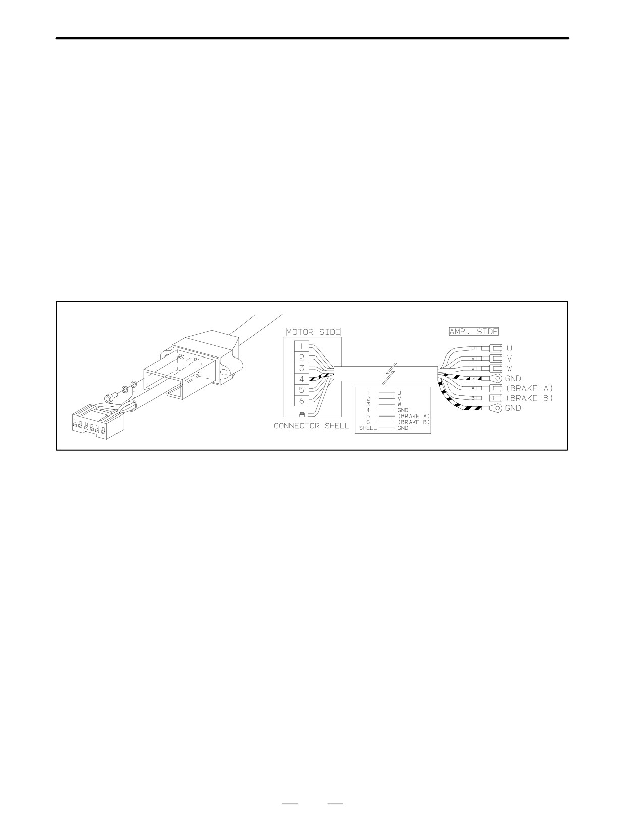
The number of cable conductors is 1 greater than the conventional
U/V/W/G/(B1)/(B2) to provide for the connector shell protection
link circuit, that is 5 or 7 conductors.
The following FANUC power cables use the wires that meet the VDE.
D Cable assembly (14 m as standard)
Model with no brake: A06B-6050-K824 [FANUC specification]
Model with a built-in brake:
A06B-6050-K825 [FANUC specification]
- The motor grounding wire (at terminal 4) and connector shell
grounding wire should be bundled with one crimping terminal and
connected to the grounding terminal of the amplifier. The
grounding lines must be indicated in yellow/green.
53
5. CONDITIONS FOR APPROVAL
RELATED TO THE IEC34
STANDARD
DESCRIPTIONS FOR THE α series
B-65142E/02
5.3.3
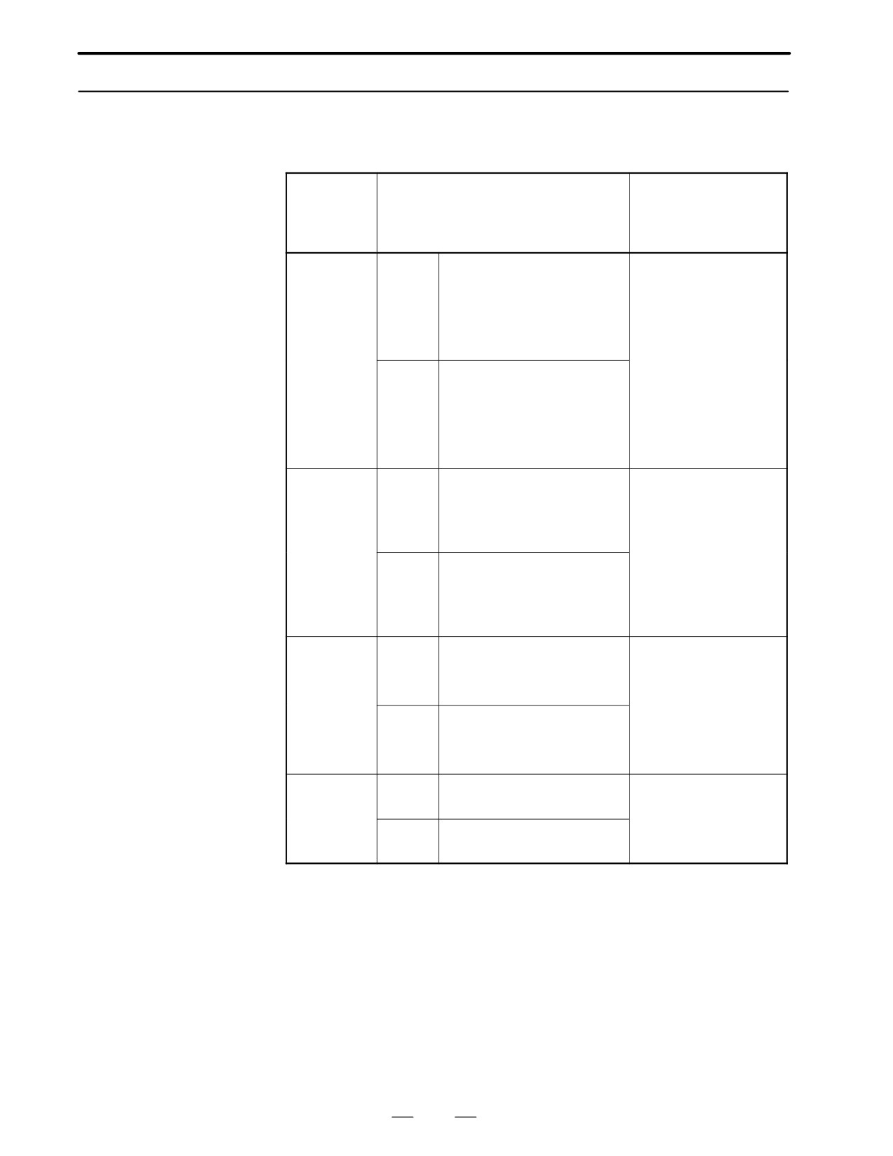
The motor power cable and brake fan unit must be connected using the
connectors and cable clamps specified below.
Models A3 and Higher
Motor
Plug connector maker
Cable clamp
model
specification
specification
name
[FANUC specification]
and connector
maker name
α3/3000,
Straight
H/MS3106A18-10S-D-T (10)
H/MS3057-10A (10)
α6/2000,
type
[A63L-0001-0648/61810SH]
[A63L-0001-0592/10AK]
α6/3000,
α3/3000HV,
Hirose Electric
α6/3000HV,
αC3/2000,
αC6/2000,
αM3/ 3000,
L-shape
H/MS3108B18-10S-D-T (10)
αM6/3000,
type
[A63L-0001-0648/81810SH]
αM9/3000
αL3/3000,
αL6/ 3000,
αL9/3000
α12/2000,
Straight
JL04V-6A22-22SE-EB
JL04-2022CK-(14)
α12/3000,
type
[A63L-0001-0648/62222SJ]
[A63L-0001-0653/12A]
α12/3000HV,
Japan Aviation
α22/3000HV,
Electronics Industry
α30/3000HV,
α22/1500,
L-shape
JL04V-8A22-22SE-EB
α22/2000,
type
[A63L-0001-0648/82222SJ]
α30/1200,
αC12/2000,
αC22/1500
α22/3000,
Straight
JL04V-6A24-10SE (G)-EB
JL04-2428CK-(17)
α30/2000,
type
[A63L-0001-0648/62410SJ]
[A63L-0001-0653/16A]
α30/3000,
Japan Aviation
α40/2000,
Electronics Industry
α40/2000
L-shape
JL04V-8A24-10SE (G)-EB
(with fan)
type
[A63L-0001-0648/82410SJ]
αL25/3000,
αL50/2000
Brake and
Straight
JL04V-6A10SL-3SE-EB
JL04-1012CK-(05)
fan unit
type
[A63L-0001-0648/610SL3SJ]
[A63L-0001-0653/04A]
connection
L-shape
JL04V-8A10SL-3SE-EB
Japan Aviation
Electronics Industry
type
[A63L-0001-0648/810SL3SJ]
A Also see Section 8.
A The power cable for the α22/3000, α30/2000, α30/3000, α40/2000,
αL25/3000, and αL50/2000 has 7 conductors. Its grounding wire (one
conductor) must have a cross section not less than that for the U, V, or
W line (two conductors). For the grounding wire for the other
connectors, its cross section must not be less than that for the U, V, or
W line.
A If a cable or conduit hose seal adapter is used, consult an appropriate
connector maker.
54
5. CONDITIONS FOR APPROVAL
RELATED TO THE IEC34
B-65142E/02
DESCRIPTIONS FOR THE α series
STANDARD
The following specifications are approved for the IEC34 standard.
5.4
APPROVED
SPECIFICATIONS
5.4.1
The allowable maximum speeds of motors are as listed below.
Motor Speed (IEC34-1)
Motor model
Rated-output
Allowable maximum
speed [1/min]
speed [1/min]
α1/3000,
α2/3000,
3000
3000
α3/3000,
α6/3000,
α12/3000,
α22/3000,
α30/3000,
α3/3000HV,
α6/3000HV,
α12/3000HV,
α22/3000HV,
α30/3000HV
αM3/3000,
αM6/3000,
αM9/3000,
αL3/3000,
αL6/3000,
αL9/3000
αL25/3000
α2/2000,
α6/2000,
2000
2500
α12/2000,
α22/2000,
α30/2000,
α40/2000,
αC3/2000,
αC6/2000,
αC12/2000,
αL50/2000
α22/1500,
αC22/1500
1500
2000
α30/1200
1200
1500
α65/2000,
α100/2000,
α150/2000
2000
2000
Motors must not be used at a speed higher than the allowable maximum
speed. Motors cannot be used continuously at the allowable maximum
speed. The output is not specified for the allowable maximum speed. The
allowable maximum speed applies only to motors. Separate limits are
laid on the drive units.
The rated output is guaranteed as continuous output only for the
5.4.2
rated-output speed. At a speed other than the rate-output speed, the
Output (IEC34-1)
output is specified in terms of a continuous operation torque. The output
in an intermittent operation range is not specified. The approved output
of each model is as listed in II to VI.3,
“Specifications and
Characteristics” (described later) for the α, α(HV), αC, αM, and αL
series.
5.4.3
The protection types are as listed below.
Protection Type
Motor model
IP
Approval conditions
(IEC34-5)
α0.5/3000
55
Applies only to the motor section;
for connectors, IP00 applies.
α65/2000, α100/2000,
55
Only when a conduit meeting
α150/2000
IP55 is used.
Models other than those listed
55
Only when a specified connector
above.
is used.
55
5. CONDITIONS FOR APPROVAL
RELATED TO THE IEC34
STANDARD
DESCRIPTIONS FOR THE α series
B-65142E/02
IP5x: Dustproof machines
A dust-proof machine shall be protected from dust to an extent that
dust does not impede the normal operation of the motor if the motor
is not protected from dust completely.
IPx5: Sprinkle-proof machines
A sprinkle-proof machine shall not suffer inadvertent influence when
they are exposed to water sprinkled from nozzles at any angle to the
machine.
The conditions of the IPx5 type test are as follows:
Nozzle inside diameter:
6.3 mm
Amount of sprinkled water:
12.5 liters/minute
Water pressure at the nozzle:
30 kPa
Sprinkle time per a surface of 1 m2:
1 minute
Minimum required time:
3 minutes
Distance between the nozzle and machine: Approximately 3 m
Note
IPx5 evaluates machines for waterproofness in a
short-term test as described above, allowing chances that
the machines may get dry after the test. If a machine is
exposed to liquids other than water or so continuously to
water that it cannot get dry, it may suffer inadvertent
influence even if the degree of exposure is low.
The motor cooling methods are as listed below.
5.4.4
Cooling Method
Motor model
IC code
Method
(ICE34-6)
α40/2000 with fan
IC 416
Fully closed; cooled by an external in-
dependent fan
Other models
IC 410
Fully closed; cooled by a natural air flow
5.4.5
The motors can be mounted by the following methods.
Mounting Method
IMB5: Flange mounting with the shaft facing sideways (from the rear)
(IEC34-7)
IMV1: Flange mounting with the shaft facing upward (from the rear)
IMV3: Flange mounting with the shaft facing downward (from the rear)
The heat protection type is as listed below:
5.4.6
T P 2 1 1
Heat Protection
1: Temperature rise limit category 1 for heat protection
(IEC34-11)
1: Stop only at stage 1 (no warning)
2: Protection for gradual and abrupt overload
56