FANUC a Series AC SERVO MOTOR. Description Manual (GFZ-65142E/02) - page 1
B-65142E/02
PREFACE
PREFACE
This manual describes the specifications and characteristics of the A series
servo motors. The manual consists of the following chapters:
I. SPECIFICATIONS FOR THE α series
This chapter provides general notes on the use of the A series and
explains how to select the optimum motor for a given application.
This chapter also provides the specifications common to each model
of the α series, concerning the detectors, internal brakes, plug
connectors, and so forth.
II. FANUC AC SERVO MOTOR α series
This chapter explains how to specify a certain A series servo motor and
provides specifications, dimensions, and data sheets for the entire
range of α series servo motors.
III. FANUC AC SERVO MOTOR A (HV) series
This chapter explains how to specify a certain A(HV) series servo
motor and provides specifications, dimensions, and data sheets for the
entire range of α(HV) series servo motors.
IV. FANUC AC SERVO MOTOR αC series
This chapter explains how to specify a certain AC series servo motor
and provides specifications, dimensions, and data sheets for the entire
range of αC series servo motors.
V. FANUC AC SERVO MOTOR αM series
This chapter explains how to specify a certain αM series servo motor
and provides specifications, dimensions, and data sheets for the entire
range of αM series servo motors.
VI. FANUC AC SERVO MOTOR αL series
This chapter explains how to specify a certain αL series servo motor
and provides specifications, dimensions, and data sheets for the entire
range of αL series servo motors.
Although this manual provides information on detector signal outputs, it
does not describe connection to a servo amplifier or NC. For details of
these connections, refer to the ”FANUC CONTROL MOTOR α series
Maintenance Manual” (B-65165E).
PREFACE
B-65142E/02
Related manuals
The following six kinds of manuals are available for FANUC CONTROL
MOTOR α series. In the table, this manual is marked with an asterisk (*).
Document
Document name
Major contents
Major usage
number
A Specification
FANUC AC SERVO MOTOR α series
A Characteristics
B-65142E
*
DESCRIPTIONS
A External dimensions
A Connections
A Selection of motor
A Connection of motor
A Specification
FANUC AC SPINDLE MOTOR α series
A Characteristics
B-65152E
DESCRIPTIONS
A External dimensions
A Connections
A Specifications and
functions
A Selection of
FANUC CONTROL MOTOR AMPLIFIER
A Installation
amplifier
B-65162E
α series DESCRIPTIONS
A External dimensions and
A Connection of
maintenance area
amplifier
A Connections
A Start up the system
A Start up procedure
(Hardware)
FANUC CONTROL MOTOR α series
B-65165E
A Troubleshooting
A Troubleshooting
MAINTENANCE MANUAL
A Maintenance of motor
A Maintenance of
motor
A Initial setting
FANUC AC SERVO MOTOR α series
B-65150E
A Setting parameters
PARAMETER MANUAL
A Start up the system
A Description of parameters
(Software)
A Tuning the system
A Initial setting
FANUC AC SPINDLE MOTOR α series
(Parameters)
B-65160E
A Setting parameters
PARAMETER MANUAL
A Description of parameters
B-65142E/02
Table of Contents
PREFACE
I. DESCRIPTIONS FOR THE A series
1. GENERAL .
3
2. PRECAUTIONS ON USE .
4
2.1
APPLICABLE AMPLIFIERS
5
2.2
INSTALLATION
8
2.3
COUPLING
9
2.4
AXIS LOAD
11
2.5
ENVIRONMENT
12
2.6
ACCEPTANCE AND STORAGE
15
3. INSTRUCTIONS .
16
3.1
DRIVE SHAFT COUPLING
17
3.2
MACHINE MOVEMENT PER 1 REVOLUTION OF MOTOR SHAFT
20
4. SELECTING A MOTOR .
21
4.1
CALCULATING CONDITIONS FOR SELECTING A MOTOR
22
4.1.1
Calculating the Load Torque and Load Inertia
23
4.1.2
Calculating the Acceleration Torque
27
4.1.3
Calculating the Root-mean-square Value of the Torques
30
4.1.4
Calculating the Percentage Duty Cycle with the Maximum Cutting Torque
31
4.2
PRECAUTIONS FOR USING LINEAR SCALE
33
4.3
MOTOR SELECTION
35
4.3.1
Blanks for Those Other than Data
35
4.3.2
Data
35
4.4
CHARACTERISTIC CURVE AND DATA SHEET
45
4.4.1
Performance Curves
45
4.4.2
Data Sheet
45
4.4.3
How to Use Duty Cycle Curves
47
5. CONDITIONS FOR APPROVAL RELATED TO THE IEC34 STANDARD
48
5.1
APPLICABLE MOTORS
49
5.1.1
200 VAC Input Types
49
5.1.2
400 VAC Input Types
50
5.2
DRIVES
51
5.2.1
200 VAC Input Types
51
5.2.2
400 VAC Input Types
51
5.3
POWER CABLE CONNECTORS
52
5.3.1
Model α 0.5
52
5.3.2
Models α1 and α2
52
5.3.3
Models α3 and Higher
54
c-1
TABLE OF CONTENTS
B–65142E/02
5.4
APPROVED SPECIFICATIONS
55
5.4.1
Motor Speed (IEC34-1)
55
5.4.2
Output (IEC34-1)
55
5.4.3
Protection Type (IEC34-5)
55
5.4.4
Cooling Method (ICE-34-6)
56
5.4.5
Mounting Method (IEC34-7)
56
5.4.6
Heat Protection (IEC34-11)
56
6. FEEDBACK DETECTOR .
57
6.1
BUILT-IN DETECTOR
58
6.2
PULSE CODER RESOLUTION AND CONTROL RESOLUTION
59
6.3
ABSOLUTE-TYPE PULSE CODER
60
6.4
SEPARATE TYPE POSITION DETECTOR
61
6.5
DETECTOR INPUT/OUTPUT SIGNALS
64
6.6
SIGNALS INPUT/OUTPUT FROM SEPARATE-TYPE DETECTOR
65
7. BUILT-IN BRAKE .
66
7.1
BRAKE SPECIFICATIONS
67
7.2
CONNECTION OF THE BRAKES
69
8. CONNECTORS .
71
8.1
CONNECTOR ON THE MOTOR SIDE
72
8.1.1
Specifications of Connectors on the Motor Side
72
8.2
CONNECTORS ON THE CABLE SIDE (MODELS α0.5, α1 and α2)
74
8.2.1
Connector Kit Specifications
74
8.2.2
Cable Assembly Specifications (14m standard)
75
8.3
SPECIFICATIONS OF THE CONNECTORS ON THE CABLE SIDE
(MODELS α3 AND HIGHER)
76
8.3.1
Specifications of Plug Connectors on the Cable Side (Waterproof TÜV-Approved Type)
78
8.3.2
Specifications of Plug Connectors on the Cable Side (Waterproof Type)
79
8.3.3
Specifications of Plug Connectors on the Cable Side (Non-waterproof Type)
80
9. COOLING FAN FOR MODEL A40 .
81
II. FANUC AC SERVO MOTOR A series
1. GENERAl .
85
1.1
FEATURES OF COMPACT-TYPE α SERVO MOTOR (α0.5)
86
1.2
FEATURES OF SERVO MOTOR α SERIES (α1 TO α150)
87
2. TYPES OF MOTORS AND DESIGNATION .
88
3. SPECIFICATIONS AND CHARACTERISTICS .
91
3.1
TYPE OF MOTORS AND SPECIFICATIONS
92
3.2
CHARACTERISTIC CURVE AND DATA SHEET
96
3.3
OUTLINE DRAWINGS
109
3.4
CONNECTION OF POWER LINE
126
c-2
B-65142E/02
TABLE OF CONTENTS
III. FANUC AC SERVO MOTOR a(HV) series
1. GENERAL .
131
2. TYPES OF MOTORS AND DESIGNATION .
132
3. SPECIFICATIONS AND CHARACTERISTICS .
133
3.1
TYPES OF MOTORS AND SPECIFICATIONS
134
3.2
CHARACTERISTIC CURVE AND DATA SHEET
136
3.3
OUTLINE DRAWINGS
142
3.4
CONNECTION OF POWER LINE
149
IV. FANUC AC SERVO MOTOR aC series
1. GENERAl .
153
2. TYPES OF MOTORS AND DESIGNATION .
154
3. SPECIFICATIONS AND CHARACTERISTICS .
155
3.1
TYPES OF MOTORS AND SPECIFICATIONS
156
3.2
CHARACTERISTIC CURVE AND DATA SHEET
157
3.3
OUTLINE DRAWINGS
162
3.4
CONNECTION OF POWER LINE
169
V. FANUC AC SERVO MOTOR aM series
1. GENERAl .
173
2. TYPES OF MOTORS AND DESIGNATION .
174
3. SPECIFICATIONS AND CHARACTERISTICS .
175
3.1
TYPES OF MOTORS AND SPECIFICATIONS
176
3.2
CHARACTERISTIC CURVE AND DATA SHEET
177
3.3
OUTLINE DRAWINGS
181
3.4
CONNECTION OF POWER LINE
186
VI. FANUC AC SERVO MOTORg L series
1. GENERAl .
189
2. TYPES OF MOTORS AND DESIGNATION .
190
3. SPECIFICATIONS AND CHARACTERISTICS .
191
3.1
TYPES OF MOTORS AND SPECIFICATIONS
192
3.2
CHARACTERISTIC CURVE AND DATA SHEET
193
3.3
OUTLINE DRAWINGS
199
3.4
CONNECTION OF POWER LINE
204
c-3
I. DESCRIPTIONS FOR THE α series
B-65142E/02
DESCRIPTIONS FOR THE α series
1. GENERAL
GENERAL
1
The FANUC AC servo motor α series has been designed for machine tool
feed axis applications. This servo motor α series has the following
features:
Smooth rotation
The special magnetic pole shape minimizes torque ripples which, when
combined with precise current control and accurate pulse coder feedback,
enables extremely smooth motor rotation.
Excellent acceleration
The use of a special rotor shape results in motors that are smaller and
lighter than previous models, but which can develop a high level of
torque.
These motors, therefore, provide excellent acceleration
characteristics.
High reliability
A totally-enclosed, friction-free brushless design is used. This allows
the servo motors to be used in demanding environments with no need for
special checks or maintenance.
Built-in, high-precision
A low-indexing-error optical encoder (pulse coder) is built into the
detector
motors. This pulse coder enables precise positioning.
Pulse coders that output 8,192, 65,536, or 1,000,000 pulses per rotation
are available. As such, the α series motors can be used for positioning
applications ranging from simple positioning to those requiring a high
degree of precision.
(Available pulse coders vary with the series and
model of the motor being used.)
The FANUC AC servo motor α series consists of the α , αC, αM, and
α(HV) series, all of which are suitable general machine tool, control
applications, and the αL series, designed for controlling machine tools
that require frequent positioning operations, such as punch presses and
PCB drilling machines.
Each of these series is further divided into the following models:
A α series
α0.5/3000, α1/3000, α2/2000, α2/3000, α3/3000, α6/2000,
α6/3000, α12/2000, α12/3000, α22/1500, α22/2000, α22/3000,
α30/1200, α30/2000, α30/3000, α40/2000, α40/2000 (with fan),
α65/2000, α100/2000, α150/2000
A α(HV) series
α3/3000HV, α6/3000HV, α12/3000HV, α22/3000HV, A30/3000HV
A αC series
αC3/2000, αC6/2000, αC12/2000, αC22/1500
A αM series
αM3/3000, αM6/3000, αM9/3000
A αL series
αL3/3000, αL6/3000, αL9/3000, αL25/3000, αL50/2000
3
B-65142E/02
DESCRIPTIONS FOR THE α series
2. PRECAUTIONS ON USE
The FANUC A series AC servo motors can be driven using FANUC α
2.1
series controller amplifiers.
APPLICABLE
AMPLIFIERS
Servo amplifier module (SVM)/
Servo amplifier unit (SVU)
Motor
model
Model name
Specification
Connection
axis
A0.5/3000
SVM1-12
A06-6079-H101
A1/3000
A2/2000
SVM2-12/12
A06B-6079-H201
L and M axes
A2/3000
SVM2-12/20
A06B-6079-H202
L axis
SVM2-12/40
A06B-6079-H204
L axis
SVM3-12/12/12
A06B-6079-H301
L, M and N
A06B-6080-H301 (Note 3)
axes
SVM3-12/12/20
A06B-6079-H302
L and M axes
A06B-6080-H302 (Note 3)
SVM3-12/20/20
A06B-6079-H303
L axis
A06B-6080-H303 (Note 3)
SVM3-12/12/40
A06B-6079-H305
L and M axes
A06B-6080-H305 (Note 3)
SVM3-12/20/40
A06B-6079-H306
L axis
A06B-6080-H306 (Note 3)
SVU1-12
A06B-6089-H101
SVU2-12/12
A06B-6089-H201
L and M axes
SVU2-12/20
A06B-6089-H202
L axis
SVU2-12/40
A06B-6089-H204
L axis
AC3/2000
SVM1-20
A06B-6079-H102
AC6/2000
AC12/2000
SVM2-12/20
A06B-6079-H202
M axis
SVM2-20/20
A06B-6079-H203
L and M axes
SVM2-20/40
A06B-6079-H205
L axis
SVM3-12/12/20
A06B-6079-H302
N axis
A06B-6080-H302 (Note 3)
SVM3-12/20/20
A06B-6079-H303
M and N axes
A06B-6080-H303 (Note 3)
SVM3-20/20/20
A06B-6079-H304
L, M and N
A06B-6080-H304 (Note 3)
axes
SVM3-12/20/40
A06B-6079-H306
M axis
A06B-6080-H306 (Note 3)
SVM3-20/20/40
A06B-6079-H307
L and M axes
A06B-6080-H307 (Note 3)
SVU1-20
A06B-6089-H102
SVU2-12/20
A06B-6089-H202
M axis
SVU2-20/20
A06B-6089-H203
L and M axes
SVU2-20/40
A06B-6089-H205
L axis
5
2. PRECAUTIONS ON USE
DESCRIPTIONS FOR THE α series
B-65142E/02
Servo amplifier module (SVM)/
Servo amplifier unit (SVU)
Motor
model
Model name
Specification
Connection
axis
A3/3000
SVM1-40S
A06B-6079-H103
A6/2000
SVM1-40L
A06B-6079-H104
AM3/3000
AL3/3000
SVM2-12/40
A06B-6079-H204
M axis
SVM2-20/40
A06B-6079-H205
M axis
SVM2-40/40
A06B-6079-H206
L and M axes
SVM2-40/80
A06B-6079-H207
L axis
SVM2-40L/40L
A06B-6079-H209
L and M axes
SVM3-12/12/40
A06B-6079-H305
N axis
A06B-6080-H305 (Note 3)
SVM3-12/20/40
A06B-6079-H306
N axis
A06B-6080-H306 (Note 3)
SVM3-20/20/40
A06B-6079-H307
N axis
A06B-6080-H307 (Note 3)
SVU1-40
A06B-6089-H104
SVU2-12/40
A06B-6089-H204
M axis
SVU2-20/40
A06B-6089-H205
M axis
SVU2-40/40
A06B-6089-H206
L and M axes
SVU2-40/80
A06B-6089-H207
L axis
A12/2000
SVM1-40L
A06B-6079-H104
AC22/1500
SVM2-12/40
A06B-6079-H204
M axis
(The SVU2
SVM2-20/40
A06B-6079-H205
M axis
is unappli-
SVM2-40/40
A06B-6079-H206
L and M axes
cable to
SVM2-40/80
A06B-6079-H207
L axis
the AC22/
SVM2-40L/40L
A06B-6079-H209
L and M axes
1500.)
SVM3-12/12/40
A06B-6079-H305
N axis
A06B-6080-H305 (Note 3)
SVM3-12/20/40
A06B-6079-H306
N axis
A06B-6080-H306 (Note 3)
SVM3-20/20/40
A06B-6079-H307
N axis
A06B-6080-H307 (Note 3)
SVU1-40
A06B-6089-H104
SVU2-12/40
A06B-6089-H204
M axis
SVU2-20/40
A06B-6089-H205
M axis
SVU2-40/40
A06B-6089-H206
L and M axes
SVU2-40/80
A06B-6089-H207
L axis
A22/1500
SVM1-40L
A06B-6079-H104
SVM2-40/80
A06B-6079-H207
L axis
SVM2-40L/40L
A06B-6079-H209
L and M axes
SVU1-40
A06B-6089-H104
6
B-65142E/02
DESCRIPTIONS FOR THE α series
2. PRECAUTIONS ON USE
Servo amplifier module (SVM)/
Servo amplifier unit (SVU)
Motor
model
Model name
Specification
Connection
axis
A6/3000
SVM1-80
A06B-6079-H105
AM6/3000
AL6/3000
SVM2-40/80
A06B-6079-H207
M axis
SVM2-80/80
A06B-6079-H208
L and M axes
SVU1-40
A06B-6089-H104
SVU2-40/80
A06B-6089-H207
M axis
SVU2-80/80
A06B-6089-H208
L and M axes
SVU2-12/80
A06B-6089-H209
M axis
SVU2-20/80
A06B-6089-H210
M axis
A12/3000
SVM1-80
A06B-6079-H105
A22/2000
A30/1200
SVM2-40/80
A06B-6079-H207
M axis
AM9/3000
SVM2-80/80
A06B-6079-H208
L and M axes
AL9/3000
SVU1-80
A06B-6089-H105
A30/2000
SVM1-130
A06B-6079-H106
A40/2000
SVU1-130
A06B-6089-H106
A22/3000
SVM1-130
A06B-6079-H106 (Note 4)
A30/3000
A40/2000
(with FAN)
SVU1-130
A06B-6089-H106 (Note 4)
AL25/3000
AL50/2000
Notes
1. If a motor is used in a combination other than those listed
above, it will be broken, except for the C series servo
amplifier. Contact FANUC for more information.
2. For details of the α series control motor amplifiers, refer to
“FANUC Control Motor Amplifier A series Descriptions”
(B-65162E).
3. The specification of the A series servo amplifier modules for
three axes (SVM3) varies from one NC to another. Refer to
“FANUC Control Motor Amplifier A series Descriptions”
(B-65162E).
4. When the SVM-130 is used to drive the A22/3000,
A30/3000, A40/2000 (with fan), AL25/3000, or AL50/2000,
it must be cooled by a forced air flow. For details, refer to
“FANUC Control Motor Amplifier A series Descriptions”
(B-65162E).
7
2. PRECAUTIONS ON USE
DESCRIPTIONS FOR THE α series
B-65142E/02
2.2
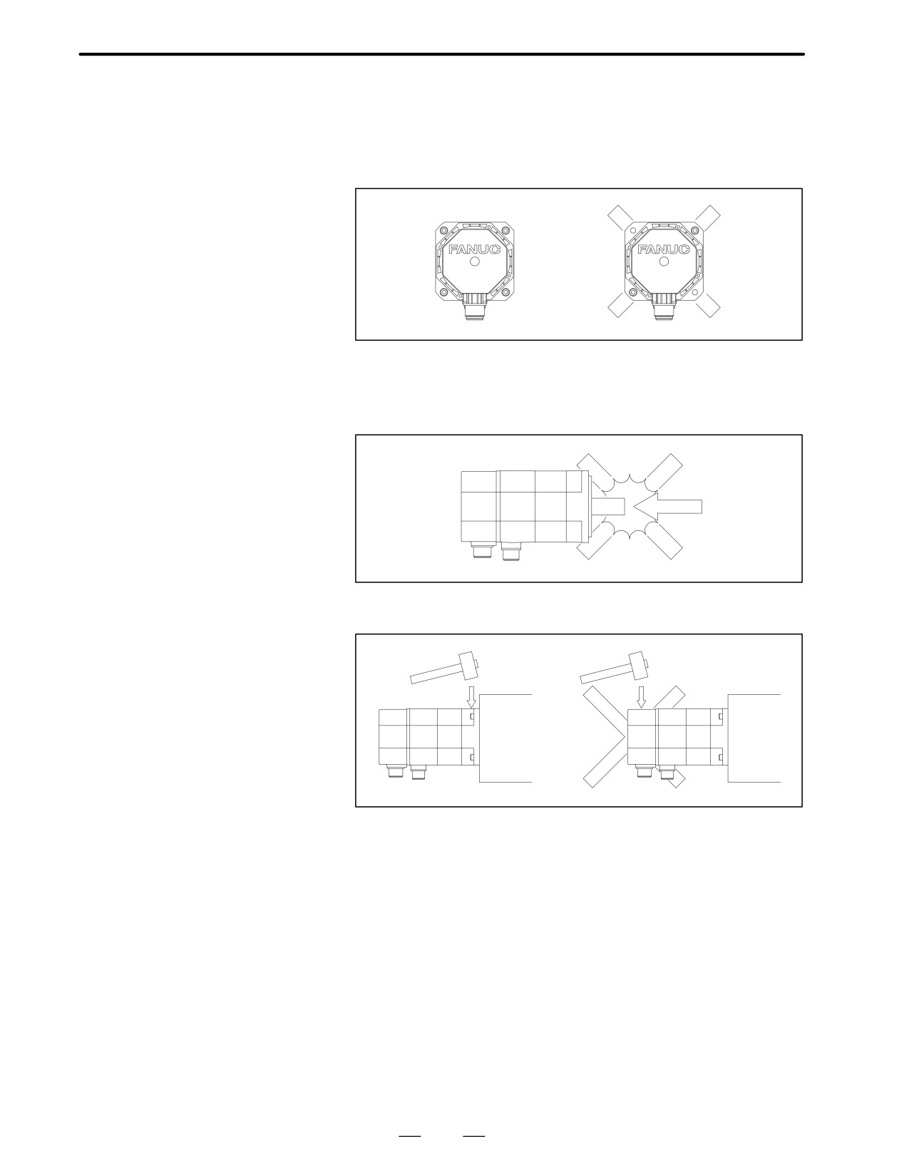
A The servo motor contains a precision detector, and is carefully
INSTALLATION
machined and assembled to provide the required precision. Pay
attention to the following items to maintain the precision and prevent
damage to the detector.
A Secure the servo motor uniformly using four bolt holes provided on
the front flange.
A When mounting on the machine, take care not to apply a shock to the
motor.
A When it is unavoidable to tap the motor for adjusting the position, etc.,
use a plastic hammer and tap only the front flange if possible.
8
B-65142E/02
DESCRIPTIONS FOR THE α series
2. PRECAUTIONS ON USE
A precision detector is directly connected to the servo motor shaft.
2.3
Pay attention to the following items to prevent damage to the detector.
COUPLING
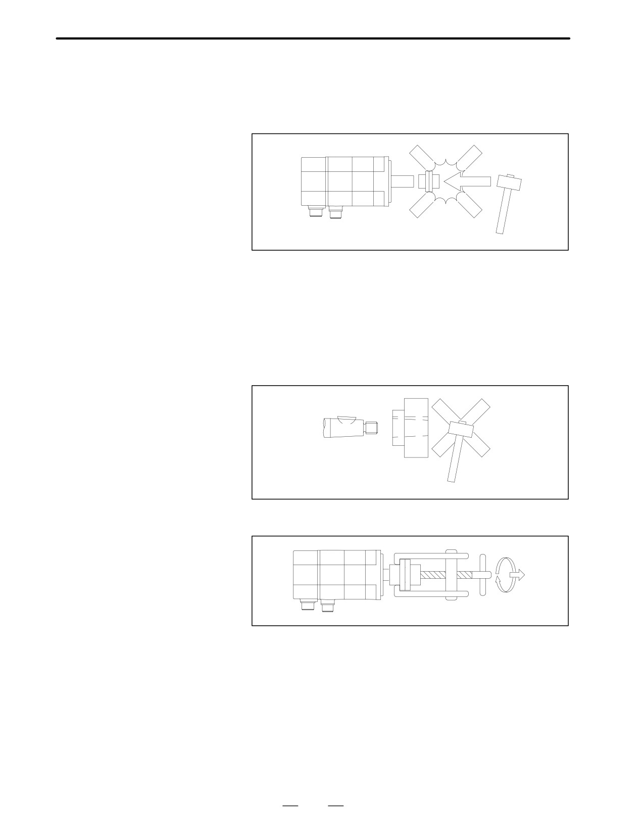
A When connecting the power transmission elements such as a gear, a
pulley and a coupling to the shaft, take care not to apply a shock to the
shaft.
A Generally, in the case of straight shaft, use a span ring for connection
with the shaft.
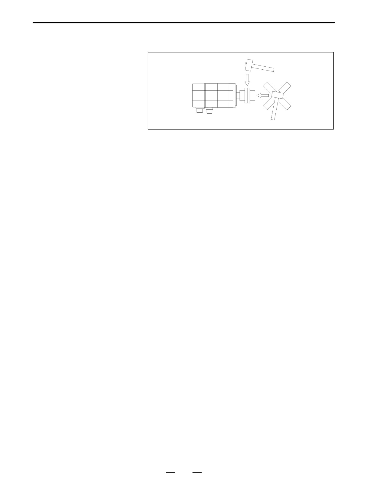
A In the case of tapered shaft, match the tapered surface with the power
transmission element and fix by tightening the screw at the end. When
the woodruff key is too tight, don’t tap it with a hammer. Use the
woodruff key mainly for positioning, and use the tapered surface for
torque transmission. Machine the tapered surface of the power
transmission element so that over 70% of the whole surface is
contacted.
A To remove the connected power transmission element, be sure to use
a jig such as a gear puller.
9
2. PRECAUTIONS ON USE
DESCRIPTIONS FOR THE α series
B-65142E/02
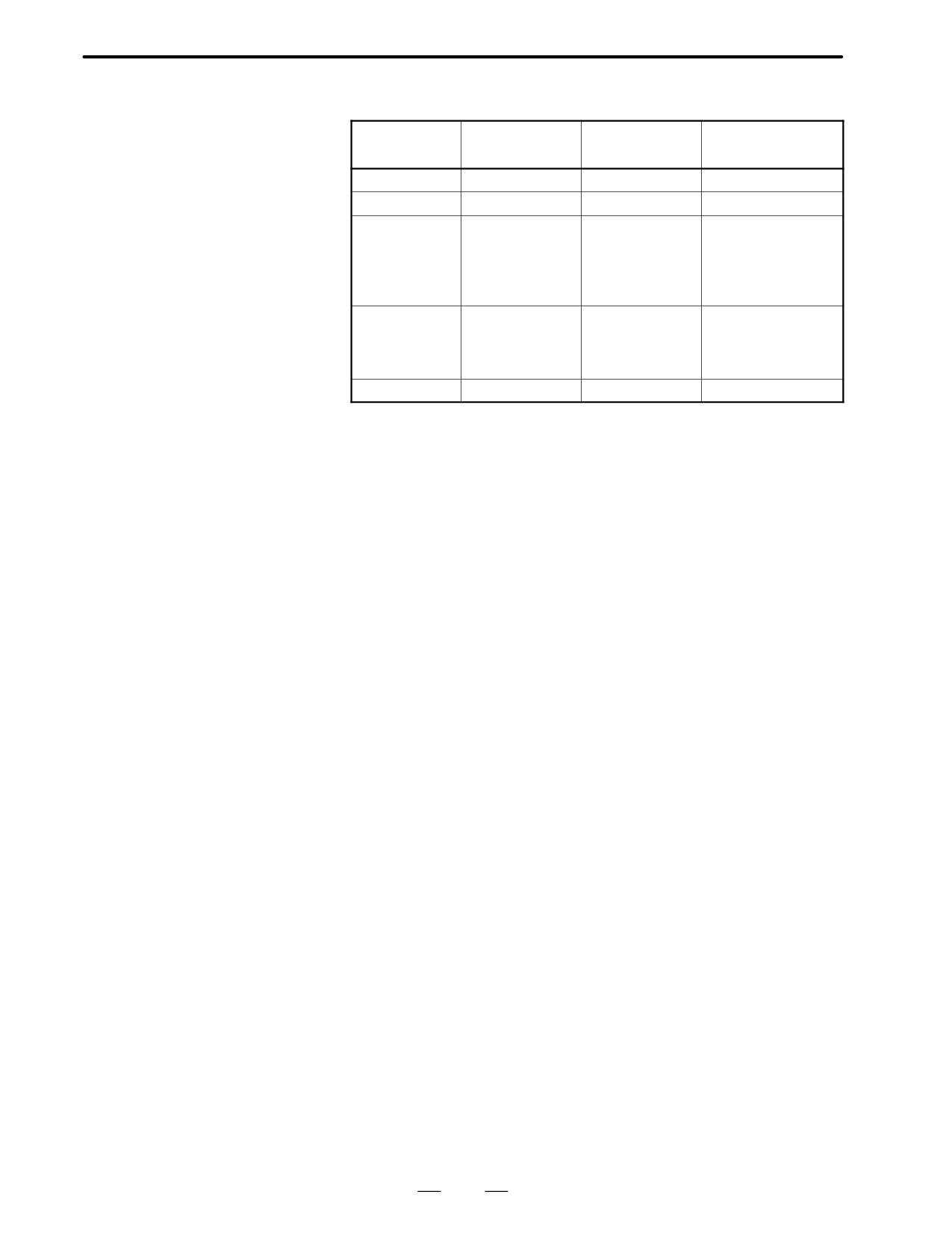
A When tapping slightly to remove the tightly contacted tapered surface,
tap in the radial direction to prevent a shock in the axial direction.
A Suppress the rotary unbalance of the connected power transmission
element to the level as low as possible. It is usually believed that there
is no problem in the symmetrical form . Be careful when rotating
continuously the asymmetrical different form power transmission
element. Even if the vibration caused by the unbalance is as small as
0.5G, it may damage the motor bearing or the detector.
An exclusive large oil seal is used in the front flange of the models
α3/6/12/22/30/40, α3/6/12/22/30HV, αC3/6/12/22, αM3/6/9, and
αL3/6/9.
The oil seal surface is made of steel plate. Take care not to apply a force
to the oil seal when installing the motor or connecting the power
transmission elements.
10
B-65142E/02
DESCRIPTIONS FOR THE α series
2. PRECAUTIONS ON USE
The allowable axis load of the motor shaft is as follows.
2.4
AXIS LOAD
Front bearing
Motor model
Radial load
Axial load
(reference)
α0.5
20kg
5kg
6902
α1/2
25kg
8kg
6003
α3/6
70kg
20kg
6205
α3/6HV
αC3/6
αM3/6/9
αL3/6/9
α12/22/30/40
450kg
135kg
6208
α12/22/30HV
αC12/22
αL25/50
α65/100/150
900kg
250kg
6312
The above values are the reference assuming the use as a feed axis on the
typical machine tool.
A
The allowable radial load is the value when a load is applied to the
shaft end. It indicates the total continuous force applied to the shaft
in some methods of mounting (e.g, belt tension) and the force by load
torque (e.g., moment/pulley radius).
A
The belt tension is critical particularly when a timing belt is used. Too
tight belt causes breakage of the shaft or other fault.
Belt tension must be controlled so as not to exceed the limits calculated
from the permissible radial load indicated above.
A
In some operation conditions, the pulley diameter and the gear size
need to be checked. For example, when using the model α3 with a
pulley/gear with the radius of 2.5cm or less, the radial load at the
occurrence of 180kg⋅cm torque will exceed 70kg. In the case of timing
belt, as the belt tension is added to this value, it is thus necessary to
support the shaft end.
The timing belt is also subject to the belt tension restrictions.
Therefore, some support is required; for example, the end of the motor
shaft should be supported mechanically.
A
Actually, when using a timing belt, a possible fault like a broken shaft
can be prevented by positioning the pulley as close to the bearing as
possible.
A
When there is a possibility of a large load, the machine tool builder
needs to examine the life by referring to the shaft diameter, bearing,
etc.
A
Since the standard single row deep groove ball bearing is used for the
motor bearing, a very large axial load can not be used. Particularly,
when using a worm gear and a helical gear, it is necessary to provide
another bearing.
A
The motor bearing is generally fixed with a C-snap ring, and there is
a small play in the axial direction. When this play influences the
positioning in the case of using a worm gear and a helical gear, for
example, it is necessary to fix it with another bearing.
11
2. PRECAUTIONS ON USE
DESCRIPTIONS FOR THE α series
B-65142E/02
2.5
ENVIRONMENT
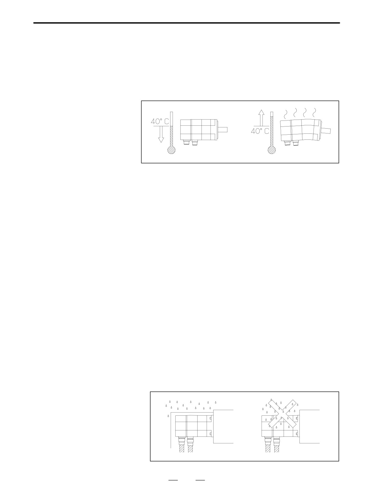
Ambient temperature
The ambient temperature should be 40°C or less. When operating the
machine at a higher temperature, it is necessary to lower the output power
so that the motor temperature does not exceed the specified constant
value.
(The values in the data sheet are determined for an ambient
temperature of 20°C.)
Vibration
When installed in a machine, the vibration applied to the motor must not
exceed 5G.
Installation height
Up to 1,000 meters above the sea level requires, no particular provision
for attitude. When operating the machine at a higher level, special care
is unnecessary if the ambient temperature is lowered 1°C at every 100m
higher than 1,000m. For example, when the machine is installed at a place
of 1,500 meters above sea level, there is no problem if the ambient
temperature is 35°C or less. For higher temperatures, it is necessary to
limit the output power.
If any one of the three environmental conditions specified above is not
satisfied, the output must be restricted.
Drip-proof environment
The protection form for a single motor unit satisfies IP55 of the IEC
standards (equivalent to JP55, dust-proof and jet-proof type, of JIS
C4004-1980, code for revolving electric machines)(except the
connectors of the α0.5).
(The α65 to α150 use the terminal box
specification, thus IP54 applies to these motors.) These standards,
however, refer only to short-term performance. In actual operation, note
also the following:
A Protect the motor surface from the cutting fluid or lubricant. Use a
cover when there is a possibility of wetting the motor surface. Only
the telescopic cover of the sliding part can not completely prevent
leakage of the cutting fluid. Pay attention to the drop along the
structure body, too.
12
B-65142E/02
DESCRIPTIONS FOR THE α series
2. PRECAUTIONS ON USE
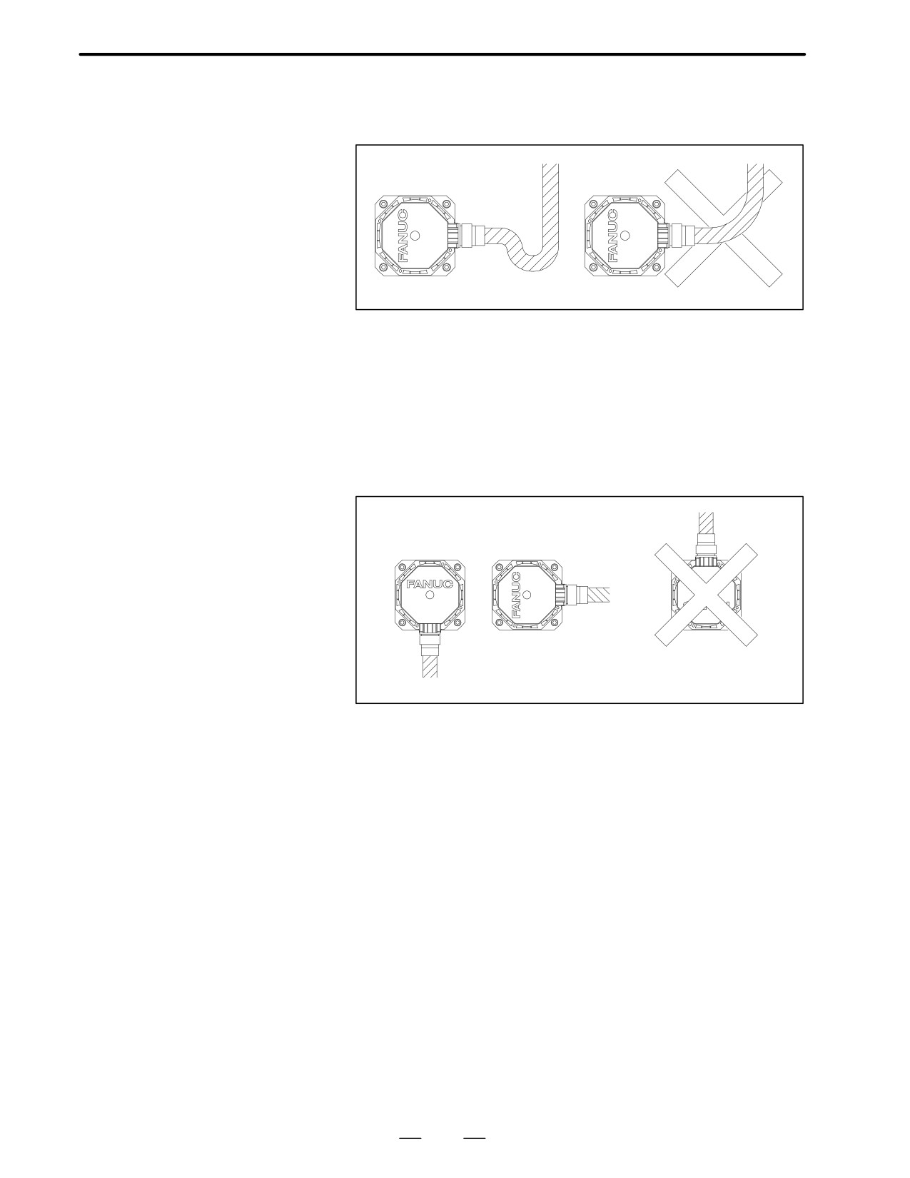
A Prevent the cutting fluid from being led to the motor through the cable.
When the motor connector is used in the up position, put a drip loop
in the cable.
A When the motor connector is up, the cutting fluid is collected in the
cable connector through the cable. Turn the motor connector sideways
or downward as far as possible. Most of the defects caused by the
cutting fluid have occurred in the cable connector.
The standard receptacle on the motor side is waterproof. If the cable
connector will be subjected to moisture, it is recommended that an R
class or waterproof plug be used. Suitable plugs are listed in the cable
plug combination recommendations in Chapter 8. (The standard MS
plug is not waterproof; water is liable to enter the pin section.)
13
2. PRECAUTIONS ON USE
DESCRIPTIONS FOR THE α series
B-65142E/02
Shaft attachment section
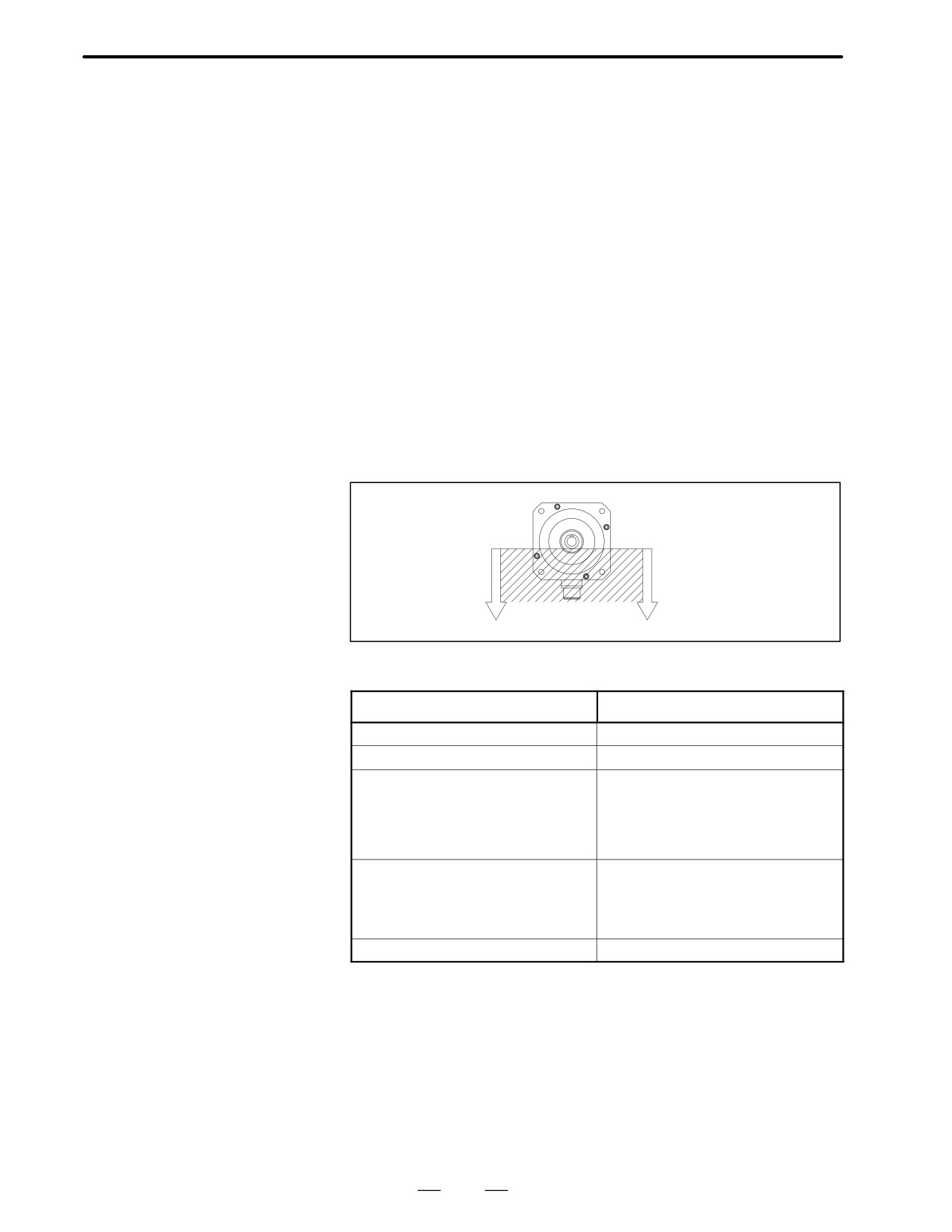
The motor shaft is sealed to prevent penetration of oil into the motor
requirements
housing. However, sealing may not be perfect under severe working
conditions. Observe the following points.
To maintain a constant sealing effect, it is necessary to replace the oil seal
regularly before its lifetime expires. The lifetime of the oil seal greatly
varies with its working environment and conditions.
When oil bath lubrication is provided for the gear engagement, for
example, the oil level must be below the lip of the shaft’s oil seal. Set the
oil level so that oil merely splashes the lip. Thus, as the shaft rotates, the
oil seal can repel oil. If, however, pressure is applied continuously while
the shaft is stopped, oil may penetrate the lip. When the shaft is always
immersed in oil, for example, under the condition that the motor is to be
used with the shaft oriented vertically a special design is required. For
example, another oil seal could be installed on the machine side, and a
drain provided so that oil penetrating that seal can drain off.
When grease is used for lubrication, the oil seal characteristics are usually
lost.
In either case, ensure that no pressure is applied to the oil seal lip.
The motor shaft oil seal diameter is as shown below.
Motor mode
Oil seal diameter
α0.5
φ 9mm
α1/2
φ 15mm
α3/6
φ 24mm
α3/6HV
αC3/6
αM3/6/9
αL3/6/9
α12/22/30/40
φ 35mm
α12/22/30HV
αC12/22
αL25/50
α65/100/150
φ 55mm
14
B-65142E/02
DESCRIPTIONS FOR THE α series
2. PRECAUTIONS ON USE
When the servo motor is delivered, check the following items.
2.6
A The motor meets the specifications.
ACCEPTANCE AND
(Specifications of the model/shaft/detector)
STORAGE
A Damage caused by the transportation.
A The shaft is normal when rotated by hand.
A The brake works.
A Looseness or play in screws.
FANUC servo motors are completely checked before shipment, and the
inspection at acceptance is normally unnecessary. When an inspection is
required, check the specifications (wiring, current, voltage, etc.) of the
motor and detector.
Store the motor indoors. The storage temperature is -20°C to +60°C.
Avoid storing in the following places.
A Place with high humidity so condensation will form.
A Place with extreme temperature changes.
A Place always exposed to vibration.
(The bearing may be damaged.)
A Place with much dust.
15
3. INSTRUCTIONS
DESCRIPTIONS FOR THE α series
B-65142E/02
INSTRUCTIONS
3
16
B-65142E/02
DESCRIPTIONS FOR THE α series
3. INSTRUCTIONS
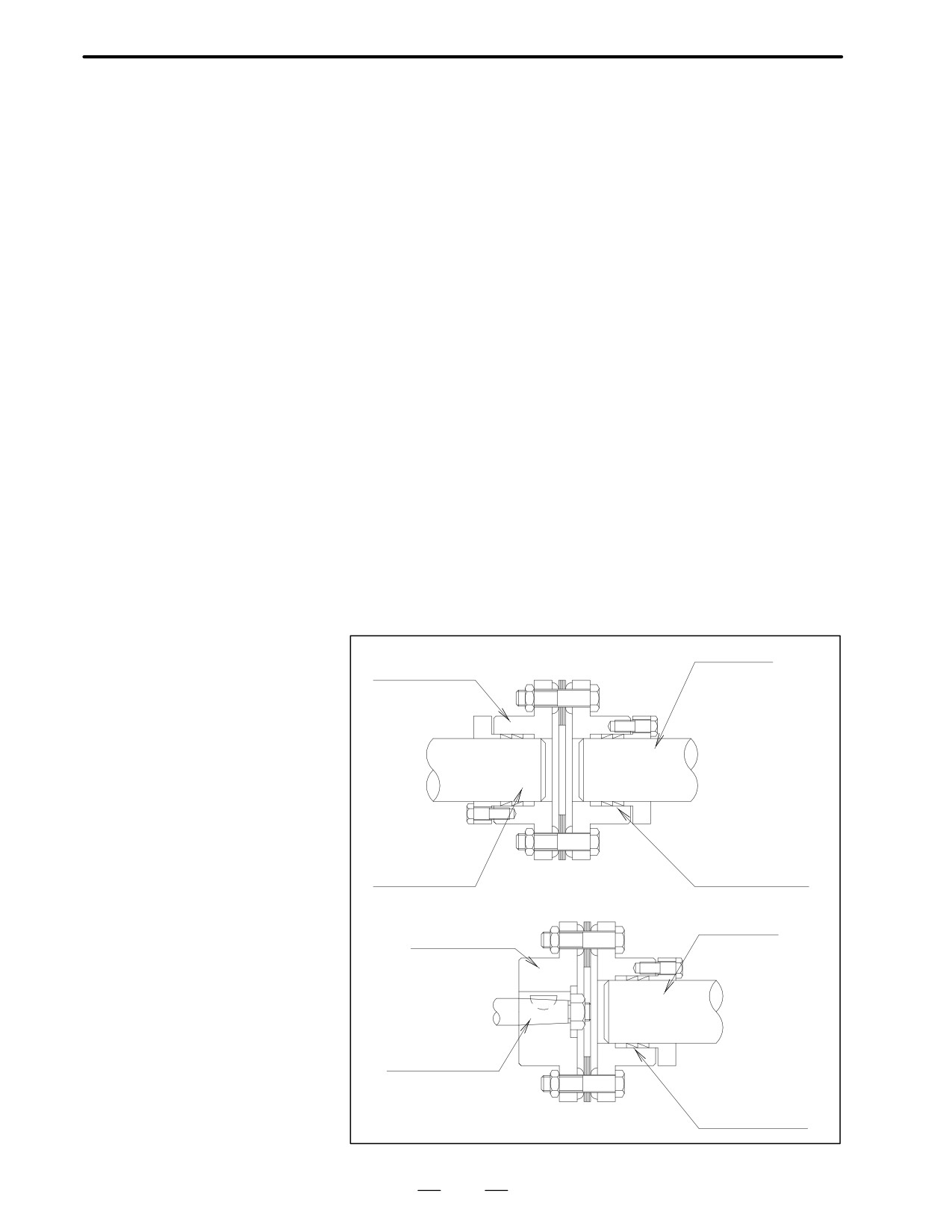
There are four methods for connecting the motor shaft to the ball screw:
3.1
A Direct connection through a flexible coupling
DRIVE SHAFT
A Direct connection through a rigid coupling
COUPLING
A Connection through gears
A Connection through timing belts
It is important to understand the advantages and disadvantages of each
method, and select one that is most suitable for the machine.
Direct connection using
Direct connection by a flexible coupling has the following advantages
a flexible coupling
over connection using gears:
A Even if the angle of the motor shaft to the ball screw changes, it can
be compensated to a certain extent.
A Because a flexible coupling connects elements with less backlash,
driving noise from joints can be significantly suppressed.
However, this method has the following disadvantages:
A The motor shaft and the ball screw must not slide from each other in
the radial direction (for single coupling).
A Loose assembly may result in lower rigidity.
When the motor shaft needs to be connected directly to the ball screw,
connecting them using a flexible coupling facilitates adjustment and
installation of the motor.
To use a single coupling, the machine needs to be designed so that the
centers of the motor shaft and the ball screw are aligned.
If it is difficult to align the centers, a double coupling needs to be
employed.
Ball screw
Flexible coupling
Motor shaft
Locking element
Ball screw
Flexible coupling
Motor shaft
Locking element
17
3. INSTRUCTIONS
DESCRIPTIONS FOR THE α series
B-65142E/02
Direct connection using
Direct connection using a rigid coupling has the following advantages
a rigid coupling
over direct connection using a flexible coupling:
A More economical
A The coupling rigidity can be increased.
A If the rigidity is the same as with a flexible coupling, the inertia can
be reduced.
However, this method has the following disadvantages:
A The motor shaft and the ball screw must not slide from each other in
the radial direction, and the angle of the motor shaft to the ball screw
must be fixed.
For this reason, a rigid coupling needs to be mounted very carefully.
It is desirable that the run-out of the ball screw is 0.01 mm or less. When
a rigid coupling is used on the motor shaft, the run-out of the hole for the
ball screw must be set to 0.01 mm or less by adjusting the tightness of the
span ring.
The run-out of the motor shaft and the ball screw in the radial direction
can be adjusted or compensated to a certain extent by deflection. Note,
however, that it is difficult to adjust or measure changes in the angle.
Therefore, the structure of the machine should be such that precision can
be fully guaranteed.
Gears
This method is used when the motor cannot be put in line with the ball
screw because of the mechanical interference problem or when the
reduction gear is required in order to obtain large torque. The following
attention should be paid to the gear coupling method:
A Grinding finish should be given to the gear, and eccentricity, pitch
error, tooth-shape deviations etc. should be reduced as much as
possible. Please use the JIS, First Class as a reference of precision.
A Adjustment of backlash should be carefully performed. Generally, if
there is too little backlash, a high-pitched noise will occur during
high-speed operation, and if the backlash is too big, a drumming sound
of the tooth surfaces will occur during acceleration/deceleration.
Since these noises are sensitive to the amount of backlash, the structure
should be so that adjustment of backlash is possible at construction
time.
18
B-65142E/02
DESCRIPTIONS FOR THE α series
3. INSTRUCTIONS
Timing belt
A timing belt is used in the same cases as gear connection, but in
comparison, it has advantages such as low cost and reduced noise during
operation, etc. However, it is necessary to correctly understand the
characteristics of timing belts and use them appropriately to maintain
high precision.
Generally, the rigidity of timing belt is sufficiently higher than that of
other mechanical parts such as ball screw or bearing, so there is no danger
of inferiority of performance of control caused by reduction of rigidity by
using timing belt. When using a timing belt with a position detector on
the motor shaft, there are cases where poor precision caused by backlash
of the belt tooth and pulley tooth, or elongation of belt after a long time
becomes problem, so consideration should be given to whether these
errors significantly affect precision. In case the position detector is
mounted behind the timing belt (for example, on the ball screw axis), a
problem of precision does not occur.
Life of the timing belt largely varies according to mounting precision and
tension adjustment. Please refer to the manufacturer’s Instruction Manual
for correct use.
Connection between the
To use a straight shaft that has no key groove, connect the shaft with a
straight shaft and a
coupling using a span ring.
connecting element
Because the span ring connects elements by the friction generated when
the screw is tightened, it is free from backlash and the concentration of
stress. For this reason, the span ring is highly reliable for connecting
elements.
To assure sufficient transmission with the span ring, factors such as the
tightening torque of the screw, the size of the screw, the number of screws,
the clamping flange, and the rigidity of connecting elements are
important. Refer to the manufacturer’s specifications before using the
span ring.
When a coupling or gear is mounted using the span ring, tighten the
screws to remove a run-out of the coupling or gear including the shaft.
19
3. INSTRUCTIONS
DESCRIPTIONS FOR THE α series
B-65142E/02
The machine movement per 1 revolution of motor shaft must be
3.2
determined at the first stage of machine design referring the load torque,
MACHINE
load inertia, rapid traverse speed, and relation between minimum
MOVEMENT PER 1
increment and resolution of the position sensor mounted on the motor
REVOLUTION OF
shaft. To determine this amount, the following conditions should be taken
into consideration.
MOTOR SHAFT
A
The machine movement per 1 revolution of motor shaft (”L”) must be
such that the desired rapid traverse speed can be obtained. For
example, if the maximum motor speed is 1500 rpm and the rapid
traverse speed must be 12 m/min., the amount of ”L” must be 8
mm/rev. or higher.
A
As the machine movement per 1 revolution of motor shaft is reduced,
both the load torque and the load inertia reflected to motor shaft also
decrease.
Therefore, to obtain large thrust, the amount of ”L” should be the
lowest value at which the desired rapid traverse speed can be obtained.
A
Assuming that the accuracy of the reduction gear is ideal, it is
advantageous to make the machine movement per 1 rev. of motor shaft
as low as possible to obtain the highest accuracy in mechanical servo
operations. In addition, minimizing the machine movement per 1 rev.
of motor shaft can increase the servo rigidity as seen from the
machine’s side, which can contribute to system accuracy and
minimize the influence of external load changes.
A
When the machine is operation is characterized by repeated
acceleration/deceleration cycles, a heating problem may occur due to
the current flow caused by the acceleration and deceleration. Should
this occur, the machine travel distance per motor shaft revolution
should be modified. Given optimum conditions, the machine travel
distance per motor shaft revolution is set such that the motor’s rotor
inertia equals the load inertia based on motor shaft conversion. For
machines such as punch presses and PCB drilling machines, the
machine’s travel distance per motor shaft revolution should be set so
as to satisfy this optimum condition as far as possible, while also
considering the rapid traverse rate and increment system.
20
B-65142E/02
DESCRIPTIONS FOR THE α series
4. SELECTING A MOTOR
SELECTING A MOTOR
4
When selecting an applicable motor, the load, rapid traverse feedrate,
increment system, and other conditions must be considered. This section
describes how to calculate the load and other conditions, showing an
example of a table with a horizontal axis.
A motor is subjected to two types of load: load torque (including friction)
and load inertia. Calculate the two loads accurately and select a motor that
satisfies the following conditions:
Condition 1
When the machine is operating without any load, the torque is
lower than or equal to the continuous torque rating.
If the rated torque is exceeded because of an increase in the friction
coefficient when the machine tool is stopped or operated at an
extremely low speed, the motor may be overheated by the current
flowing when the machine tool is stopped. If the rated torque is
exceeded due to viscosity when the machine tool is operated at a high
speed, a sufficient acceleration torque may not be obtained, resulting
in need for a considerable increase in the acceleration time constant.
(It would appear that no current flows through the motor when the
machine tool stops. Actually, however, a current continuously flows
to balance the torque with the friction produced at a low speed.)
Condition 2
Acceleration can be made with a desired time constant.
Generally, the load torque helps deceleration. If acceleration can be
executed with a desired time constant, deceleration can be made with
the same time constant. Calculate the acceleration torque and check
that the torque required for acceleration is within the intermittent
operating zone of the motor.
Condition 3
The frequency of positioning in rapid traverse is set to a desired
value. The greater the frequency of positioning in rapid traverse, the
greater the ratio of acceleration time to the entire operation time. This
may overheat the motor. When the acceleration time constant is
increased according to the rapid traverse feedrate and positioning
frequency constant, the amount of produced heat decreases in inverse
proportion to the acceleration time constant.
Condition 4
If the load condition varies during a single cycle, the
root-mean-square value of the torques is smaller than or equal to
the rated torque.
Condition 5
The time for which the table can be moved with the maximum
cutting torque (percentage duty cycle and ON time) is within a
desired range.
The procedure for selecting a motor is described below:
21
4. SELECTING A MOTOR
DESCRIPTIONS FOR THE α series
B-65142E/02
This section describes the procedure for selecting a servo motor best
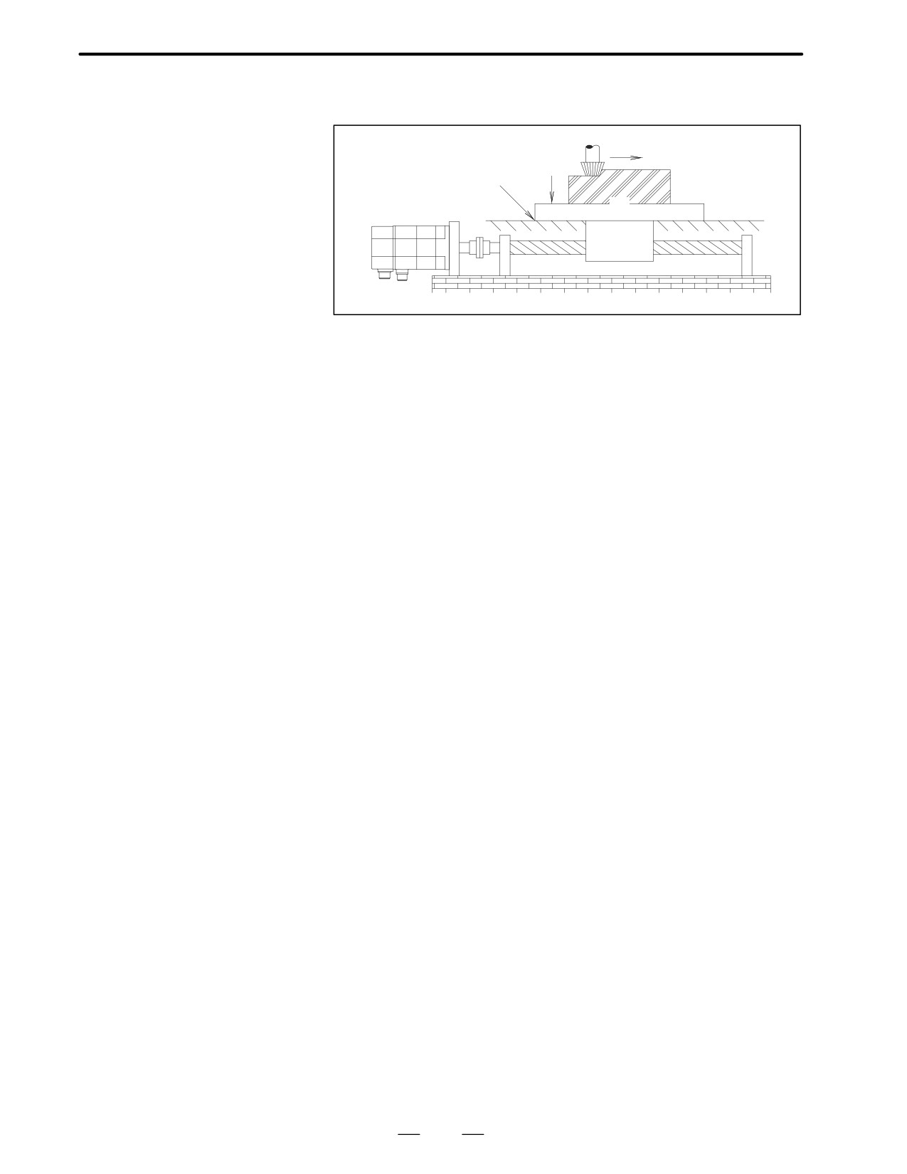
4.1
suited for a table with a horizontal axis (figure below).
CALCULATING
CONDITIONS FOR
fg
Fc
SELECTING A
µ
MOTOR
W
Sample mechanical
W
: Weight of movable parts (table and workpiece) (kgf) = 1000 (kgf)
specifications of the
µ
: Friction coefficient of the sliding surface = 0.05
table and workpiece
π
: Efficiency of the driving system (including a ball screw) = 0.9
fg
: Gib fastening force (kgf) = 50 (kgf)
Fc
: Thrust counter force caused by the cutting force (kgf) = 100 (kgf)
Fcf
: Force by which the table is pressed against the sliding surface,
caused by the moment of cutting force (kgf) = 30 (kgf)
Z1/Z2 : Gear reduction ratio = 1/1
Sample specifications of
Db
: Shaft diameter = 32 (mm)
the feed screw
Lb
: Shaft length = 1000 (mm)
(ball screw)
P
: Pitch = 8 (mm)
Sample specifications of
Ta
: Acceleration torque (kgf⋅cm)
the operation of the
Vm
: Motor speed in rapid traverse (min-1)= 3000 (min-1)
motor shaft
ta
: Acceleration time (s) = 0.10 (s)
JM
: Motor inertia (kgf⋅cm⋅sec2)
JL
: Load inertia (kgf⋅cm⋅sec2)
ks
: Servo position loop gain (sec-1) = 30 (sec-1)
22
B-65142E/02
DESCRIPTIONS FOR THE α series
4. SELECTING A MOTOR
4.1.1
Calculating the Load
Torque and Load
Inertia
Calculating the load
The load torque applied to the motor shaft is generally given by the
torque
following equation:
Tm EFAL
C Tf
2CA
Tm : Load torque applied to the motor shaft (Nm)
F
: Force required to move a movable part (table or tool post) along
the axis (kgf)
L
: Traveling distance of the machine tool per revolution of the mo-
tor = P x (Z1/Z2) = 8 (mm)
T f:Friction torque of the nut of the ball screw or bearing applied to
the motor shaft = 2 (Nm)
F depends on the weight of the table, friction coefficient, whether cutting
is in progress, and whether the axis is horizontal or vertical. If the axis
is vertical, F also depends on the presence of a counterbalance. For a table
with a horizontal axis, F is calculated as follows:
When cutting is not executed:
F = µ (W + fg)
Example)
F = 0.05 A (1000 + 50) = 52.5 (kgf)
Tm = (52.5 A 0.8)/(2 A µ A 0.9) + 2 = 9.4 (kgf⋅cm) = 0.9 (Nm)
When cutting is in progress:
F = Fc + µ (W + fg + Fcf)
Example)
F = 100 + 0.05 A (1000 + 50 + 30) = 154 (kgf)
Tmc = (154 A 0.8)/(2 A µ A 0.9) + 2 = 21.8 (kgf⋅cm) = 2.1 (Nm)
To satisfy condition 1, check the data sheet and select a motor whose load
torque (rated torque at stall) when cutting is not executed is 0.9 (Nm) or
higher and the maximum speed is 3000 (min-1) or higher. Considering
the acceleration/deceleration conditions, provisionally select α2/3000
(rated torque at stall is 2.0 (Nm)).
!Notes
When calculating the torque, take the following precautions:
A Allow for the friction torque caused by the gib fastening force (fg).
The torque calculated only from the weight of a movable part and the
friction coefficient is generally quite small. The gib fastening force
and precision of the sliding surface may have a great effect on the
torque.
A The pre-load of the bearing or nut of the ball screw, pre-tension of the
screw, and other factors may make Fc of the rolling contact
considerable. In a small, lightweight machine tool, the friction torque
will greatly affect the entire torque.
23
4. SELECTING A MOTOR
DESCRIPTIONS FOR THE α series
B-65142E/02
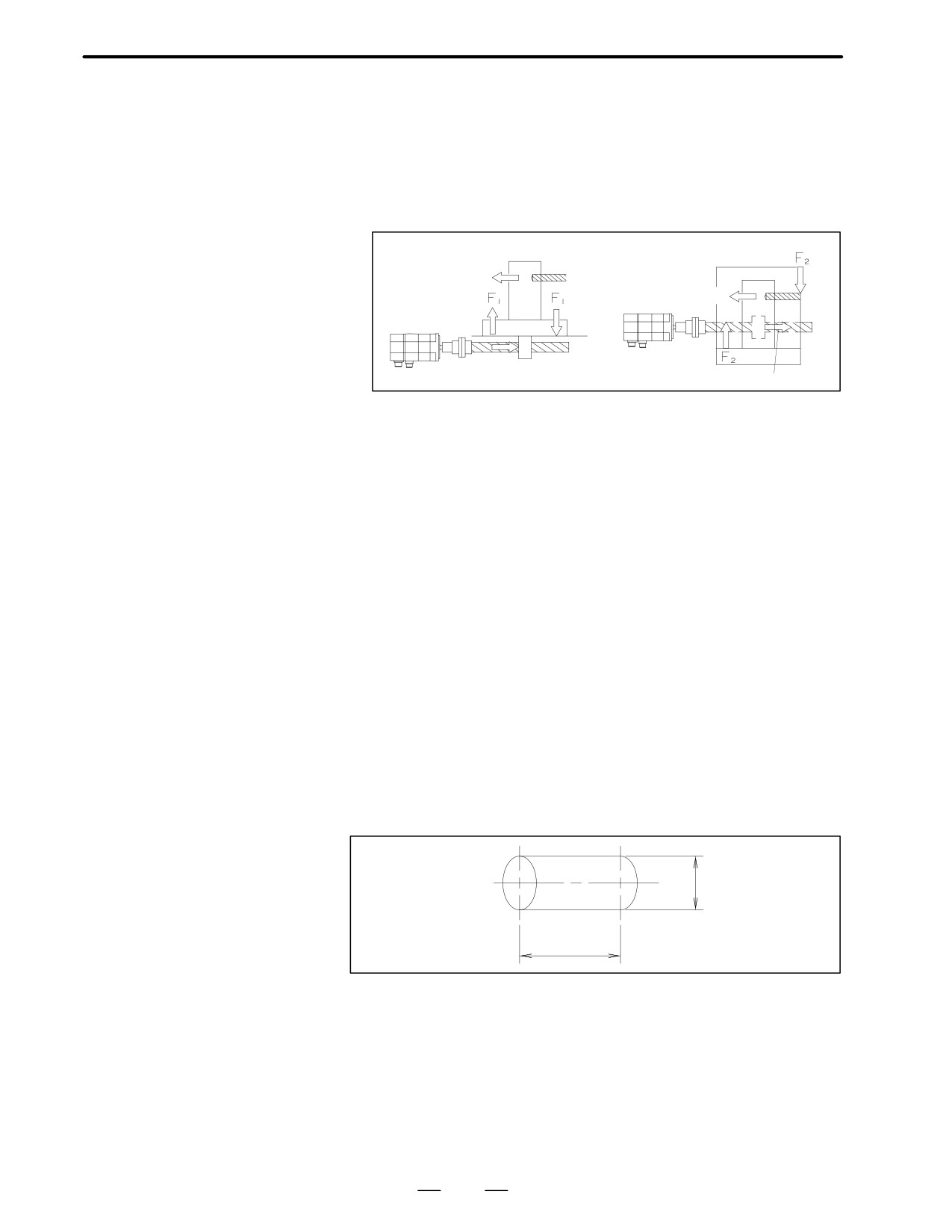
A Allow for an increase in friction on the sliding surface (Fcf) caused by
the cutting resistance. The cutting resistance and the driving force
generally do not act through a common point as illustrated below.
When a large cutting resistance is applied, the moment increases the
load on the sliding surface.
When calculating the torque during cutting, allow for the friction
torque caused by the load.
Cutting force
Cutting force
Driving force
Driving force
A The feedrate may cause the friction torque to vary greatly. Obtain an
accurate value by closely examining variations in friction depending
on variations in speed, the mechanism for supporting the table (sliding
contact, rolling contact, static pressure, etc.), material of the sliding
surface, lubricating system, and other factors.
A The friction torque of a single machine varies widely due to
adjustment conditions, ambient temperature, and lubrication
conditions. Collect a great amount of measurement data of identical
models so that a correct load torque can be calculated. When adjusting
the gib fastening force and backlash, monitor the friction torque.
Avoid generating an unnecessarily great torque.
Calculating the load
Unlike the load torque, an accurate load inertia can be obtained just by
inertia
calculation. The inertia of all objects moved by the revolution of a driving
motor forms the load inertia of the motor. It does not matter whether the
object is rotated or moved along a straight line. Calculate the inertia
values of individual moving objects separately, then add the values
together, according to a rule, to obtain the load inertia. The inertia of
almost all objects can be calculated according to the following basic rules:
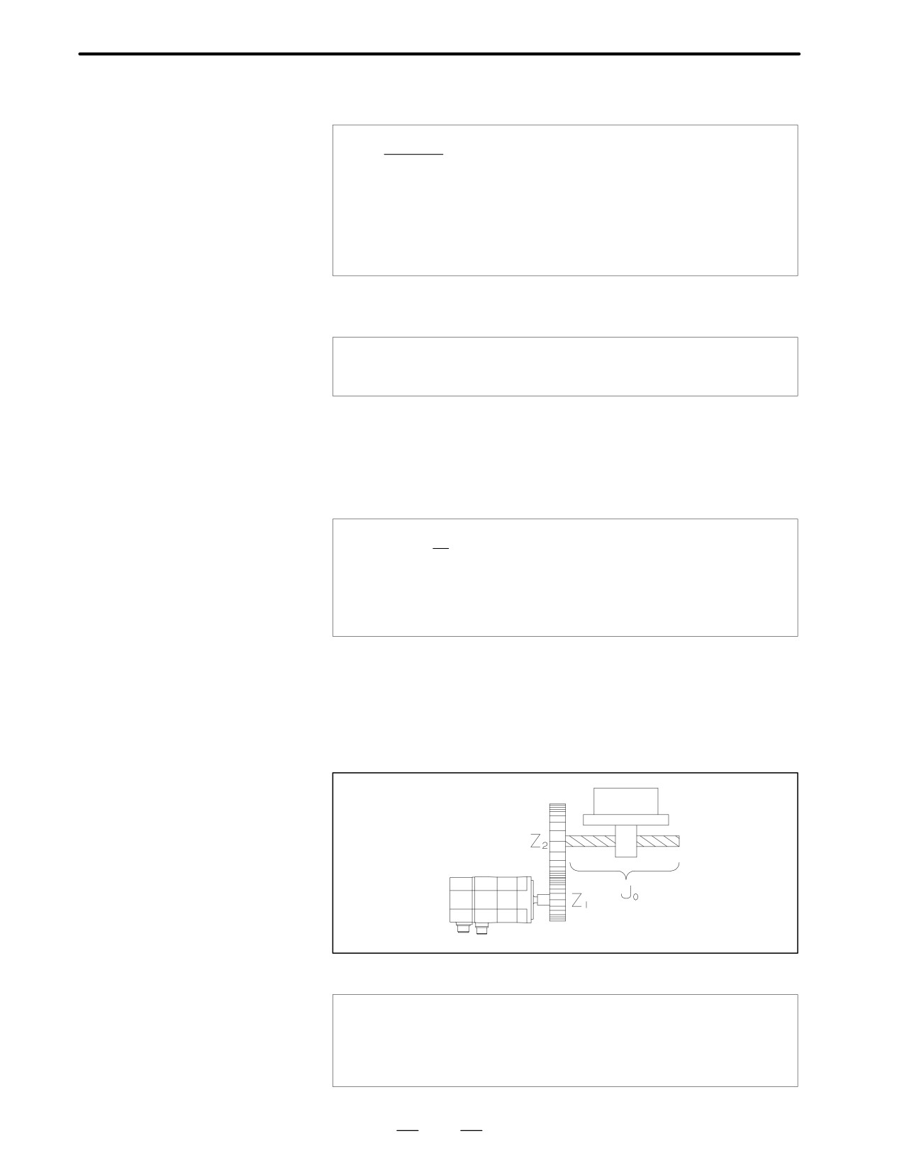
A Inertia of a cylindrical
object (ball screw, gear,
coupling, etc.)
D (cm)
L (cm)
24
B-65142E/02
DESCRIPTIONS FOR THE α series
4. SELECTING A MOTOR
The inertia of a cylindrical object rotating about its central axis is
calculated as follows:
)g
J+
(kgf⋅cm⋅sA)
32 a 980Db4Lb
J
: Inertia (kgf⋅cm⋅s2)
γ
: Weight of the object per unit volume (kg/cm3)
Db : Diameter of the object (cm)
Lb
: Length of the object (cm)
If the object is made of steel (γ = 7.8a10-3 kg/cm3), an approximation
of the inertia is:
J + 0.78 a 10-6Db4Lb
(kgf⋅cm⋅sA)
Example)
When Db is 32 (mm) and Lb is 1000 (mm), inertia Jb of the shaft of
a ball screw is calculated as follows:
Jb = 0.78a10-6a3.24a100 = 0.0082 (kg⋅cm⋅s2)
A Inertia of a heavy object
moving along a straight
line (table, workpiece,
W
J+
(kgf⋅cm⋅sA)
980a
2))2
etc.)
W : Weight of the object moving along a straight line (kg)
L
: Traveling distance along a straight line per revolution
of the motor (cm)
Example)
When W is 1000(kg) and L is 8(mm), Jw of a table and workpiece is
calculated as follows:
Jw = 1000/980a(0.8/2/π)2 = 0.0165(kgf⋅cm⋅s2)
A Inertia of an object
whose speed is
increased above or
decreased below the
speed of the motor shaft
The inertia applied to the motor shaft by inertia Jo is calculated as follows:
J+(Z1)2 aJo
(kgf⋅cm⋅sA)
Z2
J0: Inertia before the speed is changed (kgf⋅cm⋅s2)
25
4. SELECTING A MOTOR
DESCRIPTIONS FOR THE α series
B-65142E/02
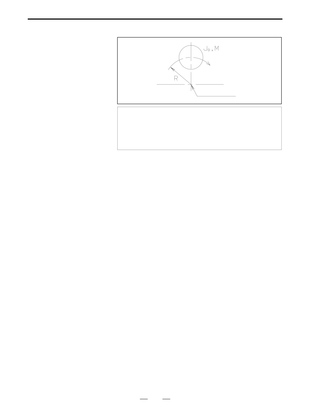
A Inertia of a cylindrical
object in which the
center of rotation is
displaced
Center of rotation
M
J+Jo )
(kgf⋅cm⋅sA)
980R2
J0
: Inertia around the center of the object (kgf⋅cm⋅s2)
M
: Weight of the object (kg)
R
: Radius of rotation (cm)
The above equation is used to calculate the inertia of, for example, a large
gear which is hollowed out in order to reduce the inertia and weight.
The sum of the inertia values calculated above is J (load inertia) for
accelerating the motor.
In this example, the sum of Jb and Jw obtained in above is load inertia JL.
JL = 0.0082 + 0.0165 = 0.0247 (kgf⋅cm⋅s2)
A Note
Limitations on
The load inertia has a great effect on the controllability of the motor as
load inertia
well as the time for acceleration/deceleration in rapid traverse. When the
load inertia is increased, the following two problems may occur: When
a command is changed, it takes more time for the motor to reach the speed
specified by the new command. When a machine tool is moved along two
axes at a high speed to cut an arc or curve, a larger error occurs.
When the load inertia is smaller than or equal to the rotor inertia of the
motor, those problems will not occur. When the load inertia is up to three
times the rotor inertia, the controllability may have to be lowered a little.
Actually, this will not adversely affect the operation of an ordinary metal
cutting machine. If a router for woodworking or a machine to cut a curve
at a high speed is used, it is recommended that the load inertia be smaller
than or equal to the rotor inertia.
If the load inertia much larger than three times the rotor inertia, the
controllability will be lowered significantly. If the load inertia much
larger than three times the rotor inertia, an adjustment in the normal range
may be insufficient. Avoid using a machine with such a great load inertia.
If the machine design does not allow a smaller load inertia, contact a
FANUC engineer.
26