FANUC I/O Unit-MODEL A. CONNECTION AND MAINTENANCE MANUAL (B-61813E/04) - page 6
9.TEMPERATURE INPUT MODULE CONNECTION
B-61813E/04
Abnormality data
If an abnormality occurs in the input data or in the module, the DI13 bit
(status signal) becomes "1", resulting in the display changing from
temperature input data to abnormality data. Abnormality data is
assigned to these bits as listed below:
DI00 : CH1 input out of scale--the current temperature falls
outside the measurable range.
DI01 : CH1 input burn-out--the cable or connector has been
detached.
DI02 : CH3 input out of scale--the current temperature falls
outside the measurable range.
DI03 : CH3 input burn-out--the cable or connector has been
detached.
DI04 : Cold-junction abnormality (only for thermocouple-type
input module)--the temperature of the terminal board unit
falls outside the measurable range.
DI05 : System error--the internal circuit is abnormal.
DI06 : Wrong module--other than the correct module has been
installed.
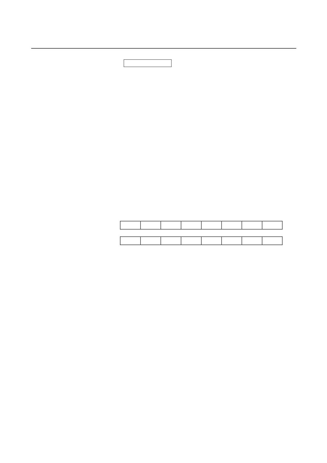
(2) Status signals, CH2 temperature data, CH4 temperature data, or
abnormality data
DI23
DI22
DI21
DI20
DI19
DI18
DI17
DI16
DI31
DI30
DI29
DI28
DI27
DI26
DI25
DI24
•
Status signals
DI129 : Abnormality sign bit
1 : This bit becomes "1" when the temperature
input becomes abnormal. DI16 to DI28 are
used to describe the abnormality.
0 : DI16 to DI28 are used to indicate the
temperature data.
DI30 : CH2 data READY
1 : Read the CH2 temperature data from DI16
to DI28 when this bit is set to "1".
DI31 : CH4 data READY
1 : Read the CH4 temperature data from DI16
to DI28 when this bit is set to "1".
• CH2 temperature data, CH4 temperature data, or abnormality
data
DI16 (LSB) to DI28 (MSB):
These bits indicate temperature input data
(CH2/CH4) or abnormality data.
- 152 -
B-61813E/04
CONNECTION
9.TEMPERATURE INPUT MODULE
Temperature input data
The temperature input data is in binary. It is ten times the actual
temperature.
Example
(41F3h → 0499 → 49.9°C)
The highest three bits are status signals.
For a thermoresistance-type module (ATI04A), the DI28 bit is a sign bit.
(Negative data is represented in two's complement.)
Example
(5FFBh → -0.5°C)
The highest three bits are status signals.
Abnormality data
If an abnormality occurs in the input data or the module, the DI29 bit
(status signal) is set to "1", resulting in the display changing from
temperature input data to abnormality data. Abnormality data is
assigned to these bits as listed below:
DI16 : CH2 input out of scale--the current temperature falls
outside the measurable range.
DI17 : CH2 input burn-out--the cable or connector has been
detached.
DI18 : CH4 input out of scale--the current temperature falls
outside the measurable range.
DI19 : CH4 input burn-out--the cable or connector has been
detached.
DI20 : Cold-junction abnormality (only for thermocouple-type
input module)--the temperature of the terminal board unit
falls outside the measurable range.
DI21 : System error--the internal circuit is abnormal.
DI22 : Wrong module--other than the correct module has been
installed.
- 153 -
9.TEMPERATURE INPUT MODULE CONNECTION
B-61813E/04
9.4
COMPLETE CONNECTION OF TEMPERATURE INPUT
MODULE
9.4.1
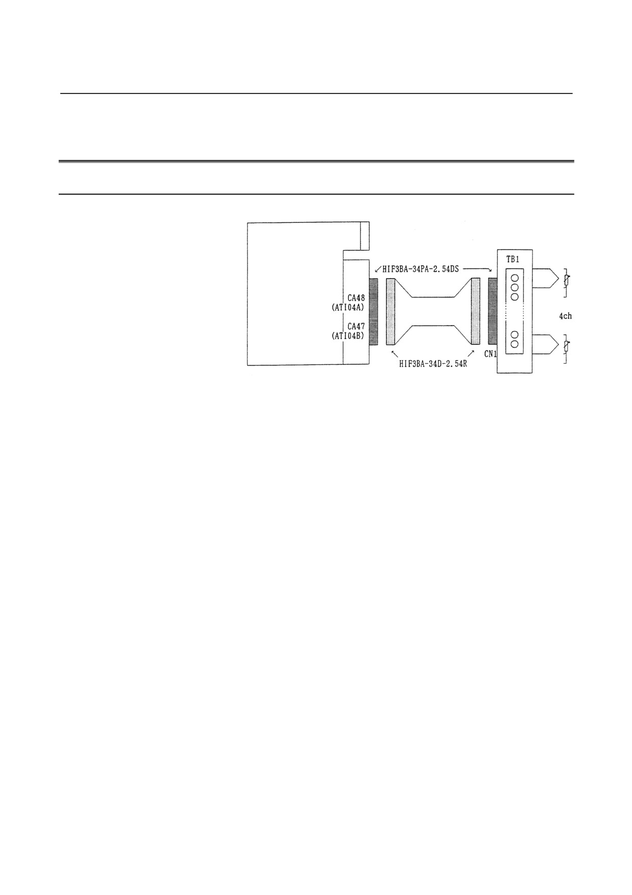
Temperature Input Module Connection Diagram
Temperature sensors
•Thermoresistance
Temperature input module
•J/K thermocouple
Hirose Electric Co., Ltd.
Cable
Hirose
Electric Co., Ltd.
Terminal board unit
(There are two types of terminal board units, the first for a
thermoresistance-type module and the second for a thermocouple-type
module.)
See Section 9.7 for explanations about the dimensions of the terminal board.
- 154 -
B-61813E/04
CONNECTION
9.TEMPERATURE INPUT MODULE
9.4.2
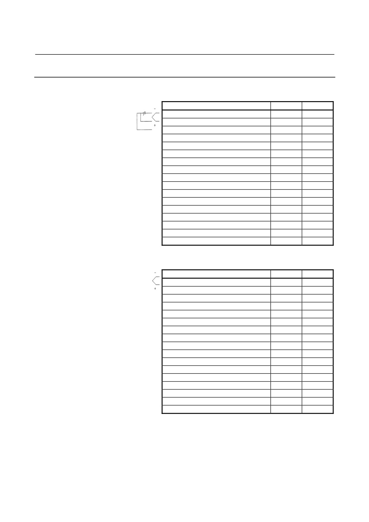
Connector Signal Lists
(1)
Thermoresistance input module
ATI04A
Channel
Pin No.
Pin No.
Channel 1 -
1A
1B
Channel 1 +
2A
2B
Channel 1 +
3A
3B
Channel 2 -
4A
4B
Channel 2 +
5A
5B
Channel 2 +
6A
6B
Channel 3 -
7A
7B
Channel 3 +
8A
8B
Channel 3 +
9A
9B
Channel 4 -
10A
10B
Channel 4 +
11A
11B
Channel 4 +
12A
12B
Unusable
13A
13B
Unusable
14A
14B
Unusable
15A
15B
Unusable
16A
16B
Unusable
17A
17B
(2)
Thermocouple input module
ATI04B
Channel
Pin No.
Pin No.
Channel 1 -
1A
1B
Channel 1 +
2A
2B
Unusable
3A
3B
Channel 2 -
4A
4B
Channel 2 +
5A
5B
Unusable
6A
6B
Channel 3 -
7A
7B
Channel 3 +
8A
8B
Unusable
9A
9B
Channel 4 -
10A
10B
Channel 4 +
11A
11B
Unusable
12A
12B
Cold-junction compensation element A
13A
13B
Cold-junction compensation element B1
14A
14B
Cold-junction compensation element B2
15A
15B
Unusable
16A
16B
Unusable
17A
17B
- 155 -
9.TEMPERATURE INPUT MODULE CONNECTION
B-61813E/04
9.4.3
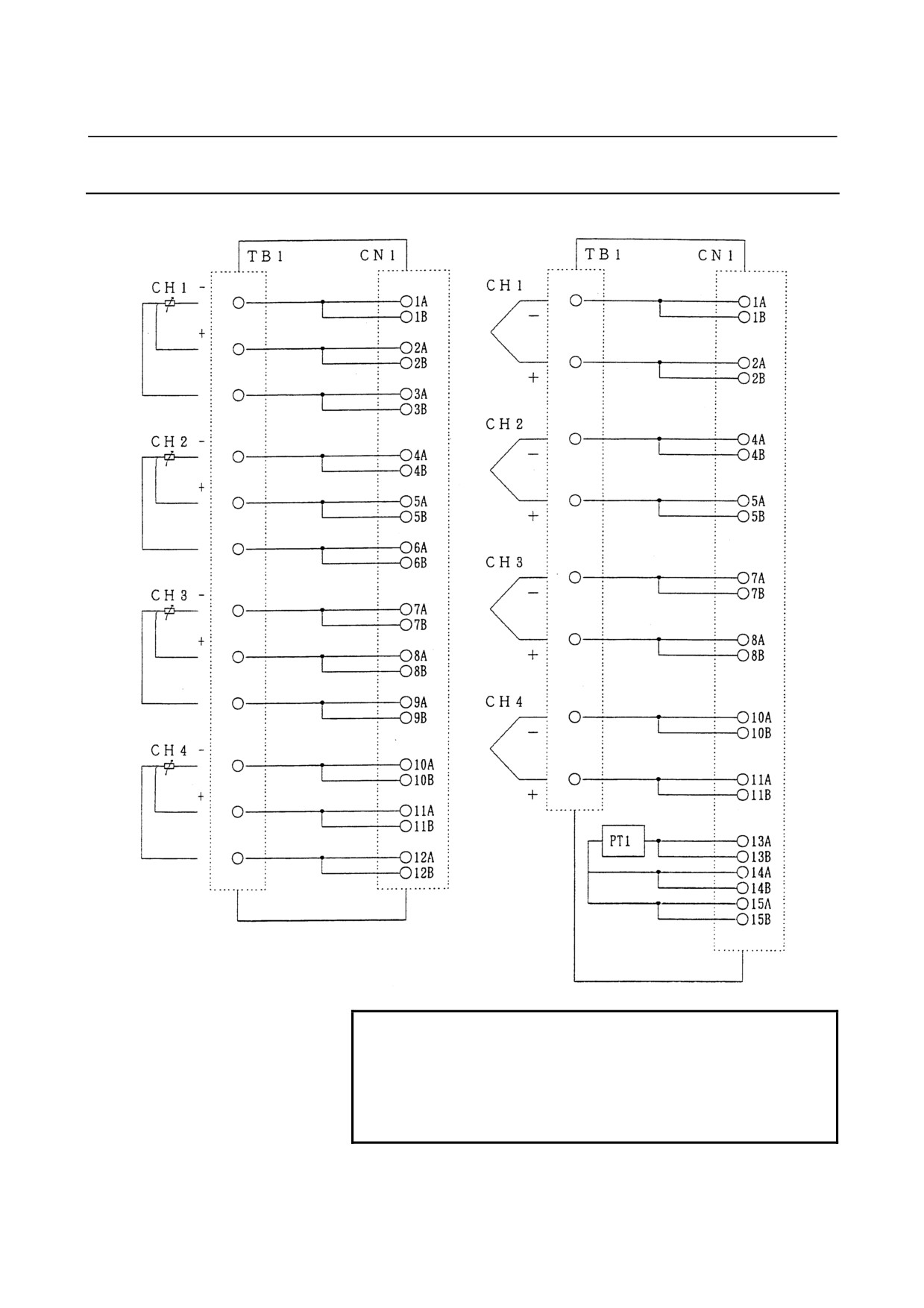
Terminal Board Unit Connection Diagram
For thermoresistance-type module (ATB01A)
For thermocouple-type module (ATB01B)
Terminal board
Connector Terminal board
Connector
NOTE
The thermocouple module ATB01B incorporates a
cold-junction compensation device (PT1). It is
essential to temperature measurement with a
thermocouple. Use the ATB01B whenever the
ATI04B is used.
- 156 -
B-61813E/04
CONNECTION
9.TEMPERATURE INPUT MODULE
9.5
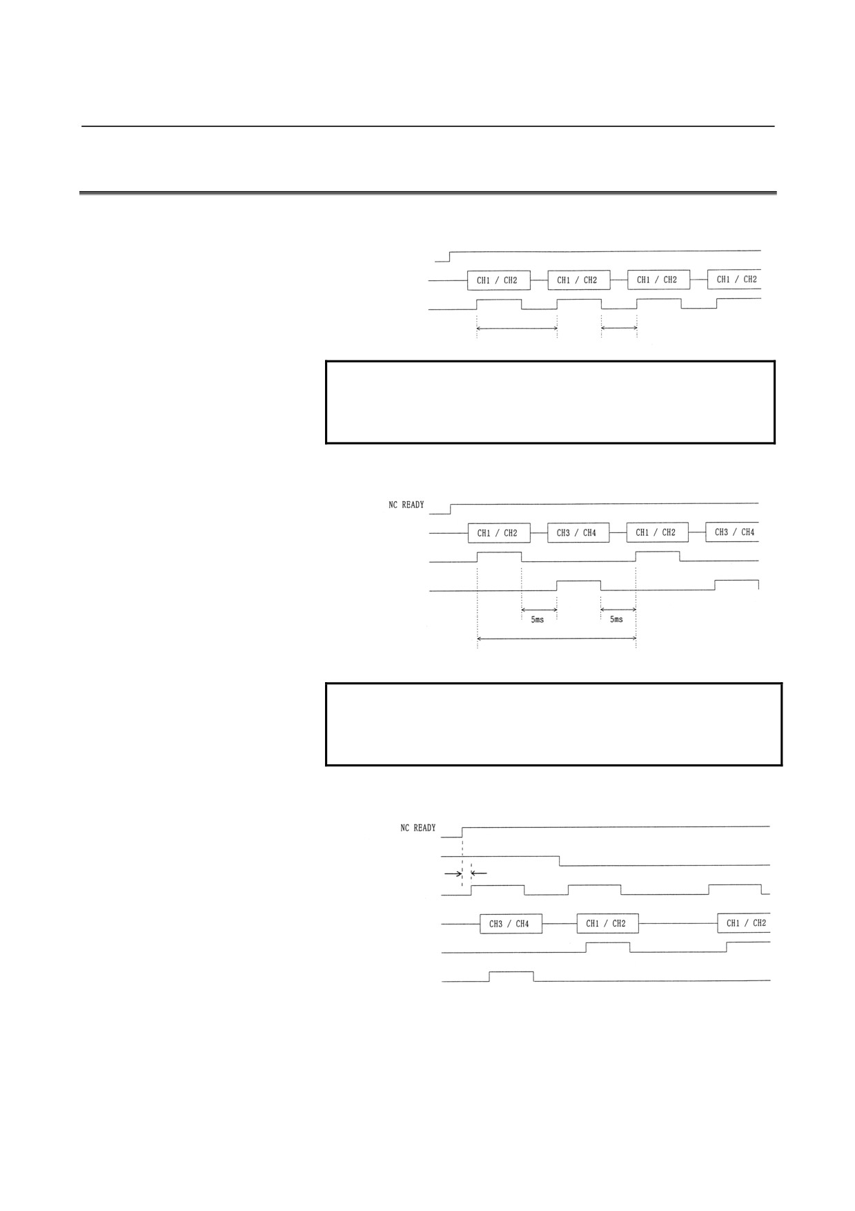
TIMING CHARTS
(1)
2-channel mode
NC READY
Temperature data
CH1/CH2 data
READY
0.3s (Note)
5ms
NOTE
The actual response time is the sum of the time
required to pass the filter and the scan time that is
determined depending on the system.
(2)
4-channel automatic measurement mode
Temperature data
CH1/CH2 data
READY
CH3/CH4 data
READY
Specified period (0.5 to 10 s)
(Note)
NOTE
The actual response time is the sum of the time
required to pass the filter and the scan time that is
determined depending on the system.
(3)
4-channel manual measurement mode
Channel select
1 s or longer
READ request
Temperature
data
CH1/CH2 data
READY
CH3/CH4 data
READY
- 157 -
9.TEMPERATURE INPUT MODULE CONNECTION
B-61813E/04
9.6
MEASUREMENT EXAMPLES
(1)
2-channel mode
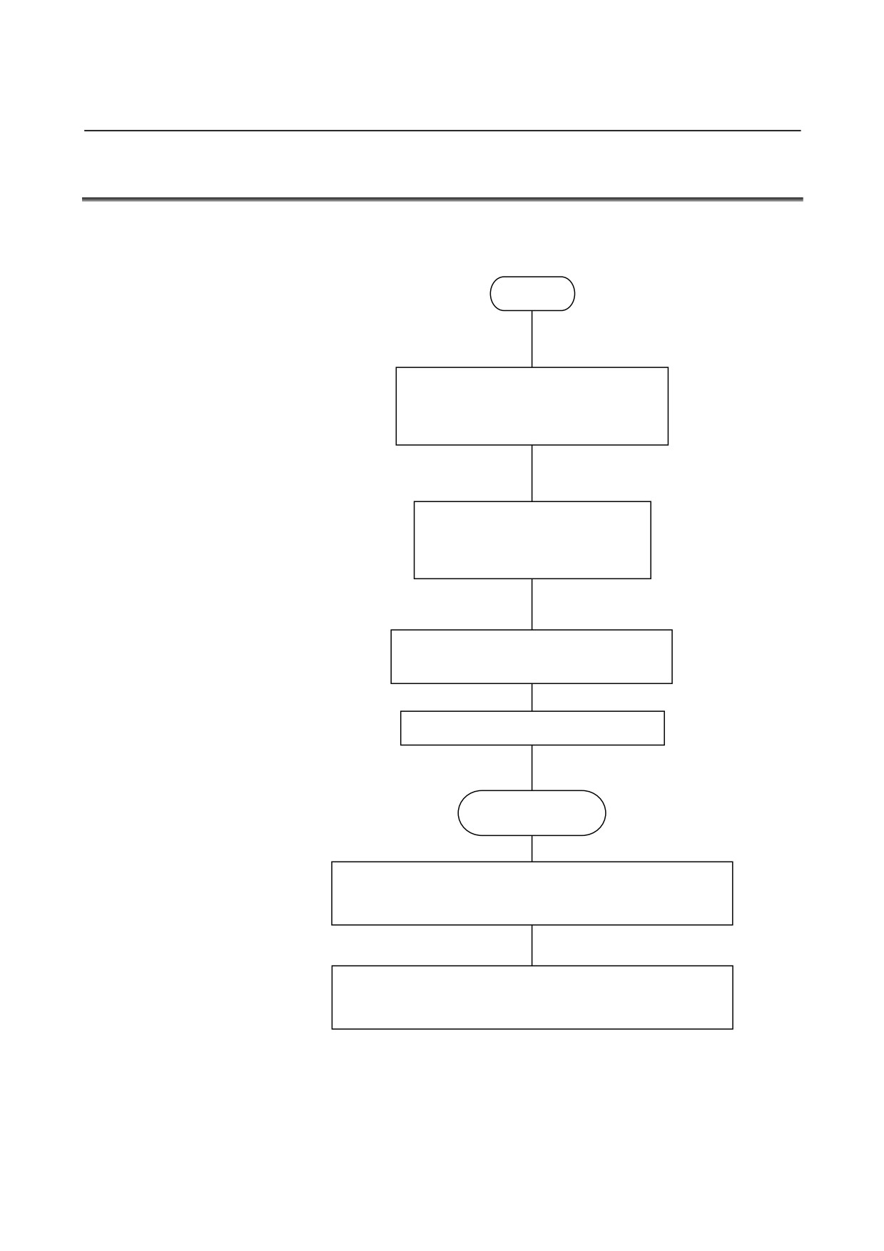
(a) Flowchart
START
*Check that NC READY
(DO16) and DO19 are "0".
Specify the module type (DO17).
0 : Thermocouple module
1 : Thermoresistance module
Specify the sensor type (DO18).
0 : Pt/K
1 : JPt/J
Reset the number of channels bit
(DO24) to "0".
Set NC READY (DO16) to "1".
Now ready to
measure.
When CH1 data READY (DI14 of input signal) becomes
"1", input signals DI00 to DI12 represent CH1 data.
When CH2 data READY (DI30 of input signal) becomes
"1", input signals DI16 to DI28 represent CH2 data.
- 158 -
B-61813E/04
CONNECTION
9.TEMPERATURE INPUT MODULE
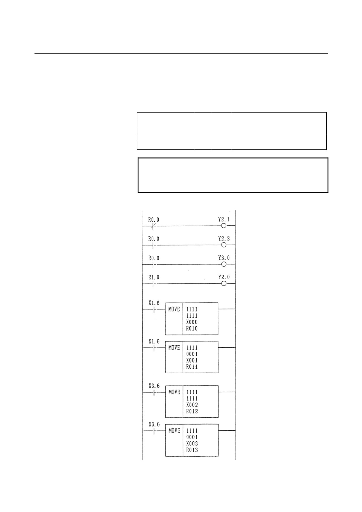
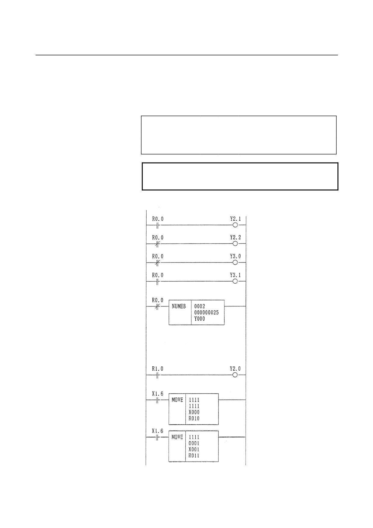
(b) Ladder example
The following measurement and ladder examples apply
when a thermoresistance module with Pt is used for
measurement.
PMC measurement
GROUP BASE SLOT NAME
GROUP BASE SLOT NAME
X000
0
0
1
/4
Y000
0
0
1
/4
X001
0
0
1
/4
Y001
0
0
1
/4
X002
0
0
1
/4
Y002
0
0
1
/4
X003
0
0
1
/4
Y003
0
0
1
/4
NOTE
Set the ladder scan time to 0.25 s or less.
This example of ladder use is for the second level.
R0.0 is used as a normally open relay.
Ladder
Specify the module.
(thermoresistance-type module)
Specify the sensor (Pt).
Specify the number of channels (two
channels).
NC READY (When R1.0 becomes
"1", NC READY becomes "1" to start
measurement.)
When CH1 data READY is "1", CH1
temperature data is sent to R010 to
R011.
When CH2 data READY is "1", CH2
temperature data is sent to R012 to
R013.
- 159 -
9.TEMPERATURE INPUT MODULE CONNECTION
B-61813E/04
(2)
4-channel automatic measurement mode
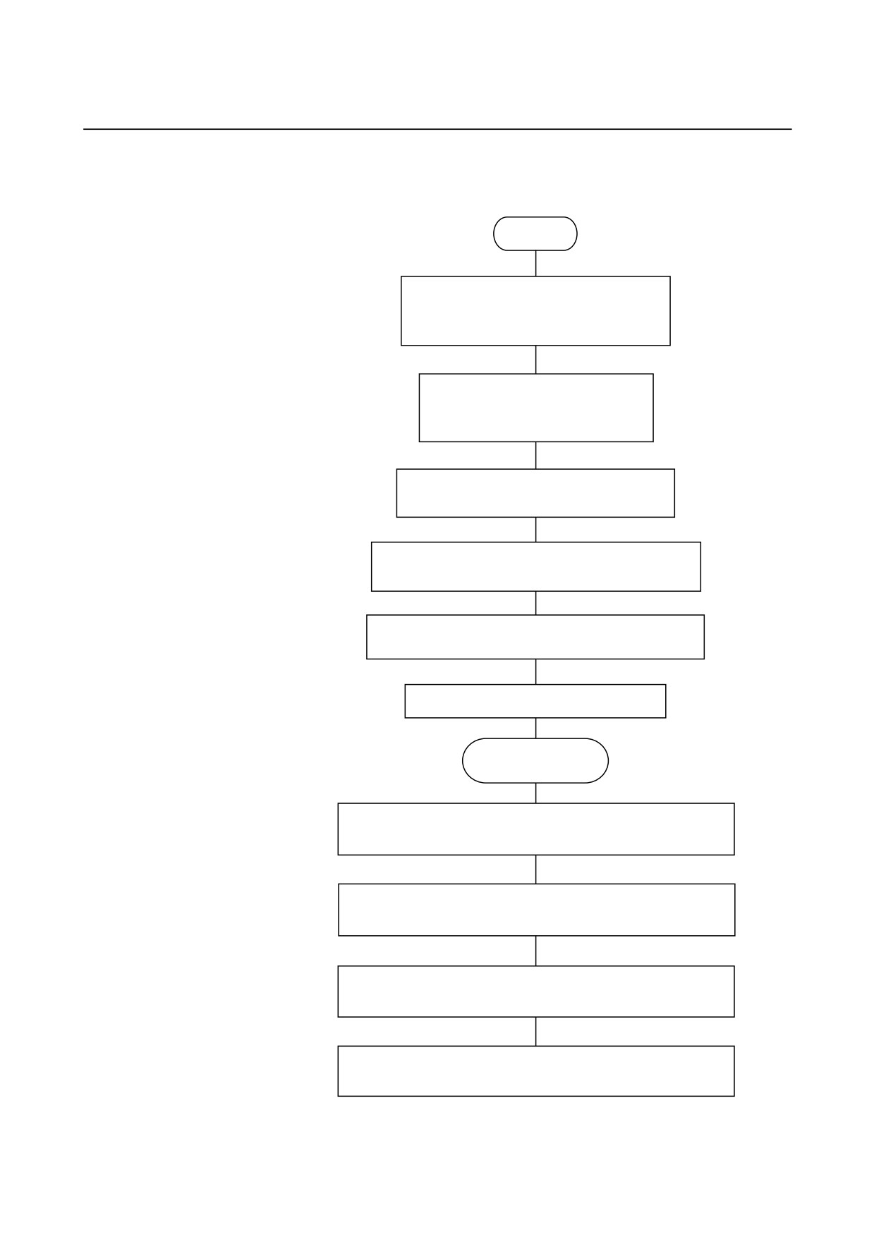
(a) Flowchart
START
* Check that NC READY
(DO16) and DO19 are "0".
Specify the module type (DO17).
0 : Thermocouple module
1 : Thermoresistance module
Specify the sensor type (DO18).
0 : Pt/K
1 : JPt/J
Set the number of channels bit (DO24) to
"1".
Set the 4-channel mode specification bit (DO25)
to "0".
Specify the channel switching period (DO00 to
DO15).
Set NC READY (DO16) to "1".
Now ready to
measure.
When CH1 data READY (DI14 of input signal) becomes
"1", input signals DI00 to DI12 represent CH1 data.
When CH2 data READY (DI30 of input signal) becomes
"1", input signals DI16 to DI28 represent CH2 data.
When CH3 data READY (DI15 of input signal) becomes
"1", input signals DI00 to DI12 represent CH3 data.
When CH4 data READY (DI31 of input signal) becomes
"1", input signals DI16 to DI28 represent CH4 data.
- 160 -
B-61813E/04
CONNECTION
9.TEMPERATURE INPUT MODULE
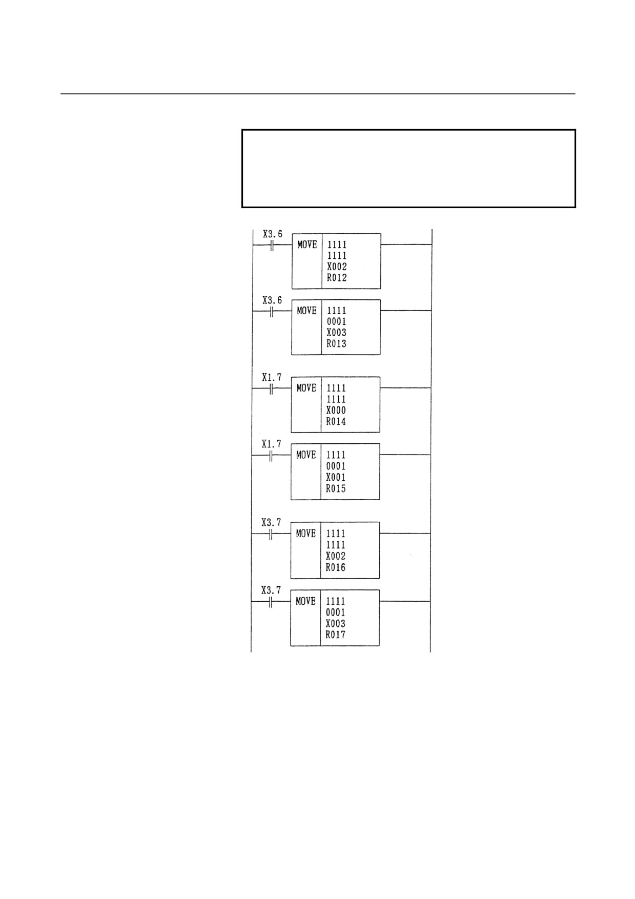
(b) Ladder example
The following measurement and ladder examples apply
when a J thermocouple module is used for measurement.
PMC assignment
GROUP BASE SLOT NAME
GROUP BASE SLOT NAME
X000
0
0
1
/4
Y000
0
0
1
/4
X001
0
0
1
/4
Y001
0
0
1
/4
X002
0
0
1
/4
Y002
0
0
1
/4
X003
0
0
1
/4
Y003
0
0
1
/4
NOTE
This example of ladder use is for the second level.
R0.0 is used as a normally open relay.
Ladder
Specify the module.
(thermocouple-type module)
Specify the sensor
(J thermocouple).
Specify the number of channels (four
channels).
Specify a 4-channel mode (automatic
measurement).
Specify the channel switching period
for 4-channel automatic
measurement.
Specify 0025 to provide a period of 2.5
s.(Note)
NC READY (When R1.0 is set to "1",
NC READY becomes "1" to start
measurement.)
When CH1 data READY is set to "1",
CH1 temperature data is sent to R010
to R011.
- 161 -
9.TEMPERATURE INPUT MODULE CONNECTION
B-61813E/04
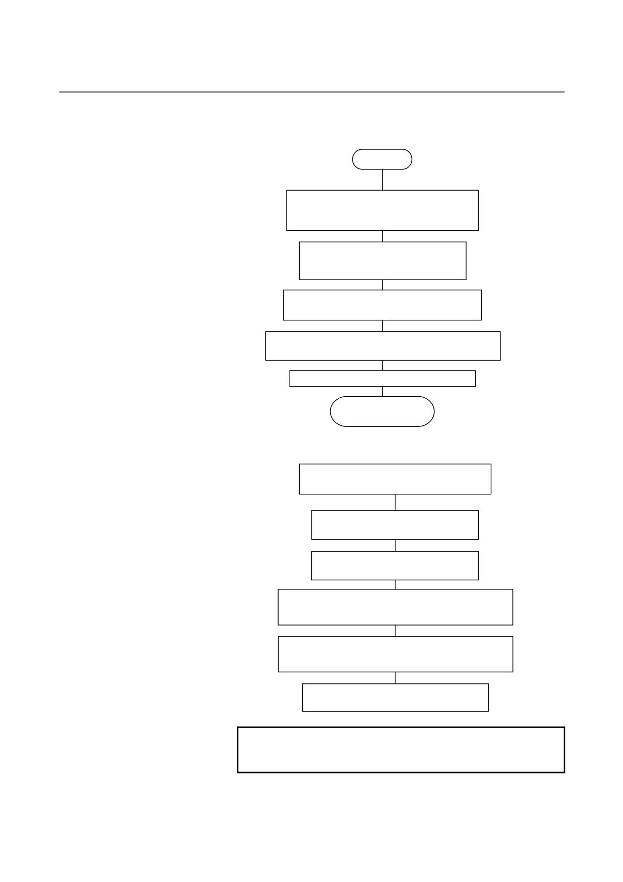
NOTE
If your machine is the PMC-N, NA, or QA, specify
6400.
0025 ⇒ 0019h. Because the upper byte is
exchanged with the lower byte, 1900h ⇒ 6400.
When CH2 data READY is "1", CH2
temperature data is sent to R012 to
R013.
When CH3 data READY is "1", CH3
temperature data is sent to R014 to
R015.
When CH4 data READY is "1", CH4
temperature data is sent to R016 to
R017.
- 162 -
B-61813E/04
CONNECTION
9.TEMPERATURE INPUT MODULE
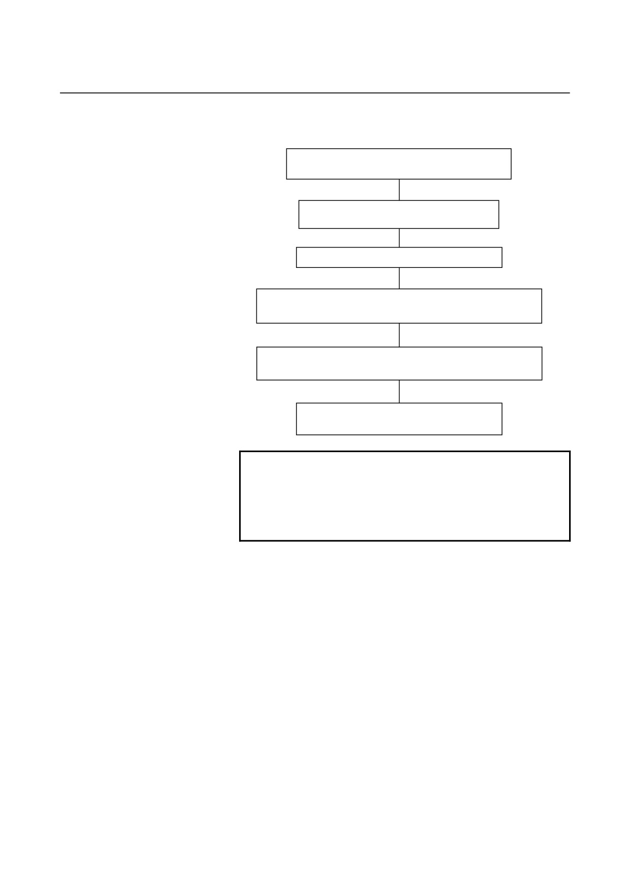
(3)
4-channel manual measurement mode
(a) Flowchart
START
* Check that NC READY
(DO16) and DO19 are "0".
Specify the module type (DO17).
0 : Thermocouple module
1 : Thermoresistance module
Specify the sensor type (DO18).
0 : Pt/K
1 : JPt/J
Set the number of channels bit (DO24) to
"1".
Set the 4-channel mode specification bit (DO25)
to "1".
Set NC READY (DO16) to "1".
Now ready to
measure.
* Reading CH1 and CH2 data
Ensure that the READ request bit
(DO22) is set to "0".
Reset the channel select bit
(DO26) to "0".
Set the READ request bit (DO22)
(Note)
to "1".
When CH1 data READY (DI14 of input signal) is
set to "1", input signals DI00 to DI12 represent
CH1 data.
When CH2 data READY (DI30 of input signal)
becomes "1", input signals DI16 to DI28
represent CH2 data.
Reset the READ request bit (DO22) to
"0".
NOTE
After setting NC READY to "1", wait for one second,
and then set the READ request to "1".
- 163 -
9.TEMPERATURE INPUT MODULE CONNECTION
B-61813E/04
* Reading CH3 and CH4 data
Ensure that the READ request bit (DO22) is set
to "0".
Reset the channel select bit (DO26) to
"0".
(Note)
Set the READ request bit (DO22) to "1".
When CH3 data READY (DI15 of input signal) is set to "1",
input signals DI00 to DI12 represent CH3 data.
When CH4 data READY (DI31 of input signal) is set to "1",
input signals DI16 to DI28 represent CH4 data.
Reset the READ request bit (DO22) to "0".
NOTE
1 After setting the NC READY bit to "1", wait for one
second, and then set the READ request bit to "1".
2 To create the ladder for 4-channel manual
measurement, refer to the above flowchart or timing
chart.
- 164 -
B-61813E/04
CONNECTION
9.TEMPERATURE INPUT MODULE
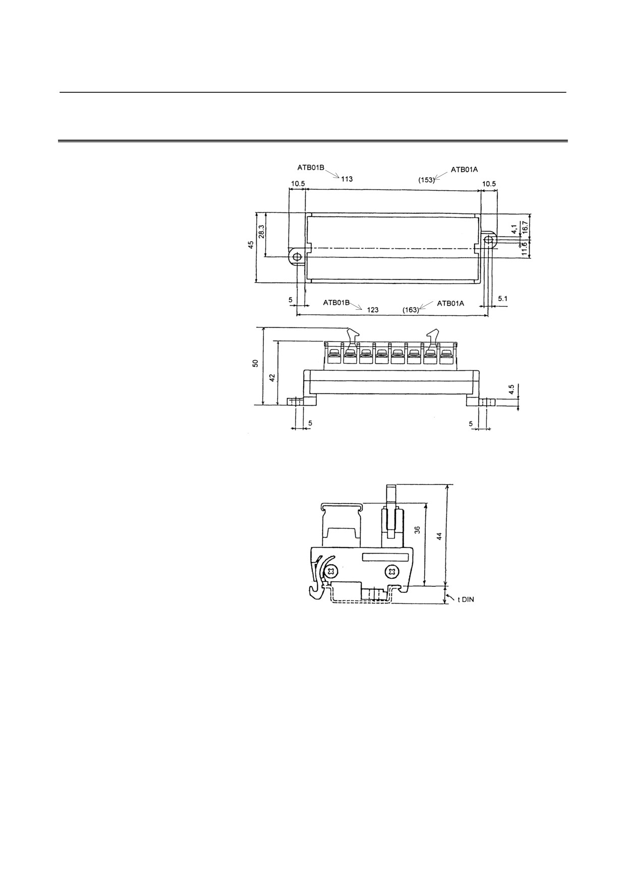
9.7
TERMINAL BOARD UNIT DIMENSIONS
(For thermocouple module) (For thermoresistance module)
Unit: mm
To use a DIN rail, add its height (tDIN) to the dimension shown below.
Unit: mm
- 165 -
10.OPTICAL I/O Link ADAPTER
CONNECTION
B-61813E/04
10
OPTICAL I/O Link ADAPTER
The signal cable K1X shown in the general connection diagram ( in
section 4.1) can be extended to the maximum length of 200 m with
optical fiber cables using an optical I/O link adapter.
Two optical I/O Link adapters, A13B-0154-B001 and
A13B-0154-B002 (high-speed response type).
NOTE
1 For the cable K2X, the optical I/O link adapter
cannot be applied to.
2 In the following cases, make sure to use an optical
fiber cable for K1X. For cabling within the same
cabinet, however, this applies only when the cable is
15 m or longer.
• When the cable is more than 10 meters long.
• When the cable K1X runs between different
cabinets and it is impossible to connect the
cabinets with a wire of 5.5 mm2 or thicker.
• When there is concern that the cable K1X is
influenced by strong noise.
For example;
When there is a strong electromagnetic noise
source beside the cable K1X such as a welding
machine and the like.
When a noise generating cable such as a power
cable and the like runs for a long distance in
parallel with the cable K1X.
- 166 -
B-61813E/04
CONNECTION
10.OPTICAL I/O Link ADAPTER
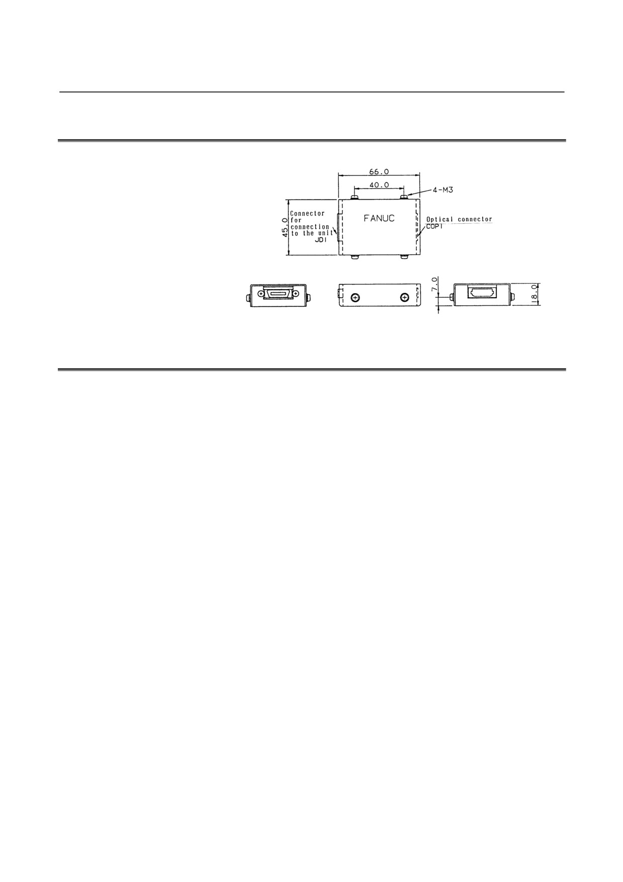
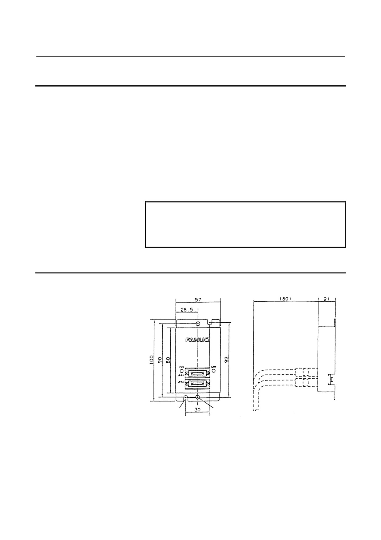
10.1 EXTERNAL DIMENSION OF OPTICAL I/O Link
Unit: mm
10.2 WEIGHT OF OPTICAL I/O Link
Main body: Approx. 100g
- 167 -
10.OPTICAL I/O Link ADAPTER
CONNECTION
B-61813E/04
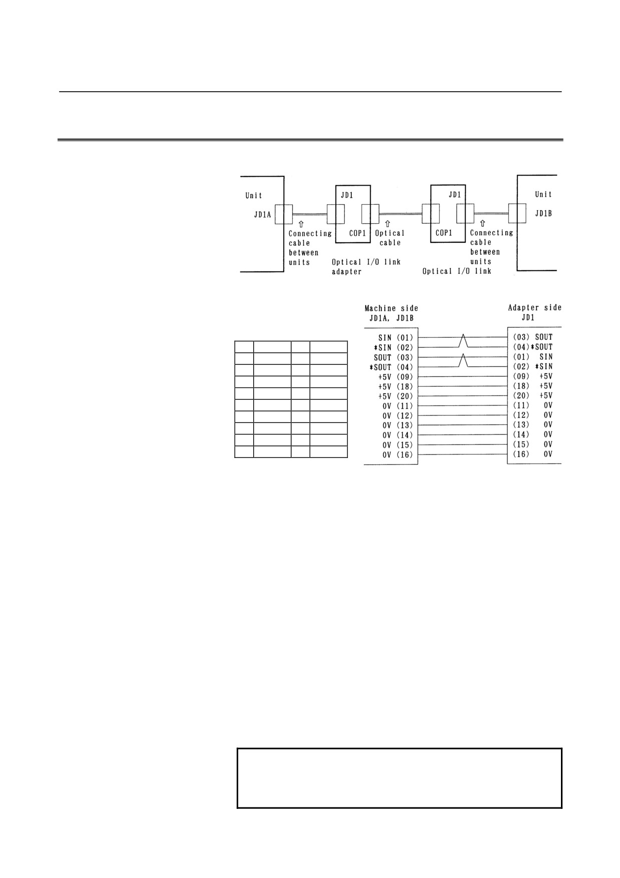
10.3 CONNECTION OF OPTICAL I/O Link
(1) Connection diagram
A66L-6001-0009
A66L-6001-0026
K3X
K3X
(2) Interunit connecting cables K3X
01
SIN
11
0V
02
*SIN
12
0V
03
SOUT
13
0V
04
*SOUT
14
0V
05
15
0V
06
16
0V
07
17
08
18
+5V
09
+5V
19
10
20
+5V
(a) Recommended connector for cable side:
PCR-E20FA (manufactured by HONDA TSUSHIN)
FI30-20S (manufactured by HIROSE ELECTRIC)
FCN-247J020-G/E (manufactured by Fujitsu)
52622-2011 (manufactured by Molex)
(b) Recommended cable (with material): A66L-0001-0284#10P
(c) Cable length: Max.2m (when the recommended cable is
used)
(3)
Optical cable
<1> Specification (Be sure to use the optical cable conforming to
this specification.):
• A66L-6001-0009 (usable only with the standard type
optical I/O Link adapter)
•
A66L-6001-0026
<2> Cable length:
Max.200m (when the standard type optical I/O Link adapter
A13B-0154-B001 is used)
Max.100m (when the high-speed response type optical I/O
Link adapter A13B-0154-B002 is used)
NOTE
The cable length stated above applies when the
optical fiber junction adapter A02B-0094-K841 is
not in use. See Subsection 10.7.5 for details.
- 168 -
B-61813E/04
CONNECTION
10.OPTICAL I/O Link ADAPTER
10.4 POWER SOURCE OF OPTICAL I/O Link ADAPTER
The power source is common to the standard type (A13B-0514-B001)
and the high-speed response type (A13B-0154-B002).
(1) Power voltage: 4.75 V to 5.25 V (at the receiving end)
(2) Consumption current: 200mA
(3) Power is supplied via the I/O Link cable K3X.
10.5 INSTALLATION CONDITIONS OF OPTICAL I/O Link
ADAPTER
(1) As this adapter is not a closed type, install it in the same closed
type cabinet as used for the NC control unit.
(2) Make sure to ground the case using the case fixing screw of the
adapter.
(3) As the adapter is light, it is not necessary to fix it with screws.
However, keep it from getting contact with other circuits lest it
should be short-circuited. In addition, when fixing the adapter in a
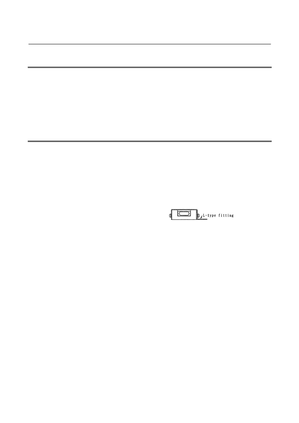
cabinet and the like, fix it with a L-type fitting using the case
fixing screws (M3) of the adapter.
- 169 -
10.OPTICAL I/O Link ADAPTER
CONNECTION
B-61813E/04
10.6
CAUTIONS FOR USING OPTICAL I/O Link ADAPTERS
10.6.1
Configuring I/O Links Using Optical I/O Link Adapters
The following restriction applies when I/O Links are configured using
optical I/O Link adapters.
Restriction on the number of optical I/O Link adapters used per I/O
Link channel
Master - Group#0 - - - - - - - - Group#1 - - - - • • • • • • - - - Group#15
(CNC) ↑ (I/O-A or the like) ↑ (I/O-A or the like) ↑ ↑ (I/O-A or the like)
Partition #1
Partition #2
Partition #3 Partition #4
When using the standard-type optical I/O Link adapter
(A13B-0154-B001):
Up to 5 partitions (I/O Link master -- group #0 -- group #1 -- ... --
group #15) can be configured with optical fibers.
Use electrical cables for the K1X in the other partitions.
When using the high-speed response type optical I/O Link adapter
(A13B-0154-B002):
The A13B-0154-B002 performs optical-electrical conversion
faster than the A13B-0154-B001.
All (16) partitions (master -- group #0 -- group #1 -- ... -- group
#15) can be configured with optical fiber.
NOTE
1 When using an optical fiber for I/O Links, use optical I/O Link adapters conforming to
the same specification on both ends of the optical fiber.
2 When using the high-speed response type optical I/O Link adapter
(A13B-0154-B002), do not use any optical fiber cable other than the
A66L-0001-0026.
When using the standard-type optical I/O Link adapter (A13B-0154-B001), either of
the optical fiber cables A66L-0001-0009 and A66L-0001-0026 can be used.
3 If 6 or more partitions of an I/O Link are configured with optical fibers, using the
standard-type optical I/O Link adapter even in one of these partitions disables the I/O
Link from operating normally.
When using optical fibers in 6 or more partitions, do not use the standard-type optical
I/O Link adapter; use only the high-speed response type optical I/O Link adapter.
Parts required per optical I/O Link partition
(1) When configuring 5 or fewer partitions with optical fibers
Two standard-type optical I/O Link adapters (A13B-0154-B001)
Two unit-to-unit connecting cables (K3X)
One optical cable (A66L-6001-0026 or A66L-6001-0009)
(2) When configuring six or more partitions with optical fibers
Two high-speed response type optical I/O Link adapters (A13B-0154-B002)
Two unit-to-unit connecting cables (K3X)
One optical cable (A66L-6001-0026)
- 170 -
B-61813E/04
CONNECTION
10.OPTICAL I/O Link ADAPTER
10.6.2
When Using Series 16i/18i/21i-MODEL B as Master
Two channels' worth of I/O Link signals are allocated to the I/O Link
connector (JD44A) of the Series 16i/18i/21i-MODEL B.
(1) When using only one I/O Link channel
No I/O Link connector adapter (A20B-1007-0680) is required.
Either an electrical cable or optical I/O Link can be used as the
K1X. When using the optical I/O Link, make a connection as
described in (1) of Section 10.3.
In this connection, the DI/DO data of channel 2 is invalid.
(2) When using two I/O Link channels
Using two I/O Link channels requires using the I/O Link
connector adapter (A20B-1007-0680).
When configuring an optical I/O Link, you can use optical fibers
between the I/O Link connector adapter and group #15 (all
partitions on channels 1 and 2). No optical fiber can be used
between the CNC (JD44A) and I/O Link connector adapter
(JD44B). Use a 1-meter electrical cable (A02B-0236-K848).
NOTE
Do not have the cable length from the CNC (JD44A)
to the I/O Link connector adapter and then to the
optical I/O Link adapter exceed 2 meters in total.
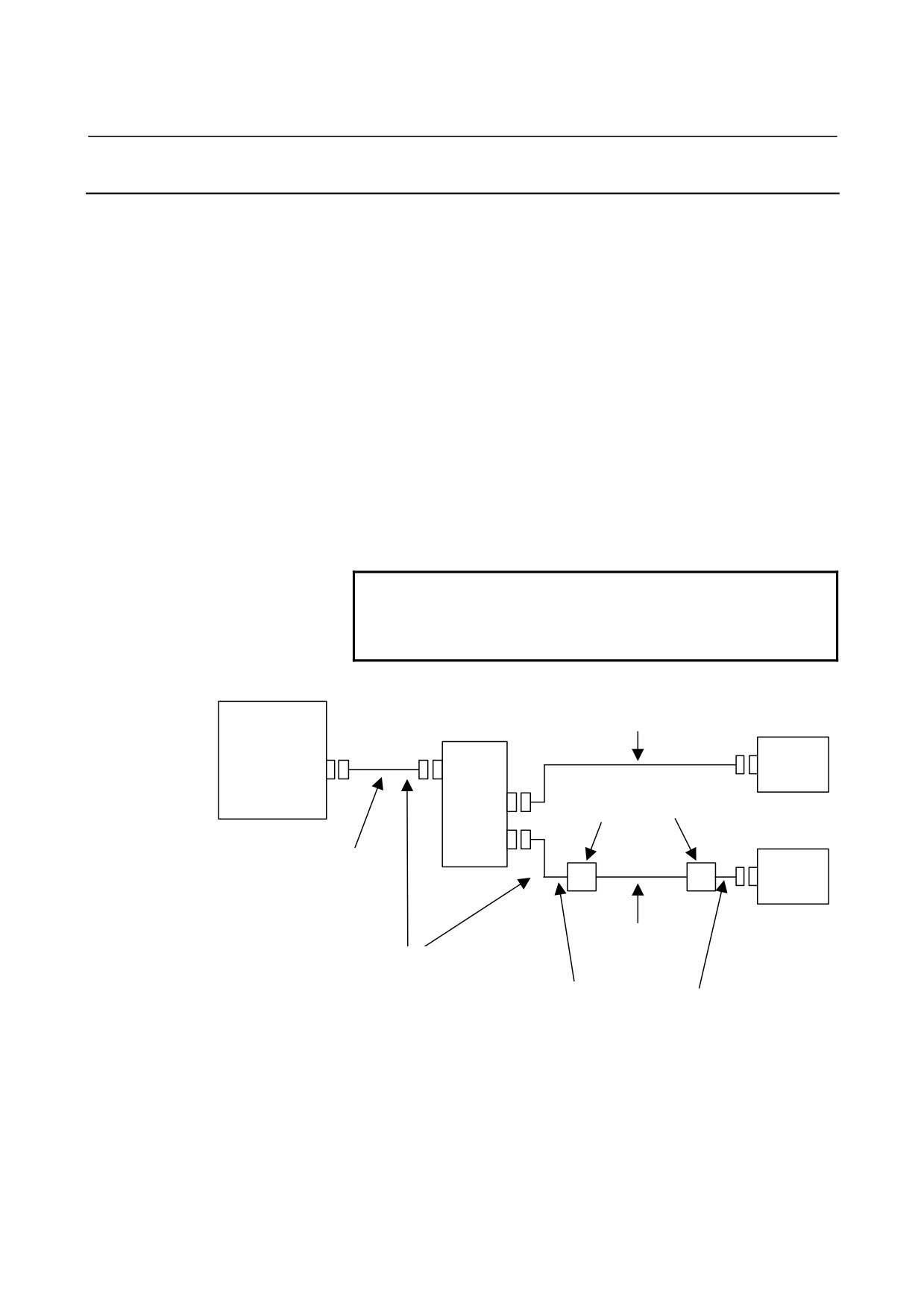
(Example) Partition #1 on channel 2 configured with optical I/O Link
CNC
Electrical cable K1X
Group#0
A20B-1007-0680
(16i/18i/21i
See (1) of Section 4.5.
I/O Unit, etc
-MODEL B)
Channel 1
JD1B
JD44A
JD44B
A13B-0154-B001 or
JD1A-1
A13B-0154-B002
Group#0
JD1A-2
I/O Unit, etc
A02B-0236-K848
(1m)
JD1B
Channel 2
Optical fiber
- A66L-6001-0009
- A66L-6001-0026
Keep the total cable length within 2 meters.
Electrical cable
See descriptions about unit-to-unit connecting cables K3X in Section 10.3.
- 171 -
10.OPTICAL I/O Link ADAPTER
CONNECTION
B-61813E/04
10.6.3
When Using Series 30i/31i/32i-MODEL B as Master
Three channels' worth of I/O Link signals are allocated to the I/O Link
connector (JD51A) of the Series 30i/31i/32i-MODEL B.
(1) When using only one I/O Link channel
You do not need to use the I/O Link connector adapter
(A20B-1007-0680) or
3-channel I/O Link connector adapter
(A20B-1008-0360).
Either an electrical cable or optical I/O Link can be used as the
K1X. When using the optical I/O Link, make a connection as
described in (1) of Section 10.3.
In this connection, the DI/DO data for channels 2 and 3 is invalid.
(2) When using two I/O Link channels
Using two I/O Link channels requires using the I/O Link
connector adapter (A20B-1007-0680).
When configuring an optical I/O Link, you can use optical fibers
between the I/O Link connector adapter and group #15 (all
partitions on channels 1 and 2). No optical fiber can be used
between the CNC (JD51A) and I/O Link connector adapter
(JD44B). Use a 1-meter electrical cable (A02B-0236-K848).
NOTE
Do not have the cable length from the CNC (JD51A)
to the I/O Link connector adapter and then to the
optical I/O Link adapter exceed 2 meters in total.
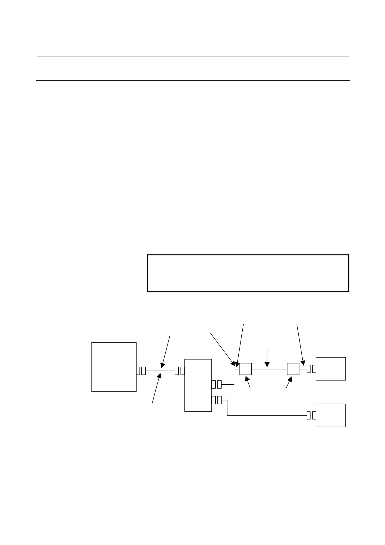
(Example) Partition #1 on channel 1 configured with optical I/O Link
Electrical cable
See descriptions about unit-to-unit connecting cables K3X in Section 10.3.
Keep the total cable length within 2 meters.
Optical fiber
- A66L-6001-0009
- A66L-6001-0026
Group#0
CNC
(30i/31i/32i)
I/O Unit, etc
JD1B
JD51A
JD44B
JD1A-1
Channel 1
A13B-0154-B001 or
Group#0
A13B-0154-B002
I/O Unit, etc
JD1A-2
A02B-0236-K848
Channel 2
(1m)
JD1B
A20B-1007-0680
Electrical cable K1X
See (1) of Section 4.5.
- 172 -
B-61813E/04
CONNECTION
10.OPTICAL I/O Link ADAPTER
(3) When using three I/O Link channels
Using three I/O Link channels requires using the 3-channel I/O
Link connector adapter (A20B-1008-0360).
When configuring an optical I/O Link, you can use optical fibers
between the I/O Link connector adapter and group #15 (all
partitions on channels 1, 2, and 3). No optical fiber can be used
between the CNC (JD51A) and I/O Link connector adapter
(JD51B). Use a 1-meter electrical cable (A02B-0303-K849).
NOTE
Do not have the cable length from the CNC (JD51A)
to the I/O Link connector adapter and then to the
optical I/O Link adapter exceed 2 meters in total.
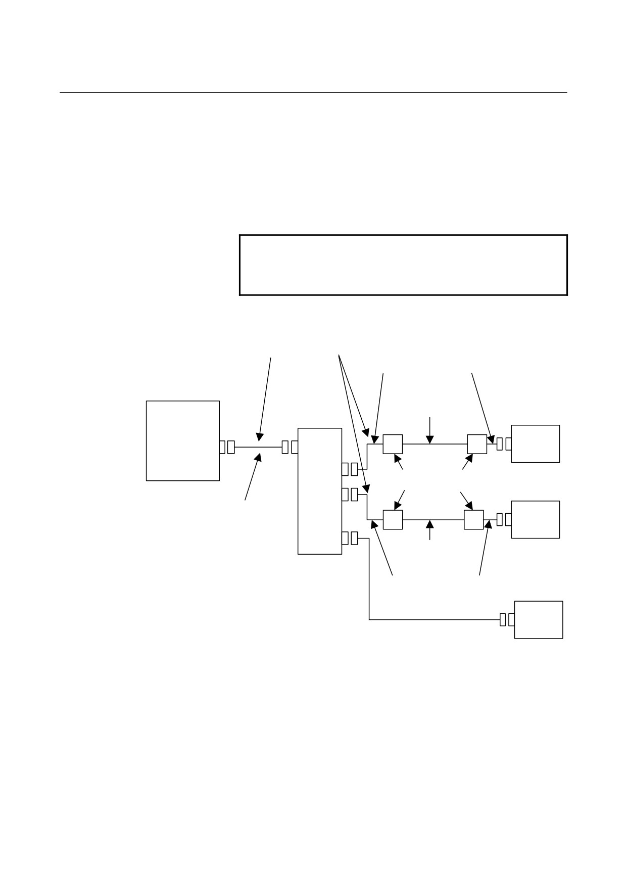
(Example) When configuring partition #1 on channels 1 and 2 with the
optical I/O Link
Electrical cable
Keep the total cable length within 2 meters.
See descriptions about unit-to-unit
connecting cables K3X in Section 10.3.
Optical fiber
- A66L-6001-0009
CNC
Group#0
- A66L-6001-0026
(30i/31i/32i)
I/O Unit, etc
Channel 1
JD1B
JD51A
JD51B
JD44A-1
A13B-0154-B001 or
A13B-0154-B002
Group#0
JD44A-2
I/O Unit, etc
A02B-0303-K849
Channel 2
(1m)
JD1B
JD1A
Optical fiber
- A66L-6001-0009
- A66L-6001-0026
A20B-1008-0360
Electrical cable
Group#0
See descriptions about unit-to-unit
I/O Unit, etc
connecting cables K3X in Section
10.3.
JD1B
Electrical cable K1X
Channel 3
See (1) of Section 4.5.
- 173 -
10.OPTICAL I/O Link ADAPTER
CONNECTION
B-61813E/04
10.7 OPTICAL FIBER CABLE
This CNC uses optical cables for connections between the control unit
and the I/O Unit. Unlike the conventional power cables, optical fiber
cables need special care in installation and handling. No optical fiber
cable can be used on movable parts.
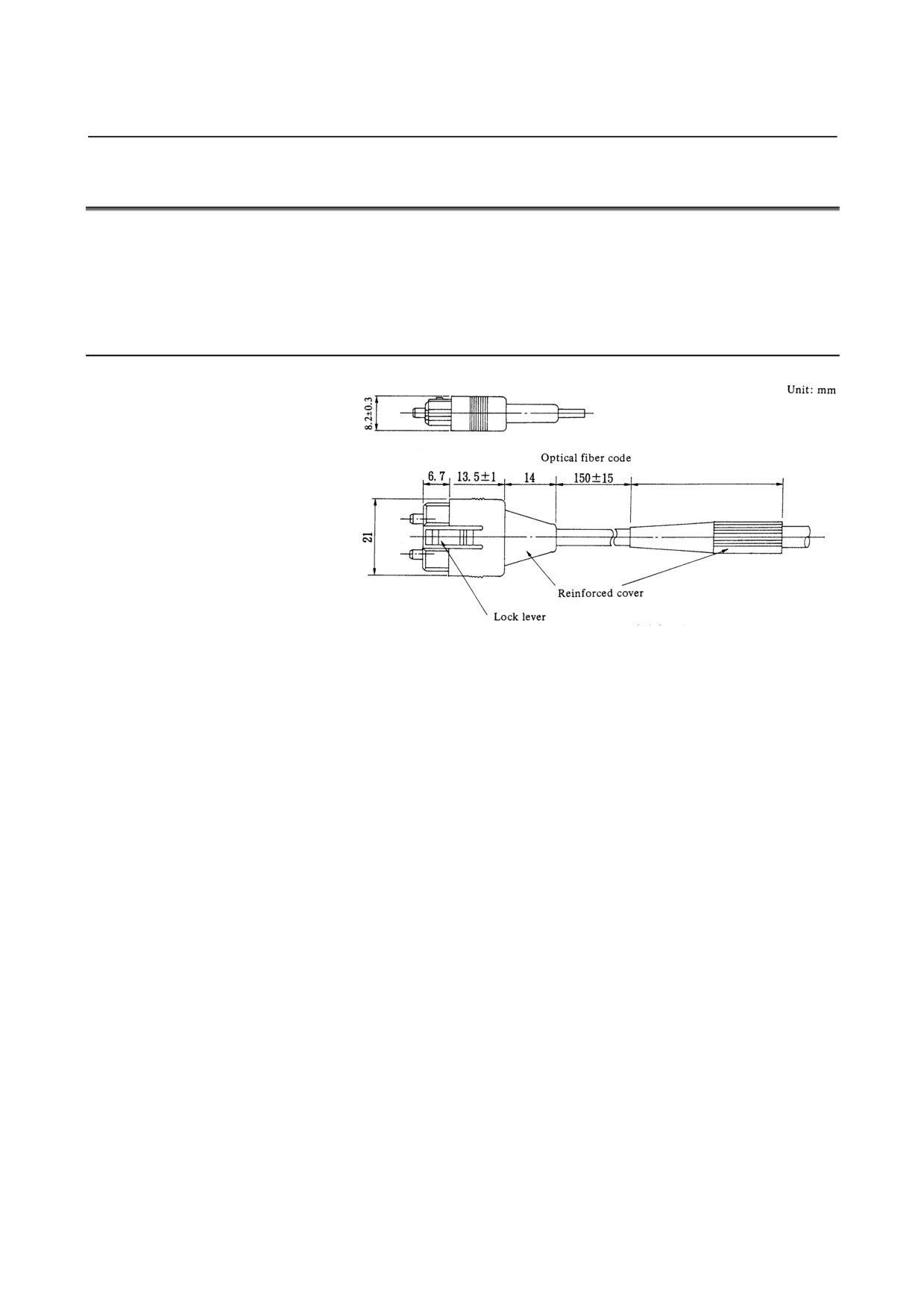
10.7.1 External View of Optical Fiber Cable
Reinforced optical fiber code diameter: 8.4mm
Tensile strength: Optical fiber code:
25kg
Optical fiber code-connector: 2kg
Reinforcing cover: 150kg
Bending radious of optical fiber code with reinforcing
cover: 50mm
(1) Standard length of an optical fiber cable is 10, 15, 20, 30, 50, 100,
and 200 meters.
(2) No machine tool builder is allowed to cut or joint optical fiber
cables.
(3) If it needs to relay on cabling, use optical fiber junction adapter.
Up to the relay points are allowed on a transmission line.
- 174 -
B-61813E/04
CONNECTION
10.OPTICAL I/O Link ADAPTER
10.7.2 Notice of Optical Fiber Cable Handling
(1) Even though reinforcing cover used on the optical fiber code has
enough mechanical strength, be sure not to be damaged by heavy
materials drop.
(2) Detaching and attaching of optical connector should always be
made by touching connector. Optical fiber code should not be
touched when replacement.
(3) Optical connector is automatically locked with upper side lock
levels after being connected. It is impossible to pull out the
connector without releasing the lock levers.
(4) Optical connector cannot be connected oppositely. Be sure the
connector direction when connection is done.
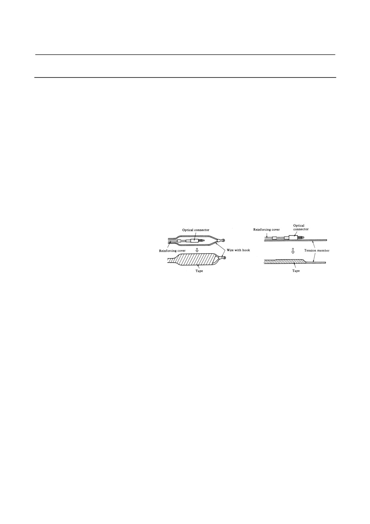
(5) Optical connector should be processed as follows before laying of
optical fiber cable.
Fix a reinforcing cover to a wire with hook or tension member by a
tape.
At laying hook the wire or pull the tension member taking enough
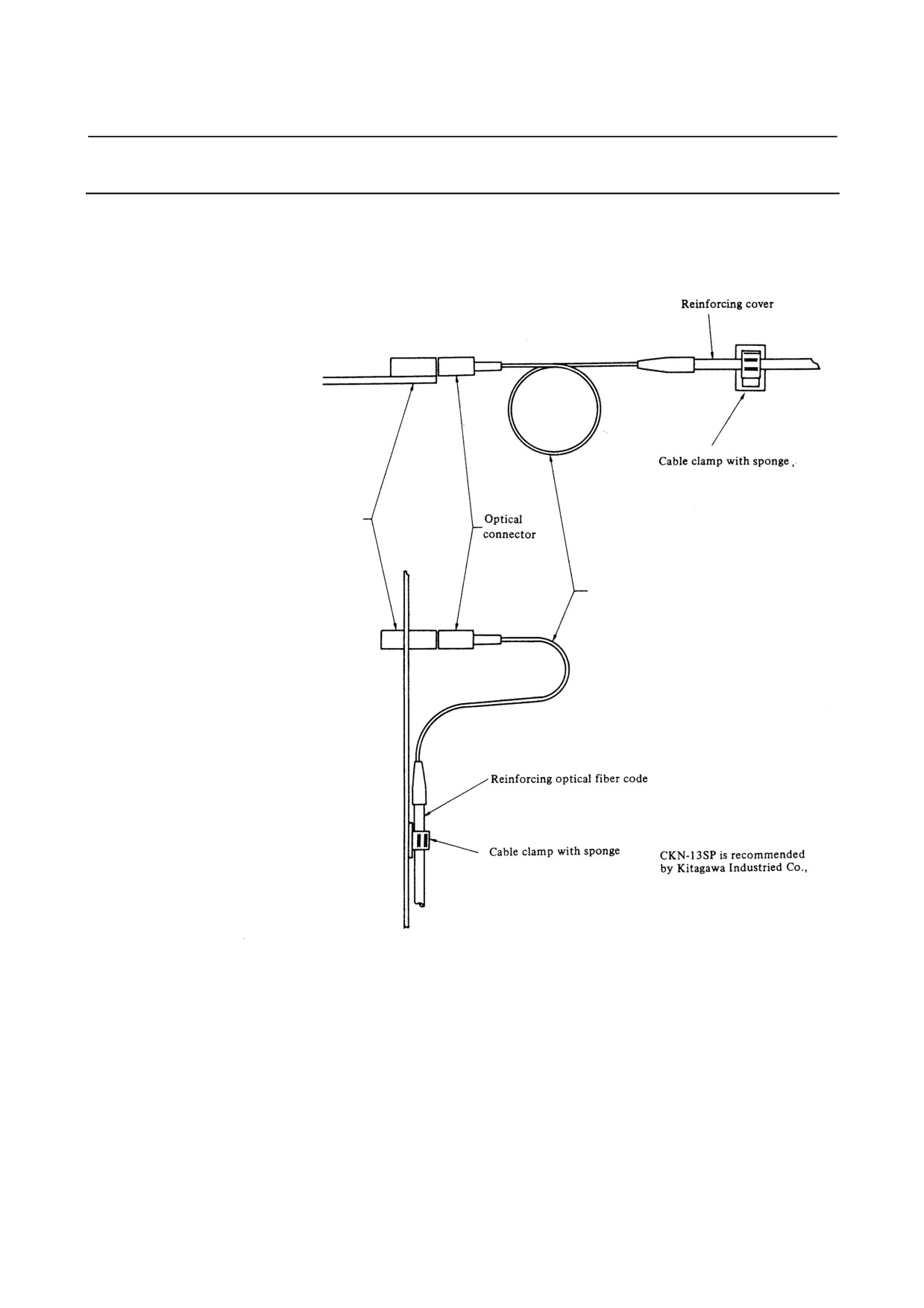
care that optical connector does not receive pulling strength.
(6) Reinforcing cover is fixed to cable lamp so that optical fiber cable
could not weigh directly the connecting part of connector.
(7) Notice that optical connector's chip is clear.
The attached protect cap must be always put on when optical
connector is not used.
Remove dirty with a clear tissue or absorbent cotton (cotton with
ethyl alcohol is applicable). No other organic solvent than ethyl
alcohol cannot be used.
- 175 -
10.OPTICAL I/O Link ADAPTER
CONNECTION
B-61813E/04
10.7.3 Optical Fiber Cable Clamping Method
When reinforcing cover is fixed at cable clamp with sponge, enough sag
at optical fiber code as shown below is necessary so that connecting part
of optical should not be weighed directly by optical fiber cable.
Optical fiber junction
adapter or optical data
link module
Optical fiber cable
(Bending radius should be more
than 25mm, and the reinforcing
sheath portion is 50 mm or longer.)
- 176 -
B-61813E/04
CONNECTION
10.OPTICAL I/O Link ADAPTER
10.7.4 Relay Using an Optical Fiber Junction Adapter
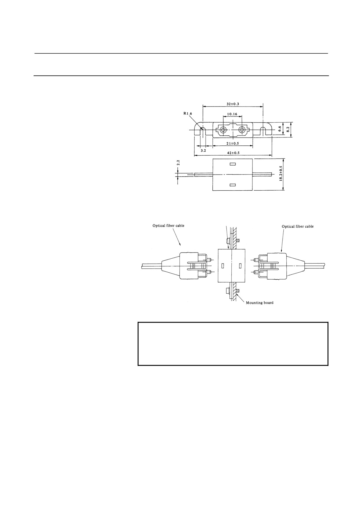
(1) External view of an optical fiber junction adapter
(2) Example of the use of an optical fiber junction adapter
Optical fiber junction adapter
Specification: A02B-0094-K841
NOTE
Up to one relay points are permitted.
When the high-speed response type optical I/O Link
adapter is used, however, it is impossible to use the
optical fiber junction adapter.
(3) Installing the optical fiber junction adapter
The optical fiber junction adapter should be installed within a cabinet,
as a rule. If it is impossible to avoid installing it within a cabinet, protect
the adapter and the optical cable portions (such as connectors and
cords) not covered with reinforcement coating from the outside air by,
for example, covering them with packing.
- 177 -
10.OPTICAL I/O Link ADAPTER
CONNECTION
B-61813E/04
(4) Environmental resistance of the optical fiber junction adapter
• The optical fiber junction adapter is not waterproof. Even when
optical cables are attached to both ends of the adapter, there are
very small gaps in the linked portions, so water resistance can not
be expected.
•
When optical cables are attached to both ends of the junction
adapter installed in a normal environment
(such as within a
cabinet), it is unlikely that dust will penetrate between the adapter
and optical fiber to the degree that it may hamper normal optical
linkage. If one or both ends of the adapter are left open, dust and
dirt may accumulate even when the adapter is in a normal
environment (such as within a cabinet). The dust and dirt on the
adapter ends is likely to hamper normal optical linkage when the
optical cables are attached. In such a case, clean the junction
adapter and the optical connector using the optical fiber junction
adapter cleaning method described below.
•
Do not allow cutting fluid to splash over the adapter or those
optical cable portions (such as connectors and cords) that are not
covered with reinforcement coating. If the inside of the adapter
and fiber end surfaces are contaminated with cutting fluid, a
malfunction may occur.
(3) Cleaning
If the optical fiber junction adapter, optical-to-electrical conversion
module, and optical cable are soiled, clean them according to the
following procedures.
• Cleaning the optical
fiber
junction
adapter
and
optical-to-electrical conversion module
First, clean the entire housing by wiping it with a cloth moistened
with, or by washing it in, ethyl alcohol or HCFC141B (alternative
CFC; High Shower spray can DS-2168, manufactured by Sun
Hayato). Similarly, wash the two sleeves in the adapter or wipe
them with a cotton swab or the like.
• Cleaning optical cables
For the optical cables, it is important to clean the connectors at
their ends. Any soiling on the optical fiber end surfaces will
hamper optical transmission, resulting in a malfunction. Wipe the
optical fiber end surfaces
(that is, the ferrule end surfaces)
thoroughly with a soft, clean cloth (like gauze) moistened with
ethyl alcohol or HCFC141B, in the same way as described above.
The use of cotton swabs may prove convenient. The fiber end
surfaces of low-loss optical cables are lower than the ferrules. To
remove any soiling from the fiber end surfaces completely, push
the cotton swab or gauze into the depressions all the way through
while rotating the ferrule. If the ferrules and optical connectors are
contaminated with oily substances, and they may extend over a
cleaned fiber end surface when it is attached to the
optical-to-electrical conversion module, it is a good idea to wash
them before wiping the optical fiber end surfaces, using the
procedure stated above.
- 178 -
B-61813E/04
CONNECTION
10.OPTICAL I/O Link ADAPTER
10.7.5 Maximum Transmission Distance by Optical Fiber Junction
Cable
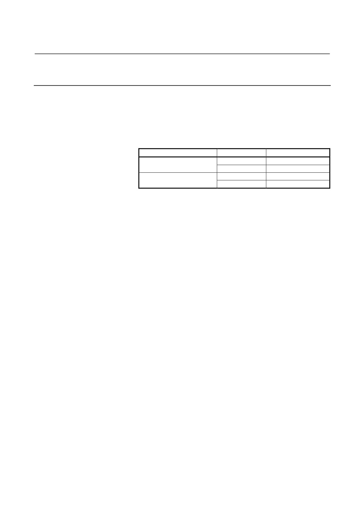
Maximum transmission distance by optical fiber junction cable is
shown below:
The maximum transmission distance varies depending on the number of
relay points supported by optical fiber junction adapters. When the
high-speed response type optical I/O Link adapter is in use, no optical
fiber junction adapter can be used.
Optical I/O Link adapter
Relay points
Max. trans. distance
0
200m
Standard type
1
100m (total)
0
100m
High-speed response type
1
Not applicable
- 179 -
B-61813E/04
CONNECTION
11.I/O Link DUMMY UNIT
11.1
OVERVIEW
If a slave unit (such as the FS0, Power Mate, I/O Unit-MODEL A, or
connection unit) is removed from the FANUC I/O Link (Note), the group
number for those that followed the removed slave unit changes. So, it
becomes necessary to change the PMC assignment. However,
connecting a FANUC I/O Link dummy unit in place of the removed
slave unit makes it unnecessary to change PMC assignment.
This chapter describes the electrical and structural specifications that
apply to the FANUC I/O Link dummy unit when it is connected to the
FANUC I/O Link.
Specification: A13B-0167-B001
NOTE
The FANUC I/O Link is a serial interface for
connecting the CNC or cell controller to the I/O
Unit-MODEL A, Power Mate, or other units for
high-speed transfer of I/O signals (bit data).
11.2
EXTERNAL DIMENSIONS
Units: mm
Mounting hole for 2-M5
Mounting hole for 2-M4
- 181 -

11.I/O Link DUMMY UNIT
CONNECTION
B-61813E/04
11.3
LED INDICATORS
(1) PWR: Lights when the FANUC I/O Link dummy unit is supplied
with power.
(2) LINK: Lights when the FANUC I/O Link is performing
communication.
11.4
WEIGHT
(1) Main unit:
Approximately 120 g
11.5
POWER REQUIREMENTS
(1) Supply voltage:
4.75 to 5.25 V (at reception terminal)
(2) Required current:
180 mA (maximum)
(3) Power dissipation:
0.9 W
(4) Supply method:
Via the I/O link cable
11.6
INSTALLATION CONDITIONS
This unit is not hermetically sealed. So, it must be installed in a cabinet
that is hermetically sealed to the same level as that for the NC. The
cabinet must be installed in a location where the following
environmental requirements are satisfied.
(1) Ambient temperature
Operating:
0 to 45°C
Storage and transportation:
-20 to 60°C
(2) Humidity
Normal:
75% or less (relative)
Short-period (within one month):
95% (maximum)
(3) Vibration
Operating:
0.5 G or less
- 182 -