FANUC I/O Unit-MODEL A. CONNECTION AND MAINTENANCE MANUAL (B-61813E/04) - page 2
B-61813E/04
CONNECTION
4.CONNECTION
4.6.3
Setting with the DIP Switch
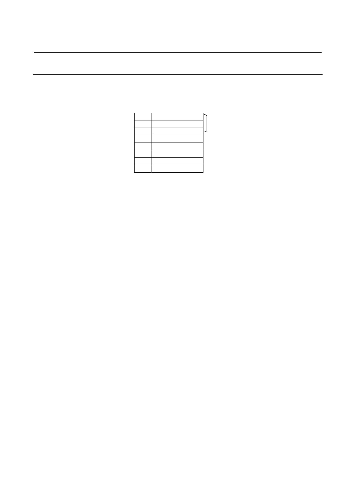
In the AIF02C, distributed link settings can be made with the DIP
switch on the back of the module.
The settings and corresponding signals are shown below.
1
2
Unused
3
4
EDSP
5
Q
6
H
7
URDY
8
R
(1)
EDSP (error display method selection)
Normally, set EDSP to the ON position.
(2)
Q and H (communication speed setting)
Normally, set both Q and H to the OFF positions.
(3)
URDY (setting of the power on/off information for the unit)
Normally, set URDY to the OFF position.
(4)
R (terminating resistor setting)
The ON position means that a terminating resistor must be
installed. The OFF position means that no terminating resistor
need be installed.
When only one communication cable is connected to the AIF02C,
terminate it and the basic unit at the end of the communication
cable with a resistor.
When two communication cables are connected to the AIF02C,
terminate the basic unit connected to the end of each
communication cable with a resistor. Do not connect a terminating
resistor to the AIF02C. (Refer to Section 4.6.2, "Connection.")
Refer to Section
5.1.1, "DIP switch setting," of the FANUC I/O
Unit-MODEL B CONNECTION MANUAL (B-62163E).
- 27 -
4.CONNECTION
CONNECTION
B-61813E/04
4.7
CONNECTING WITH I/O MODULES
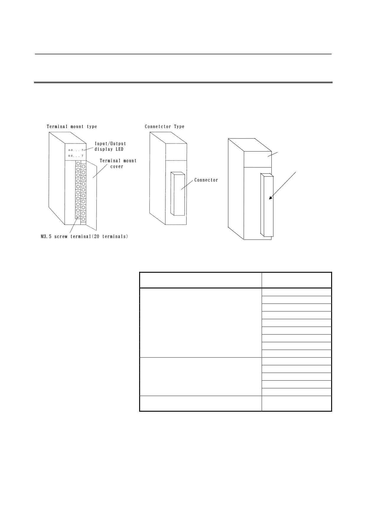
From the point of view of an external connecting method, there are two
types of I/O modules such as one with a terminal block and one with a
connector.
Terminal block manufactured by
Weidmüller (used in the AOD16D3)
Input/output
display LED
A 0 . . .
7
Specification of the terminal
B 0 . . .
7
block on the module
BL3.5//24/90F
The following three different connectors can be used on the
connector-type module.
Specification of the connector on the
Module name
module
AID32A1
AID32B1
AID32H1
AID32E1
Manufactured by HONDA TSUSHIN
AID32F1
MR-50RMA
AOD32A1
AOD32C1
AOD32D1
AIO40A
AID32E2
AID32F2
Manufactured by HIROSE ELECTRIC
AOD32C2
HIF3BB-50PA-2.54DS
AOD32D2
AOR16H2
Manufactured by HIROSE ELECTRIC
AOD16D2
HIF4-40P-3.18DS
- 28 -
B-61813E/04
CONNECTION
4.CONNECTION
(1)
Connect with each module following the connection diagrams of
Sections 4.2 and 5.3.
(2)
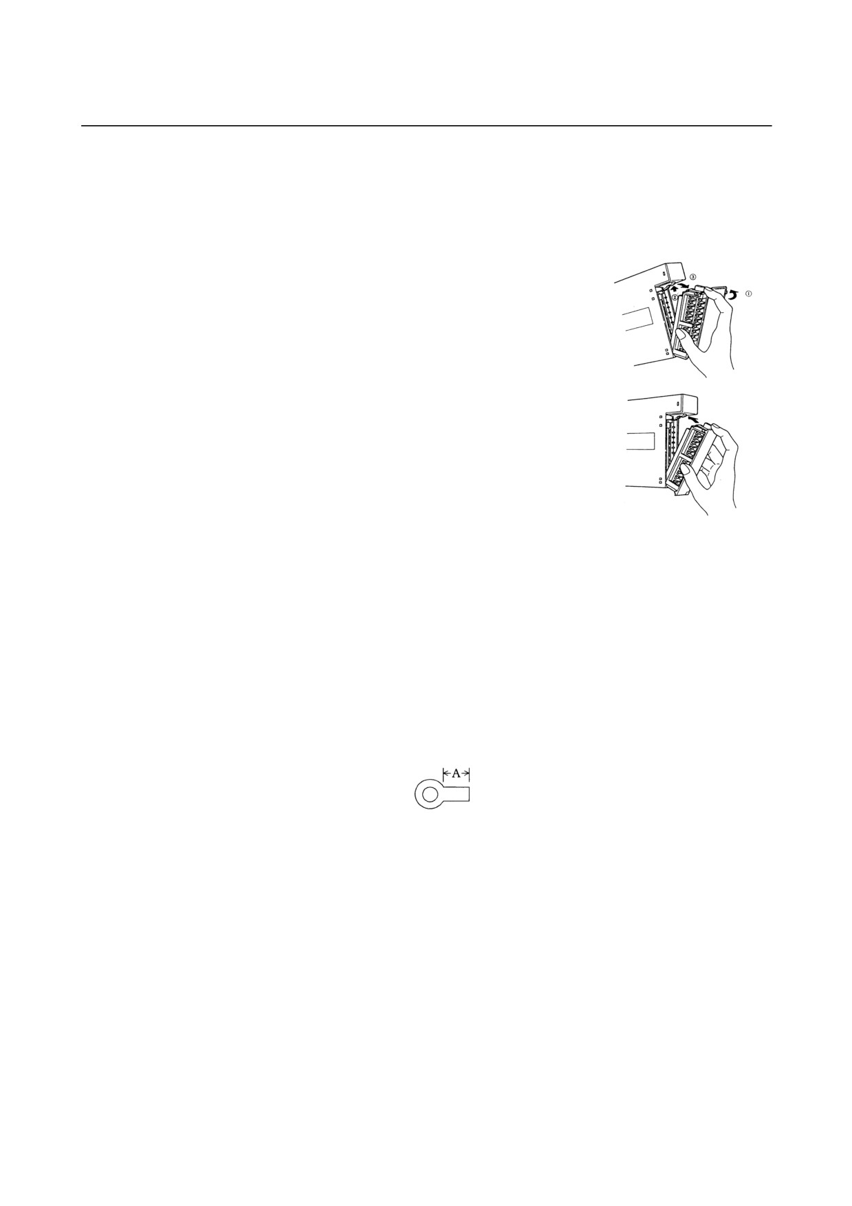
The terminal block is a removable type.
[Dismounting the terminal block]
<1> Open the cover of the terminal
block.
<2> Push up the latch at the top of the
terminal block.
<3> Drag out the tab at the top of the
terminal block and pull it out.
The terminal block will be
removed from the module.
[Mounting the terminal block]
<1> Insert the protruding portion at
the bottom of the terminal block
in the groove of the module
side.
<2> Push the terminal block using
the engaging point of the protruding portion and the groove
as an axis and mount it in the module firmly.
<3> Open the cover of the terminal block and check to make
sure the latch at the top of the terminal block is firmly set.
(3)
Cautionary points when wiring terminal block type
• Wiring material : AWG22 to 18 (0.3 to 0.75 mm2)
A wire as this as possible is recommended.
• Crimp style terminal : M3.5
Crimp style terminal with no
insulation sleeve and a short distance
"A", as illustrated in the drawing
below, is recommended.
DAIDO SOLDERLESS TERMINAL
1.25-S3.5
NICHIFU
1.25-3.5S etc.
•
Mark tube : Use a short mark tube as possible and cover
crimped part with the mark tube.
• Recommended tightening torque : 1 to 1.4 N⋅m
(4)
Wiring to the terminal block manufactured by Weidmüller
•
Wire with a cross section of 0.08 to 1.5 mm2 (VDE)/AWG28
to AWG14 (UL/CSA)
• Recommended tightening torque: 0.8 N⋅m
•
Size conformable when a ferrule (rod terminal) is used: 0.5 to
1.5 mm2
Peeling length: 6 mm
- 29 -
B-61813E/04
CONNECTION5.DIGITAL INPUT/OUTPUT MODULES
5.1
LIST OF MODULES
(1) Digital input modules
External
Input
Module
Rated
Rated
Polarity
Response time
Points
connection
LED display
type
name
voltage
current
*1
*2
Non-
AID32A1
24VDC
7.5mA
Both
Maximum 20msec
32
Connector A
Not provided
insulation
AID32B1
24VDC
7.5mA
Both
Maximum 2msec
32
Connector A
Not provided
type DC
Maximum 2msec
8
AID32H1
24VDC
7.5mA
Both
Connector A
Not provided
input
Maximum 20msec
24
AID16C
24VDC
7.5mA
NEG
Maximum 20msec
16
Terminal block
Provided
AID16K
24VDC
7.5mA
NEG
Maximum 2msec
16
Terminal block
Provided
AID16D
24VDC
7.5mA
POS
Maximum 20msec
16
Terminal block
Provided
Insulation
AID16L
24VDC
7.5mA
POS
Maximum 2msec
16
Terminal block
Provided
type DC
AID32E1
24VDC
7.5mA
Both
Maximum 20msec
32
Connector A
Not provided
input
AID32E2
24VDC
7.5mA
Both
Maximum 20msec
32
Connector B
Not provided
AID32F1
24VDC
7.5mA
Both
Maximum 2msec
32
Connector A
Not provided
AID32F2
24VDC
7.5mA
Both
Maximum 2msec
32
Connector B
Not provided
100 to
10.5mA
ON: Maximum 35msec
AC input
AIA16G
-
16
Terminal block
Provided
120VAC
(120VAC)
OFF: Maximum 45msec
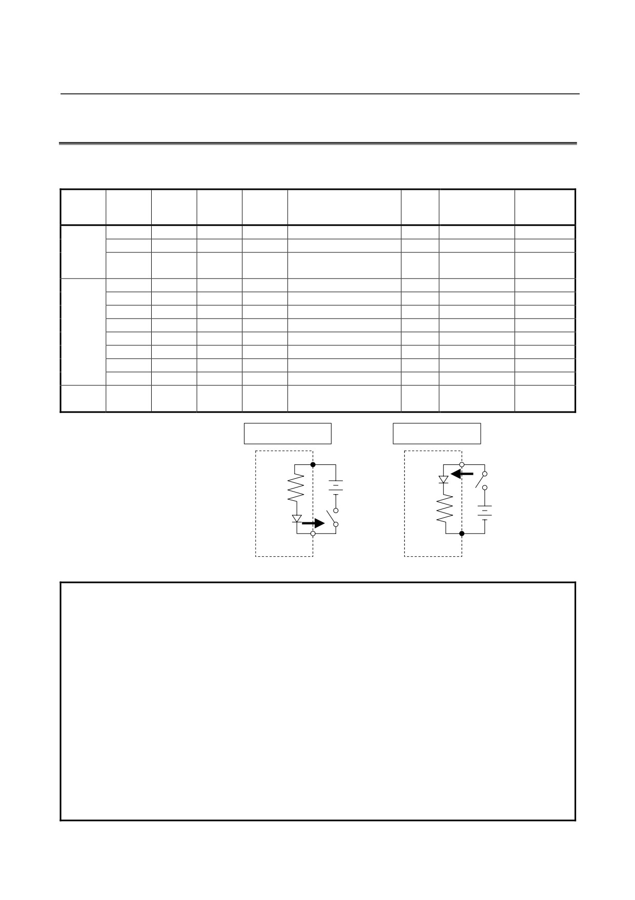
NEG circuit example
POS circuit example
Common pin
Input pin
+
Current
-
+
Current
-
Common pin
Input pin
Input module
Input module
NOTE
1 Polarity
NEGative : (Current source type, source type, or Nch)
Regard to be ON when input is at Low level.
POSitive : (Current sink type, sink type, or Pch)
Regard to be ON when input is High level.
2 Connectors (Section 5.4 shows a connector signal arrangement diagram as viewed
from the front of the module.)
Connector A : HONDA TSUSHIN MR-50RMA connector
It is recommended that the MR-50LW (housing) and MR50-FH
(soldering-type connector) or MRP-50F01 (crimp connector) +
MRP-F112 (contact) be used on the cable.
Connector B : HIROSE ELECTRIC HIF3BB-50PA-2.54DS
It is recommended that the HIF3BB-50D-2.54R (press-mount
connector) be used on the cable.
3 For the details of the specifications for each module, refer to the section 5.3.
- 31 -
5.DIGITAL INPUT/OUTPUT MODULESCONNECTION
B-61813E/04
(2) Digital output modules
External
Rated
Maximum
Polarity
Points/
LED
Output
Output type
Module name
Points
connection
voltage
current
*1
common
display
protection
*2
Non-insulation
Not
AOD32A1
5 to 24VDC
0.3A
NEG
32
8
Connector A
Not provided
type DC output
provided
AOD08C
2A
NEG
8
8
Terminal block
Provided
Fuse
AOD08D
2A
POS
8
8
Terminal block
Provided
Fuse
Output
AOD08DP
2A
POS
8
8
Terminal block
Provided
protection
device
AOD16C
0.5A
NEG
16
8
Terminal block
Provided
Not provided
AOD16D
0.5A
POS
16
8
Terminal block
Provided
Not provided
AOD16D2
2A
POS
16
4
Connector C
Provided
Not provided
Terminal block
Insulation type
AOD16D3
2A
POS
16
4
Provided
Fuse
B
12 to 4VDC
DC output
Output
AOD16DP
0.3A
POS
16
8
Terminal block
Provided
protection
device
Not
AOD32C1
0.3A
NEG
32
8
Connector A
Not provided
provided
Not
AOD32C2
0.3A
NEG
32
8
Connector B
Not provided
provided
Not
AOD32D1
0.3A
POS
32
8
Connector A
Not provided
provided
Not
AOD32D2
0.3A
POS
32
8
Connector B
Not provided
provided
AOA05E
100 to
2A
-
5
1
Terminal block
Provided
Fuse
240VAC
AC output
AOA08E
1A
-
8
4
Terminal block
Provided
Fuse
100 to
AOA12F
0.5A
-
12
6
Terminal block
Provided
Fuse
120VAC
Maximum
AOR08G
4A
-
8
1
Terminal block
Provided
Not provided
250VAC /
RELAY output
AOR16G
30VDC
2A
-
16
4
Terminal block
Provided
Not provided
AOR16H2
30VDC
2A
-
16
4
Connector B
Provided
Not provided
(3) Digital input/output hybrid module
External
Input/output
Rated
Polarity
Points/
LED
Output
Module name
Specification
Points
connection
type
voltage
*1
common
display
protection
*2
Current rating:
7.5 mA
Non-insulation
24VDC
Response
Both
24
24
type DC input
time: 20 ms
Connector A
Not
AIO40A
(maximum)
(shared by input
Not provided
provided
Maximum
and output signals)
Non-insulation
current:
24VDC
NEG
16
16
type DC output
0.2 A/point and
2A for common
- 32 -
B-61813E/04
CONNECTION5.DIGITAL INPUT/OUTPUT MODULES
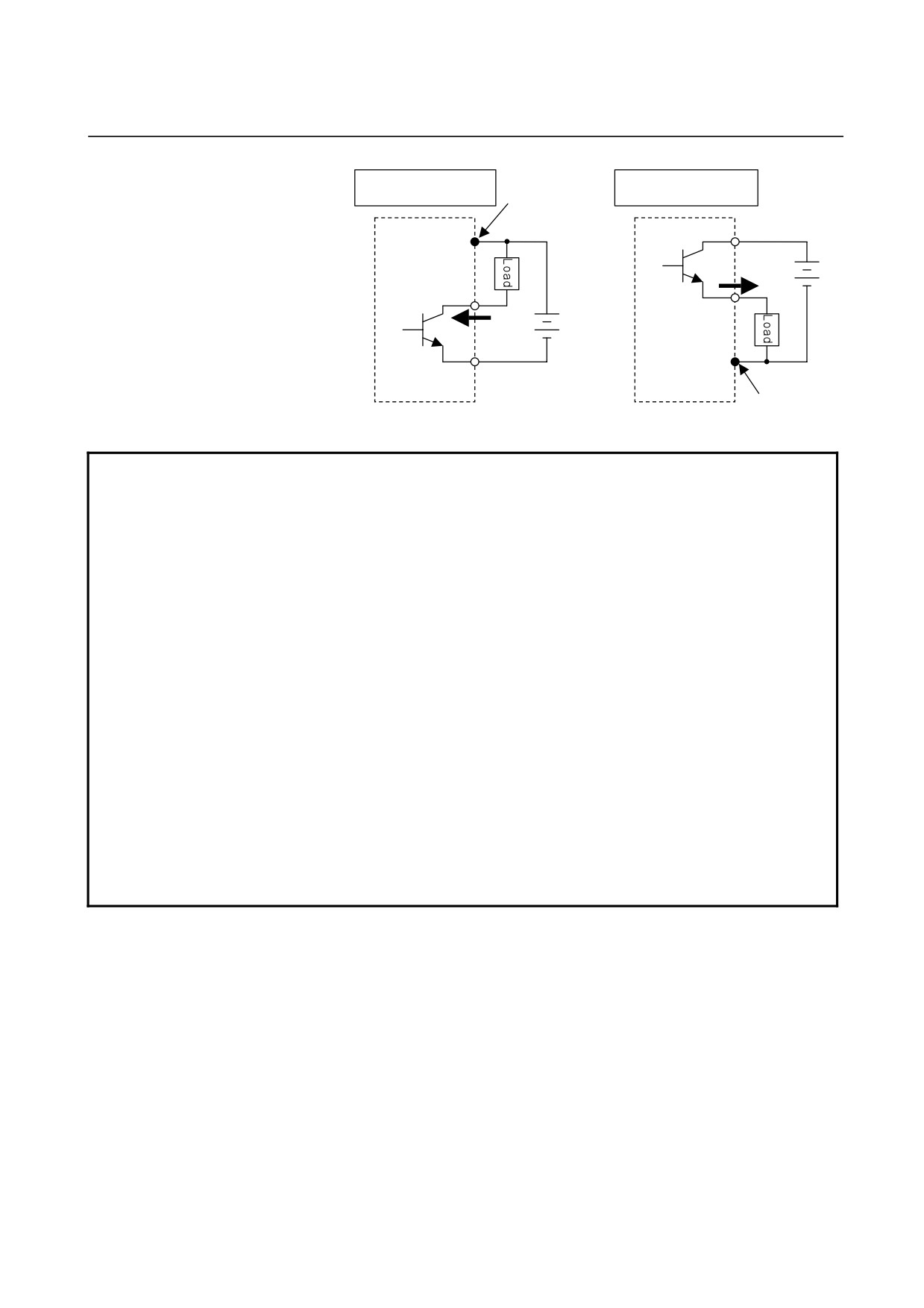
NEG circuit example
POS circuit example
Common pin
+24V
+24V
+
Current
Output pin
+
-
Output pin
Current
-
0V
0V
Common pin
Output module
Output module
NOTE
1 Polarity
NEGative : (Current sink type)
Output is at Low level when ON.
POSitive : (Current source type)
Output is at High level when ON.
2 Connector and terminal block B
(Section 5.4 shows a connector signal arrangement diagram as viewed from the front
of the module.)
Connector A
: HONDA TSUSHIN MR-50RMA connector
It is recommended that the MR-50LW (housing) and MR50-FH
(soldering-type connector) or MRP-50F01 (crimp connector) +
MRP-F112 (contact) be used on the cable.
Connector B
: HIROSE ELECTRIC HIF3BB-50PA-2.54DS
It is recommended that the HIF3BB-50D-2.54R (press-mount
connector) be used on the cable.
Connector C
: HIROSE ELECTRIC HIF4-40P-3.18DS
It is recommended that the HIF4-40D-3.18R (press-mount
connector) be used on the cable.
Terminal block B : Weidmüller BL3.5/24/90F
The terminal block for the cable comes with the module.
3 For the details of the specifications for each module, refer to the section 5.3.
4 The maximum current of the DC output module includes the permissible rush current.
- 33 -
5.DIGITAL INPUT/OUTPUT MODULESCONNECTION
B-61813E/04
5.2
CORRESPONDENCE BETWEEN I/O SIGNALS AND
ADDRESSES IN A MODULE
The term "address in a module" refers to an address allocated within
each DI/DO module and relative to the start address (Xm, Yn) of the
module.
5.2.1
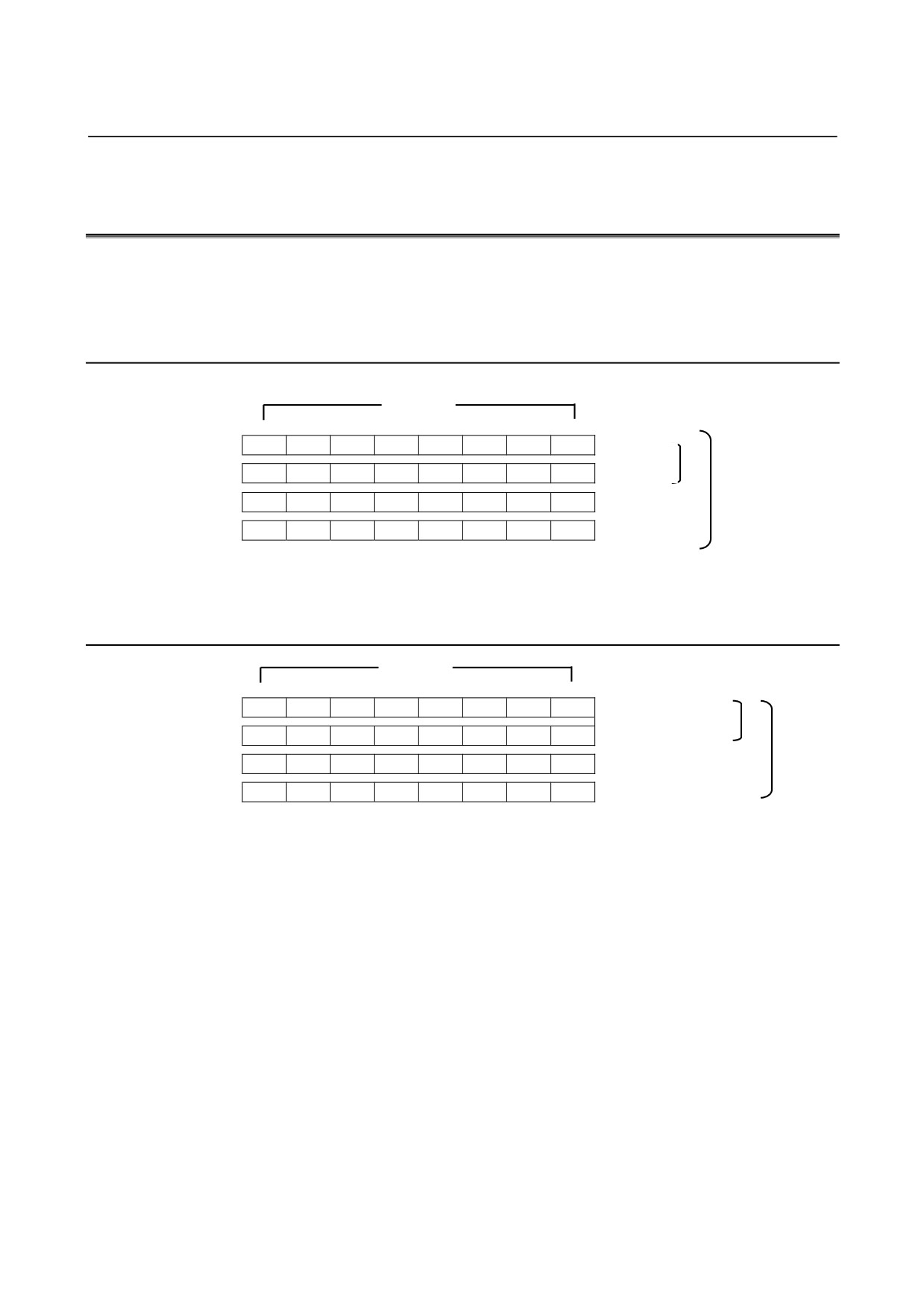
Module with 16/32 Digital Inputs (DI)
Input bits
Address in the
7
6
5
4
3
2
1
0
module
Xm
A7
A6
A5
A4
A3
A2
A1
A0
DI module of
Xm+1
B7
B6
B5
B4
B3
B2
B1
B0
16 points
DI module of
Xm+2
C7
C6
C5
C4
C3
C2
C1
C0
32 points
Xm+3
D7
D6
D5
D4
D3
D2
D1
D0
When a contact connected to an input of an input module is closed, the
corresponding input signal becomes "1".
5.2.2
Module with 5/8/12/16/32 Digital Outputs (DO)
Output bits
Address in the
DO module of 5
7
6
5
4
3
2
1
0
module
and 8 points
Yn
A7
A6
A5
A4
A3
A2
A1
A0
DO module of 12
Yn+1
B7
B6
B5
B4
B3
B2
B1
B0
and 16 points
Yn+2
C7
C6
C5
C4
C3
C2
C1
C0
DO module of
Yn+3
D7
D6
D5
D4
D3
D2
D1
D0
32 points
When the output signal from an output module is "1", the corresponding
output contact (or transistor) is closed.
- 34 -
B-61813E/04
CONNECTION5.DIGITAL INPUT/OUTPUT MODULES
5.2.3
AIO40A Module (Hybrid Module with 24 Input and 16 Output
Points)
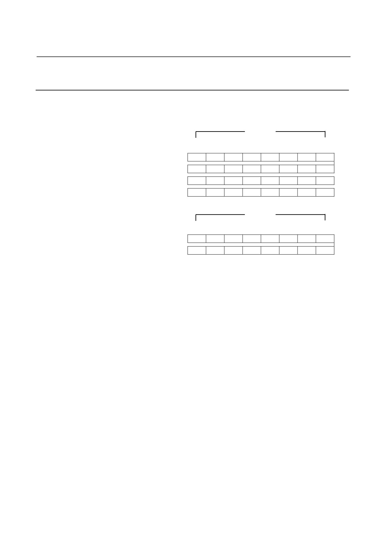
The allotment of this module requires 4 input and 2 output bytes.
Input byte 4 (Xm + 3) is invalid.
Input section
Input bits
Address in the
7
6
5
4
3
2
1
0
module
Xm
A7
A6
A5
A4
A3
A2
A1
A0
Xm+1
B7
B6
B5
B4
B3
B2
B1
B0
Xm+2
C7
C6
C5
C4
C3
C2
C1
C0
Xm+3
-
-
-
-
-
-
-
-
Output section
Output bits
Address in the
7
6
5
4
3
2
1
0
module
Yn
D7
D6
D5
D4
D3
D2
D1
D0
Yn+1
E7
E6
E5
E4
E3
E2
E1
E0
- 35 -
5.DIGITAL INPUT/OUTPUT MODULESCONNECTION
B-61813E/04
5.3
SPECIFICATION FOR EACH MODULE
Specifications for the module are shown in the following pages.
(1)
Input module
AID32A1
(2)
Input module
AID32B1
(3)
Input module
AID32H1
(4)
Input module
AID16C
(5)
Input module
AID16K
(6)
Input module
AID16D
(7)
Input module
AID16L
(8)
Input module
AID32E1
(9)
Input module
AID32E2
(10)
Input module
AID32F1
(11)
Input module
AID32F2
(12)
Input module
AIA16G
(13)
Output module
AOD32A1
(14)
Output module
AOD08C
(15)
Output module
AOD08D
(16)
Output module
AOD08DP
(17)
Output module
AOD16C
(18)
Output module
AOD16D
(19)
Output module
AOD16D2
(20)
Output module
AOD16D3
(21)
Output module
AOD16DP
(22)
Output module
AOD32C1
(23)
Output module
AOD32C2
(24)
Output module
AOD32D1
(25)
Output module
AOD32D2
(26)
Output module
AOA05E
(27)
Output module
AOA08E
(28)
Output module
AOA12F
(29)
Output module
AOR08G
(30)
Output module
AOR16G
(31)
Output module
AOR16H2
(32)
Input/output module
AIO40A
- 36 -
B-61813E/04
CONNECTION5.DIGITAL INPUT/OUTPUT MODULES
(1) Input module AID32A1 (Non-insulation type)
Item
Specifications
Points/module
32 points
Points/common
16 points/common
Sink/source current
Both directions
Input voltage
24VDC +10%, −20%
Input current
7.5mA (average)
ON voltage, current
Min. 18VDC, min. 6mA
OFF voltage, current
Max. 6VDC, max. 1.5mA
Response time
OFF→ON
Max.20ms
This is the value from input to output in the module. The actual value is
ON→OFF
Max.20ms
determined by adding it to the scanning time depending on each
system.
Input display
Not provided
External connection
Connector (HONDA TSUSHIN MR-50RMA)
Terminal connection and
circuitry
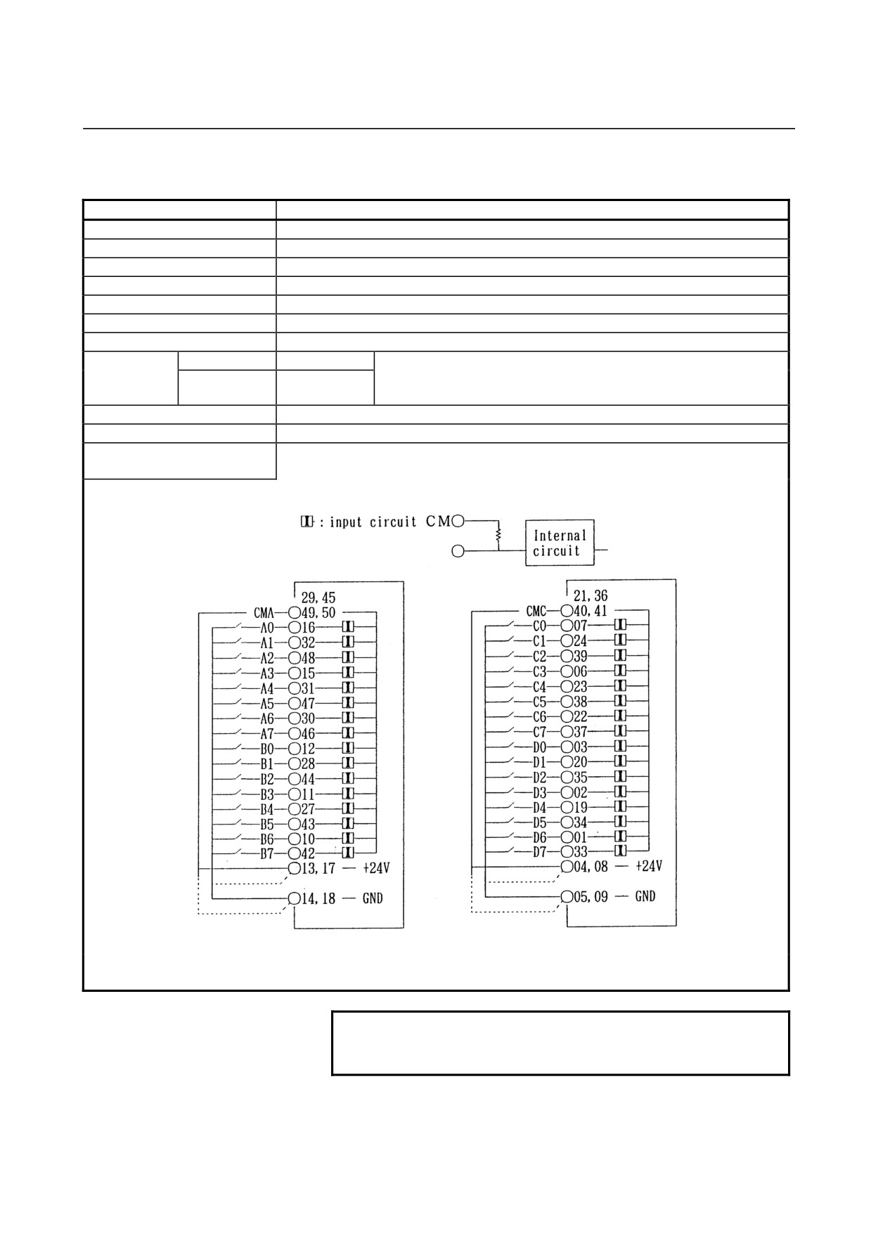
+24V or GND can be selected for input common as above fig.
NOTE
1 Make sure to connect all common (CMA, CMC) pins.
2 This module outputs +24 V on pins 13, 17, 04, and 08.
- 37 -
5.DIGITAL INPUT/OUTPUT MODULESCONNECTION
B-61813E/04
(2) Input module AID32B1 (Non-insulation type)
Item
Specifications
Points/module
32 points
Points/common
16 points/common
Sink/source current
Both directions
Input voltage
24VDC +10%, −20%
Input current
7.5mA (average)
ON voltage, current
Min. 18VDC, min. 6mA
OFF voltage, current
Max. 6VDC, max. 1.5mA
Response time
OFF→ON
Max.2ms
This is the value from input to output in the module. The actual value is
ON→OFF
Max.2ms
determined by adding it to the scanning time depending on each
system.
Input display
Not provided
External connection
Connector (HONDA TSUSHIN MR-50RMA)
Terminal connection and
circuitry
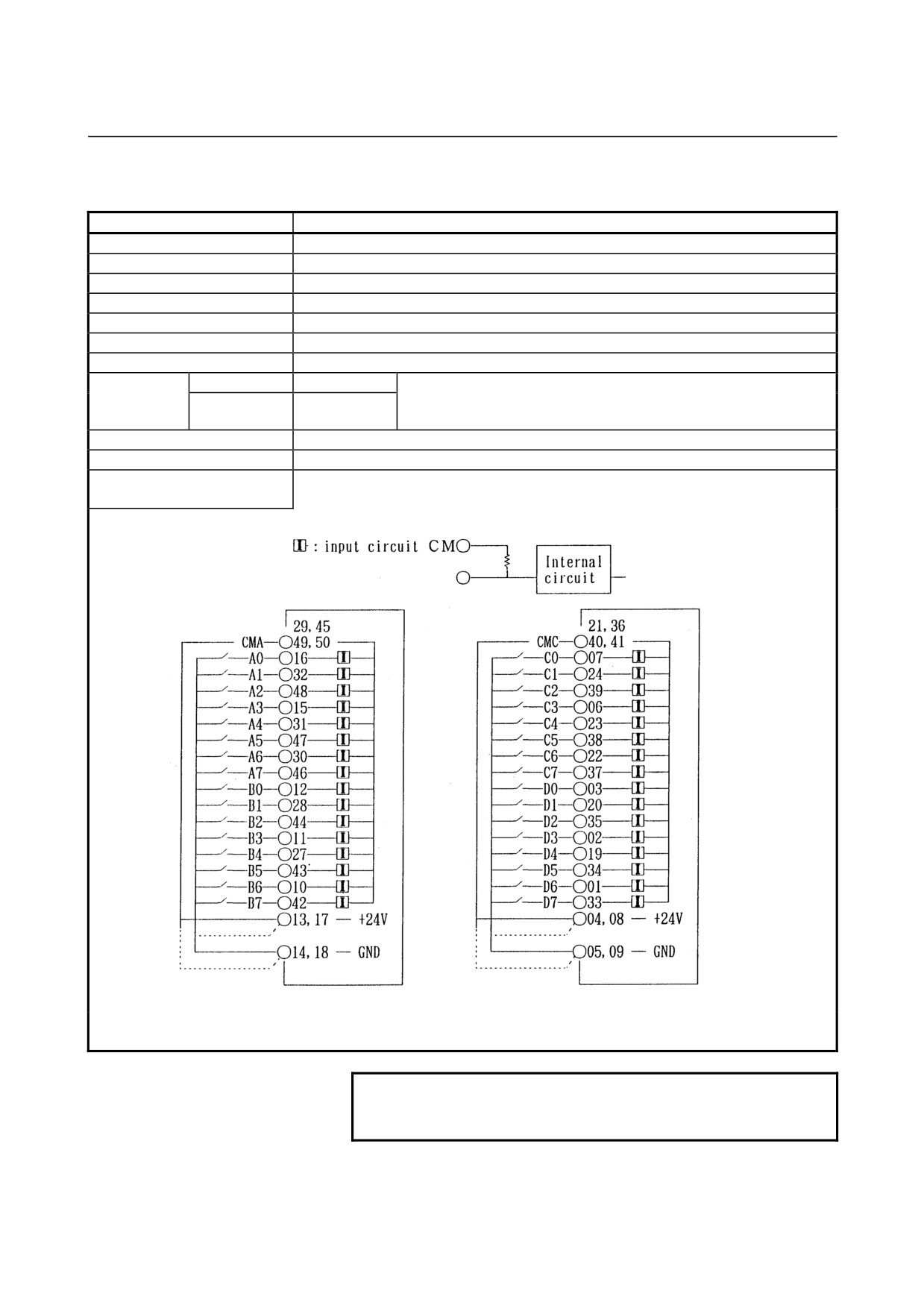
+24V or GND can be selected for input common as above fig.
NOTE
1 Make sure to connect all common (CMA, CMC) pins.
2 This module outputs +24 V on pins 13, 17, 04, and 08.
- 38 -
B-61813E/04
CONNECTION5.DIGITAL INPUT/OUTPUT MODULES
(3) Input module AID32H1
Item
Specifications
Points/module
32 points
Points/common
16 points/common
Sink/source current
Both directions
Input voltage
24VDC +10%, −20%
Input current
7.5mA (average)
ON voltage, current
Min. 18VDC, min. 6mA
OFF voltage, current
Max. 6VDC, max. 1.5mA
Response time
OFF→ON
Max.2ms (A0 to A7)
This is the value from input to output in the module. The actual
Max.20ms (B0 to D7)
value is determined by adding it to the scanning time depending
ON→OFF
Max.2ms (A0 to A7)
on each system.
Max.20ms (B0 to D7)
Input display
Not provided
External connection
Connector (HONDA TSUSHIN MR-50RMA)
Terminal connection and
circuitry
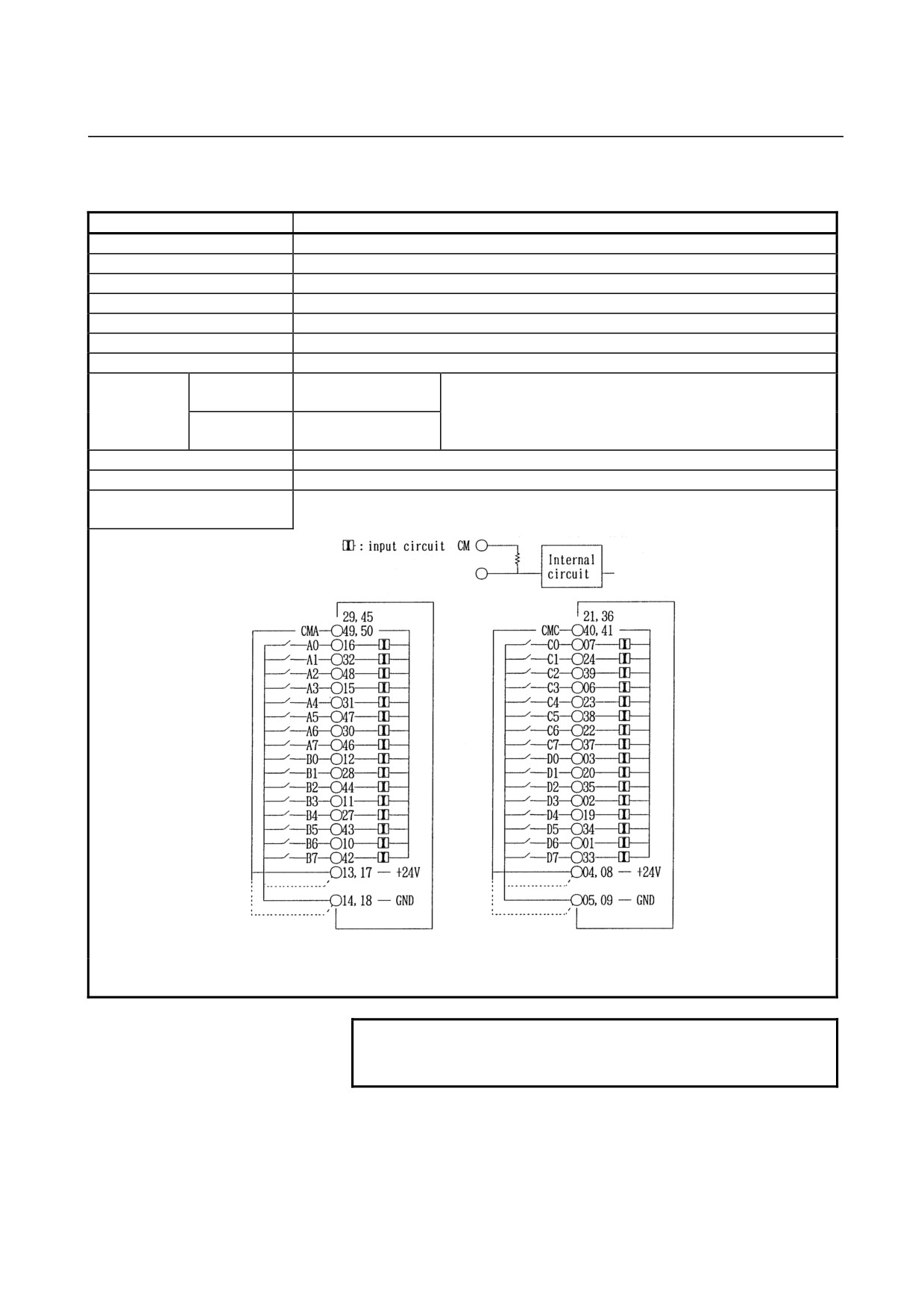
+24V or GND can be selected for input common as above fig.
NOTE
1 Make sure to connect all common (CMA, CMC) pins.
2 This module outputs +24 V on pins 13, 17, 04, and 08.
- 39 -
5.DIGITAL INPUT/OUTPUT MODULESCONNECTION
B-61813E/04
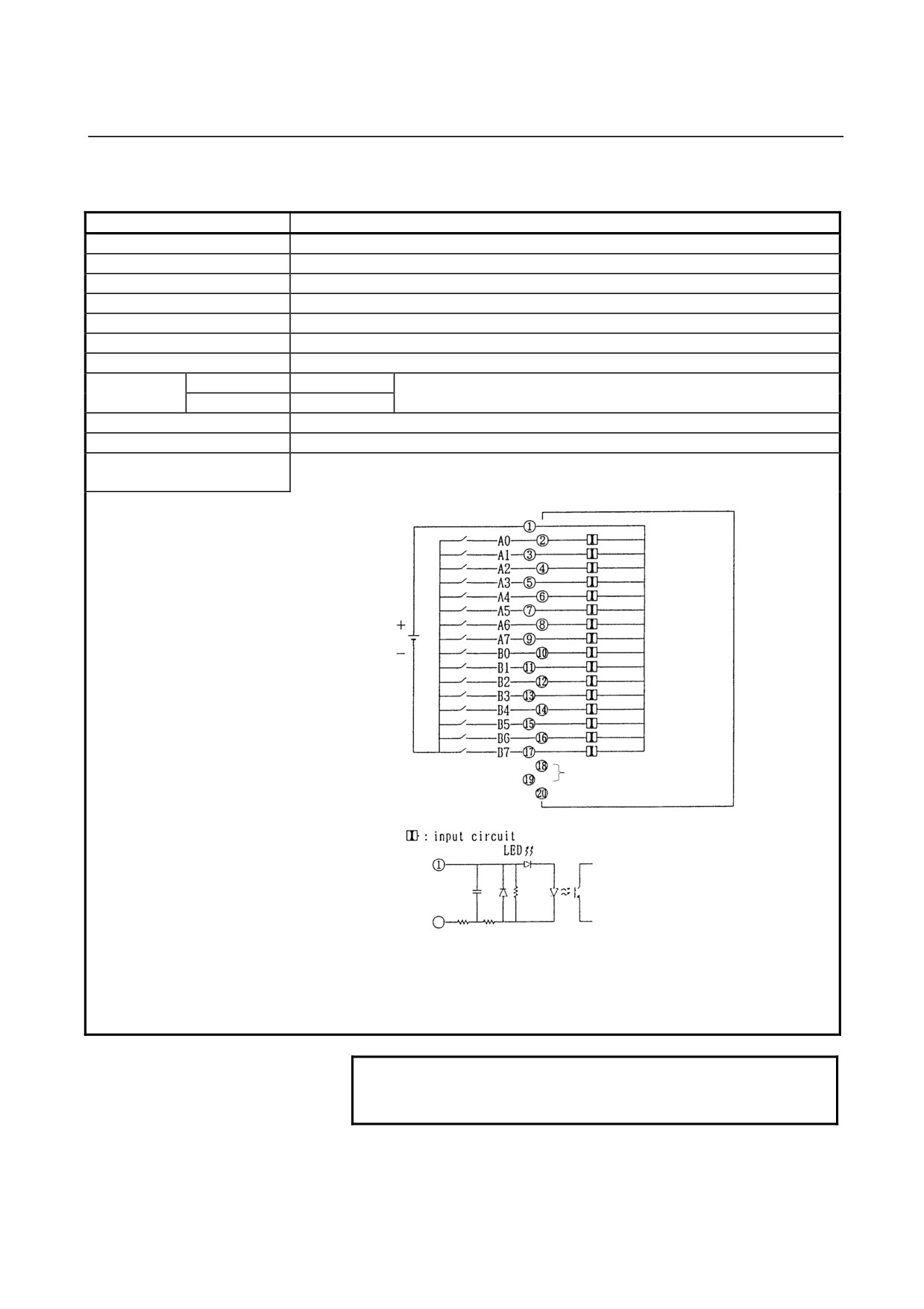
(4) Input module AID16C
Item
Specifications
Points/module
16 points
Points/common
16 points/common
Sink/source current
Source current type
Input voltage
24VDC +10%, −20%
Input current
7.5mA (average)
ON voltage, current
Min. 15VDC, min. 4mA
OFF voltage, current
Max. 5VDC, max. 1.5mA
Response time
OFF→ON
Max.20ms
This is the value from input to output in the module. The actual value is
ON→OFF
Max.20ms
determined by adding it to the scanning time depending on each
system.
Input display
LED display
External connection
Terminal block connector (20 terminals, M3.5 screw terminal)
Terminal connection and
circuitry
(Note)
NOTE
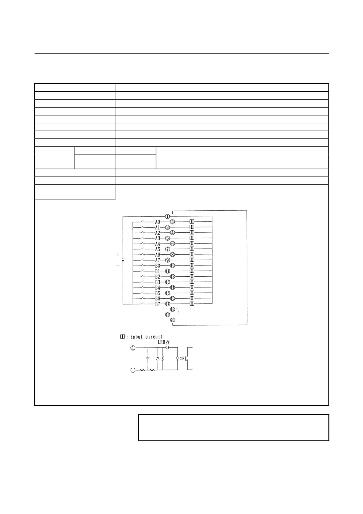
Pins 18 and 19 are for factory use only.
Do not connect any wire to them
- 40 -
B-61813E/04
CONNECTION5.DIGITAL INPUT/OUTPUT MODULES
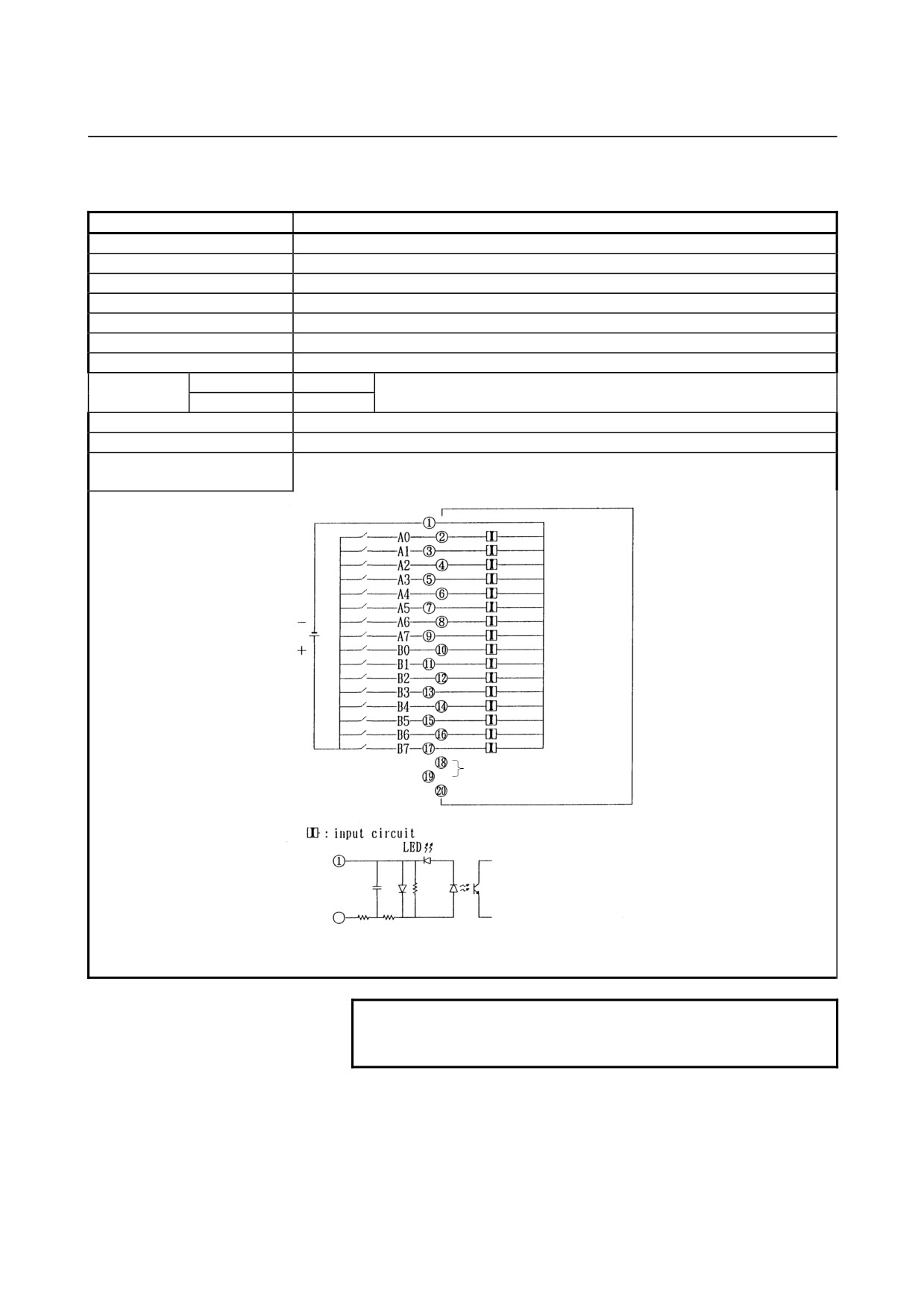
(5) Input module AID16K
Item
Specifications
Points/module
16 points
Points/common
16 points/common
Sink/source current
Source current type
Input voltage
24VDC +10%, −20%
Input current
7.5mA (average)
ON voltage, current
Min. 15VDC, min. 4mA
OFF voltage, current
Max. 5VDC, max. 1.5mA
Response time
OFF→ON
Max.2ms
This is the value from input to output in the module. The actual value is
ON→OFF
Max.2ms
determined by adding it to the scanning time depending on each system.
Input display
LED display
External connection
Terminal block connector (20 terminals, M3.5 screw terminal)
Terminal connection and
circuitry
(Note)
NOTE
Pins 18 and 19 are for factory use only.
Do not connect any wire to them
- 41 -
5.DIGITAL INPUT/OUTPUT MODULESCONNECTION
B-61813E/04
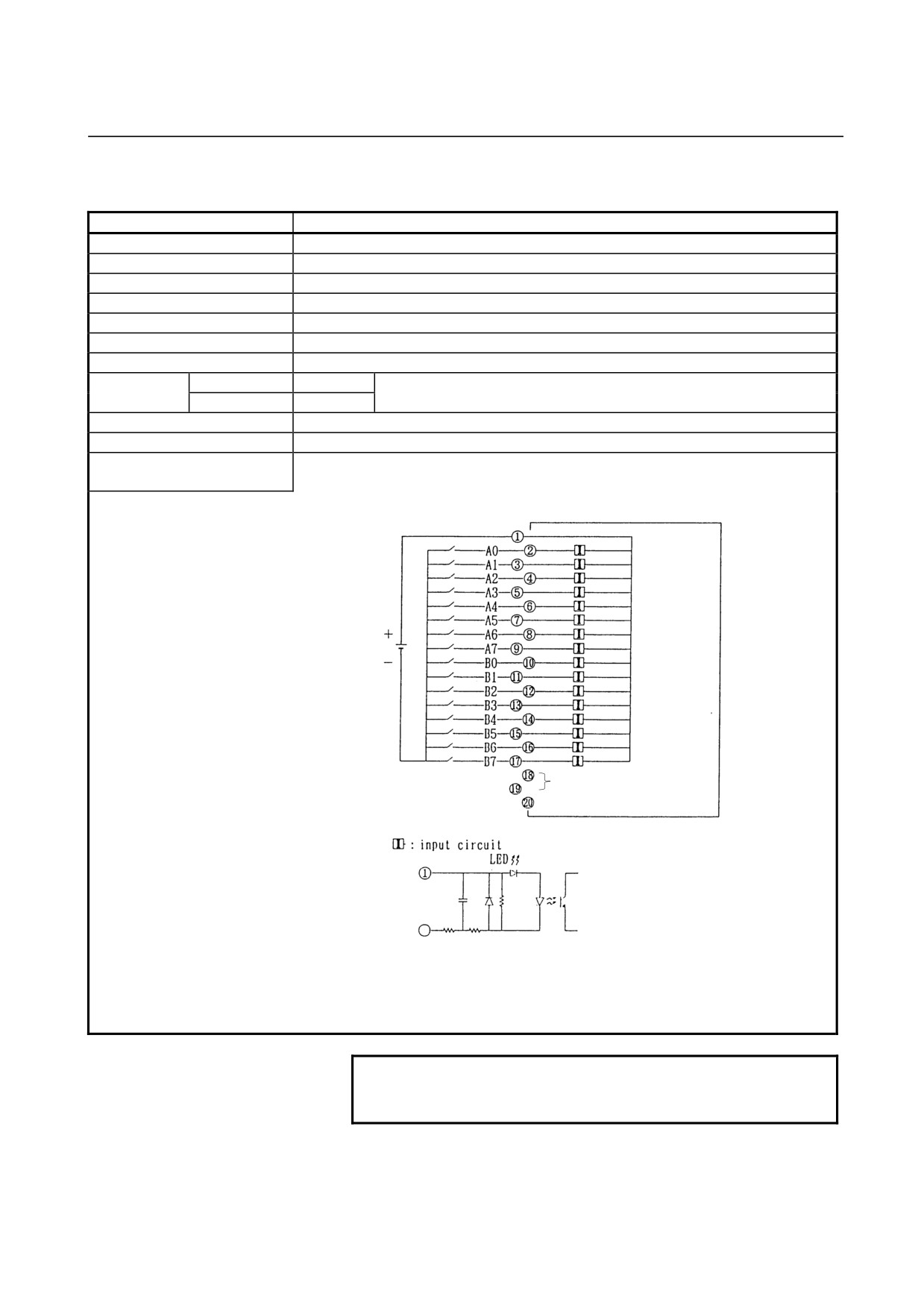
(6) Input module AID16D
Item
Specifications
Points/module
16 points
Points/common
16 points/common
Sink/source current
Sink current type
Input voltage
24VDC +10%, −20%
Input current
7.5mA (average)
ON voltage, current
Min. 15VDC, min. 4mA
OFF voltage, current
Max. 5VDC, max. 1.5mA
Response time
OFF→ON
Max.20ms
This is the value from input to output in the module. The actual value is
ON→OFF
Max.20ms
determined by adding it to the scanning time depending on each system.
Input display
LED display
External connection
Terminal block connector (20 terminals, M3.5 screw terminal)
Terminal connection and
circuitry
(Note)
NOTE
Pins 18 and 19 are for factory use only.
Do not connect any wire to them
- 42 -
B-61813E/04
CONNECTION5.DIGITAL INPUT/OUTPUT MODULES
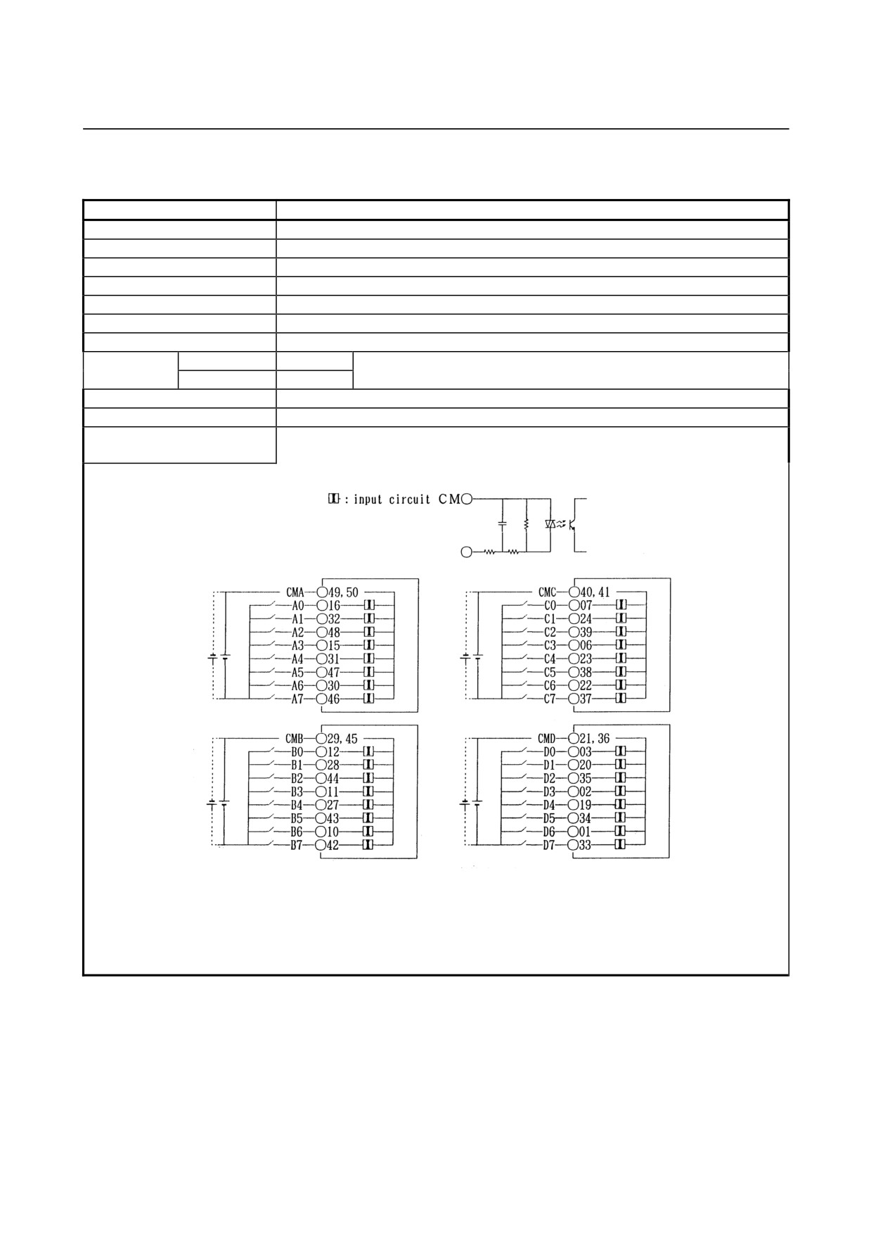
(7) Input module AID16L
Item
Specifications
Points/module
16 points
Points/common
16 points/common
Sink/source current
Sink current type
Input voltage
24VDC +10%, −20%
Input current
7.5mA (average)
ON voltage, current
Min. 15VDC, min. 4mA
OFF voltage, current
Max. 5VDC, max. 1.5mA
Response time
OFF→ON
Max.2ms
This is the value from input to output in the module. The actual value is
ON→OFF
Max.2ms
determined by adding it to the scanning time depending on each system.
Input display
LED display
External connection
Terminal block connector (20 terminals, M3.5 screw terminal)
Terminal connection and
circuitry
(Note)
NOTE
Pins 18 and 19 are for factory use only.
Do not connect any wire to them
- 43 -
5.DIGITAL INPUT/OUTPUT MODULESCONNECTION
B-61813E/04
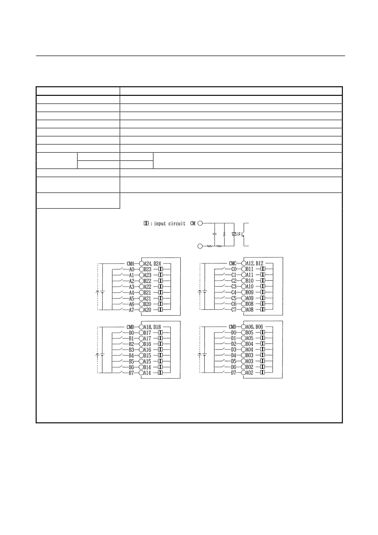
(8) Input module AID32E1
Item
Specifications
Points/module
32 points
Points/common
8 points/common
Sink/source current
Both directions
Input voltage
24VDC +10%, −20%
Input current
7.5mA (average)
ON voltage, current
Min. 15VDC, min. 4.5mA
OFF voltage, current
Max. 6VDC, max. 2mA
Response time
OFF→ON
Max.20ms
This is the value from input to output in the module. The actual value is
ON→OFF
Max.20ms
determined by adding it to the scanning time depending on each system.
Input display
Not provided
External connection
Connector (HONDA TSUSHIN MR-50RMA)
Terminal connection and
circuitry
- 44 -
B-61813E/04
CONNECTION5.DIGITAL INPUT/OUTPUT MODULES
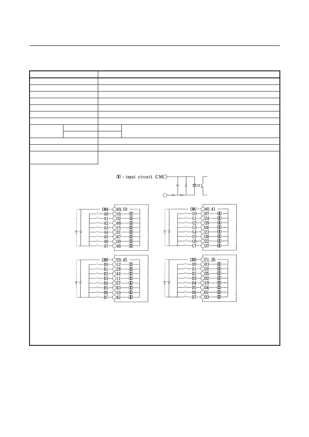
(9) Input module AID32E2
Item
Specifications
Points/module
32 points
Points/common
8 points/common
Sink/source current
Both directions
Input voltage
24VDC +10%, −20%
Input current
7.5mA (average)
ON voltage, current
Min. 15VDC, min. 4.5mA
OFF voltage, current
Max. 6VDC, max. 2mA
Response time
OFF→ON
Max.20ms
This is the value from input to output in the module. The actual value is
ON→OFF
Max.20ms
determined by adding it to the scanning time depending on each system.
Input display
Not provided
External connection
Connector (HIROSE ELECTRIC HIF3BB-50PA-2.54DS in accordance with MIL
standard)
Terminal connection and
circuitry
- 45 -
5.DIGITAL INPUT/OUTPUT MODULESCONNECTION
B-61813E/04
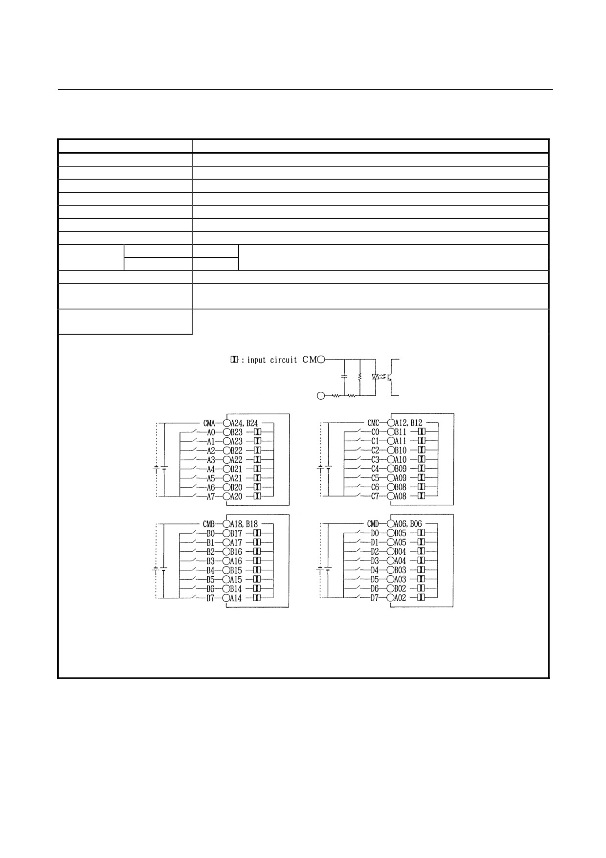
(10) Input module AID32F1
Item
Specifications
Points/module
32 points
Points/common
8 points/common
Sink/source current
Both directions
Input voltage
24VDC +10%, −20%
Input current
7.5mA (average)
ON voltage, current
Min. 15VDC, min. 4.5mA
OFF voltage, current
Max. 6VDC, max. 2mA
Response time
OFF→ON
Max.2ms
This is the value from input to output in the module. The actual value is
ON→OFF
Max.2ms
determined by adding it to the scanning time depending on each system.
Input display
Not provided
External connection
Connector (HONDA TSUSHIN MR-50RMA)
Terminal connection and
circuitry
- 46 -
B-61813E/04
CONNECTION5.DIGITAL INPUT/OUTPUT MODULES
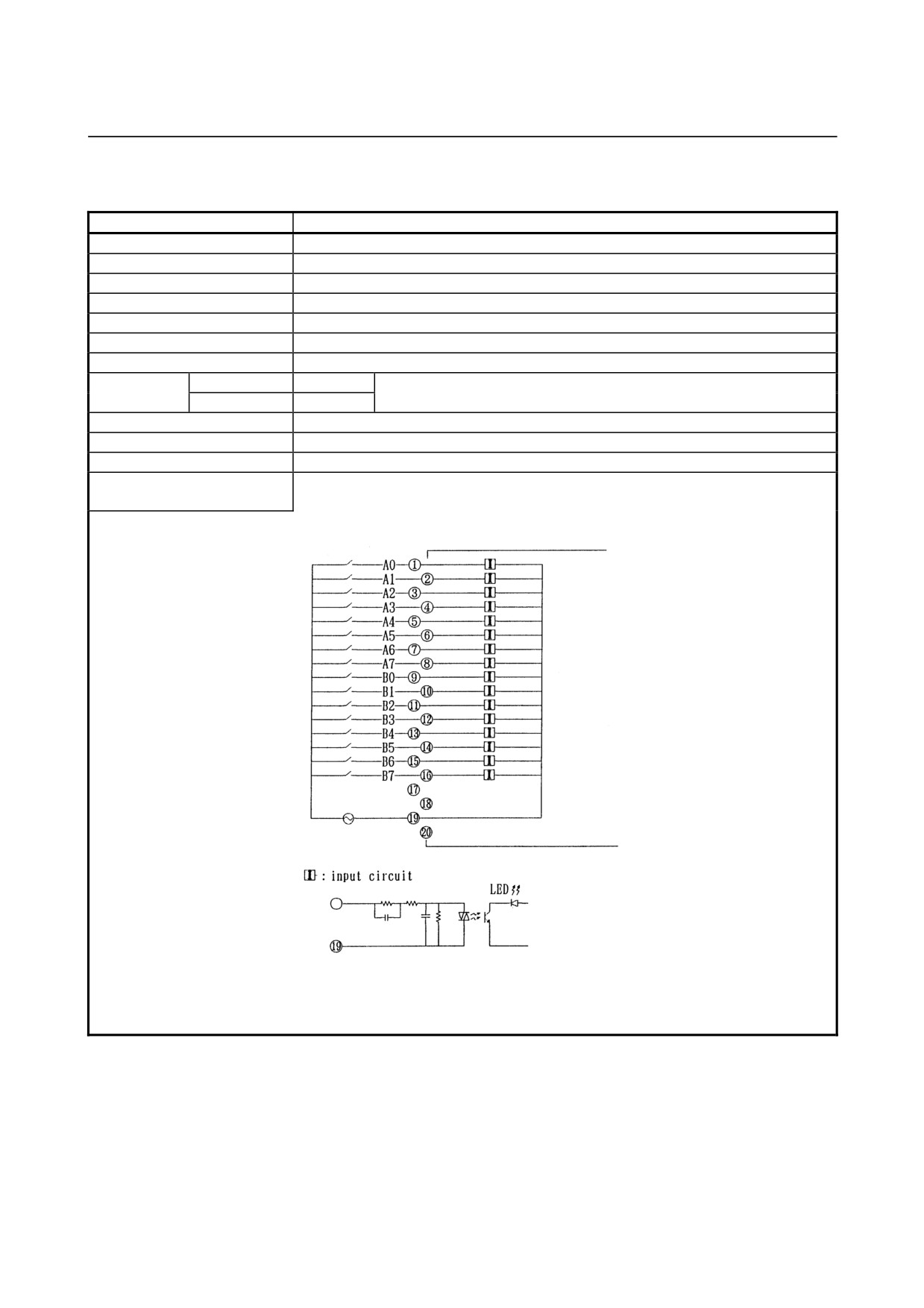
(11) Input module AID32F2
Item
Specifications
Points/module
32 points
Points/common
8 points/common
Sink/source current
Both directions
Input voltage
24VDC +10%, −20%
Input current
7.5mA (average)
ON voltage, current
Min. 15VDC, min. 4.5mA
OFF voltage, current
Max. 6VDC, max. 2mA
Response time
OFF→ON
Max.2ms
This is the value from input to output in the module. The actual value is
ON→OFF
Max.2ms
determined by adding it to the scanning time depending on each system.
Input display
Not provided
External connection
Connector (HIROSE ELECTRIC HIF3BB-50PA-2.54DS in accordance with MIL
standard)
Terminal connection and
circuitry
- 47 -
5.DIGITAL INPUT/OUTPUT MODULESCONNECTION
B-61813E/04
(12) Input module AIA16G
Item
Specifications
Points/module
16 points
Points/common
16 points/common
Sink/source current
100 to 115VAC ±15%
Input voltage
132Vrms, 50/60 Hz
Input current
10.55mArms (120VAC, 50Hz)
ON voltage, current
Min. 74Vrms, min. 6mArms
OFF voltage, current
Max. 20Vrms, max. 2.2mArms
Response time
OFF→ON
Max.35ms
This is the value from input to output in the module. The actual value is
ON→OFF
Max.45ms
determined by adding it to the scanning time depending on each system.
Input display
LED display
External connection
Terminal block connector (20 terminals, M3.5 screw terminal)
Common
16 points/common
Terminal connection and
circuitry
- 48 -
B-61813E/04
CONNECTION5.DIGITAL INPUT/OUTPUT MODULES
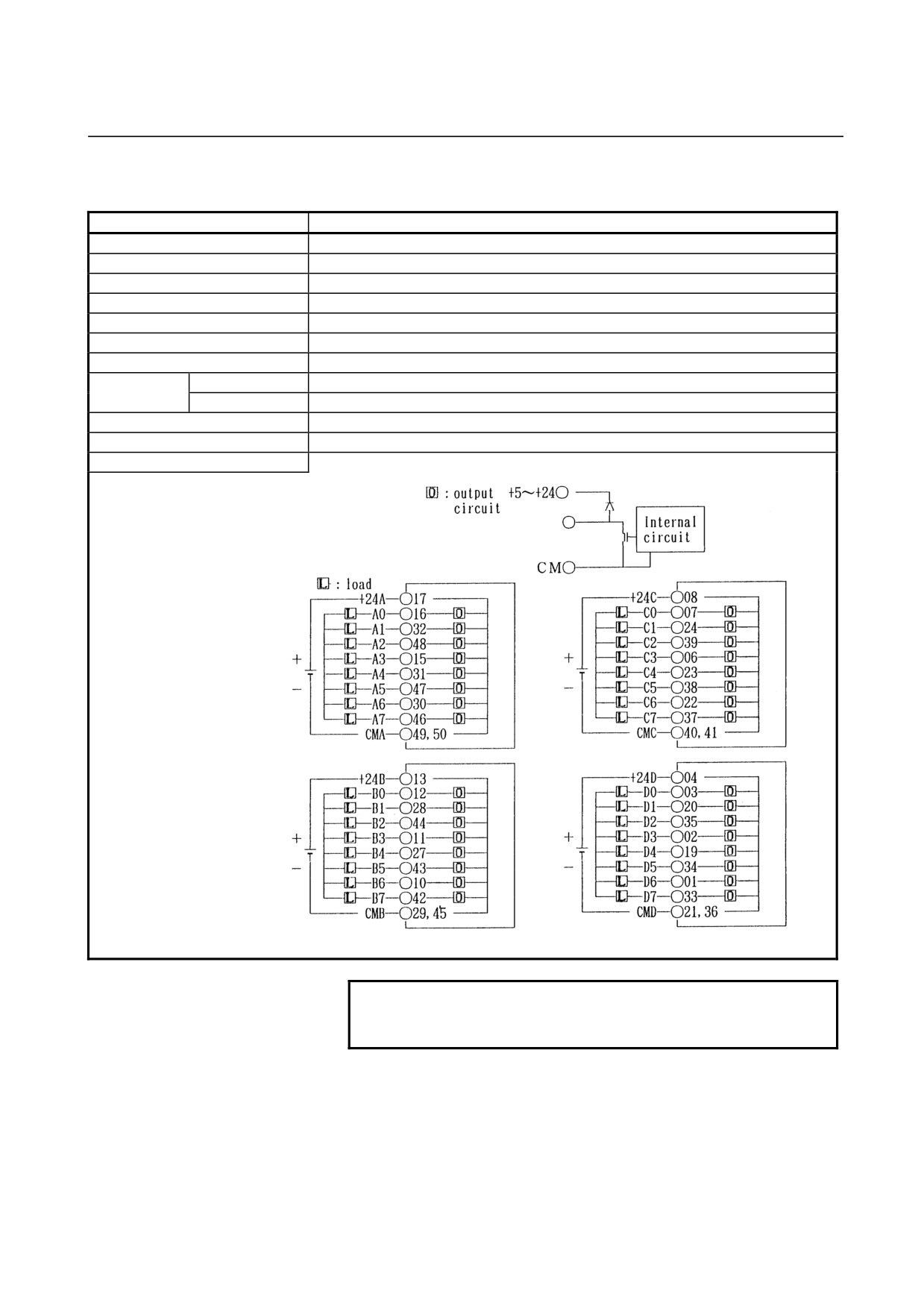
(13) Output module AOD32A1 (Non-insulation type)
Item
Specifications
Points/module
32 points
Points/common
8 points/common
Sink/source current
Sink current type
Rated load voltage
5 to 24VDC +20%, −15%
Maximum load current
0.3A (however 2A/common)
Maximum voltage drop when ON
0.24V (load current ×0.8Ω)
Maximum leak current when OFF
0.1mA
Response time
OFF→ON
Max.1ms
ON→OFF
Max.1ms
Input display
Not provided
External connection
Connector (HONDA TSUSHIN MR-50RMA)
Terminal connection and circuitry
NOTE
For the common (CMA, CMB, CMC, CMD) , make
sure to use both of them.
- 49 -
5.DIGITAL INPUT/OUTPUT MODULESCONNECTION
B-61813E/04
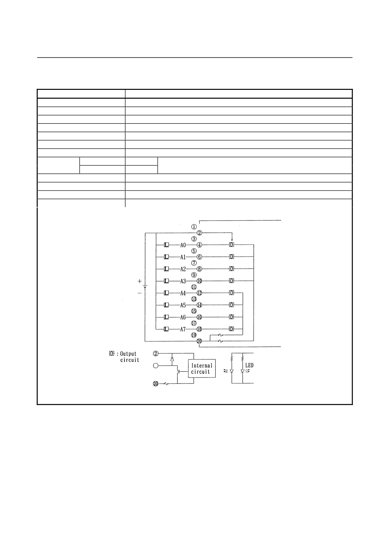
(14) Output module AOD08C
Item
Specifications
Points/module
8 points
Points/common
8 points/common
Sink/source current
Sink current type
Rated load voltage
12 to 24VDC +20%, −15%
Maximum load current
2A (however 4A/fuse)
Maximum voltage drop when ON
0.8V (load current ×0.4Ω)
Maximum leak current when OFF
0.1mA
Response time
OFF→ON
Max.2ms
This is the value from input to output in the module. The actual value is
ON→OFF
Max.2ms
determined by adding it to the scanning time depending on each system.
Input display
LED display
External connection
Terminal block connector (20 terminals, M3.5 screw terminal)
Fuse
5A, 1 piece for each output A0-A3 and A4-A7.
Terminal connection and circuitry
- 50 -
B-61813E/04
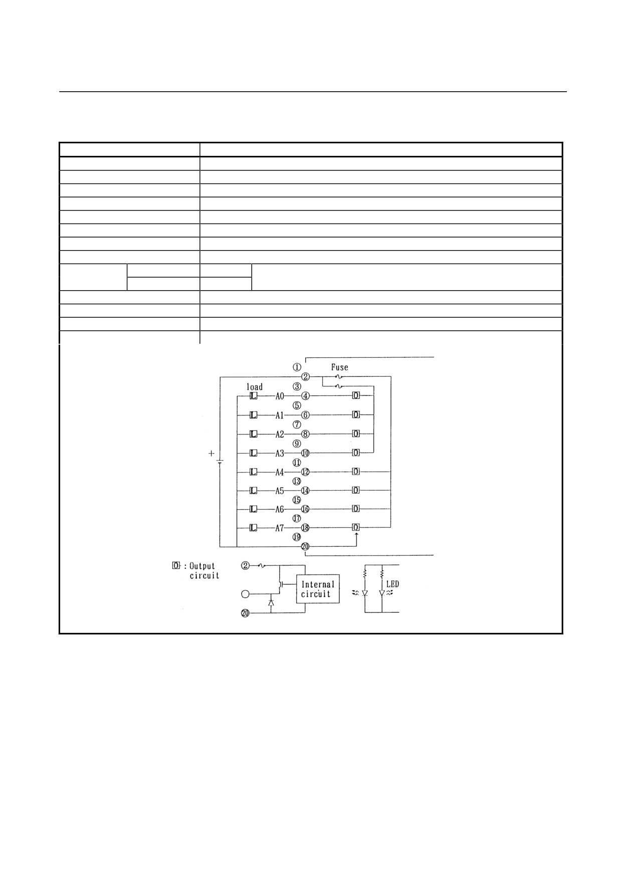
CONNECTION5.DIGITAL INPUT/OUTPUT MODULES
(15) Output module AOD08D
Item
Specifications
Points/module
8 points
Points/common
8 points/common
Sink/source current
Source current type
Rated load voltage
12 to 24VDC +20%, −15%
Maximum load current
2A (however 4A/fuse)
Limit of load
Refer to load derating curve (Fig. 5.3(a))
Maximum voltage drop when ON
1.2V (load current ×0.6Ω)
Maximum leak current when OFF
0.1mA
Response
OFF→ON
Max.2ms
This is the value from input to output in the module. The actual value is
Time
ON→OFF
Max.2ms
determined by adding it to the scanning time depending on each system.
Output display
LED display
External connection
Terminal block connector (20 terminals, M3.5 screw terminal)
Fuse
5A, 1 piece for each output A0-A3 and A4-A7.
Terminal connection and circuitry
- 51 -
5.DIGITAL INPUT/OUTPUT MODULESCONNECTION
B-61813E/04
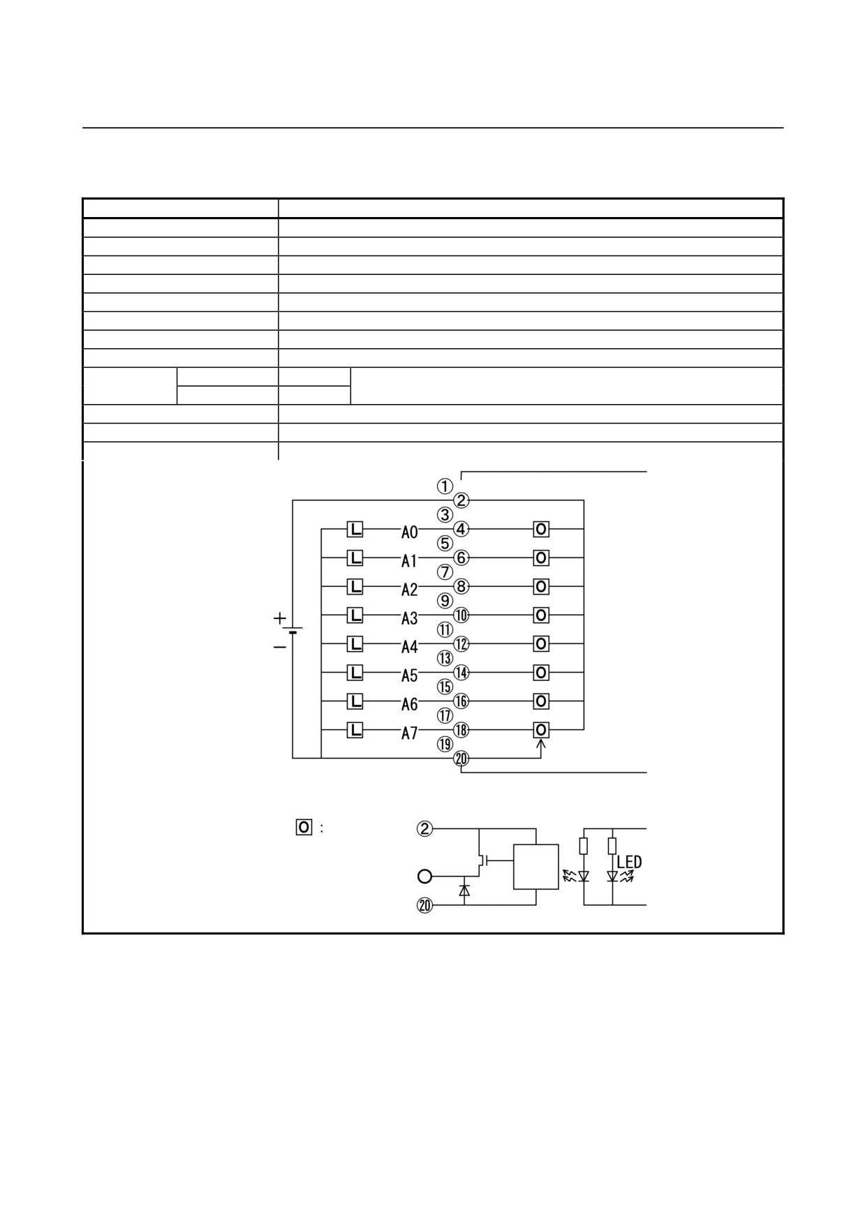
(16) Output module AOD08DP
Item
Specifications
Points/module
8 points
Points/common
8 points/common
Sink/source current
Source current type
Rated load voltage
12 to 24VDC +20%, −15%
Maximum load current
2A (however 8A/common)
Output current limit
2.8A (Min.)
Maximum voltage drop when ON
0.18V (load current ×0.09Ω)
Maximum leak current when OFF
0.1mA
Response
OFF→ON
Max.2ms
This is the value from input to output in the module. The actual value is
Time
ON→OFF
Max.2ms
determined by adding it to the scanning time depending on each system.
Output display
LED display
External connection
Terminal block connector (20 terminals, M3.5 screw terminal)
Terminal connection and circuitry
Load
Output
circuit
Internal
circuit
- 52 -
B-61813E/04
CONNECTION5.DIGITAL INPUT/OUTPUT MODULES
•
AOD08DP output protection
The internal circuit of this output module can detect a load
overcurrent and driver temperature. To be specific, if the load
current increases abnormally, for example, because of a
wiring ground fault, the internal limiter of the driver
suppresses the output current. If this condition lasts long, the
driver can get abnormally hot, thus causing the protection
circuit to turn off the output. After the output is turned off
and the driver temperature becomes lower, the protection
function is automatically reset to turn on the output; this
OFF/ON operations are repeated.
When the overheat protection circuit works to turn off the
output, the LED "F" on the front of the module lights red.
If the protection circuit turns off the output, the output
module can detect which DO has encountered the
abnormality, using a DI. This function can be allocated to
any DI address (1 byte). If an abnormality is detected, the DI
bit corresponding to the DO of interest switches between "1"
and "0". The DI bit stays "1" for at least 10 ms.
If the protection function worked, turn off the power for both
the DO and system, and remove the cause of the overload.
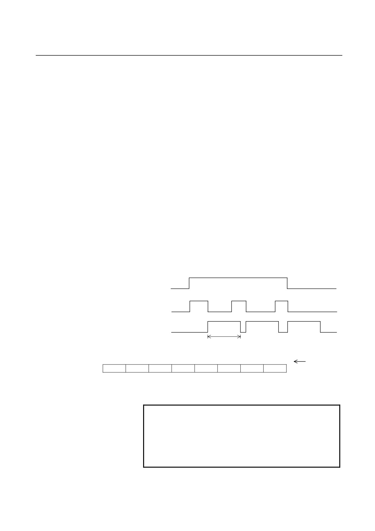
The following timing chart shows how the output and DI
behave when the output protection function works.
DO
Output
DI
10msec or more
7
6
5
4
3
2
1
0
Bit number
DI(Xm)
A7
A6
A5
A4
A3
A2
A1
A0
The DI bit having the same bit number as the DO (A0 to A7)
bit where an abnormality was detected becomes "1".
NOTE
An overcurrent prolonged, for example, because of
a wiring ground fault may lead to the break-down of
a module. To avoid this failure, build a sequence
program that can turn off the DO corresponding to
the bit number of the DI bit which has been set to "1"
because of a failure detected on the driver.
- 53 -
5.DIGITAL INPUT/OUTPUT MODULESCONNECTION
B-61813E/04
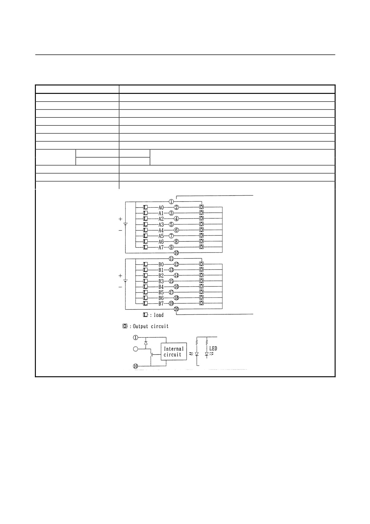
(17) Output module AOD16C
Item
Specifications
Points/module
16 points
Points/common
8 points/common
Sink/source current
Sink current type
Rated load voltage
12 to 24VDC +20%, −15%
Maximum load current
0.5A (however 2A/common)
Maximum voltage drop when ON
0.7V (load current ×1.4Ω)
Maximum leak current when OFF
0.1mA
Response time
OFF→ON
Max.2ms
This is the value from input to output in the module. The actual value is
ON→OFF
Max.2ms
determined by adding it to the scanning time depending on each system.
Output display
LED display
External connection
Terminal block connector (20 terminals, M3.5 screw terminal)
Terminal connection and circuitry
- 54 -
B-61813E/04
CONNECTION5.DIGITAL INPUT/OUTPUT MODULES
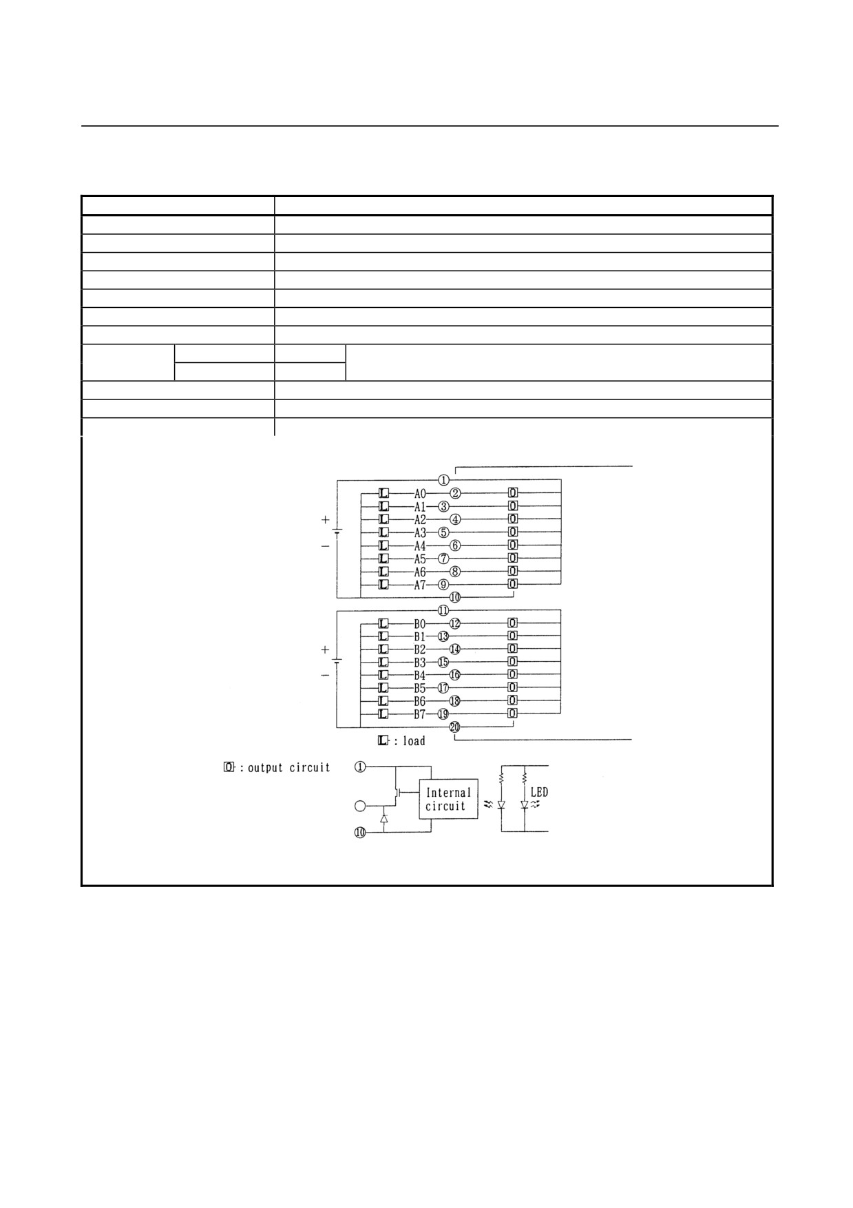
(18) Output module AOD16D
Item
Specifications
Points/module
16 points
Points/common
8 points/common
Sink/source current
Source current type
Rated load voltage
12 to 24VDC +20%, −15%
Maximum load current
0.5A (however 2A/common)
Maximum voltage drop when ON
0.7V (load current ×1.4Ω)
Maximum leak current when OFF
0.1mA
Response time
OFF→ON
Max.2ms
This is the value from input to output in the module. The actual value is
ON→OFF
Max.2ms
determined by adding it to the scanning time depending on each system.
Output display
LED display
External connection
Terminal block connector (20 terminals, M3.5 screw terminal)
Terminal connection and circuitry
- 55 -
5.DIGITAL INPUT/OUTPUT MODULESCONNECTION
B-61813E/04
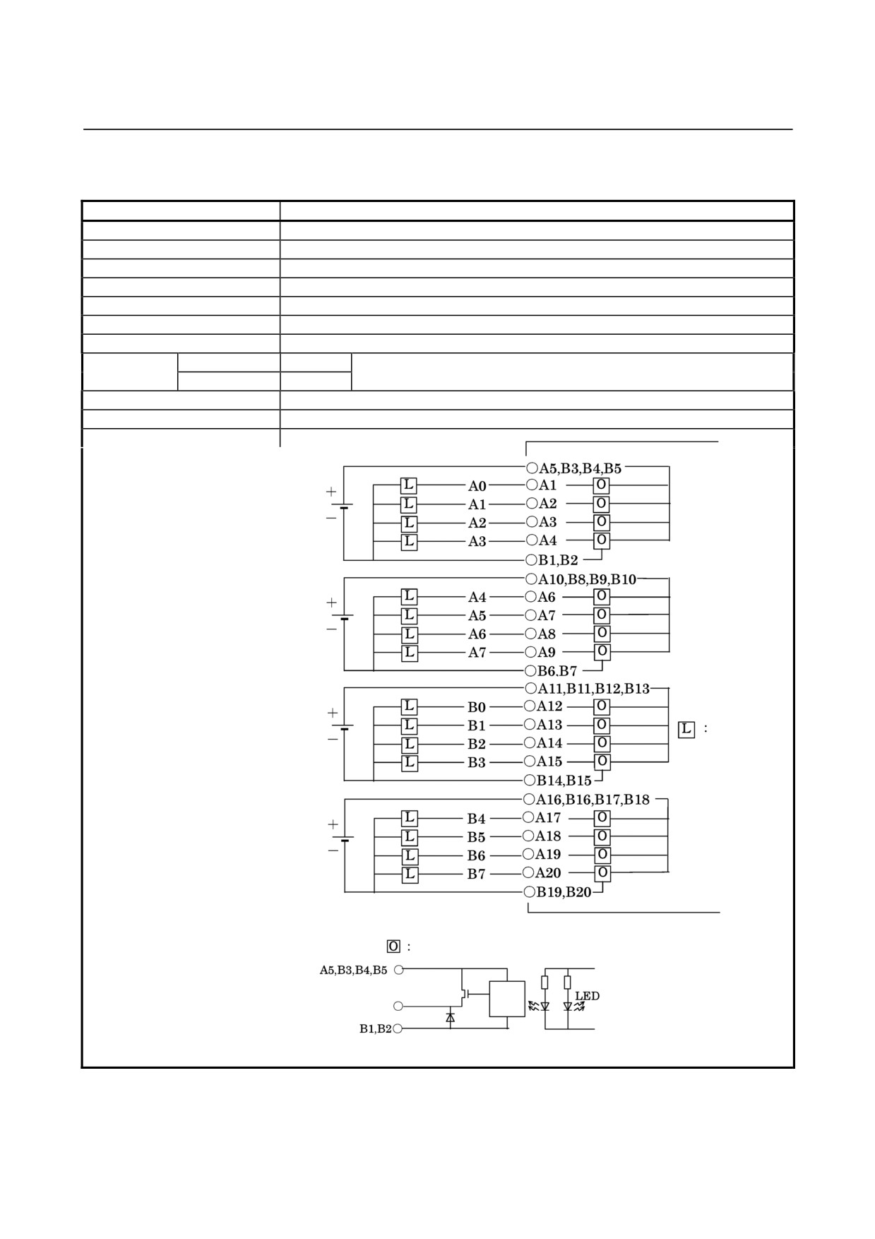
(19) Output module AOD16D2
Item
Specifications
Points/module
16 points
Points/common
4 points/common
Sink/source current
Source current type
Rated load voltage
12 to 24VDC +20%, −15%
Maximum load current
2A (4A/common)
Maximum voltage drop when ON
0.4V (load current ×0.2Ω)
Maximum leak current when OFF
0.1mA
Response time
OFF→ON
Max.2ms
This is the value from input to output in the module. The actual value is
ON→OFF
Max.2ms
determined by adding it to the scanning time depending on each system.
Output display
LED display
External connection
Connector (HIROSE ELECTRIC HIF4-40P-3.18DS)
Terminal connection and circuitry
Load
Output circuit
Output terminal
Internal
circuit
- 56 -
B-61813E/04
CONNECTION5.DIGITAL INPUT/OUTPUT MODULES
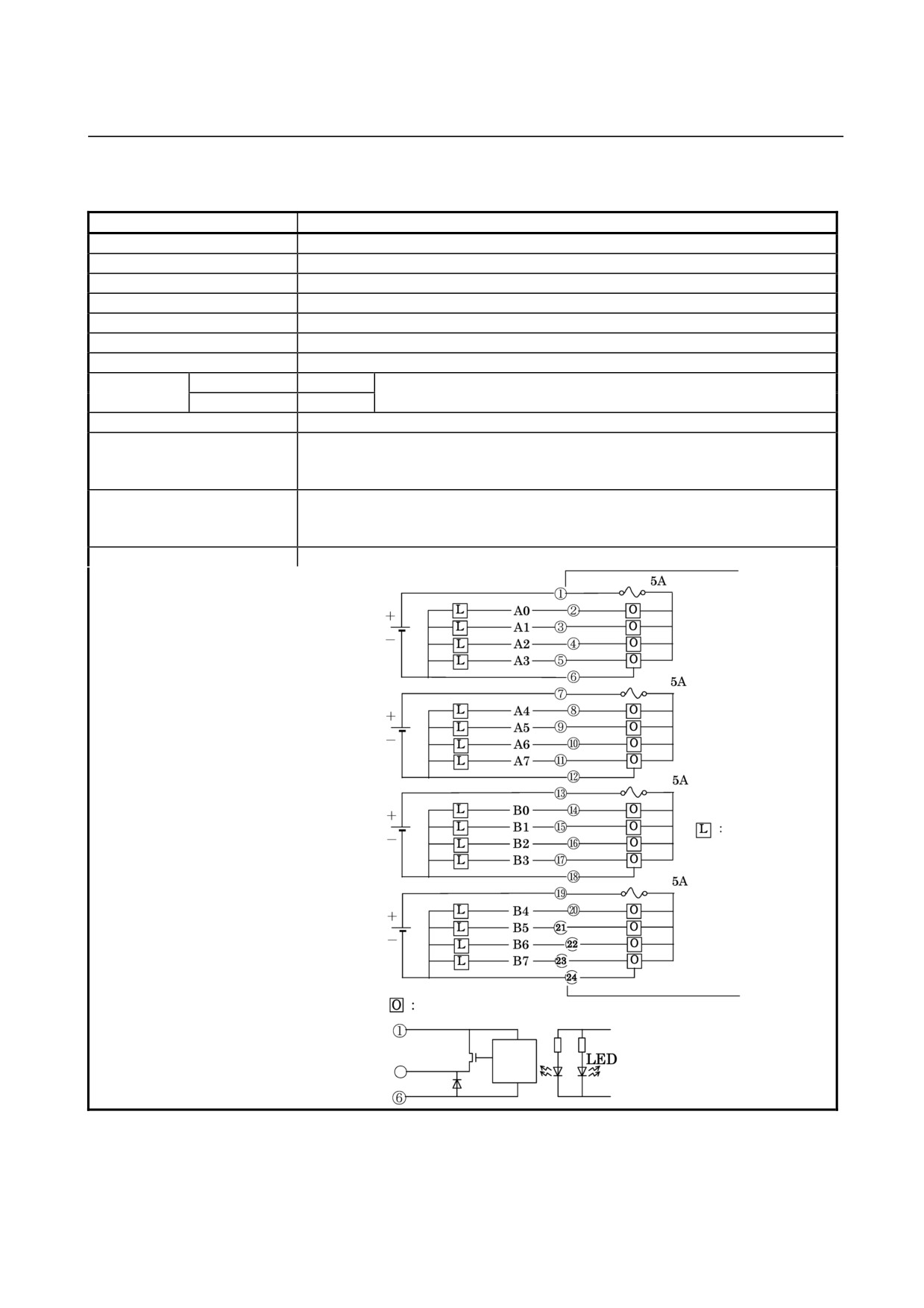
(20) Output module AOD16D3
Item
Specifications
Points/module
16 points
Points/common
4 points/common
Sink/source current
Source current type
Rated load voltage
12 to 24VDC +20%, −15%
Maximum load current
2A (4A/common)
Maximum voltage drop when ON
0.4V (load current ×0.2Ω)
Maximum leak current when OFF
0.1mA
Response time
OFF→ON
Max.2ms
This is the value from input to output in the module. The actual value is
ON→OFF
Max.2ms
determined by adding it to the scanning time depending on each system.
Output display
LED display
External connection
24-pin terminal block (BL3.5/24/90F) manufactured by Weidmüler
Conformable wire (maximum): 1.5 mm2 (VDE)/AWG 14 (UL/CSA)
Note: The terminal block for the cable comes with this module.
Fuse
One 5A fuse for each of output sets A0 to A3, A4 to A7, B0 to B3, and B4 to B7
MP50 (A60L-0001-0046#5.0) manufactured by Daito.
Ordering information for a 4-fuse set: A03B-0819-K104
Terminal connection and circuitry
Fuse
Fuse
Fuse
Load
Fuse
Output circuit
Output terminal
Internal
circuit
- 57 -