FANUC Alpha Series Motors and Modular Drives. Maintenance Manual (GFZ-65165E/02) - page 5

2. ALARM NUMBERS AND
BRIEF DESCRIPTIONS
TROUBLESHOOTING
B-65165E/02
2
ALARM NUMBERS AND BRIEF
DESCRIPTIONS
- 98 -
2. ALARM NUMBERS AND
B-65165E/02
TROUBLESHOOTING
BRIEF DESCRIPTIONS
2.1
FOR SERIES 16i, 18i, 20i, 21i, AND Power Mate i
Servo alarm
Alarm
SVM
SPM
PSM
Description
Remarks
No.
360
Pulse coder checksum error (built-in)
3.3.7 (1)
361
Pulse coder phase error (built-in)
3.3.7 (1)
363
Clock error (built-in)
3.3.7 (1)
364
Soft phase alarm (built-in)
3.3.7 (1)
365
LED error (built-in)
3.3.7 (1)
366
Pulse error (built-in)
3.3.7 (1)
367
Count error (built-in)
3.3.7 (1)
368
Serial data error (built-in)
3.3.7 (3)
369
Data transfer error (built-in)
3.3.7 (3)
380
LED error (separate)
3.3.7 (2)
381
Pulse coder phase error (separate)
3.3.7 (2)
382
Count error (separate)
3.3.7 (2)
383
Pulse error (separate)
3.3.7 (2)
384
Soft phase alarm (separate)
3.3.7 (2)
385
Serial data error (separate)
3.3.7 (3)
386
Data transfer error (separate)
3.3.7 (3)
417
Invalid parameter
3.3.6
421
Excessive semi-full error
3.3.8
430
Servomotor overheat
3.3.5
431
03
Converter: main circuit overload
3.1
432
06
Converter: control undervoltage/open
3.1
phase
433
04
Converter: DC link undervoltage
3.1
434
2
Inverter: control power supply
3.2
undervoltage
435
5
Inverter: DC link undervoltage
3.2
436
Soft thermal (OVC)
3.3.3
437
01
Converter: input circuit overcurrent
3.1
438
8
Inverter: current alarm
(L axis)
3.2
9
(M axis)
A
(N axis)
b
(L and M axes)
C
(M and N axes)
d
(L and N axes)
E
(L, M, and N axes)
439
07
Converter: DC link overvoltage
3.1
440
08
Converter excessive deceleration power
3.1
- 99 -
2. ALARM NUMBERS AND
BRIEF DESCRIPTIONS
TROUBLESHOOTING
B-65165E/02
Alarm
SVM
SPM
PSM
Description
Remarks
No.
441
Current offset error
3.3.8
442
05
Converter: DC link charging/inverter DB
3.1
443
02
Converter: cooling fan stopped
3.1
444
1
Inverter: internal cooling fan stopped
3.2
445
Soft disconnection alarm
3.3.4
446
Hard disconnection alarm
Not
issued
447
Hard disconnection alarm (separate)
3.3.4
448
Feedback mismatch alarm
3.3.8
449
8.
Inverter: IPM alarm
(L axis)
3.2
9.
(M axis)
A.
(N axis)
b.
(L and M axes)
C.
(M and N axes)
d.
(L and N axes)
E.
(L, M, and N axes)
453
Soft disconnection alarm (α pulse coder)
3.3.4
Spindle alarm (n represents a spindle number. Example: n = 1 for the
first spindle)
Alarm
SVM
SPM
PSM
Description
Remarks
No.
749
A
Program ROM error
3.4
749
A0
Program ROM error
3.4
749
A1
Program RAM error
3.4
749
A2
Program RAM error
3.4
749
A3
SPM control circuit clock error
3.4
749
A4
SRAM parity error
3.4
7n01
01
Motor overheat
3.4
7n02
02
Excessive speed deviation
3.4
7n03
03
DC link fuse blown
3.4
7n04
04
06
Input power supply open phase and power
3.4
supply failure
7n07
07
Excessive speed
3.4
7n09
09
Main circuit overload
3.4
7n11
11
07
DC link overvoltage
3.4
7n12
12
DC link overcurrent/IPM alarm
3.4
750
13
CPU internal data memory error
3.4
7n15
15
Output switching/spindle switching alarm
3.4
750
16
RAM error
3.4
750
19
Excessive offset of the phase U current
3.4
detection circuit
750
20
Excessive offset of the phase V current
3.4
detection circuit
- 100 -
2. ALARM NUMBERS AND
B-65165E/02
TROUBLESHOOTING
BRIEF DESCRIPTIONS
(n represents a spindle number. Example: n = 1 for the first spindle)
Alarm
SVM
SPM
PSM
Description
Remarks
No.
749
24
Serial transfer data error
3.4
749
25
Setting data transfer stopped
3.4
7n26
26
Cs contour control speed detection signal
3.4
disconnected
7n27
27
Position coder signal disconnected
3.4
7n28
28
Cs contour control position detection
3.4
signal disconnected
7n29
29
Short-period overload
3.4
7n30
30
01
PSM main circuit overcurrent
3.4
7n31
31
Speed detection signal disconnected and
3.4
motor lock alarm
750
32
Serial communication LSI internal RAM
3.4
error
7n33
33
05
DC link precharge failure
3.4
7n34
34
Parameter data out of the specifiable
3.4
range
7n35
35
Too large of a gear ratio is specified.
3.4
7n36
36
Error counter overflow
3.4
7n37
37
Speed detector parameter error
3.4
7n39
39
Cs contour control one-rotation signal
3.4
detection error
7n40
40
Cs contour control one-rotation signal not
3.4
detected
7n41
41
Position coder one-rotation signal
3.4
detection error
7n42
42
Position coder one-rotation signal not
3.4
detected
7n43
43
Differential speed mode position coder
3.4
signal disconnected
7n44
44
A/D conversion error
3.4
7n46
46
Position coder one-rotation signal
3.4
detection error during thread cutting
7n47
47
Position coder signal error
3.4
7n48
49
Excessive differential speed conversion
3.4
result
7n50
50
Excessive speed command calculation
3.4
value during spindle synchronization
7n51
51
04
DC link undervoltage
3.4
7n52
52
ITP signal error I
3.4
7n53
53
ITP signal error II
3.4
7n54
54
Current overload alarm
3.4
7n55
55
Power line state error at spindle
3.4
switching/output switching
7n56
56
Control circuit cooling fan stopped
3.4
7n56
57
08
Excessive regenerated power
3.4
7n58
58
03
PSM main circuit overload
3.4
7n59
59
02
PSM cooling fan stopped
3.4
- 101 -
2. ALARM NUMBERS AND
BRIEF DESCRIPTIONS
TROUBLESHOOTING
B-65165E/02
2.2
FOR SERIES 15i
Servo alarm
Alarm
SVM
SPM
PSM
Description
Remarks
No.
SV0027
Invalid digital servo parameter setting
3.3.6
SV0360
Pulse coder checksum error (built-in)
3.3.7 (1)
SV0361
Pulse coder phase error (built-in)
3.3.7 (1)
SV0363
Clock error (built-in)
3.3.7 (1)
SV0364
Soft phase alarm (built-in)
3.3.7 (1)
SV0365
LED error (built-in)
3.3.7 (1)
SV0366
Pulse error (built-in)
3.3.7 (1)
SV0367
Count error (built-in)
3.3.7 (1)
SV0368
Serial data error (built-in)
3.3.7 (3)
SV0369
Data transfer error (built-in)
3.3.7 (3)
SV0380
LED error (separate)
3.3.7 (2)
SV0381
Pulse coder phase error (separate)
3.3.7 (2)
SV0382
Count error (separate)
3.3.7 (2)
SV0383
Pulse error (separate)
3.3.7 (2)
SV0384
Soft phase alarm (separate)
3.3.7 (2)
SV0385
Serial data error (separate)
3.3.7 (3)
SV0386
Data transfer error (separate)
3.3.7 (3)
SV0421
Excessive semi-full error
3.3.8
SV0430
Servomotor overheat
3.3.5
SV0431
03
Converter: main circuit overload
3.1
SV0432
06
Converter: control undervoltage/open
3.1
phase
SV0433
04
Converter: DC link undervoltage
3.1
SV0434
2
Inverter: control power supply undervoltage
3.2
SV0435
5
Inverter: DC link undervoltage
3.2
SV0436
Soft thermal (OVC)
3.3.3
SV0437
01
Converter: input circuit overcurrent
3.1
SV0438
8
Inverter: current alarm
(L axis)
3.2
9
(M axis)
A
(N axis)
b
(L and M axes)
C
(M and N axes)
d
(L and N axes)
E
(L, M, and N axes)
SV0439
07
Converter: DC link overvoltage
3.1
SV0440
08
Converter excessive deceleration power
3.1
SV0441
Current offset error
3.3.8
- 102 -
2. ALARM NUMBERS AND
B-65165E/02
TROUBLESHOOTING
BRIEF DESCRIPTIONS
Alarm
SVM
SPM
PSM
Description
Remarks
No.
SV0442
05
Converter: DC link charging/inverter DB
3.1
SV0443
02
Converter: cooling fan stopped
3.1
SV0444
1
Inverter: internal cooling fan stopped
3.2
SV0445
Soft disconnection alarm
3.3.4
SV0446
Hard disconnection alarm
Not
issued
SV0447
Hard disconnection alarm (separate)
3.3.4
SV0448
Feedback mismatch alarm
3.3.8
SV0449
8.
Inverter: IPM alarm
(L axis)
3.2
9.
(M axis)
A.
(N axis)
b.
(L and M axes)
C.
(M and N axes)
d.
(L and N axes)
E.
(L, M, and N axes)
Spindle alarm
Alarm
SVM
SPM
PSM
Description
Remarks
No.
SP097x
A
Program ROM error
3.4
SP097x
A0
Program ROM error
3.4
SP097x
A1
Program RAM error
3.4
SP097x
A2
Program RAM error
3.4
SP097x
A3
SPM control circuit clock error
3.4
SP097x
A4
SRAM parity error
3.4
SP0001
01
Motor overheat
3.4
SP0002
02
Excessive speed deviation
3.4
SP0003
03
DC link fuse blown
3.4
SP0004
04
06
Power supply failure
3.4
SP0007
07
Excessive speed
3.4
SP0009
09
Main circuit overload
3.4
SP0011
11
07
DC link overvoltage
3.4
SP0012
12
DC link overcurrent/IPM alarm
3.4
SP098x
13
CPU internal data memory error
3.4
SP0015
15
Output switching/spindle switching alarm
3.4
SP098x
16
RAM error
3.4
19
Excessive offset of the phase U current
3.4
SP098x
detection circuit
20
Excessive offset of the phase V current
3.4
SP098x
detection circuit
SP022x
24
Serial transfer data error
3.4
SP022x
25
Serial data transfer stopped
3.4
- 103 -
2. ALARM NUMBERS AND
BRIEF DESCRIPTIONS
TROUBLESHOOTING
B-65165E/02
Alarm
SVM
SPM
PSM
Description
Remarks
No.
SP0026
26
Cs contour control speed detection signal
3.4
error
SP0027
27
Position coder signal error
3.4
SP0028
28
Cs contour control position detection
3.4
signal error
SP0029
29
Short-period overload
3.4
SP0030
30
01
PSM main circuit overcurrent
‘
SP0031
31
Speed detection signal disconnected and
3.4
motor lock alarm
SP098x
32
Serial communication LSI internal RAM
3.4
error
SP0033
33
05
DC link precharge failure
3.4
SP0034
34
Parameter data out of the specifiable
3.4
range
SP0035
35
Too large of a gear ratio is specified.
3.4
SP0036
36
Error counter overflow
3.4
SP0037
37
Speed detector parameter error
3.4
SP0039
39
Cs contour control one-rotation signal
3.4
detection error
SP0040
40
Cs contour control one-rotation signal not
3.4
detected
SP0041
41
Position coder one-rotation signal
3.4
detection error
SP0042
42
Position coder one-rotation signal not
3.4
detected
SP0043
43
Differential speed mode position coder
3.4
signal error
SP0044
44
A/D conversion error
3.4
SP0046
46
Position coder one-rotation signal
3.4
detection error during thread cutting
SP0047
47
Position coder signal error
3.4
SP0049
49
Excessive differential speed conversion
3.4
result
SP0050
50
Excessive speed command calculation
3.4
value during spindle synchronization
SP0051
51
04
DC link undervoltage
3.4
SP0052
52
ITP signal error I
3.4
SP0053
53
ITP signal error II
3.4
SP0054
54
Current overload alarm
3.4
SP0055
55
Power line state error at spindle
3.4
switching/output switching
SP0056
56
Control circuit cooling fan stopped
3.4
SP0056
57
08
Excessive regenerated power
3.4
SP0058
58
03
PSM main circuit overload
3.4
SP0059
59
02
PSM cooling fan stopped
3.4
- 104 -
2. ALARM NUMBERS AND
B-65165E/02
TROUBLESHOOTING
BRIEF DESCRIPTIONS
2.3
FOR SERIES 16, 18, 20, 21
Servo alarm
Alarm
Diagnosis
SVM
SPM
PSM
Description
Remarks
No.
screen
350
Alarm 3
α pulse coder error alarm
3.3.7
351
Alarm 4
Pulse coder communication error alarm
3.3.7
400
OVL
1
Fan stopped alarm (SVM)
3.2
2
Fan stopped alarm (PSM)
3.1
3
Overheat alarm (PSM)
Overheat alarm (motor)
3.3.5
414
HVA
7
DC link overvoltage alarm
3.1
HCA
8
Abnormal current alarm
(L axis)
3.2
9
(M axis)
A
(N axis)
b
(L, M axis)
C
(M, N axis)
d
(L, N axis)
E
(L, M, N axis)
1
(PSM overcurrent + IPM alarm)
3.1
8.
IPM alarm
(L axis)
3.2
9.
(M axis)
A.
(N axis)
b.
(L, M axis)
C.
(M, N axis)
d.
(L, N axis)
E.
(L, M, N axis)
OVC
Soft thermal (OVC)
3.3.3
LVA
2
Control power supply undervoltage
3.2
alarm
5
DC link undervoltage alarm (SVM)
4
DC link undervoltage alarm (PSM)
3.1
6
Power supply state alarm
FAN
1
Fan stopped alarm (Series 20 only)
3.2
2
Fan stopped alarm (Series 20 only)
3.1
MCC
5
MCC fused, precharge alarm
3.1
OFS
Current conversion error alarm
3.3.8
416
FBA
Feedback disconnected alarm
3.3.4
417
PRM
Invalid servo parameter setting alarm
3.3.6
For
the
correspondence between the diagnosis screen
numbers and names, see the table below.
- 105 -
2. ALARM NUMBERS AND
BRIEF DESCRIPTIONS
TROUBLESHOOTING
B-65165E/02
DGN No.
#7
#6
#5
#4
#3
#2
#1
#0
Alarm 1
200
OVL
LVA
OVC
HCA
HVA
DCA
FBA
OFA
Alarm 2
201
ALD
EXP
Alarm 3
202
CSA
BLA
PHA
RCA
BZA
CKA
SPH
Alarm 4
203
DTE
CRC
STB
PRM
Alarm 5
204
OFS
MCC
LDM
PMS
FAN
DAL
ABF
Spindle alarm
Alarm No.
SVM
SPM
PSM
Description
Remarks
749
A
Program ROM error
3.4
749
A0
Program ROM error
3.4
749
A1
Program RAM error
3.4
749
A2
Program RAM error
3.4
749
A3
SPM control circuit clock error
3.4
749
A4
SRAM parity error
3.4
751 (AL-01)
01
Motor overheat
3.4
751 (AL-02)
02
Excessive velocity error
3.4
751 (AL-03)
03
DC link fuse blown
3.4
751 (AL-04)
04
06
Input power supply open phase and
3.4
power supply failure
751 (AL-07)
07
Overspeed
3.4
751 (AL-09)
09
Main circuit overload
3.4
751 (AL-11)
11
07
DC link overvoltage
3.4
751 (AL-12)
12
DC link overcurrent/IPM alarm
3.4
750
13
CPU internal data memory failure
3.4
751 (AL-15)
15
Speed range switching and spindle
3.4
switching alarm
750
16
RAM error
3.4
750
19
Phase U current detector circuit
3.4
excessive offset
750
20
Phase V current detector circuit
3.4
excessive offset
749
24
Serial transfer data error
3.4
749
25
Serial data transfer stopped
3.4
751 (AL-26)
26
Cs contouring control velocity detection
3.4
signal disconnected
751 (AL-27)
27
Position coder signal disconnected
3.4
751 (AL-28)
28
Cs contouring control position detection
3.4
signal disconnected
751 (AL-29)
29
Short-period overload
3.4
751 (AL-30)
30
01
PSM main circuit overcurrent
3.4
751 (AL-31)
31
Speed detection signal disconnected
3.4
and motor lock alarm
750
32
Serial communication LSI internal RAM
3.4
error
- 106 -
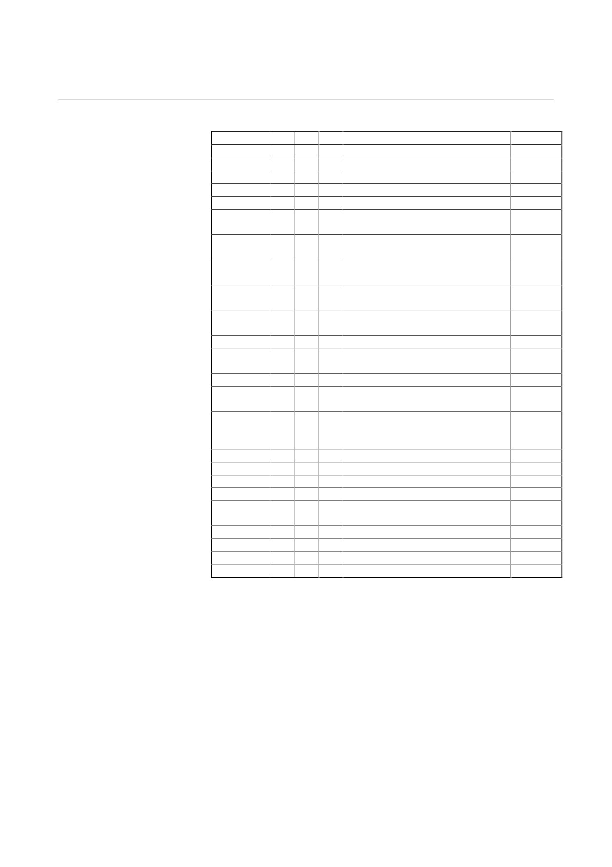
2. ALARM NUMBERS AND
B-65165E/02
TROUBLESHOOTING
BRIEF DESCRIPTIONS
Alarm No.
SVM
SPM
PSM
Description
Remarks
751 (AL-33)
33
05
DC link precharge failure
3.4
751 (AL-34)
34
Parameter data out of specification
3.4
751 (AL-35)
35
Too large gear ratio specified
3.4
751 (AL-36)
36
Error counter overflow
3.4
751 (AL-37)
37
Speed detector parameter error
3.4
751 (AL-39)
39
Cs contouring control one-rotation
3.4
signal detection error
751 (AL-40)
40
Cs contouring control one-rotation
3.4
signal not detected
751 (AL-41)
41
Position coder one-rotation signal
3.4
detection error
751 (AL-42)
42
Position coder one-rotation signal not
3.4
detected
751 (AL-43)
43
Differential speed mode position coder
3.4
signal disconnected
751 (AL-44)
44
A/D conversion error
3.4
751 (AL-46)
46
Position coder one-rotation signal
3.4
detection error during thread cutting
751 (AL-47)
47
Position coder signal error
3.4
751 (AL-49)
49
Excessive differential speed conversion
3.4
result
751 (AL-50)
50
Excessive speed command computed
3.4
value during the synchronization control
of the spindle
751 (AL-51)
51
04
DC link undervoltage
3.4
751 (AL-52)
52
ITP signal error I
3.4
751 (AL-53)
53
ITP signal error II
3.4
751 (AL-54)
54
Overload current alarm
3.4
751 (AL-55)
55
Power line state error at spindle or
3.4
speed range switching
751 (AL-56)
56
Control circuit cooling fan stopped
3.4
751 (AL-57)
57
08
Excessive regenerated power
3.4
751 (AL-58)
58
03
PSM main circuit overload
3.4
751 (AL-59)
59
02
PSM cooling fan stopped
3.4
- 107 -
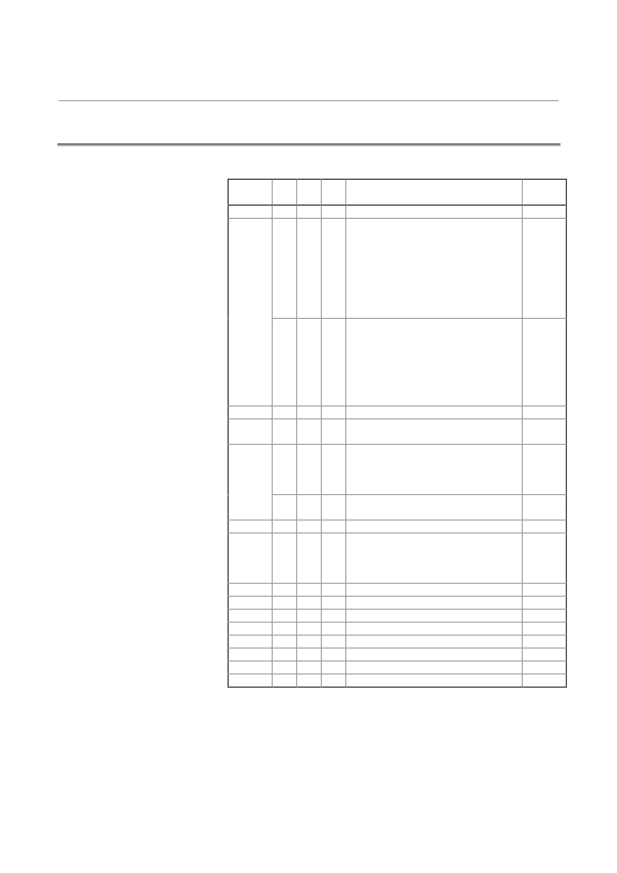
2. ALARM NUMBERS AND
BRIEF DESCRIPTIONS
TROUBLESHOOTING
B-65165E/02
2.4
FOR SERIES 15
Servo alarm
Alarm
SVM
SPM
PSM
Description
Remarks
No.
SV001
Soft thermal (OVC)
3.3.3
SV003
8
Abnormal current alarm
(L axis)
3.2
9
(M axis)
A
(N axis)
b
(L, M axis)
C
(M, N axis)
d
(L, N axis)
E
(L, M, N axis)
1
(PSM overcurrent + IPM alarm)
3.1
8.
IPM alarm
(L axis)
3.2
9.
(M axis)
A.
(N axis)
b.
(L, M axis)
C.
(M, N axis)
d.
(L, N axis)
E.
(L, M, N axis)
SV004
7
DC link overvoltage
3.1
SV005
5
Precharge alarm (Series 15-A)
3.1
(simultaneously with SV006)
SV006
2
Control power supply undervoltage alarm
3.1
5
DC link undervoltage alarm (SVM)
4
DC link undervoltage alarm (PSM)
6
Power supply state alarm
5
Precharge alarm (Series 15-A)
3.1
(simultaneously with SV005)
SV015
Feedback disconnected alarm
3.3.4
SV023
1
Fan stop alarm (SVM)
3.2
2
Fan stop alarm (PSM)
3.1
3
Overheat alarm (PSM)
Overheat alarm (motor)
3.3.5
SV027
Invalid servo parameter setting alarm
3.3.6
SV110
α pulse coder error alarm
3.3.7
SV114
Rotation speed data error alarm
3.3.7
SV115
Pulse coder communication error alarm
3.3.7
SV116
Precharge alarm (Series 15-B)
SV117
Current conversion error alarm
3.3.8
SV124
Excessive semi-full error alarm
3.3.8
SV129
Feedback mismatch alarm
3.3.8
- 108 -
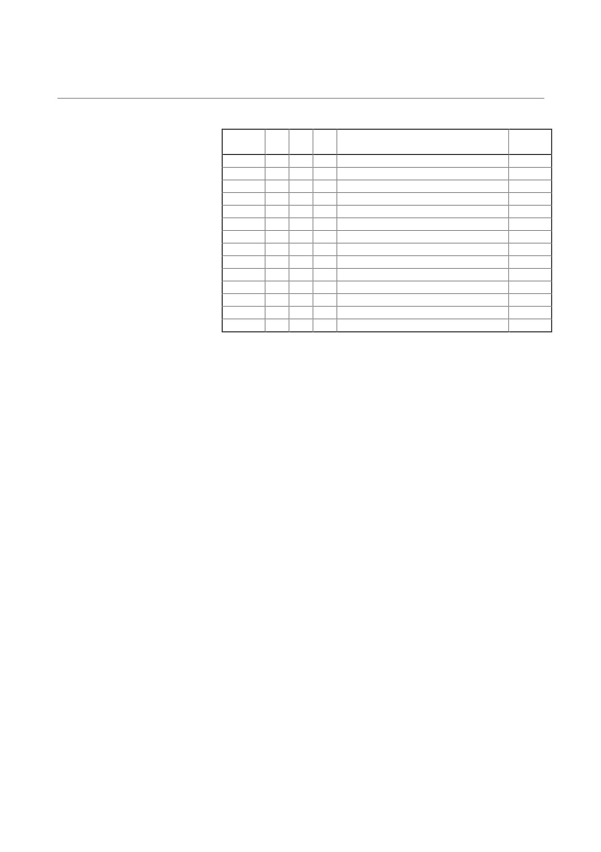
2. ALARM NUMBERS AND
B-65165E/02
TROUBLESHOOTING
BRIEF DESCRIPTIONS
Alarm
SVM
SPM
PSM
Description
Remarks
No.
SV323
Soft disconnection alarm
3.3.7
SV324
Hard disconnection alarm
3.3.7
SV325
Pulse coder error alarm (built-in)
3.3.7(1)
SV326
Pulse coder error alarm (built-in)
3.3.7(1)
SV327
Speed error (built-in)
3.3.7(1)
SV330
Serial communication error (built-in)
3.3.7(1)
SV331
Pulse coder error alarm (built-in)
3.3.7(2)
SV333
Pulse coder error alarm (separate linear)
3.3.7(2)
SV334
Pulse coder error alarm (separate rotary)
3.3.7(2)
SV335
Speed error (separate rotary)
3.3.7(2)
SV338
Separate detector alarm
3.3.7(2)
SV339
Serial communication error (separate)
3.3.7(3)
SV340
Hard disconnection alarm (separate)
3.3.4
SV351
Soft disconnection alarm (α pulse coder)
3.3.4
- 109 -
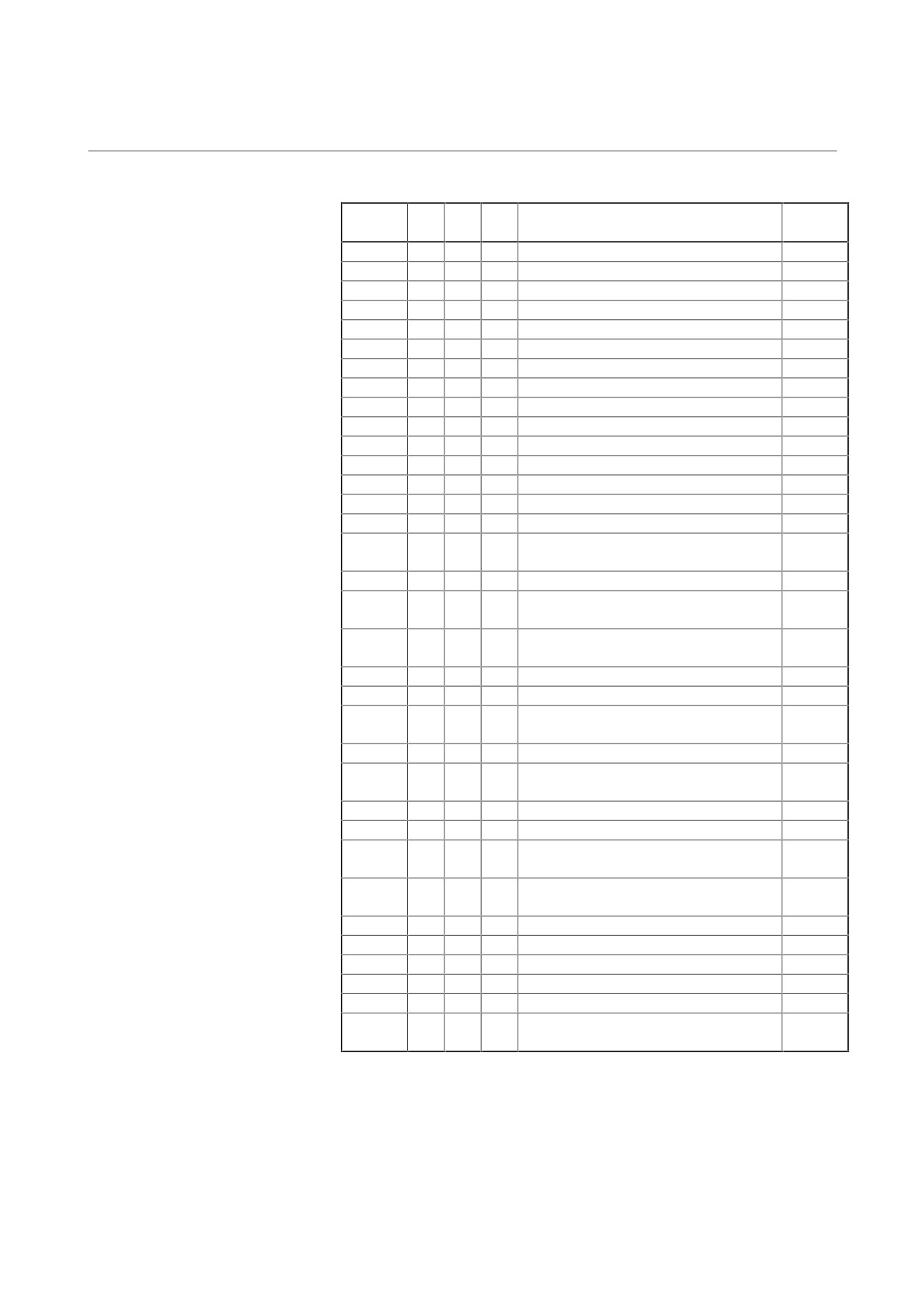
2. ALARM NUMBERS AND
BRIEF DESCRIPTIONS
TROUBLESHOOTING
B-65165E/02
Spindle alarm
Alarm
SVM
SPM
PSM
Description
Remarks
No.
OT300
A
Program ROM error
3.4
OT300
A0
Program ROM error
3.4
OT300
A1
Program RAM error
3.4
OT300
A2
Program RAM error
3.4
OT300
A3
SPM control circuit clock error
3.4
OT300
A4
SRAM parity error
3.4
OT301
01
Motor overheat
3.4
OT302
02
Excessive velocity error
3.4
OT399
03
DC link fuse blown
3.4
OT399
04
06
Power supply failure
3.4
OT307
07
Overspeed
3.4
OT309
09
Main circuit overload
3.4
OT311
11
07
DC link overvoltage
3.4
OT312
12
DC link overcurrent/IPM alarm
3.4
OT300
13
CPU internal data memory failure
3.4
OT399
15
Speed range switching and spindle
3.4
switching alarm
OT300
16
RAM error
3.4
OT300
19
Phase U current detector circuit excessive
3.4
offset
OT300
20
Phase V current detector circuit excessive
3.4
offset
OT300
24
Serial transfer data error
3.4
OT300
25
Serial data transfer stopped
3.4
OT326
26
Cs contouring control velocity detection
3.4
signal disconnected
OT327
27
Position coder signal disconnected
3.4
OT328
28
Cs contouring control position detection
3.4
signal disconnected
OT329
29
Short-period overload
3.4
OT330
30
01
PSM main circuit overcurrent
3.4
OT331
31
Speed detection signal disconnected and
3.4
motor lock alarm
OT300
32
Serial communication LSI internal RAM
3.4
error
OT333
33
05
DC link precharge failure
3.4
OT334
34
Parameter data out of specification
3.4
OT335
35
Too large gear ratio specified
3.4
OT336
36
Error counter overflow
3.4
OT399
37
Speed detector parameter error
3.4
OT399
39
Cs contouring control one-rotation signal
3.4
detection error
- 110 -
2. ALARM NUMBERS AND
B-65165E/02
TROUBLESHOOTING
BRIEF DESCRIPTIONS
Alarm
SVM
SPM
PSM
Description
Remarks
No.
OT399
40
Cs contour controling one-rotation signal
3.4
not detected
OT399
41
Position coder one-rotation signal
3.4
detection error
OT399
42
Position coder one-rotation signal not
3.4
detected
OT399
43
Differential speed mode position coder
3.4
signal disconnected
OT399
44
A/D conversion error
3.4
OT399
46
Position coder one-rotation signal
3.4
detection error during thread cutting
OT399
47
Position coder signal error
3.4
OT399
49
Excessive differential speed conversion
3.4
result
OT399
50
Excessive speed command computed
3.4
value during the synchronization control of
the spindle
OT399
51
04
DC link undervoltage
3.4
OT399
52
ITP signal error I
3.4
OT399
53
ITP signal error II
3.4
OT399
54
Overload current alarm
3.4
OT399
55
Power line state error at spindle or speed
3.4
range switching
OT399
56
Control circuit cooling fan stopped
3.4
OT399
57
08
Excessive regenerated power
3.4
OT399
58
03
PSM main circuit overload
3.4
OT399
59
02
PSM cooling fan stopped
3.4
- 111 -
2. ALARM NUMBERS AND
BRIEF DESCRIPTIONS
TROUBLESHOOTING
B-65165E/02
2.5
FOR SERIES 0-C
Servo alarm
Alarm
Diagnosis
SVM
SPM
PSM
Description
Remarks
No.
screen
309
Alarm 3
α pulse coder error alarm
3.3.7
Alarm 4
Pulse coder communication error alarm
400
OVL
1
Fan stopped alarm (SVM)
3.2
2
Fan stopped alarm (PSM)
3.1
3
Overheat alarm (PSM)
Overheat alarm (motor)
3.3.5
414
HVA
7
DC link overvoltage alarm
3.2
DCA & LVA
5
Precharge alarm
3.2
HCA
8
Abnormal current alarm
(L axis)
3.2
9
(M axis)
A
(N axis)
b
(L, M axis)
C
(M, N axis)
d
(L, N axis)
E
(L, M, N axis)
1
(PSM overcurrent + IPM alarm)
8.
IPM alarm
(L axis)
3.2
9.
(M axis)
A.
(N axis)
b.
(L, M axis)
C.
(M, N axis)
d.
(L, N axis)
E.
(L, M, N axis)
OVC
Soft thermal (OVC)
3.3.3
LVA
2
Control power supply undervoltage alarm
3.1
5
DC link undervoltage alarm (SVM)
4
DC link undervoltage alarm (PSM)
3.2
6
Power supply state alarm
416
FBA
Feedback disconnected alarm
3.3.4
417
PRM
Invalid servo parameter setting alarm
3.3.6
For
the
correspondence between the diagnosis screen
numbers and names, see the table below.
DGN No.
#7
#6
#5
#4
#3
#2
#1
#0
Alarm 1
720 to 723
OVL
LVA
OVC
HCA
HVA
DCA
FBA
OFA
Alarm 2
730 to 733
ALD
EXP
Alarm 3
760 to 763
CSA
BLA
PHA
RCA
BZA
CKA
SPH
Alarm 4
770 to 773
DTE
CRC
STB
PRM
- 112 -
2. ALARM NUMBERS AND
B-65165E/02
TROUBLESHOOTING
BRIEF DESCRIPTIONS
Spindle alarm
Alarm
SVM
SPM
PSM
Description
Remarks
No.
945
A
Program ROM error
3.4
945
A0
Program ROM error
3.4
945
A1
Program RAM error
3.4
945
A2
Program RAM error
3.4
945
A3
SPM control circuit clock error
3.4
945
A4
SRAM parity error
3.4
409
01
Motor overheat
3.4
409
02
Excessive velocity error
3.4
409
03
DC link fuse blown
3.4
409
04
06
Input power supply open phase and power
3.4
supply failure
409
07
Overspeed
3.4
409
09
Main circuit overload
3.4
409
11
07
DC link overvoltage
3.4
409
12
DC link overcurrent/IPM alarm
3.4
408
13
CPU internal data memory failure
3.4
409
15
Speed range switching and spindle
3.4
switching alarm
408
16
RAM error
3.4
408
19
Phase U current detector circuit excessive
3.4
offset
408
20
Phase V current detector circuit excessive
3.4
offset
945
24
Serial transfer data error
3.4
945
25
Serial data transfer stopped
3.4
409
26
Cs contouring control velocity detection
3.4
signal disconnected
409
27
Position coder signal disconnected
3.4
409
28
Cs contouring control position detection
3.4
signal disconnected
409
29
Short-period overload
3.4
409
30
01
PSM main circuit overcurrent
3.4
409
31
Speed detection signal disconnected and
3.4
motor lock alarm
408
32
Serial communication LSI internal RAM
3.4
error
409
33
05
DC link precharge failure
3.4
409
34
Parameter data out of specification
3.4
409
35
Too large gear ratio specified
3.4
409
36
Error counter overflow
3.4
409
37
Speed detector parameter error
3.4
409
39
Cs contouring control one-rotation signal
3.4
detection error
- 113 -
2. ALARM NUMBERS AND
BRIEF DESCRIPTIONS
TROUBLESHOOTING
B-65165E/02
Alarm
SVM
SPM
PSM
Description
Remarks
No.
409
40
Cs contouring control one-rotation signal
3.4
not detected
409
41
Position coder one-rotation signal
3.4
detection error
409
42
Position coder one-rotation signal not
3.4
detected
409
43
Differential speed mode position coder
3.4
signal disconnected
409
44
A/D conversion error
3.4
409
46
Position coder one-rotation signal
3.4
detection error during thread cutting
409
47
Position coder signal error
3.4
409
49
Excessive differential speed conversion
3.4
result
409
50
Excessive speed command computed
3.4
value during the synchronization control of
the spindle
409
51
04
DC link undervoltage
3.4
409
52
ITP signal error I
3.4
409
53
ITP signal error II
3.4
409
54
Overload current alarm
3.4
409
55
Power line state error at spindle or speed
3.4
range switching
409
56
Control circuit cooling fan stopped
3.4
409
57
08
Excessive regenerated power
3.4
409
58
03
PSM main circuit overload
3.4
409
59
02
PSM cooling fan stopped
3.4
- 114 -
3. TROUBLESHOOTING
B-65165E/02
TROUBLESHOOTING
AND ACTION
3
TROUBLESHOOTING AND ACTION
- 115 -
3. TROUBLESHOOTING
AND ACTION
TROUBLESHOOTING
B-65165E/02
3.1
POWER SUPPLY MODULE
3.1.1
Power Supply Module (PSM, PSM-HV)
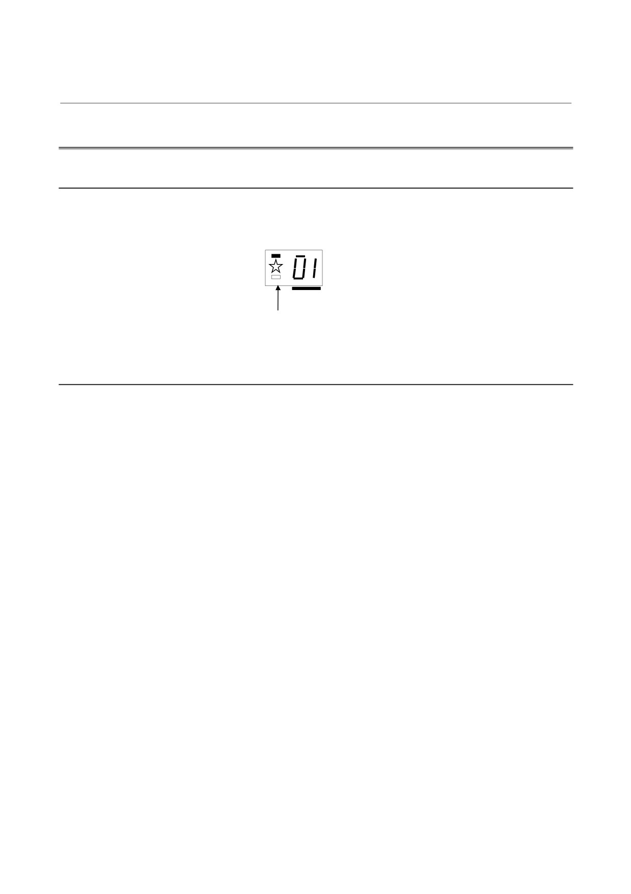
If an alarm occurs, in the STATUS display, the ALM LED lights red,
and the two-digit 7-segment display indicates an alarm code.
status
PIL
ALM
Indicates an alarm code (01 or above).
The ALM LED lights red.
3.1.1.1
Alarm code 01
For the PSM-5.5 to PSM-11
(1) Meaning
The main circuit power module (IPM) has detected an overload,
overcurrent, or control supply voltage decrease.
(2) Cause and troubleshooting
(a) Cooling fan failure
Check whether the cooling fan rotates normally.
→ Replace the cooling fan.
(b) Dust buildup
→ Clean the cooling system with a vacuum cleaner or
compressed air.
(c) Overload
→ Examine the operating conditions.
(d) Input supply voltage imbalance
→ Check the input power supply specification.
(e) The specification of the AC reactor does not match the PSM
in use.
→ Check the PSM and the specification of the AC reactor.
(f) IPM failure, or control supply voltage decrease of the power
module (IPM)
→ Replace the unit or IPM.
- 116 -
3. TROUBLESHOOTING
B-65165E/02
TROUBLESHOOTING
AND ACTION
For PSM-15 to PSM-55, PSM-18HV to PSM-75HV
(1) Meaning
Overcurrent flowed into the input of the main circuit.
(2) Cause and troubleshooting
(a) Input supply voltage imbalance
→ Check the input power supply specification.
(b) The specification of the AC reactor does not match the PSM
in use.
→ Check the PSM and the specification of the AC reactor.
(c) IGBT defective
→ Replace IGBT.
3.1.1.2 Alarm code 02
(1) Meaning
(a) A cooling fan for the control circuit has stopped.
(b) The control supply voltage has dropped.
(2) Cause and troubleshooting
(a) Cooling fan broken
Check whether the cooling fan rotates normally.
→ Replace it.
(b) Input voltage decrease
→ Check the power supply.
3.1.1.3 Alarm code 03
(1) Meaning
The temperature of the main circuit heat sink has risen
abnormally.
(2) Cause and troubleshooting
(a) Cooling fan for the main circuit broken
Check whether the cooling fan for the main circuit rotates
normally.
→ Replace it.
(b) Dust accumulation
→ Clean the cooling system with a vacuum cleaner or the
factory air blower.
(c) Overload
→ Examine the operating conditions.
- 117 -
3. TROUBLESHOOTING
AND ACTION
TROUBLESHOOTING
B-65165E/02
3.1.1.4 Alarm code 04
(1) Meaning
In the main circuit, the DC voltage (DC link) has dropped.
(2) Cause and troubleshooting
(a) A small power dip has occurred.
→ Check the power supply.
(b) Low input power supply voltage
→ Check the power supply specification.
(c) The main circuit power supply may have been switched off
with an emergency stop state released.
→ Check the sequence.
3.1.1.5 Alarm code 05
(1) Meaning
(a) The input power supply is abnormal (open phase).
(b) The main circuit capacitor was not recharged within the
specified time.
(2) Cause and troubleshooting
(a) The input power supply has an open phase.
→ Check the connection.
(b) Too many SVM and/or SPM units are connected.
→ Check the specification of the PSM.
(c) The DC link is short-circuited.
→ Check the connection.
(d) The recharge current limiting resistor is defective.
→ Replace the unit.
3.1.1.6 Alarm code 06
(1) Meaning
The input power supply is abnormal (open phase).
(2) Cause and troubleshooting
(a) The input power supply has an open phase.
→ Check the connection.
- 118 -
3. TROUBLESHOOTING
B-65165E/02
TROUBLESHOOTING
AND ACTION
3.1.1.7 Alarm code 07
(1) Meaning
In the main circuit, the DC voltage at the DC link is abnormally
high.
(2) Cause and troubleshooting
(a) Excessive regenerated power
Regeneration is impossible. The PSM does not have a
sufficient capacity.
→ Check the specification of the PSM.
(b) The output impedance of the AC power source is too high.
→ Check the power source output impedance.
(Normal if the voltage variation at maximum output time is
within 7%)
(c) Regeneration circuit failure
→ Replace the unit.
(d) The main circuit power supply may have been switched off
with an emergency stop state released.
→ Check the sequence.
3.1.2
Power Supply Module (PSMV)
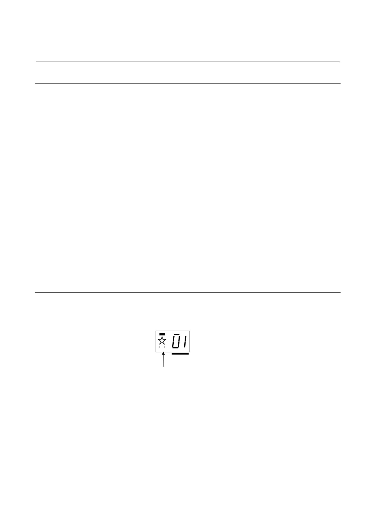
If an alarm occurs, in the STATUS display, the ALM LED lights red,
and the two-digit 7-segment display indicates an alarm code.
status
PIL
ALM
Indicates an alarm code (01 or above).
The ALM LED lights red.
- 119 -
3. TROUBLESHOOTING
AND ACTION
TROUBLESHOOTING
B-65165E/02
3.1.2.1 Alarm code 01
(1) Meaning
Overcurrent flowed into the DC link of the main circuit.
(2) Cause and troubleshooting
(a) Thyristor or IGBT failure
→ Replace the thyristor or IGBT.
(b) DC link short-circuit
→ Check the connection.
(c) The specification of the AC reactor does not match the
PSMV in use.
→ Check the PSMV and the specification of the AC
reactor.
3.1.2.2 Alarm code 02
(1) Meaning
A cooling fan for the control circuit has stopped.
(2) Cause and troubleshooting
(a) Cooling fan for the control circuit broken
Check whether the cooling fan for the control circuit rotates
normally.
→ Replace it.
3.1.2.3 Alarm code 03
(1) Meaning
The temperature of the main circuit heat sink has risen
abnormally.
(2) Cause and troubleshooting
(a) Cooling fan for the main circuit broken
Check whether the cooling fan for the main circuit rotates
normally.
→ Replace it.
(b) Dust accumulation
→ Clean the cooling system with a vacuum cleaner or the
factory air blower.
(c) Overload
→ Examine the operating conditions.
- 120 -
3. TROUBLESHOOTING
B-65165E/02
TROUBLESHOOTING
AND ACTION
3.1.2.4 Alarm code 04
(1) Meaning
In the main circuit, the DC voltage (DC link) has dropped.
(2) Cause and troubleshooting
(a) Low input power supply voltage
→ Check the power supply.
3.1.2.5 Alarm code 05
(1) Meaning
The main circuit capacitor was not recharged within the specified
time.
(2) Cause and troubleshooting
(a) Too many SVM and/or SPM units are connected.
→ Check the specification of the PSMV.
3.1.2.6 Alarm code 06
(1) Meaning
(a) The main circuit supply voltage is not fed.
(b) Two or more input fuses of the AC reactor unit have blown.
Note) This alarm is also output when a momentary power failure
occurs.
(2) Cause and troubleshooting
(a) The input supply voltage is not fed to the main circuit.
→ Check the connection.
(b) Two or more input fuses of the AC reactor unit have blown.
→ Replace the fuses.
3.1.2.7 Alarm code 16
(1) Meaning
(a) The main circuit power supply has an open phase.
(b) One input fuse of the AC reactor unit has blown.
(2) Cause and troubleshooting
(a) The main circuit power supply has an open phase.
→ Check the connection.
(b) One input fuse of the AC reactor unit has blown.
→ Replace the fuse.
- 121 -
3. TROUBLESHOOTING
AND ACTION
TROUBLESHOOTING
B-65165E/02
3.1.2.8 Alarm code 26
(1) Meaning
The frequency of the main circuit input power supply is abnormal.
(2) Cause and troubleshooting
(a) Input power supply frequency error
→ Check the input power supply specification (50/60 Hz
±1 Hz).
3.1.2.9 Alarm code 36
(1) Meaning
The input power supply of the main circuit has an imbalance.
(2) Cause and troubleshooting
(a) The input supply voltage has an imbalance of 5% or more.
→ Check the input power supply specification.
3.1.2.10 Alarm code 46
(1) Meaning
When the magnetic contactor is turned on, the phase sequence of
the power supply cannot be determined.
(2) Cause and troubleshooting
(a) Input power supply error
→ Check the input power supply specification.
3.1.2.11 Alarm code 07
(1) Meaning
In the main circuit, the DC voltage at the DC link is abnormally
high.
(2) Cause and troubleshooting
(a) Excessive regenerated power
The PSMV does not have a sufficient capacity.
→ Check the specification of the PSMV.
(b) The output impedance of the AC power source is too high.
→ Check the power source output impedance.
(Normal if the voltage variation at maximum output time is
within 7%)
(c) Regeneration circuit failure
→ Replace the unit.
- 122 -
3. TROUBLESHOOTING
B-65165E/02
TROUBLESHOOTING
AND ACTION
3.1.2.12 Alarm code 17
(1) Meaning
In the main circuit, the voltage at the DC link is abnormally high.
A fuse of the AC reactor unit may have blown.
(2) Cause and troubleshooting
(a) An input fuse of the AC reactor unit has blown.
→ Replace the fuse.
(b) Regeneration circuit failure
→ Replace the unit.
3.1.2.13 Alarm code 08
(1) Meaning
The offset of the current detection circuit of the main circuit DC
link is excessive.
(2) Cause and troubleshooting
(a) The current detection circuit of the main circuit DC link
malfunctions.
→ Replace the power printed wiring board.
(b) The control printed circuit board or A/D converter is faulty.
→ Replace the control printed circuit board.
3.1.2.14 Alarm code 18
(1) Meaning
An error occurred in internal parameter data transfer processing.
(2) Cause and troubleshooting
(a) The control printed circuit board is faulty.
→ Replace the control printed circuit board.
- 123 -
3. TROUBLESHOOTING
AND ACTION
TROUBLESHOOTING
B-65165E/02
3.1.2.15 Alarm code A0
(1) Meaning
(a) No ROM is installed.
(b) The ROM is faulty.
(2) Cause and troubleshooting
(a) The ROM is not installed correctly, or no ROM is installed.
Check if the ROM is removed from the socket or if a bent
lead has caused a bad contact.
→ Install the ROM correctly.
(b) ROM specification error
Check the software version stamped on the ROM.
→ Install a specified ROM correctly.
(c) Control printed circuit board failure
→ Replace the control printed circuit board.
3.1.2.16 Alarm code A1
(1) Meaning
The RAM is faulty.
(2) Cause and troubleshooting
(a) The control printed circuit board is faulty.
→ Replace the control printed circuit board.
3.1.2.17 Alarm code A2
(1) Meaning
A program is not operating normally.
(2) Cause and troubleshooting
(a) The control printed circuit board is faulty.
→ Replace the control printed circuit board.
- 124 -

3. TROUBLESHOOTING
B-65165E/02
TROUBLESHOOTING
AND ACTION
3.1.3
Power Supply Module (PSMR)
When an alarm is issued, the one-digit 7-segment LED indicates an
alarm code.
Indicates an alarm code (02 or above).
3.1.3.1 Alarm code 2
(1) Meaning
A cooling fan for the control circuit has stopped.
(2) Cause and troubleshooting
(a) Cooling fan for the control circuit broken
Check whether the cooling fan for the control circuit rotates
normally.
→ Replace it.
3.1.3.2 Alarm code 4
(1) Meaning
In the main circuit, the DC voltage (DC link) has dropped.
(2) Cause and troubleshooting
(a) A small power dip has occurred.
→ Check the power supply.
(b) Low input power supply voltage
→ Check the power supply specification.
(c) The main circuit power supply may have been switched off
with an emergency stop state released.
→ Check the sequence.
- 125 -
3. TROUBLESHOOTING
AND ACTION
TROUBLESHOOTING
B-65165E/02
3.1.3.3 Alarm code 5
(1) Meaning
(a) The input power supply is abnormal (open phase).
(b) The main circuit capacitor was not recharged within the
specified time.
(2) Cause and troubleshooting
(a) The input power supply has an open phase.
→ Check the connection.
(b) Too many SVM and/or SPM units are connected.
→ Check the specification of the PSM.
(c) The DC link is short-circuited.
→ Check the connection.
(d) The recharge current limiting resistor is defective.
→ Replace the unit.
3.1.3.4 Alarm code 6
(1) Meaning
The control supply voltage has dropped.
(2) Cause and troubleshooting
(a) Input voltage decrease
→ Check the power supply.
3.1.3.5 Alarm code 7
(1) Meaning
In the main circuit, the DC voltage at the DC link is abnormally
high.
(2) Cause and troubleshooting
(a) Excessive regenerated power
The PSMR does not have a sufficient capacity.
→ Check the specification of the PSMR.
(b) Regeneration circuit failure
→ Replace the unit.
- 126 -
3. TROUBLESHOOTING
B-65165E/02
TROUBLESHOOTING
AND ACTION
3.1.3.6 Alarm code 8
(1) Meaning
(a) The regenerative discharge unit is heated.
(b) Regenerated power is excessive.
(2) Cause and troubleshooting
(a) The regenerative resistance capacity is insufficient.
→ Check the specification of the regenerative resistance.
(b) Excessive regenerated power
→ Decrease the frequency of acceleration/deceleration
during operation.
(c) The cooling fan of the regenerative discharge unit is faulty.
→ Check the rotation state of the cooling fan.
- 127 -