FANUC Alpha Series Motors and Modular Drives. Maintenance Manual (GFZ-65165E/02) - page 3
4. CONFIRMATION OF
THE OPERATION
START-UP PROCEDURE
B-65165E/02
4.1.3
Checking The Status Leds
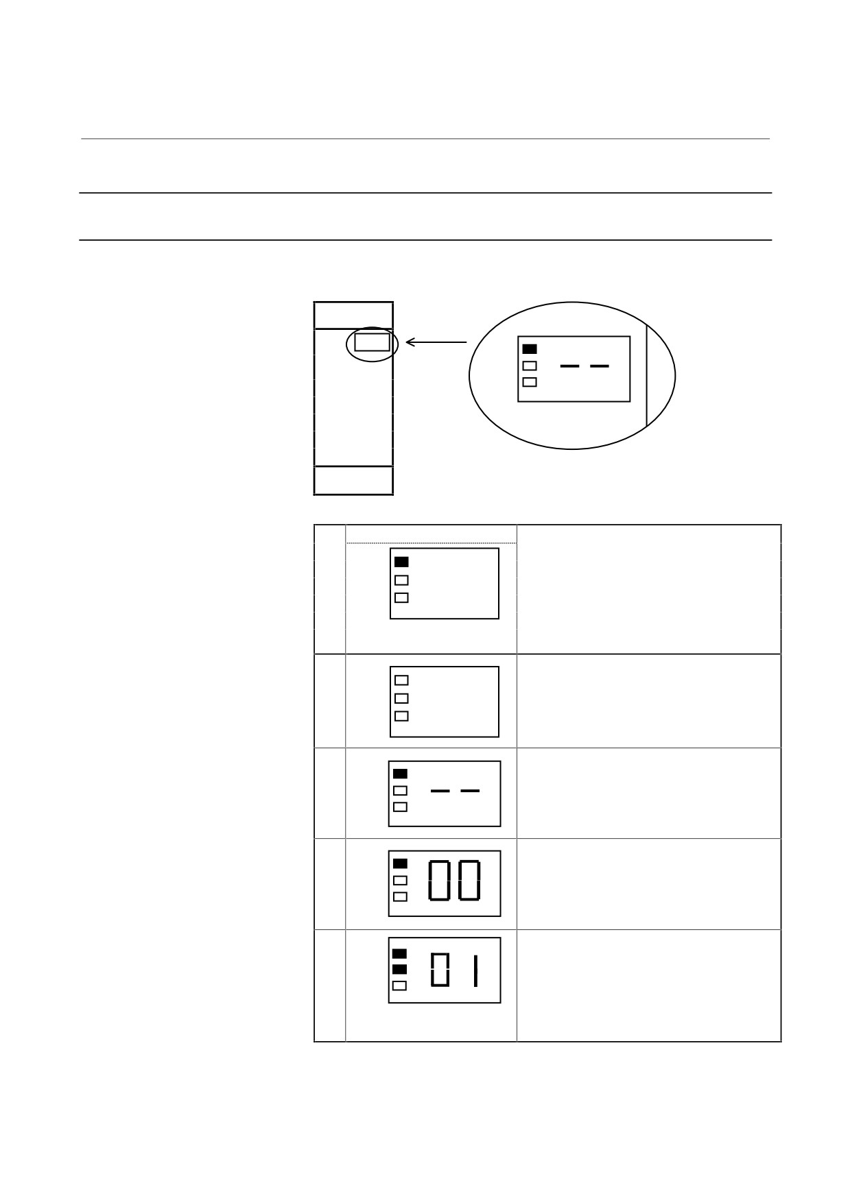
4.1.3.1 PSM, PSM-HV, and PSMV-HV
Position of the STATUS LEDs
STATUS
PIL
ALM
STATUS LEDs
On
Off
No.
Description
The LED that is on is
indicated in black.
1
The PIL LED (power ON indicator) is off.
PIL
Control power has not been supplied.
ALM
The control power circuit is defective. See
Section 4.1.2.
2
PSM not ready
PIL
The main circuit is not supplied with power
ALM
(MCC OFF).
Emergency stop state
3
PSM ready
PIL
The main circuit is supplied with power
ALM
(MCC ON).
The PSM is operable.
4
Alarm state
PIL
The PSM is not operable.
ALM
See Section 3.1 of Part II.
Alarm code 01 or above is
indicated.
- 36 -
4. CONFIRMATION OF
B-65165E/02
START-UP PROCEDURE
THE OPERATION
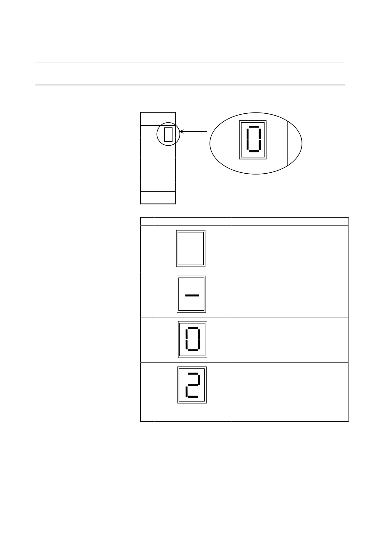
4.1.3.2 PSMR
Position of the STATUS LEDs
STATUS
No.
STATUS LEDs
Description
1
The STATUS display LED is off.
Control power has not been supplied.
The control power circuit is defective. See
Section 4.1.2.
2
PSMR not ready
The main circuit is not supplied with power
(MCC OFF).
Emergency stop state
3
PSMR ready
The main circuit is supplied with power
(MCC ON).
The PSMR is operable.
4
Alarm state
The PSMR is not operable.
See Section 3.1.3 of Part II.
Alarm code 02 or above is
indicated.
- 37 -

4. CONFIRMATION OF
THE OPERATION
START-UP PROCEDURE
B-65165E/02
4.1.4
The PIL LED (power ON indicator) Is Off.
Table 4.1.4 Check method and action
No.
Cause of trouble
Check method
Action
1
AC power for the
Check that power is
control circuit not
connected to connector
supplied
CX1A.
2
Blown fuse in the
Check whether F1 or F2
(1)
If the AC power input
control circuit
has blown. (PSM, PSM-
for control is
HV)
connected to
Check whether FU1 or FU2
connector CX1B by
has blown. (PSMV-HV)
mistake, F2 (FU2) may
For details on how to
blow. Connect the AC
replace fuses, see Chapter
power input to CX1A.
4 of Part II.
(2)
Replace the fuse. If
the fuse blows again
after the replacement,
replace the printed
circuit board.
3
Incorrect wiring
Check whether the 24-V
power output is short-
circuited and whether a
load exceeding the rating is
connected.
4
Faulty power
The power-on LED indicator
(1)
Replace the PSM.
supply circuit on
PIL operates on the +5-V
(2)
Replace the printed
the printed circuit
power supply. See
circuit board, driver
board
Subsection 4.1.2 to check
board, or power
the control power voltage.
distribution board.
- 38 -
4. CONFIRMATION OF
B-65165E/02
START-UP PROCEDURE
THE OPERATION
4.1.5
Checking For What Keeps The Mcc From Being Switched On
(1) The system is still in an emergency stop status.
→ Check the connection to make sure that the emergency stop
signal connected to the PSM connector CX4 and the
emergency stop signal (such as *ESP) input to the CNC are
both released.
(2) There is a connector problem.
(a) No terminating connector is attached.
→ Check whether a terminating connector is attached to
JX1B of the SVM or SPM at the end of the connection
chain.
(b) The interface cable between JX1B of the power supply
module and JX1A of the SVM or SPM is defective.
→ Check whether the interface cable is faulty.
(3) The power for driving the magnetic contactor is not supplied.
→ Check the voltage across the both ends of the coil of the
magnetic contactor.
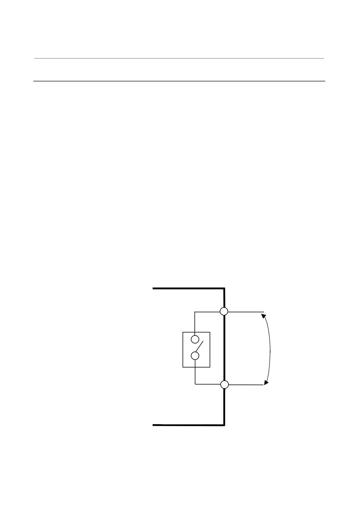
(4) The relay for driving the magnetic contactor is defective.
→ Check that a circuit between pins <1> and <3> of connector
CX3 is closed and opened.
CX3-<1>
Make sure that the contact
MCC driving relay
is closed and opened.
CX3-<3>
PSM, PSMR
PSM-HV
PSMV-HV
- 39 -
4. CONFIRMATION OF
THE OPERATION
START-UP PROCEDURE
B-65165E/02
4.2
SERVO AMPLIFIER MODULE
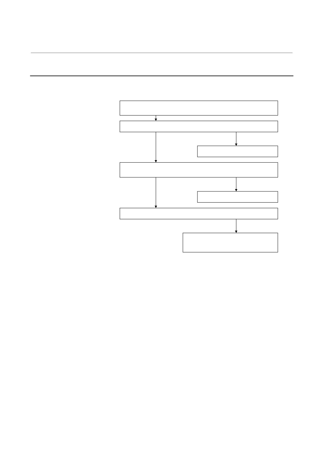
Check each item according to the procedure described below.
1. Check the connection, and supply control power (200 VAC) to the power
supply module.
2. Check the STATUS LEDs. See Section 4.2.2.
Alarm occurs.
See Section 3.2 of Part II.
3. Check the CNC parameters (including servo parameters), and reset
emergency stop state.
Alarm occurs.
See Section 3.2 of Part II.
4. Check the operation of the servo motor.
Abnormal operation
Refer to the FANUC AC SERVO MOTOR
α series Parameter Manual (B-65150E).
- 40 -
4. CONFIRMATION OF
B-65165E/02
START-UP PROCEDURE
THE OPERATION
4.2.1
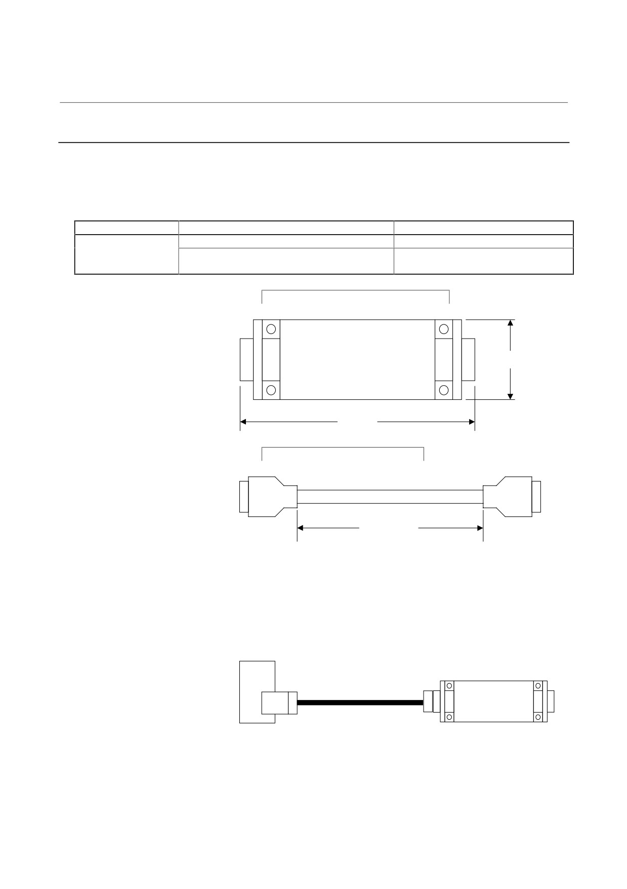
Check Pin Board
Use of the check pin board allows you to observe the signals inside the
servo amplifier.
(1) Specifications
Order specification
Component
Remarks
A06B-6071-K290
Printed circuit board: A20B-1005-0340
Printed circuit board with check pins
Cable
: A660-2042-T031#L200R0
20-conductor cable with a one-to-one
correspondence. Length: 200 mm
Printed circuit board: A20B-1005-0340
A20B-1005-0340
• <5>
• <4>
• <3>
• <2>
• <1>
• <10>
• <9>
• <8>
• <7>
• <6>
• <15> • <14>
• <13>
• <12>
• <11>
34 mm
• <20>
• <19>
• <18>
• <17>
• <16>
CN1
CN2
100 mm
Cable: A660-2042-T031#L200R0
Approx. 200 mm
CN1 and CN2 are wired with a one-to-one correspondence.
The connector pin numbers correspond to the check pin numbers.
(2) Connection
Attach the cable to connector JX5 that is located on the front of
the SVM.
SVM
A20B-1005-0340
JX5
CN2
CN1
- 41 -
4. CONFIRMATION OF
THE OPERATION
START-UP PROCEDURE
B-65165E/02
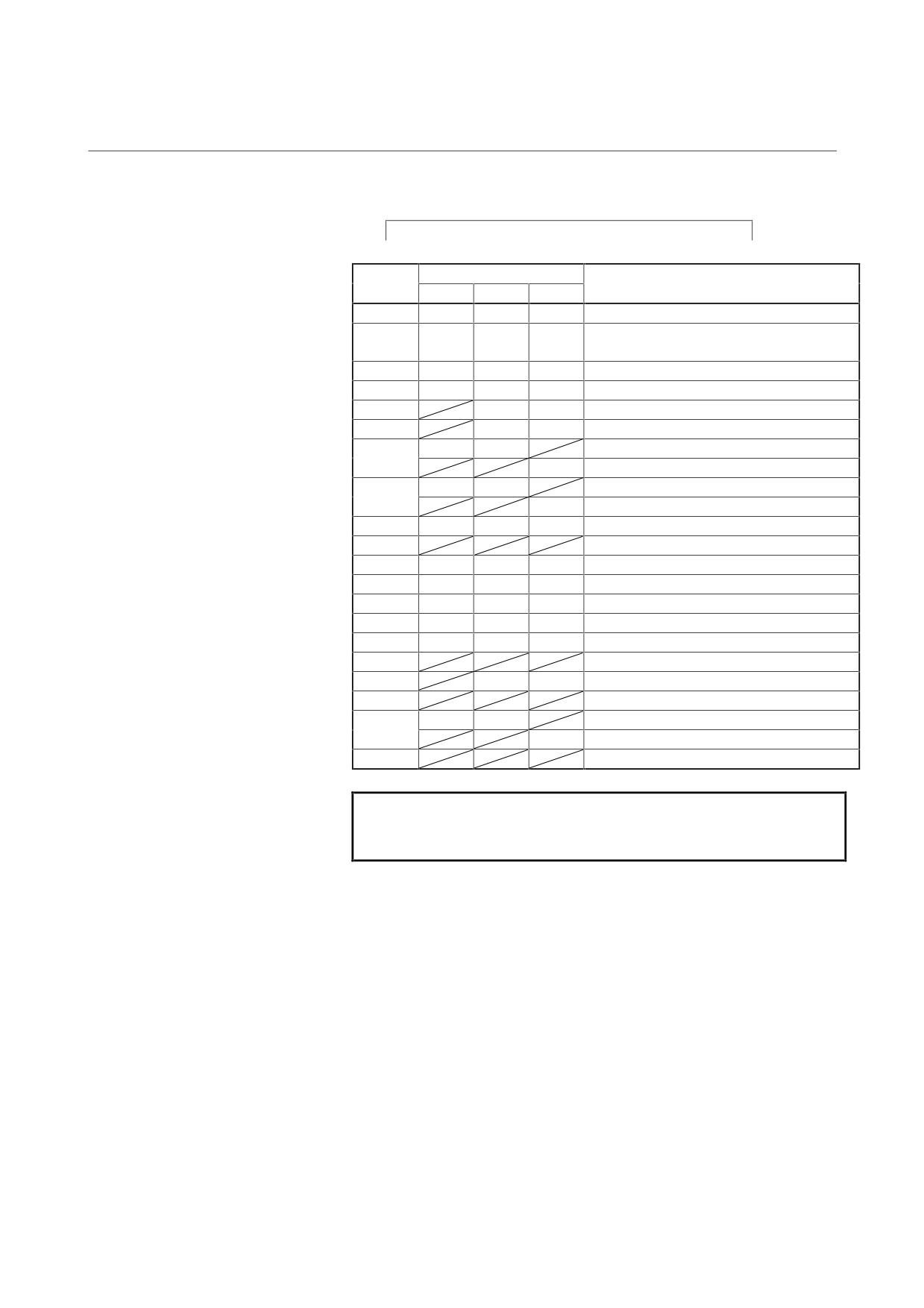
(3) Signal output
SVM designed for operation with the FSSB interface
Signal name
Pin No.
Remarks
SVM1
SVM2
SVM3
<1>
CLR
CLR
CLR
Clear signal of the control circuit(Note)
<2>
+3.3V
+3.3V
+3.3V
+3.3-V power (Variations in voltage level
within ±5% are regarded as normal.)
<3>
IRL
IRL
IRL
Phase R motor current for the L axis
<4>
ISL
ISL
ISL
Phase S motor current for the L axis
<5>
IRM
IRM
Phase R motor current for the M axis
<6>
ISM
ISM
Phase S motor current for the M axis
<7>
0V
0V
Reference voltage
IRN
Phase R motor current for the N axis
<8>
0V
0V
Reference voltage
ISN
Phase S motor current for the N axis
<9>
0V
0V
0V
Reference voltage
<10>
<11>
+24V
+24V
+24V
+24-V power
<12>
+15V
+15V
+15V
+15-V power
<13>
-15V
-15V
-15V
-15-V power
<14>
+5V
+5V
+5V
+5-V power
<15>
ITL
ITL
ITL
Phase T motor current for the L axis
<16>
<17>
ITM
ITM
Phase T motor current for the M axis
<18>
<19>
0V
0V
Reference voltage
ITN
Phase T motor current for the N axis
<20>
NOTE
Do not touch the clear signal of the control circuit;
otherwise, the servo amplifier may malfunction.
- 42 -
4. CONFIRMATION OF
B-65165E/02
START-UP PROCEDURE
THE OPERATION
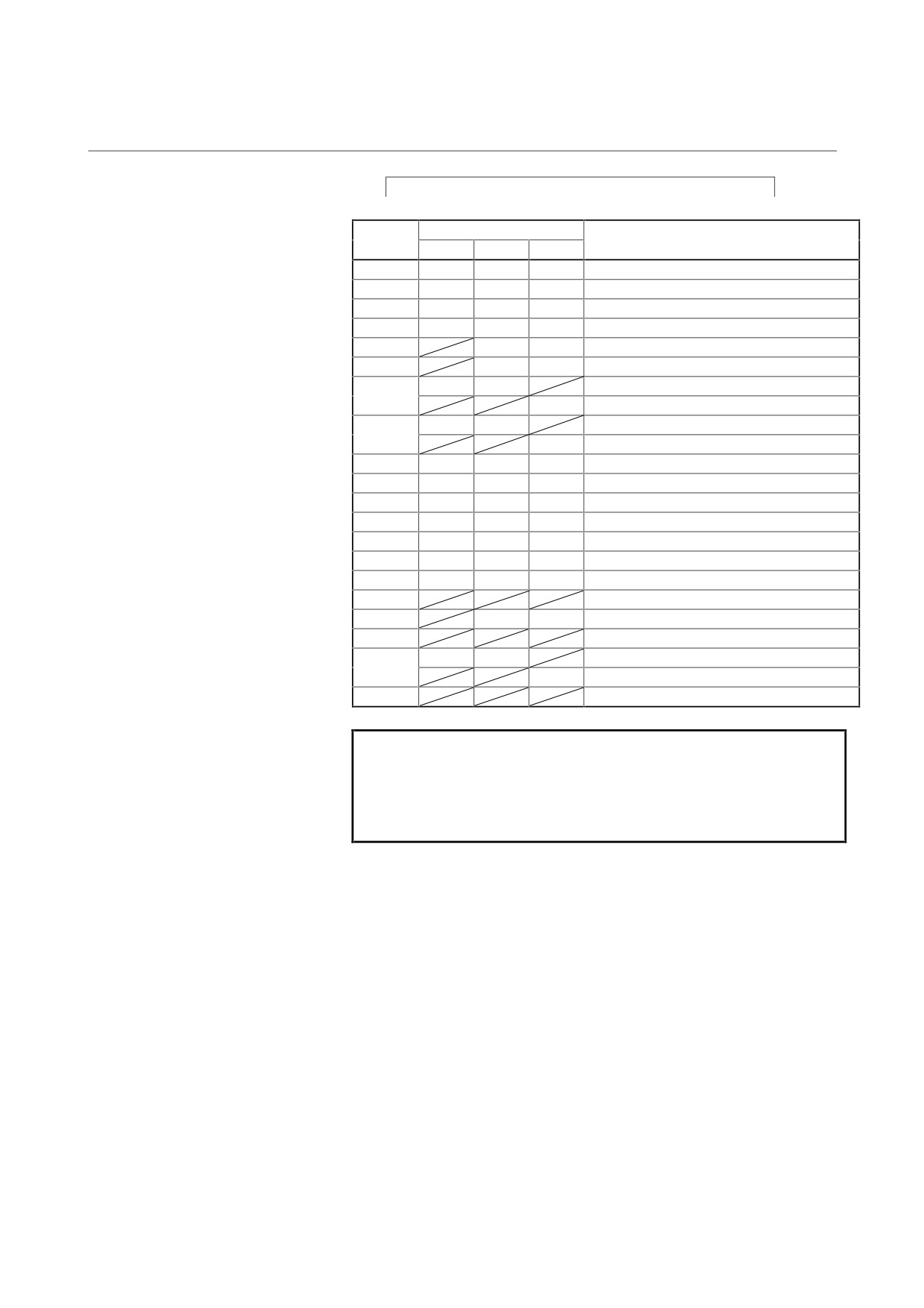
SVM designed for operation with the type A/B interface
Signal name
Pin No.
Remarks
SVM1
SVM2
SVM3
<1>
CLR
CLR
CLR
Clear signal of the control circuit(Note 1)
<2>
0V
0V
0V
Reference voltage
<3>
IRL
IRL
IRL
Phase R motor current for the L axis
<4>
ISL
ISL
ISL
Phase S motor current for the L axis
<5>
IRM
IRM
Phase R motor current for the M axis
<6>
ISM
ISM
Phase S motor current for the M axis
<7>
0V
0V
Reference voltage
IRN
Phase R motor current for the N axis
<8>
0V
0V
Reference voltage
ISN
Phase S motor current for the N axis
<9>
0V
0V
0V
Reference voltage
<10>
0V
0V
0V
Reference voltage
<11>
+24V
+24V
+24V
+24-V power
<12>
+15V
+15V
+15V
+15-V power
<13>
-15V
-15V
-15V
-15-V power
<14>
+5V
+5V
+5V
+5-V power
<15>
ITL
ITL
ITL
Phase T motor current for the L axis
<16>
<17>
ITM
ITM
Phase T motor current for the M axis
<18>
<19>
0V
0V
Reference voltage
ITN
Phase T motor current for the N axis
<20>
NOTE
1
Do not touch the clear signal of the control circuit;
otherwise, the servo amplifier may malfunction.
2
Part of the signal may not be output depending on
the revision of the printed circuit board.
- 43 -
4. CONFIRMATION OF
THE OPERATION
START-UP PROCEDURE
B-65165E/02
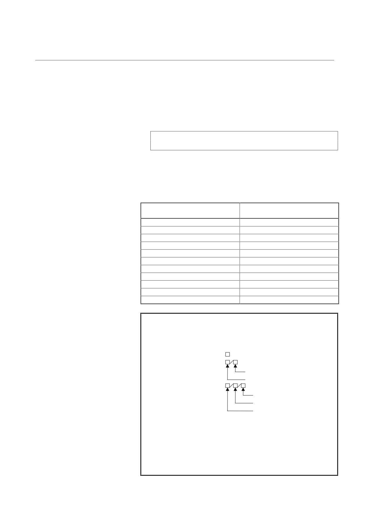
(4) Observing the motor current
You can observe an instantaneous motor current value by
observing the voltage across a reference voltage (0 V) check pin
and a motor current check pin with an oscilloscope. Note that you
cannot use a device such as a multimeter to observe correct
values.
(Instantaneous motor current value) = (voltage at motor current
check pin) × (factor for calculating motor current)
Calculation example:
When the voltage at a motor current check pin is 3.2 V, and
the factor for calculation is 3 A/V:
Actual motor current (A) = 3.2 V × 3 A/V = 9.6 A
Limit of instantaneous motor
Factor for calculating motor
current value [A](Note 1)
current [A/V](Note 2)
2
0.5
4
1
12
3
20
5
40
10
60
15
80
20
130
32.5
240
60
320
80
360
90
NOTE
1
Limit of instantaneous motor current value
Values in in servo amplifier names indicate the
limits of instantaneous motor current values.
Single-axis amplifier: SVM1-
Double-axis amplifier: SVM2-
M axis
L axis
Triple-axis amplifier: SVM3-
N axis
M axis
L axis
2
The factor for calculating the motor current of an
SVM not listed in the above table can be obtained
from the model name of the servo amplifier as
follows:
Factor for calculating the motor current = (limit of
instantaneous motor current value) ÷ 4 V
- 44 -

4. CONFIRMATION OF
B-65165E/02
START-UP PROCEDURE
THE OPERATION
(4) Checking the power supply voltage
You can measure the voltage across a reference voltage (0V)
check pin and a power check pin with a multimeter, oscilloscope,
or the like to observe the power supply voltage for the control
circuit inside the servo amplifier. If the measured voltage is
within ±5% relative to the nominal voltage, the measured voltage
can be considered to be acceptable.
Check pin
Nominal voltage
+3.3V
+3.3-V power
+24V
+24-V power
+15V
+15-V power
-15V
-15-V power
+5V
+5-V power
- 45 -
4. CONFIRMATION OF
THE OPERATION
START-UP PROCEDURE
B-65165E/02
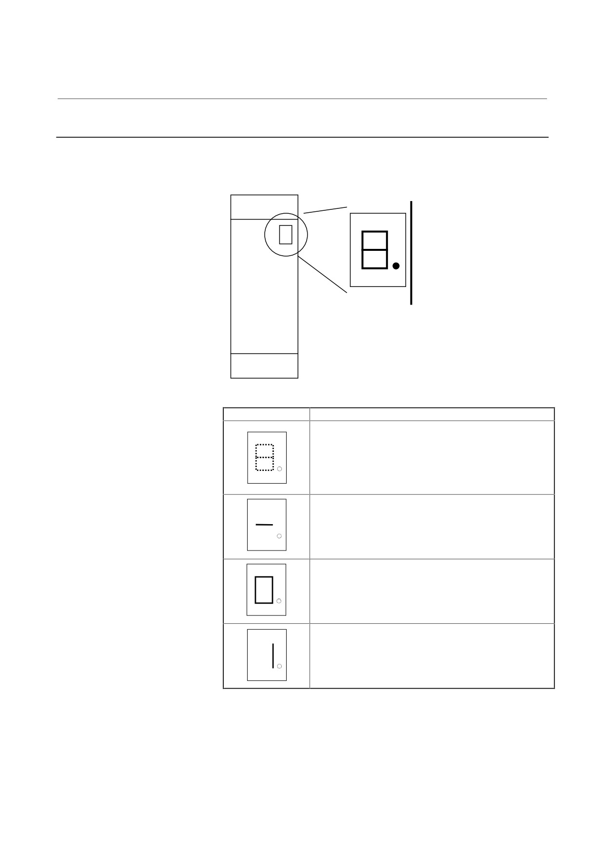
4.2.2
Checking The STATUS Display
The STATUS display (a 7-segment LED) on the front of the SVM
indicates the operation status.
STATUS
STATUS display
Description
• The STATUS display LED is not on.
<1> Power is not turned on.
<2> Poor cable connection
Check the cable.
<3> The servo amplifier is defective.
Replace the fuse (F1) or servo amplifier.
• The control power supply is waiting for a ready signal.
• The servo amplifier is ready to operate.
The servo motor is supplied with power.
• Alarm state
If an alarm is issued in the servo amplifier, a value other
than "0" and "-" is indicated on the STATUS display
LED. See Section 3.2 of Part II.
- 46 -
4. CONFIRMATION OF
B-65165E/02
START-UP PROCEDURE
THE OPERATION
4.2.3
VRDY-OFF Alarm Indicated on the CNC Screen
When the VRDY-OFF alarm is indicated on the CNC, check the items
listed below. In addition to these causes, there are other possible
causes of VRDY-OFF. If the problem still exists after the following
items are checked, contact your FANUC service representative.
(1)
Interface between modules
(a) Is a terminating dummy connector for the interface between
modules (JX1A, JX1B) attached to JX1B of the module (an
SVM or SPM) at the end of the connection chain?
(2)
Emergency stop signal (ESP)
(a) Has the emergency stop signal (connector: CX4) applied to
the PSM been released? Alternatively, is the signal
connected correctly?
(b) Is the emergency stop signal line (pin 3 of connectors CX2A
and CX2B) between the PSM and SVM or SPM connected
correctly?
(3)
MCON signal
(a) Has the ready command signal MCON been sent from the
CNC to SVM?
• Check for poor contact in the command cable between the
CNC and SVM.
• Use the servo check pin board to check the signal level.
(b) For the multi-axis amplifier, is the MCON signal sent to all
axes?
(4)
External MCC
(a) Is the external MCC connected correctly and is there any
problem in the external MCC itself?
(5)
Timing of turning on the power to the CNC (200 VAC, single
phase) and the PSM control power (200 VAC, single phase)
(a) Was the power to the CNC turned on at the same time when,
or after, the power for PSM control was turned on?
(6)
Is there an unused axis in a multi-axis amplifier?
(a) Is a dummy connector inserted in the amplifier?
(b) Are CNC parameters set correctly?
- 47 -
4. CONFIRMATION OF
THE OPERATION
START-UP PROCEDURE
B-65165E/02
4.2.4
Servo Check Board
The servo check board receives the digital value used for control inside
the digital servo as numerical data and converts it to an analog form.
For details on how to connect and use the servo check board, refer to
the following:
FANUC AC SERVO MOTOR α series Parameter Manual B-
65150E/04 or later editions
- 48 -
4. CONFIRMATION OF
B-65165E/02
START-UP PROCEDURE
THE OPERATION
4.3
SPINDLE AMPLIFIER MODULE
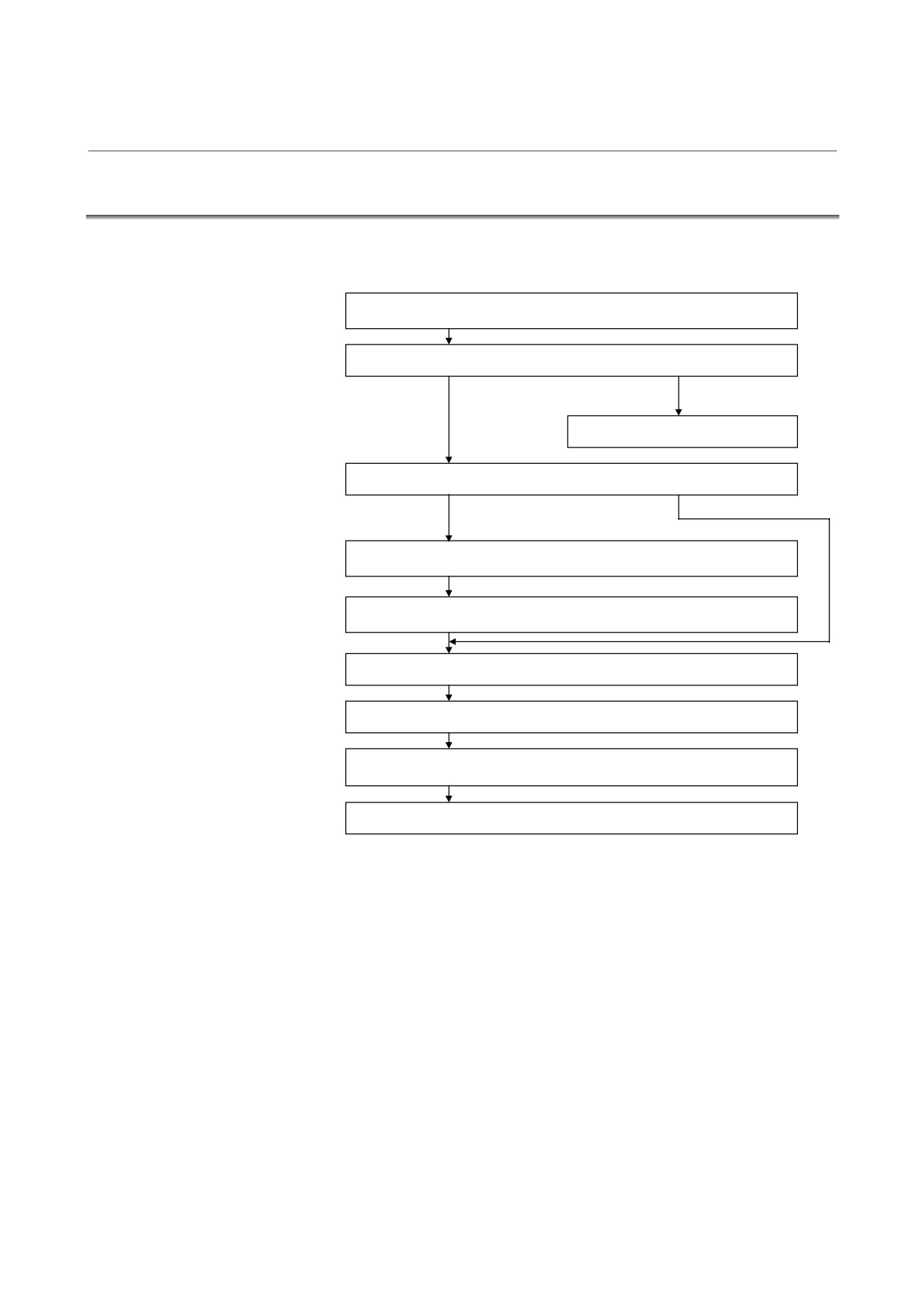
Check each item according to the procedure described below.
1. Supply control power (200 VAC) to the PSM, and turn on the power
to the CNC.
2. Check the STATUS display. See Subsection 4.3.1.
OK
Alarm issued.
See Section 3.4 of Part II.
3. Has the system been used with this connection status?
No
Yes
4. Prepare and check a PMC ladder. (The descriptions manual is
required.)
5. Set and check spindle-related parameters. (The parameter manual
is required.)
6. Check the waveform on the detector. See Subsection 4.3.4.
7. Release the system from the emergency stop state.
8. Make sure that the magnetic contactor for PSM input is turned on.
See Section 4.1.
9. Check the operation in normal operation mode (S command).
- 49 -
4. CONFIRMATION OF
THE OPERATION
START-UP PROCEDURE
B-65165E/02
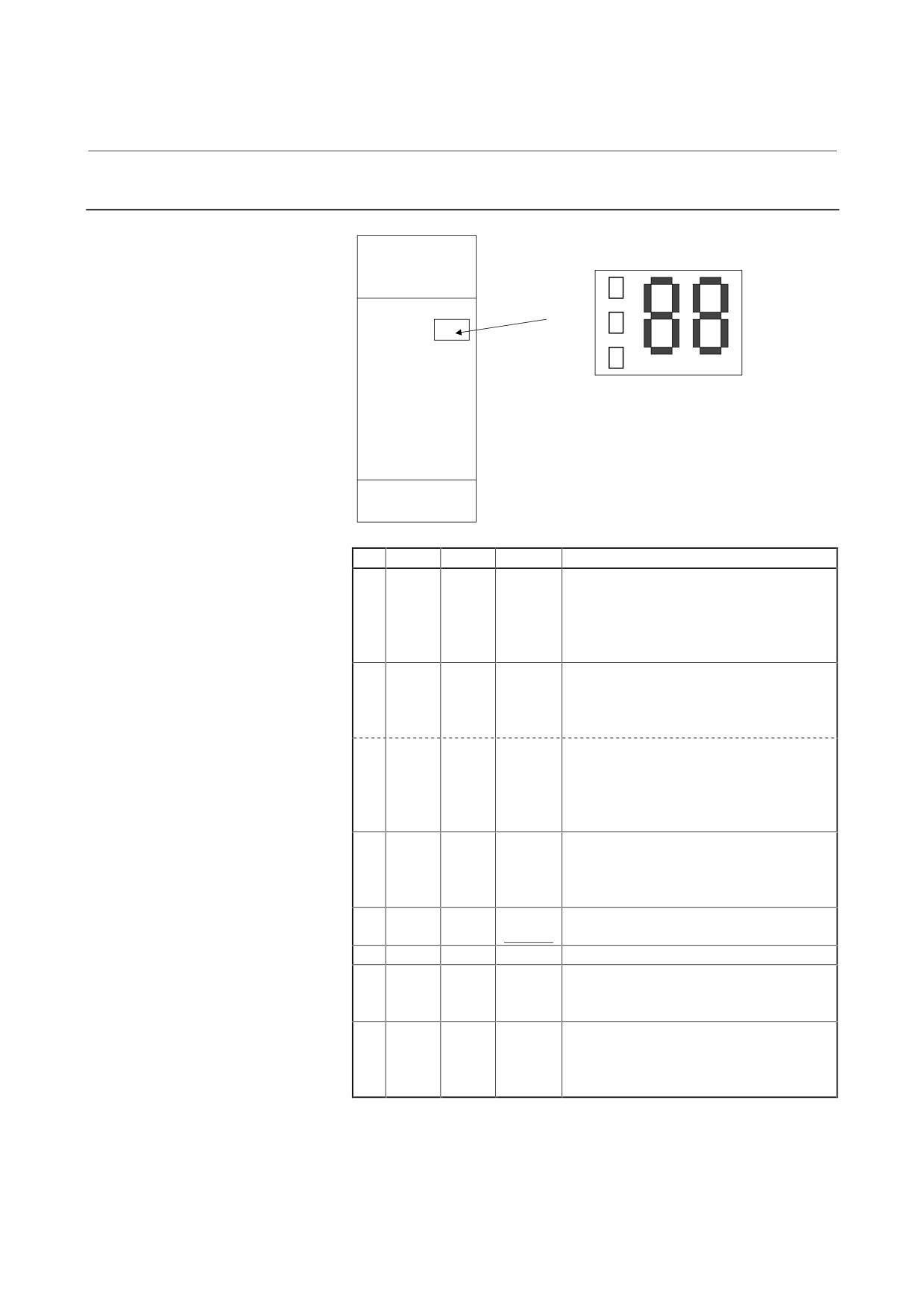
4.3.1
STATUS Display
STATUS
PIL
ALM
ERR
No.
ALM
ERR
STATUS
Description
1.
No
The PIL LED (power ON indicator) is off.
indication
The control power supply has not been
switched on.
The power supply circuit is defective. See
Section 3.1.2.
2.
20
For about 1.0 s after the control power
supply is switched on, the lower two digits of
the ROM series No. are indicated.
↓
Example) 20: ROM series No. 9D20
3.
04
The ROM edition number is displayed for
about 1.0 s. 01, 02, 03, and so on
correspond to A, B, C, and so on,
respectively.
Example) 04: ROM edition D
4.
--
The CNC has not been switched on.
Blinking
The machine is waiting for serial
communication and parameter loading to
end.
5.
--
Parameter loading has ended.
Lighting
The motor is not supplied with power.
6.
00
The motor is supplied with power.
7.
Lighting
01 or
Alarm state
above is
The SPM is not operable.
displayed.
See Section 3.4 of Part II.
8.
Lighting
01 or
Error state
above is
Incorrect parameter setting or improper
displayed.
sequence.
See Section 4.3.3 of Part II.
The PIL lamp is always on while the control power is being supplied.
- 50 -
4. CONFIRMATION OF
B-65165E/02
START-UP PROCEDURE
THE OPERATION
4.3.2
Troubleshooting at Startup
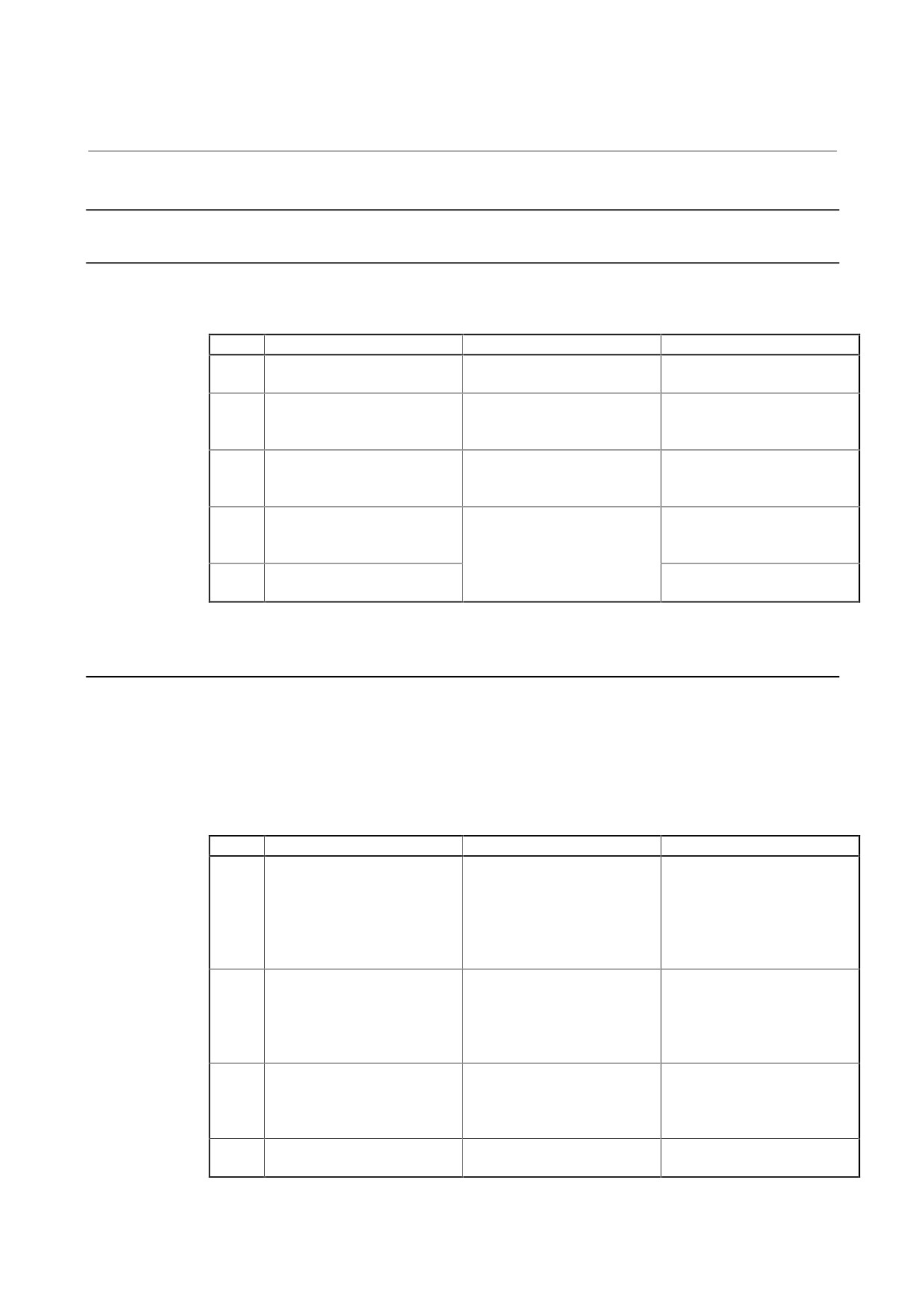
4.3.2.1 The PIL LED (power-on indicator) is off.
(1) When the PIL LED on the spindle amplifier module does not
come on after the main circuit breaker is turned on
No.
Cause of trouble
Check method
Action
1
The 200-V control power is not
The PSM PIL lamp is off.
Check the cable attached to
supplied.
CX1A of PSM.
2
The cable attached to
The PSM PIL lamp is on.
Check the cabling.
connector CX2A/B is
defective.
3
The power is externally
When all connectors except
Replace or repair the cable.
connected to 0 V, GND, or the
connector CX2A/B are
like.
detached, the PIL lamp is on.
4
There is a blown fuse on the
Even when all cables except
If the fuse blows, the printed
printed circuit board.
the cable attached to
circuit board may be faulty.
(A06B-6102-Hxxx, 6104-Hxxx)
connector CX2A/B are
Replace the SPM.
5
The printed circuit board is
detached, the PIL lamp does
Replace the SPM.
defective.
not come on.
4.3.2.2
The STATUS display is blinking with "--."
(1) When no spindle communication alarm message is indicated on
the CNC
Check whether the CNC software option setting or bit setting is
correct.
(2) When a communication alarm message is indicated on the CNC
No.
Cause of trouble
Check method
Action
1
The SPM switch setting is
When a second SPM is
Correct the switch setting.
incorrect.
connected, switch S1 is set to
For A06B-6072-Hxxx, A06B-
ON.
6078-H215 to H230, and
When no other SPM is
A06B-6078-H315 to H330 only
connected, switch S1 is set to
OFF.
2
The cable is incorrect.
Note that the cable used for
Replace the cable with a
connecting an electric/optical
correct cable.
adapter and the cable
connected directly to the CNC
differ in specifications.
3
The cable is defective.
Check whether the cable is
Repair or replace the cable.
broken.
Check for short-circuit in the
connector.
4
The printed circuit board is
Replace the SPM.
defective.
- 51 -

4. CONFIRMATION OF
THE OPERATION
START-UP PROCEDURE
B-65165E/02
4.3.2.3 The motor does not turn.
(1) When "--" is indicated on the STATUS display of the SPM
Check whether spindle control signals are input. (An example for
the first spindle is given below.)
FS0
FS15
FS16
#7
#6
#5
#4
#3
#2
#1
#0
G229
G227
G070
MRDYA
SFRA
SRVA
G230
G226
G071
*ESPA
(2) When "00" is indicated on the STATUS display of the SPM
No spindle speed command is input.
Refer to "FANUC AC SPINDLE MOTOR α series
Parameter Manual," and check related parameters.
(3) When an alarm number is indicated on the SPM
See the description of the alarm number in Section 3.4 of Part II.
4.3.2.4 A specified speed cannot be obtained.
(1) When the speed always differs from a specified speed
Check parameters.
Refer to "FANUC AC SPINDLE MOTOR α series
Parameter Manual," and check related parameters.
(2) When an alarm number is indicated on the SPM
See the description of the alarm number in Section 3.4 of Part II.
- 52 -
4. CONFIRMATION OF
B-65165E/02
START-UP PROCEDURE
THE OPERATION
4.3.2.5
When cutting is not performed, the spindle vibrates, making
noise.
(1)
The spindle vibrates only when the spindle speed has reached or is
at a particular speed level.
Check whether the spindle also vibrates when the motor is turning
by inertia. If noise is unchanged, investigate the source of
mechanical vibration. There are several methods to turn the
spindle by inertia as explained below. Because these methods
involve machine sequences, consult with the machine tool
builder.
A. Setting spindle control signal MPOF (FS16 for the first
spindle: G73#2, FS15 for the first spindle: G228#2) to 1
immediately causes the spindle to turn by inertia.
B. Set ALSP (FS16: bit 2 of parameter No. 4009, FS15 for the
first spindle: bit 2 of parameter No. 3009) to 1. Then, when
the power to the CNC is turned off during spindle rotation,
the spindle turns by inertia.
(On the spindle amplifier
module, alarm 24 is indicated.)
(2)
When noise is generated at the time the motor is stopped or at any
time
A. See Subsection 4.3.4 of this part, and check and adjust the
waveform of the spindle sensor.
B. Check that the motor part number matches its parameters.
For details, refer to "FANUC AC SPINDLE MOTOR α
series Parameter Manual."
C. Adjust the velocity loop gain and so forth.
For details, refer to "FANUC AC SPINDLE MOTOR α
series Parameter Manual."
4.3.2.6 An overshoot or hunting occurs.
Refer to "FANUC AC SPINDLE MOTOR α series Parameter
Manual," and adjust parameters.
- 53 -
4. CONFIRMATION OF
THE OPERATION
START-UP PROCEDURE
B-65165E/02
4.3.2.7 Cutting power weakens or acceleration/deceleration slows
down.
(1) When the load meter does not indicate the maximum output
A. A mechanical element such as a belt slip may occur.
(2) When the load meter indicates the maximum output
A. Check whether the torque limit signal is input incorrectly.
(An example for the first spindle is given below.)
FS0
FS15
FS16
#7
#6
#5
#4
#3
#2
#1
#0
G229
G227
G070
TLMHA
TLMLA
B. Check that the motor part number matches its parameters.
For details, refer to "FANUC AC SPINDLE MOTOR α
series Parameter Manual."
C. Check whether the output limit pattern is set incorrectly.
For details, refer to "FANUC AC SPINDLE MOTOR α
series Parameter Manual."
- 54 -
4. CONFIRMATION OF
B-65165E/02
START-UP PROCEDURE
THE OPERATION
4.3.3
Status Error Indication Function
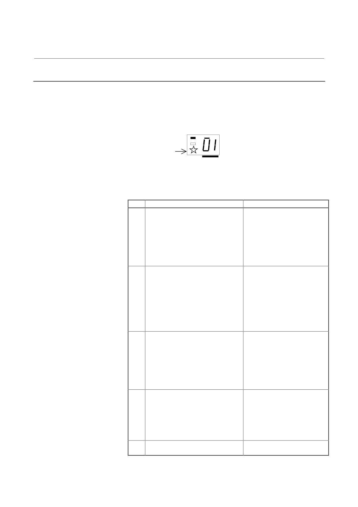
When there is a sequence or parameter error, the error LED (yellow) in
the display section of the spindle amplifier module (SPM) goes on with
an error code displayed. This can ease troubleshooting at the time of
machine startup.
status
The error LED
(yellow) lights.
An error code is indicated. (from 01)
When the spindle amplifier module does not operate for a certain
function, check whether the status error is indicated. The status error
number does not appear on the CNC screen.
No.
Description
Action
01
Although neither *ESP (emergency
Check the *ESP and MRDY
stop signal) (there are two types of
sequences. (For MRDY, pay
signals, a PMC signal and PSM contact
attention to the parameter that
signal) nor MRDY (machine ready
specifies whether to use the
signal) has been input, SFR (forward
MRDY signal (FS16i: bit 0 of
rotation signal), SRV (reverse rotation
parameter No. 4001).)
signal), or ORCM (orientation
command) is input.
02
When the spindle motor is equipped
Check the speed detector
with a high-resolution magnetic pulse
parameter of the spindle motor
coder (Cs sensor) (FS16i: bits 6 and 5
(FS16i: bits 2, 1, and 0 of
of parameter No.4001 = 0, 1), 128 λ/rev
parameter No. 4011).
must be set for the speed detector
(FS16i: bits 2, 1, and 0 of parameter
No. 4011 = 0, 0, 1). However, other
than 128 λ/rev is set. In this case, the
motor is not activated.
03
Although the use of a high-resolution
Check the parameters of the
magnetic pulse coder (FS16i: bit 5 of
detector for Cs contour control
parameter No. 4001 = 1) or the use of
(FS16i: bit 5 of parameter No.
the Cs contour control function by the α
4001 and bit 4 of parameter No.
sensor (FS16i: bit 4 of parameter No.
4018).
4018 = 1) is not specified, a Cs control
command is input. In this case, the
motor is not activated.
04
Although the parameter for using the
Check the parameter of the
position coder signal (FS16i: bit 2 of
position coder signal (FS16i: bit 2
parameter No. 4001 = 1) is not set, a
of parameter No. 4001).
command for servo mode (rigid tapping
or spindle positioning) or spindle
synchronization is input. In this case,
the motor is not activated.
05
Although no orientation option is set, an
Check the software option for
orientation command (ORCM) is input.
orientation.
(Continued)
- 55 -

4. CONFIRMATION OF
THE OPERATION
START-UP PROCEDURE
B-65165E/02
No.
Description
Action
06
Although no output switching option is
Check the software option for
set, low-speed winding is selected
spindle output switching and the
(RCH = 1).
power line status signal (RCH).
07
Although Cs contour control mode is
Check the sequence (CON, SFR,
specified, neither SFR nor SRV is input.
and SRV).
08
Although servo mode (rigid tapping or
Check the sequence (SFR and
spindle positioning) is specified, neither
SRV).
SFR nor SRV is input.
09
Although spindle synchronization mode
Check the sequence (SPSYC,
is specified, neither SFR nor SRV is
SFR, and SRV).
input.
10
In Cs contour control mode, another
Do not specify another operation
operation mode (servo mode, spindle
mode during execution of the Cs
synchronization, or orientation) is
contour control command. Before
specified.
entering another mode, cancel the
Cs contour control command.
11
In servo mode (rigid tapping or spindle
Do not specify another operation
positioning), another operation mode
mode during execution of the
(Cs contour control, spindle
servo mode command. Before
synchronization, or orientation) is
entering another mode, cancel
specified.
servo mode.
12
During spindle synchronization,
Do not specify another operation
another operation mode (Cs contour
mode during execution of the
control, servo mode, or orientation) is
spindle synchronization
specified.
command. Before entering
another mode, cancel the spindle
synchronization command.
13
When an orientation specification is
Do not specify another operation
specified, another operation mode (Cs
mode during execution of the
contour control, servo mode, or
orientation command. Before
synchronization control) is specified.
entering another mode, cancel the
orientation command.
14
The SFR signal and SRV signal are
Input one of the SFR and SRV
input at the same time.
signals.
15
Although the parameter to use the
Check the setting of the
differential mode function (FS16i: bit 5
parameter (FS16i: bit 5 of
of parameter No. 4000 = 1) is set, Cs
parameter No. 4000) and the PMC
axis contour control is specified.
signal (CON).
16
Although the parameter not to use the
Check the setting of the
differential mode function (FS16i: bit 5
parameter (FS16i: bit 5 of
of parameter No. 4000 = 0) is set, a
parameter No. 4000) and the PMC
differential speed mode command
signal (DEFMD).
(DEFMD) is input.
17
The parameter settings for the speed
Check the parameter settings
detector (FS16i: bits 2, 1, and 0 of
(FS16i: bits 2, 1, and 0 of
parameter No. 4011) are invalid.
parameter No. 4011).
(There is no speed detector that
matches the settings.)
- 56 -

4. CONFIRMATION OF
B-65165E/02
START-UP PROCEDURE
THE OPERATION
(Continued)
No.
Description
Action
18
Although the parameter not to use the
Check the parameter setting
position coder signal (FS16i: bit 2 of
(FS16i: bit 2 of parameter No.
parameter No. 4001 = 0) is set, a
4001) and the PMC signal
position coder orientation command
(ORCM).
(ORCMA) is input.
19
During magnetic sensor orientation,
Do not specify another operation
another operation mode is specified.
mode during execution of the
orientation command. Before
entering another mode, cancel the
orientation command.
20
When the use of the slave operation
Check the parameter settings
mode function (FS16i: bit 5 of
(FS16i: bit 5 of parameter No.
parameter No. 4014 = 1) is set, the use
4001, bit 5 of parameter No. 4014,
of a high-resolution magnetic pulse
and bit 4 of parameter No. 4018).
coder (FS16i: bit 5 of parameter No.
4001 = 1) or the use of the Cs contour
control function by the α sensor (FS16i:
bit 4 of parameter No. 4018 = 1) is set.
These settings cannot be made at the
same time.
21
During position control (such as servo
Input the slave operation mode
mode and orientation), a slave
command (SLV) in normal
operation mode command (SLV) is
operation mode.
input.
22
In slave operation mode (SLVS = 1), a
Input the position control
position control command (such as
command in normal operation
servo mode and orientation) is input.
mode.
23
Although the parameter not to use the
Check the parameter setting
slave operation mode function (FS16i:
(FS16i: bit 5 of parameter No.
bit 5 of parameter No. 4014 = 0) is set,
4014) and the PMC signal (SLV).
the slave operation mode command
(SLV) is input.
24
After orientation is performed in
Check the PMC signal (INCMD).
incremental mode (INCMD = 1) first, an
Perform an absolute position
absolute position command (INCMD =
command orientation first.
0) is input next.
25
Although the spindle amplifier is not
Check the spindle amplifier
SPM type 4, the use of the Cs contour
specification and parameter
control function by the α sensor (FS16i:
setting (FS16i: bit 4 of parameter
bit 4 of parameter No. 4018 = 1) is set.
No. 4018).
- 57 -
4. CONFIRMATION OF
THE OPERATION
START-UP PROCEDURE
B-65165E/02
4.3.4
Checking The Feedback Signal Waveform
First, refer to Subsection 9.2.3 of "FANUC SERVO AMPLIFIER α
series Descriptions"
(B-65162E), and make sure that the spindle
sensors and other detectors are connected at the correct points. Next,
see the table given below to find the corresponding check terminal
names on the check board from the sensor connector connection points.
Do not observe feedback signals before the parameters for the detectors
that are set. Phase A, B, and Z signals may not be output correctly until
the parameters are loaded from the CNC.
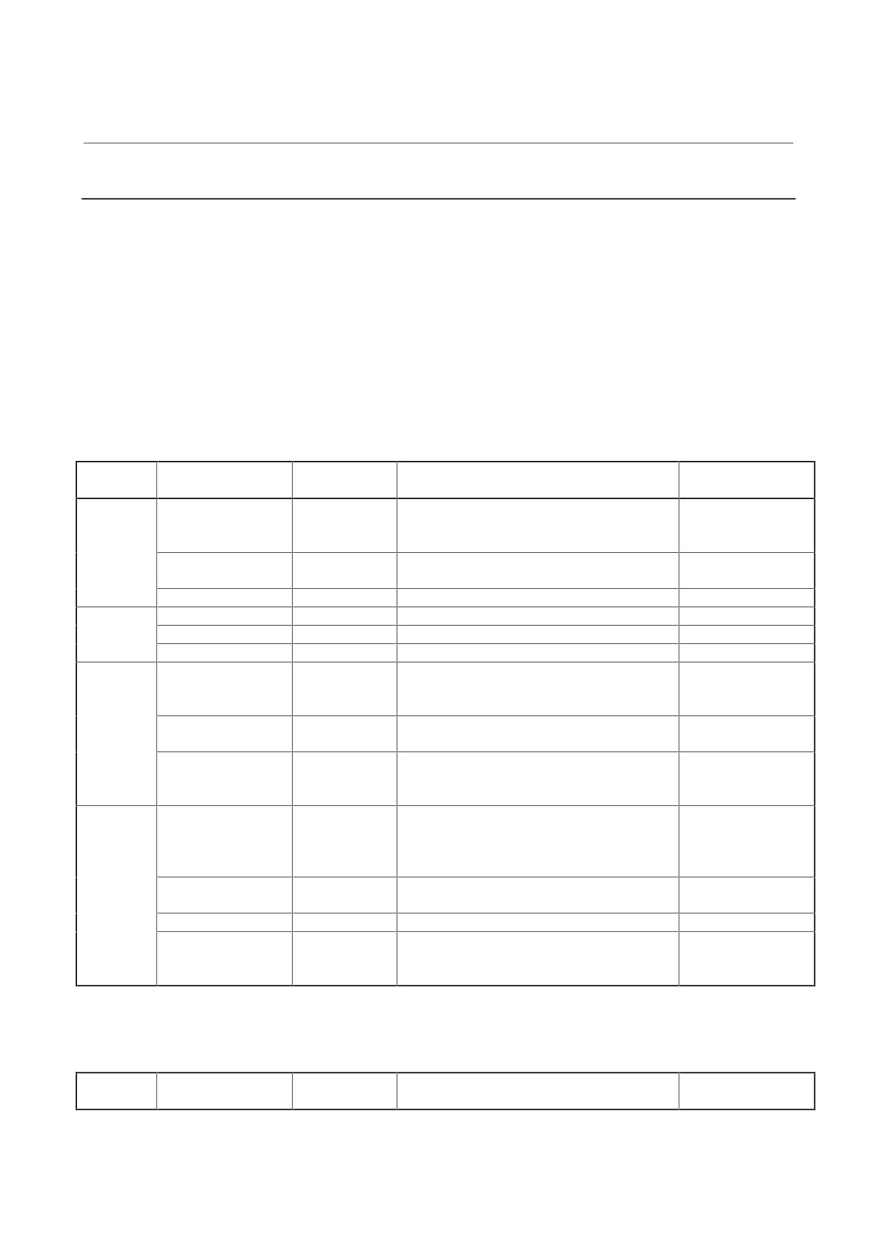
Signals input to the SPM and corresponding check terminals on the
check board
(1) SPM type 1, type 2, and type 4
SPM input
Connector pin
Check
Main sensors
Remarks
connector
signal
terminal name
JY2
Phase A: pin 5, 6
PA1
M, MZ, and BZ sensors
Phase B: pin 7, 8
PB1
Low resolution side of the high-resolution
magnetic pulse coder (128 to 384 λ)
Phase A: pin 3, 4
PA4
High resolution side of the high-resolution
For type 2 only
Phase B: pin 17, 19
PB4
magnetic pulse coder (1000 to 3000 λ)
Phase Z: pin 1, 2
PS1
MZ and BZ sensors (one-rotation signal)
JY3
pin 18
EXTSC1
Proximity switch (external one-rotation signal)
pin 1, 3
LSA1
Magnetic sensor (LSA signal)
pin 5, 14
MSA1
Magnetic sensor (MSA signal)
*1
JY4
Phase A: pin 5, 6
PAD
α position coder (1024 p)
Parameter setting
Phase B: pin 7, 8
PBD
Low resolution side of the high-resolution
position coder (1024 p)
Phase A: pin 3, 4
PA3
High resolution side of the high-resolution
For type 2 only
Phase B: pin 17, 19
PB3
position coder (3000 λ)
Phase Z: pin 1, 2
PSD
α position coder (one-rotation signal)
Parameter setting
High-resolution position coder (one-rotation
signal)
JY5
Phase A: pin 5, 6
PA2
M, MZ, and BZ sensors
For types 2 and 4
Phase B: pin 7, 8
PB2
Low resolution side of a high-resolution
only
magnetic pulse coder (128 to 384 λ)
α position coder S (1024 λ)
Phase A: pin 3, 4
PA3
High resolution side of a high-resolution
For type 2 only
Phase B: pin 17, 19
PB3
magnetic pulse coder (1000 to 3000 λ)
Phase Z: pin 1, 2
PS2
MZ and BZ sensors (one-rotation signal)
For type 4 only
Phase Z: pin 1, 2
PSD
α position coder S (one-rotation signal)
Parameter setting
High-resolution magnetic pulse coder (one-
rotation signal)
*1
This check terminal is provided for A20B-1005-0740 only. With
A20B-2001-0830, MSA is observed on CH1 or CH2.
Only for SMPs of which the specification is A06B-6078-H315 to 330
JY6
Phase A: pin 5, 6
PA2
M, MZ, and BZ sensors
For type 2 only
Phase B: pin 7, 8
PB2
- 58 -

4. CONFIRMATION OF
B-65165E/02
START-UP PROCEDURE
THE OPERATION
(2) SPM type 3
SPM input
Connector pin
Check
Main sensors
Remarks
connector
signal
terminal name
JY2
Phase A: pin 5, 6
PA1
M, MZ, and BZ sensors
Main side
Phase B: pin 7, 8
PB1
Phase Z: pin 1, 2
PS1
MZ and BZ sensors (one-rotation signal)
Main side
JY6
Phase A: pin 5, 6
PA2
M, MZ, and BZ sensors
Sub side
Phase B: pin 7, 8
PB2
Phase Z: pin 1, 2
PS2
MZ and BZ sensors (one-rotation signal)
Sub side
JY4 or
Phase A: pin 5, 6
PAD
α position coder (1024 p)
When the main side
JY8
Phase B: pin 7, 8
PBD
is selected by
and
spindle switching
Phase A: pin 5, 6
control, signals are
Phase B: pin 7, 8
output on JY4.
When the sub side
is selected, signals
are output on JY8.
Parameters must be
set correctly.
Phase Z: pin 1, 2
PSD
α position coder (one-rotation signal)
When the main side
and
is selected by
Phase Z: pin 1, 2
spindle switching
control, signals are
output on JY4.
When the sub side
is selected, signals
are output on JY8.
Parameters must be
set correctly.
JY3
pin 18
EXTSC1
Proximity switch (external one-rotation signal)
Main side
pin 1, 3
LSA1
Magnetic sensor (LSA signal)
Main side
pin 5, 14
MSA1
Magnetic sensor (MSA signal)
Main side(*1)
For A20B-1005-
0740 only
JY7
pin 18
EXTSC2
Proximity switch (external one-rotation signal)
Sub side
pin 1, 3
LSA2
Magnetic sensor (LSA signal)
Sub side
pin 5, 14
MSA2
Magnetic sensor (MSA signal)
Sub side(*1)
For A20B-1005-
0740 only
*1
With A20B-2001-0830, MSA is observed on CH1 or CH2.
- 59 -
4. CONFIRMATION OF
THE OPERATION
START-UP PROCEDURE
B-65165E/02
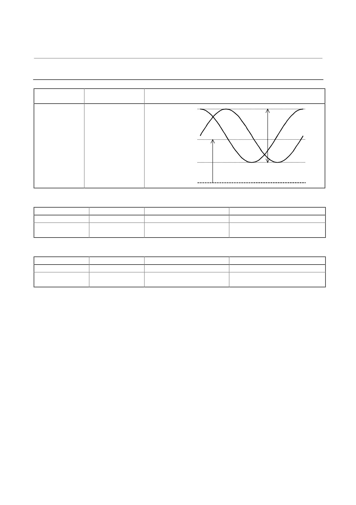
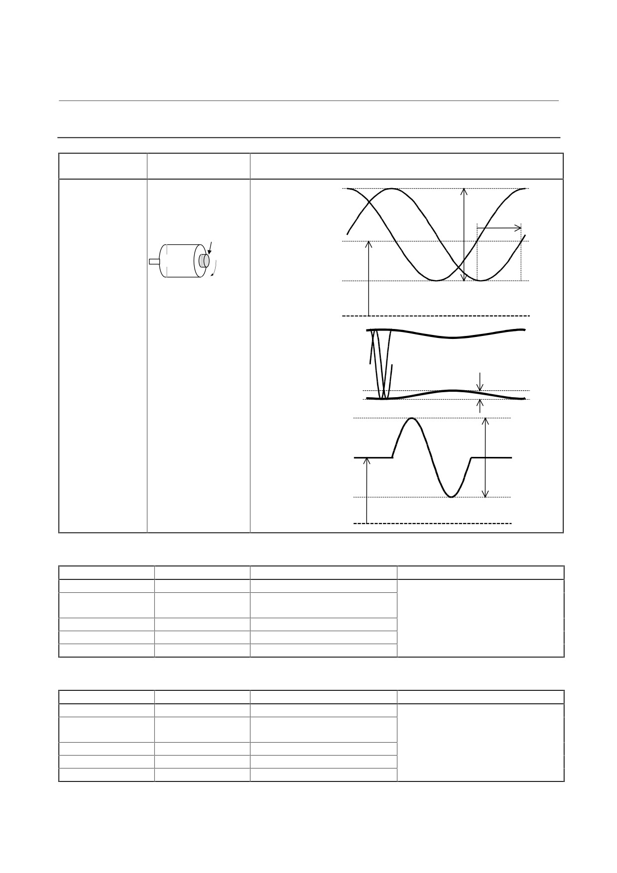
4.3.4.1 M sensor
Measurement
Measurement
Sample waveform
location
condition
Input on JY2 side
The speed must be
Waveforms of phase
PA1, PB1
1500 min-1 or less.
Vpp
A and phase B
PA1 (PA2)
For sub side
selected by spindle
switching:
Voffs
Input on JY6 side
PB1 (PB2)
PA2, PB2
0 V
For the SPM type 4 or SPM of which the specification is A06B-6102-Hxxx#H520 or A06B-6104-Hxxx#H520
Measurement item
Specification
Measurement method
Adjustment method
Vpp
0.36 to 0.50 Vp-p
Adjustment is normally unnecessary.
Voffs
2.5 V ±100 mV
Use the DC range of a digital
Level check is possible, but
voltmeter.
adjustment is not possible.
For SPMs other than the above
Measurement item
Specification
Measurement method
Adjustment method
Vpp
0.64 to 0.90 Vp-p
Adjustment is normally unnecessary.
Voffs
2.5 V ±90 mV
Use the DC range of a digital
Level check is possible, but
voltmeter.
adjustment is not possible.
- 60 -
4. CONFIRMATION OF
B-65165E/02
START-UP PROCEDURE
THE OPERATION
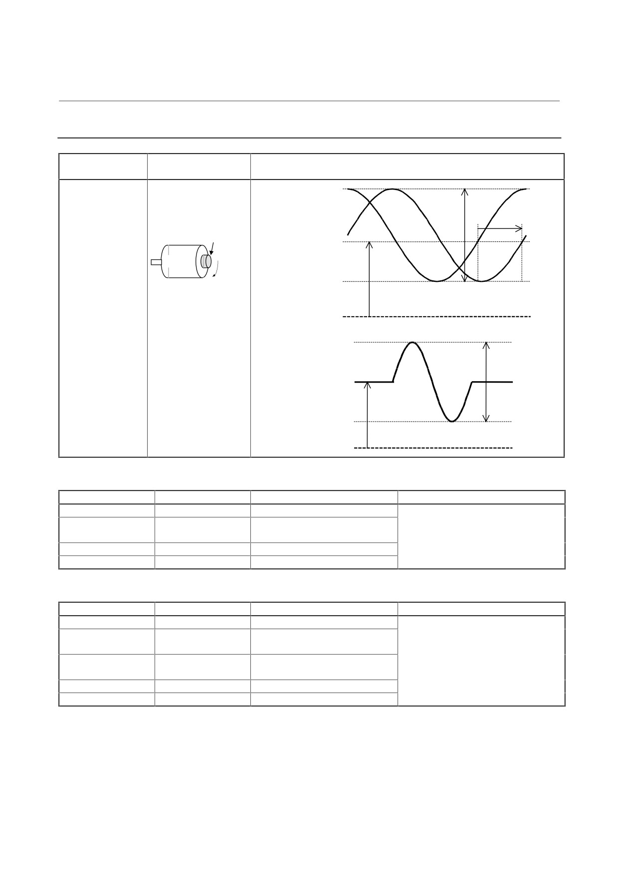
4.3.4.2 MZ and BZ sensors
Measurement
Measurement
Sample waveform
location
condition
Input on JY2 side
The speed must be
Waveforms of phase
PA1, PB1
1500 min-1 or less.
Vpp
A and phase B
PA1 (PA2)
For SPM type 4:
Rotation direction: CW
Input on JY5 side
Detection gear
Vphase
PA2, PB2
Voffs
PB1 (PB2)
Motor
For sub side
CW
selected by spindle
switching:
0 V
Input on JY6 side
PA2, PB2
Ripples of phase A and
phase B
PA1, PB1 (PA2, PB2)
Vrip
Waveform of
phase Z
(Z - *Z)
Vpz
Voffz
0 V
For the SPM type 4 or SPM of which the specification is A06B-6102-Hxxx#H520 or A06B-6104-Hxxx#H520
Measurement item
Specification
Measurement method
Adjustment method
Vpp
0.5 to 1.2 Vp-p
Normally, the MZ sensor need not be
Voffs, Voffz
2.5 V ±100 mV
Use the DC range of a digital
adjusted. For Voffs and Voffz, only
voltmeter.
level check is possible, but
Vphase
90 ±3°
adjustment is not possible.
Vrip
< 70 mV
Vpz
> 1.0 V
For SPMs other than the above
Measurement item
Specification
Measurement method
Adjustment method
Vpp
0.66 to 0.93 Vp-p
Normally, the MZ sensor need not be
Voffs, Voffz
2.5 V ±272 mV
Use the DC range of a digital
adjusted. For Voffs and Voffz, only
voltmeter.
level check is possible, but
Vphase
90 ±3°
adjustment is not possible.
Vrip
< 70 mV
Vpz
> 1.0 V
- 61 -
4. CONFIRMATION OF
THE OPERATION
START-UP PROCEDURE
B-65165E/02
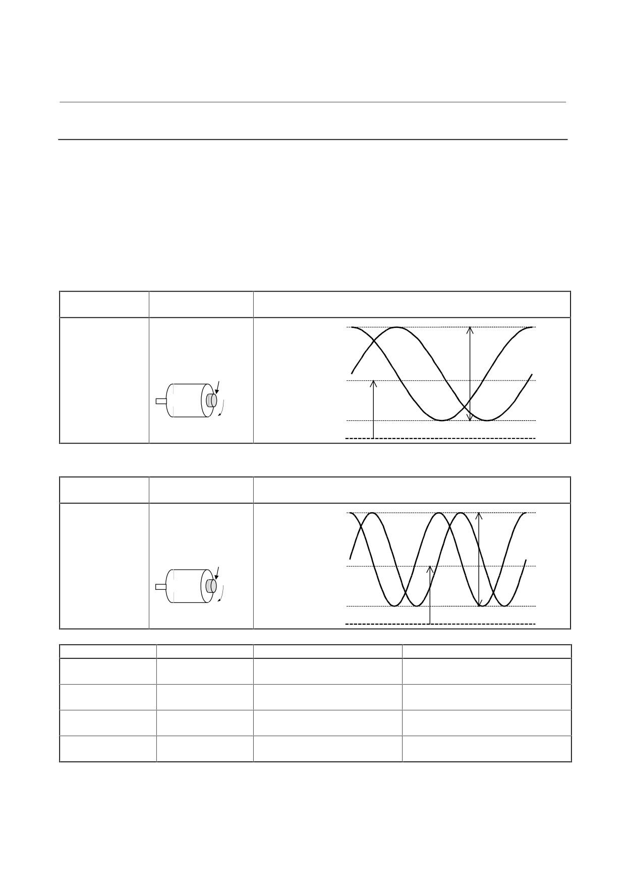
4.3.4.3 MZ sensor for α 0.5 (A06B-0866-B390) (old specification)
Measurement
Measurement
Sample waveform
location
condition
Input on JY2 side
The speed must be
Waveforms of phase
PA1, PB1
1500 min-1 or less.
Vpp
A and phase B
PA1 (PA2)
For sub side
Rotation direction: CW
selected by spindle
Detection gear
Vphase
switching:
Voffs
Input on JY6 side
PB1 (PB2)
Motor
PA2, PB2
CW
0 V
Waveform of
phase Z
(Z - *Z)
Vpz
Voffz
0 V
For the SPM type 4 or SPM of which the specification is A06B-6102-Hxxx#H520 or A06B-6104-Hxxx#H520
Measurement item
Specification
Measurement method
Adjustment method
Vpp
0.5 to 1.2 Vp-p
Normally, the MZ sensor need not be
Voffs,Voffz
2.5 V ±100 mV
Use the DC range of a digital
adjusted. For Voffs and Voffz, only
voltmeter.
level check is possible, but
Vphase
90 ±3°
adjustment is not possible.
Vpz
> 1.0 V
For SPMs other than the above
Measurement item
Specification
Measurement method
Adjustment method
Vpp
0.50 to 1.45 Vp-p
Normally, the MZ sensor need not be
Voffs
2.5 V ±295 mV
Use the DC range of a digital
adjusted. For Voffs and Voffz, only
voltmeter.
level check is possible, but
Voffz
2.5 V ±500 mV
Use the DC range of a digital
adjustment is not possible.
voltmeter.
Vphase
90 ±3°
Vpz
> 2.0 V
- 62 -
4. CONFIRMATION OF
B-65165E/02
START-UP PROCEDURE
THE OPERATION
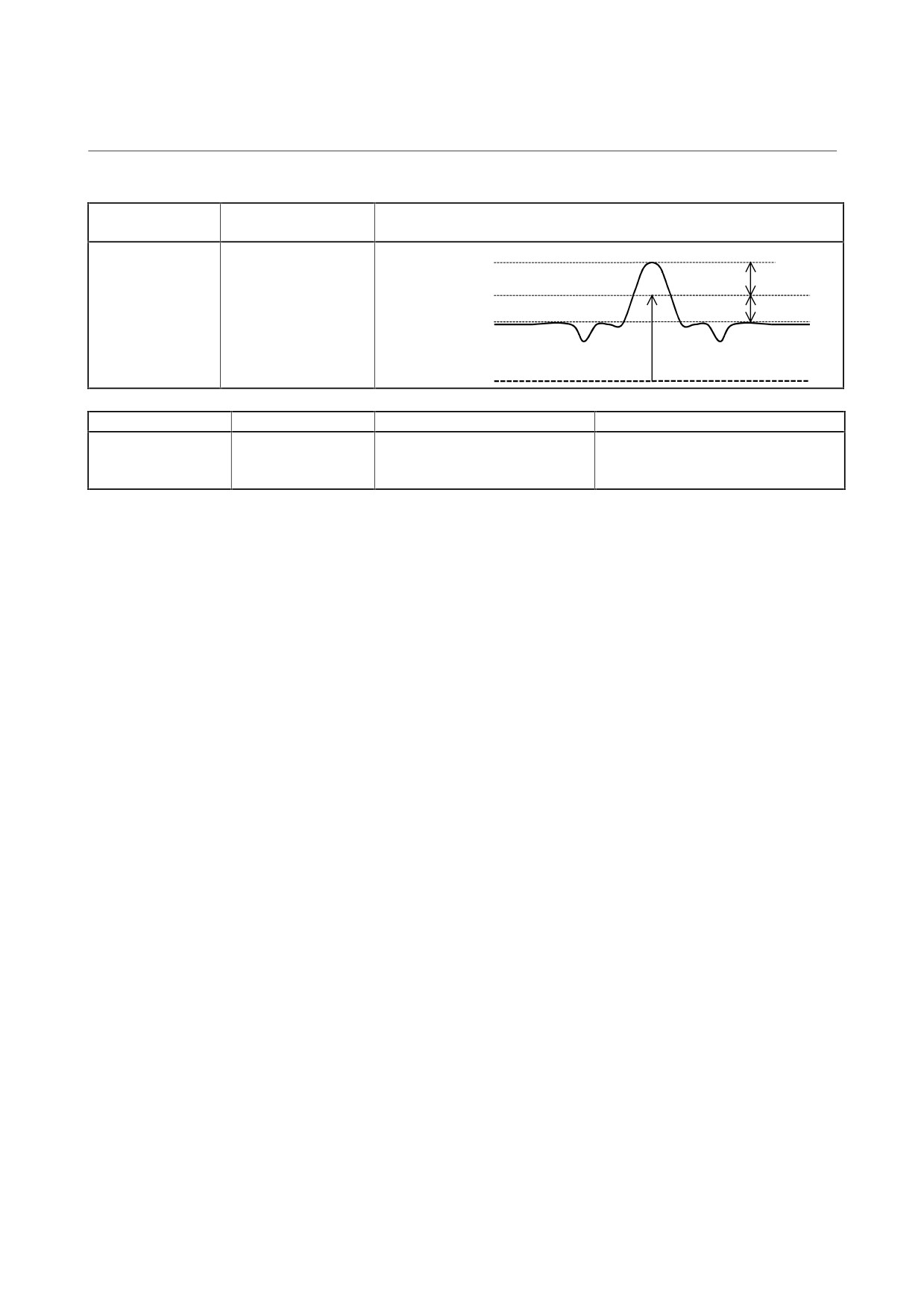
4.3.4.4 High-resolution magnetic pulse coder
After mounting a high-resolution magnetic pulse coder on the machine,
check waveforms. If a measurement value exceeds the specified range,
adjustment is required.
After mounting the sensor, you should check waveforms before
installing components such as a pulley, drawbar, and brake to make
adjustment easier.
(1) Adjusting check pins on the preamplifier
Signal on the low-resolution side 128 to 384 λ
Measurement
Measurement
Sample waveform
location
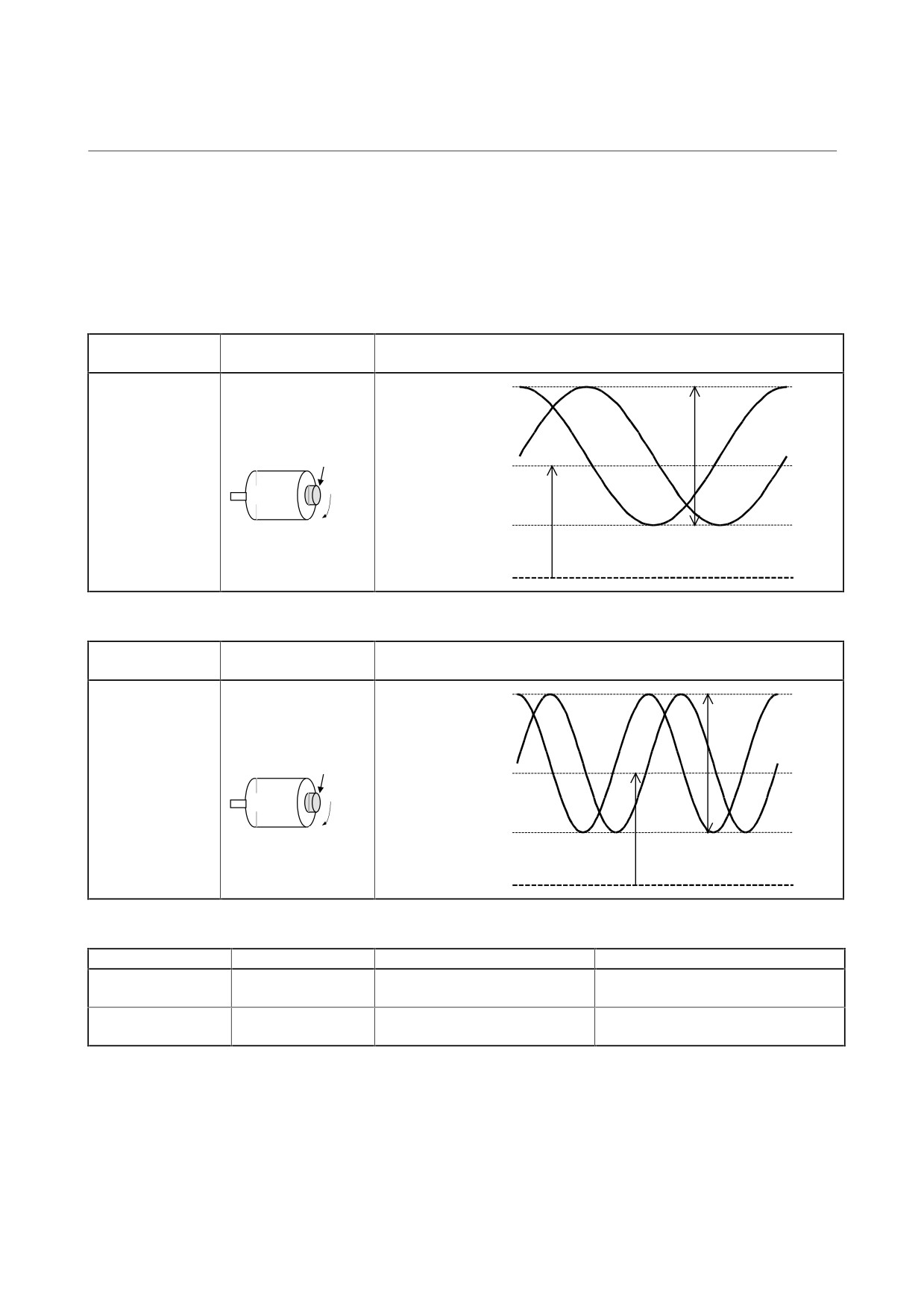
condition
Check pins A3 and
The speed must be 500
Waveforms of phase
B3 on the
min-1 or less.
Vpp
A and phase B
A3
preamplifier
Rotation direction: CW
Detection gear
Voffs
B3
Motor
CW
0 V
Signal on the high-resolution side 1000 to 3000 λ
Measurement
Measurement
Sample waveform
location
condition
Check pins A1 and
The speed must be 500
Waveforms of phase
B1 on the
min-1 or less.
Vpp2
A and phase B
preamplifier
Rotation direction: CW
Detection gear
A1
Voffs2
B1
Motor
CW
0 V
Measurement item
Specification
Measurement method
Adjustment method
Vpp
0.36 to 0.50 Vp-p
Adjust potentiometers A3G and B3G
on the preamplifier.
Vpp2
0.80 to 1.0 Vp-p
Adjust potentiometers A1G and B1G
on the preamplifier.
Voffs
2.5 V ±50 mV
Use the DC range of a digital
Adjust potentiometers A3O and B3O
voltmeter.
on the preamplifier.
Voffs2
2.5 V ±10 mV
Use the DC range of a digital
Adjust potentiometers A1O and B1O
voltmeter.
on the preamplifier.
- 63 -
4. CONFIRMATION OF
THE OPERATION
START-UP PROCEDURE
B-65165E/02
One-rotation signal
Measurement
Measurement
Sample waveform
location
condition
Check pin Z on the
The speed must be 500
preamplifier
min-1 or less.
Waveform of
phase Z
Z2
2.5 V (VRM)
Z
Z1
0 V
Measurement item
Specification
Measurement method
Adjustment method
Z1, Z2
Z1 > 60 mV
Adjust potentiometer ZO on the
Z2 > 60 mV
preamplifier so that the value of Z1
and that of Z2 are almost the same.
- 64 -
4. CONFIRMATION OF
B-65165E/02
START-UP PROCEDURE
THE OPERATION
(2) Adjusting check pins on the check board
For the high-resolution magnetic pulse coder built into the motor,
waveforms are factory-adjusted. If a waveform exceeds a
specified value, however, adjust potentiometers on the
preamplifier.
Signal on the low-resolution side 128 to 384 λ
Measurement
Measurement
Sample waveform
location
condition
Input on JY2 side
The speed must be 500
Waveforms of phase
PA1, PB1
min-1 or less.
Vpp
A and phase B
PA2 (PA1)
Input on JY5 side
Rotation direction: CW
PA2, PB2
Detection gear
Voffs
PB2 (PB1)
Motor
CW
0 V
Signal on the high-resolution side 1000 to 3000 λ
Measurement
Measurement
Sample waveform
location
condition
Input on JY2 side
The speed must be 500
Waveforms of phase
PA4, PB4
min-1 or less.
Vpp2
A and phase B
Input on JY5 side
Rotation direction: CW
PA3, PB3
Detection gear
PA3 (PA4)
Voffs2
PB3 (PB4)
Motor
CW
0 V
For the SPM type 4 or SPM of which the specification is A06B-6102-Hxxx#H520 or 6104-Hxxx#H520
Measurement item
Specification
Measurement method
Adjustment method
Vpp
0.36 to 0.50 Vp-p
Adjust potentiometers A3G and B3G
on the preamplifier.
Vpp2
0.80 to 1.0 Vp-p
Adjust potentiometers A1G and B1G
on the preamplifier.
- 65 -