FANUC Alpha Series Motors and Modular Drives. Maintenance Manual (GFZ-65165E/02) - page 2
B-65165E/02
START-UP PROCEDURE
2. CONFIGURATIONS
2.1
CONFIGURATIONS
The FANUC servo amplifier α series consists of the units and
components listed below:
(1) Power supply module (PSM)
(basic)
(2) Servo amplifier module (SVM)
(basic)
(3) Spindle amplifier module (SPM)
(basic)
(4) AC reactor
(basic)
(5) Connectors (for connecting cables)
(basic)
(6) Fuses
(basic)
(7) Power transformer
(option)
(8) Fan adaptor
(option)
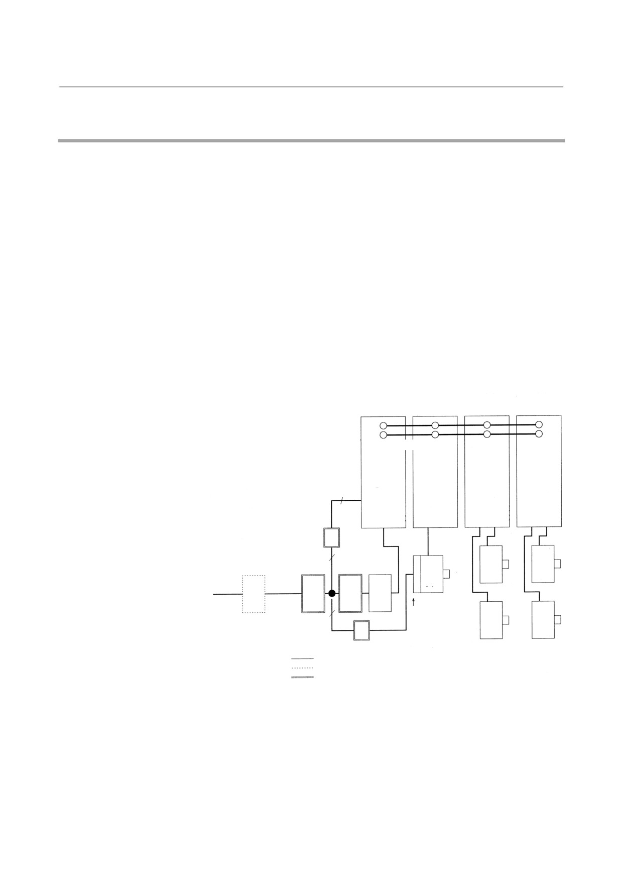
The diagram below shows an example of a basic configuration of the
FANUC servo amplifier α series system. The basic configuration
consists of two two-axis servo amplifier modules and one spindle
amplifier module.
Power supply
Spindle amplifier Servo amplifier
Servo amplifier
module
module
module (2-axis) module (2-axis)
P
N
DC link (300 VDC)
PSM
SPM
SVM
SVM
AC input for
control power
supply
200R,
200S, PE
1
UL VL WL PE
UL VL WL PE
L1 L2 L3 PE U V W PE
UM VM WM PE UM VM WM
Circuit breaker 2
Servo
Servo
Magnetic AC
Spindle
motor
motor
(380VAC)
200 VAC
1
contactor
reactor
motor
(415VAC)
220 VAC
Circuit
(460VAC)
230 VAC
breaker
1
3
Fan
Servo
Servo
Power transformer
3
motor
motor
Circuit breaker 3
: Standard
: Optional
: Units prepared by the machine tool builder
- 5 -
2. CONFIGURATIONS
START-UP PROCEDURE
B-65165E/02
NOTE
1
Refer to the Servo Amplifier α series Descriptions
(B-65162E) for combinations of the power supply
module, servo amplifier module, and spindle
amplifier module.
2
Always use the circuit breakers, magnetic contactor,
and AC reactor.
3
Install a surge suppressor between the power lines
and between each power line and a ground at the
input of the power magnetics cabinet to protect the
system from lightning surge.
- 6 -
B-65165E/02
START-UP PROCEDURE
2. CONFIGURATIONS
2.2
MAJOR COMPONENTS
2.2.1
Power Supply Modules
2.2.1.1 α series power supply modules
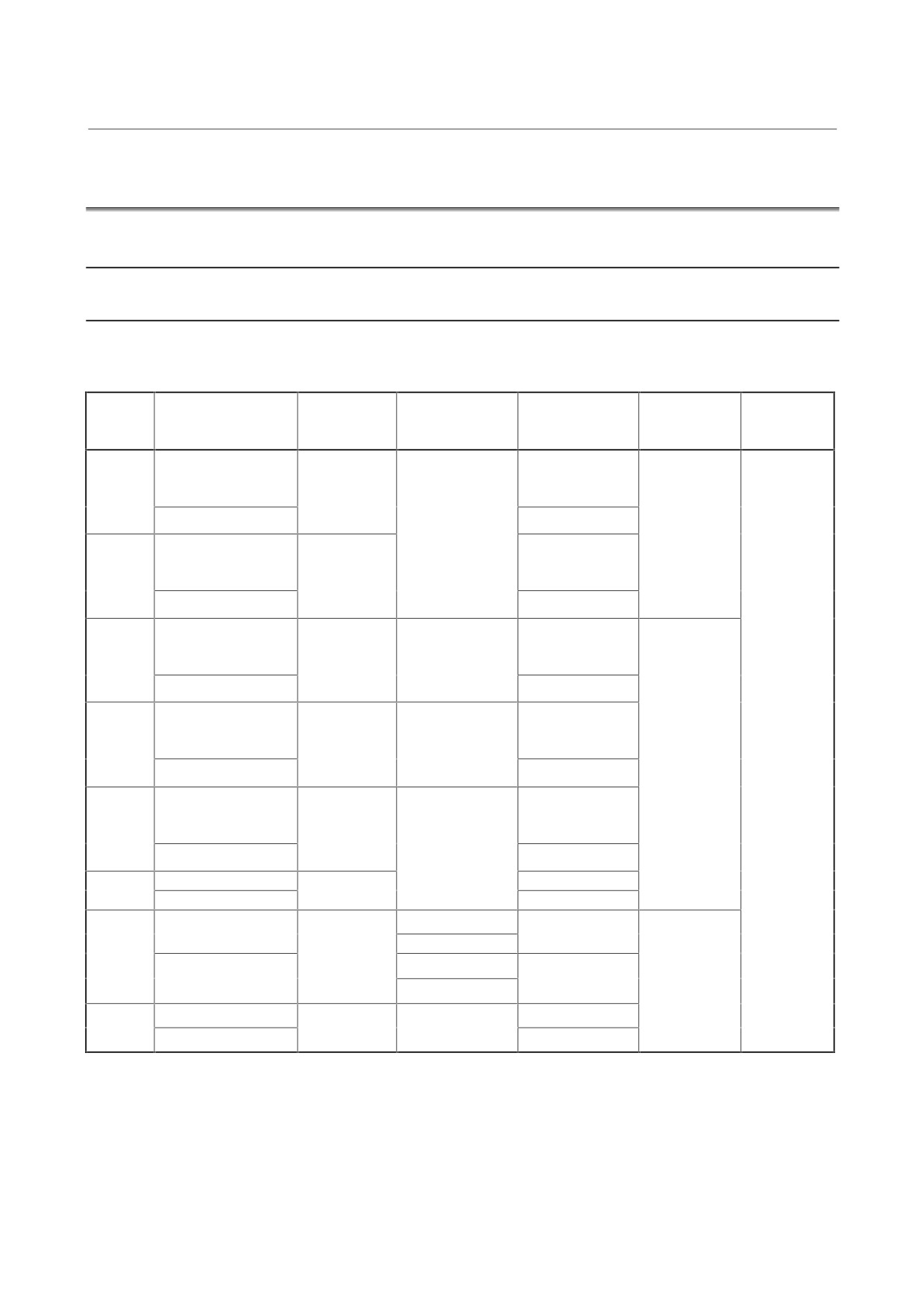
(1) Power supply modules (PSM) (200 VAC input, power regeneration
type), CE-marked products
Printed circuit
Connector
Unit
Wiring board
Driver board
Model
Order specification
board
board
specification
specification
specification
specification
specification
A06B-6077-
A16B-2202-0420
A06B-6077-H106
C106
(Revision 05D or
PSM-5.5
(Revision B or later)
(Revision B or
later)
A06B-6077-H106#BM
later)
A16B-2202-0423
A16B-2202-0661
A16B-2202-0420
A06B-6077-
A06B-6077-H111
(Revision 05D or
C111
(Revision B or later)
PSM-11
later)
(Revision B or
A06B-6077-H111#BM
later)
A16B-2202-0423
A16B-2202-0421
A20B-2902-
A06B-6087-
A06B-6087-H115
(Revision 05D or
0390
C115
(Revision B or later)
PSM-15
A20B-1006-0470
later)
(Revision B or
A06B-6087-H115#BM
later)
A16B-2202-0424
A16B-2202-0421
A06B-6087-
A06B-6087-H126
(Revision 05D or
C126
(Revision B or later)
PSM-26
A20B-1006-0471
later)
(Revision B or
A06B-6087-H126#BM
later)
A16B-2202-0424
A16B-2202-0421
A06B-6087-
A06B-6087-H130
(Revision 05D or
C130
(Revision B or later)
PSM-30
later)
(Revision B or
A20B-1006-0472
A06B-6087-H130#BM
later)
A16B-2202-0424
A06B-6087-H137
A06B-6087-
A16B-2202-0421
PSM-37
A06B-6087-H137#BM
C137
A16B-2202-0424
A20B-1006-0680
A20B-2002-
A06B-6087-H145
A16B-2202-0421
0080
A06B-6087-
A20B-1007-0650
PSM-45
C145
A20B-1006-0680
A06B-6087-H145#BM
A16B-2202-0424
A20B-1007-0650
A06B-6087-H155
A06B-6087-
A16B-2202-0421
PSM-55
A20B-1007-0650
A06B-6087-H155#BM
C155
A16B-2202-0424
* The PSM-45 has been replaced by the PSM-55 (as of August 1999).
- 7 -
2. CONFIGURATIONS
START-UP PROCEDURE
B-65165E/02
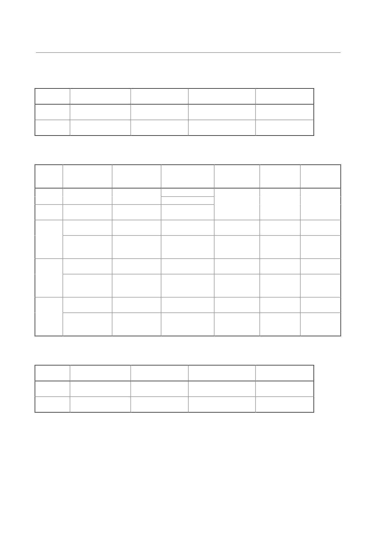
(2) Power supply modules
(PSMR) (200 VAC input, resistance
discharge type), CE-marked products
Wiring board
Printed circuit board
Model
Order specification
Unit specification
specification
specification
A06B-6081-H103
A16B-2202-0542
PSMR-3
A06B-6081-C103
A16B-2001-0890
(Revision C or later)
(Revision 06B or later)
A06B-6081-H106
A16B-2202-0541
PSMR-5.5
A06B-6081-C106
A16B-2001-0890
(Revision C or later)
(Revision 06B or later)
(3) Power supply modules
(PSM)
(200 VAC
input, power
regeneration type), CE-marked products
Printed circuit
Connector
Order
Unit
Wiring board
Driver board
Model
board
board
specification
specification
specification
specification
specification
specification
A06B-6077-H106
A06B-6077-C106
A16B-2202-0460
PSM-5.5
A16B-2202-0420
(Revision A)
(Revision A)
A16B-2202-0461
(Revision 04C or
A06B-6077-H111
A06B-6077-C111
PSM-11
A16B-2202-0461
earlier)
(Revision A)
(Revision A)
A20B-2001-
A20B-2001-
A06B-6077-H115
A06B-6071-C112
A20B-1005-0591
A16B-2202-0080
0011
0130
PSM-15
A16B-2202-0421
A20B-2902-
A06B-6087-H115
A06B-6087-C115
A20B-1006-0160
(Revision 04C or
0280
(Revision A)
(Revision A)
earlier)
A20B-2001-
A20B-2001-
A06B-6077-H126
A06B-6071-C122
A20B-1005-0590
A16B-2202-0080
0011
0130
PSM-26
A06B-6087-H126
A06B-6087-C126
A16B-2202-0421
A20B-2902-
(Revision B or
(Revision B or
A20B-1006-0161
(Revision 04C or
0280
earlier)
earlier)
earlier)
A20B-2001-
A20B-2001-
A06B-6077-H130
A06B-6071-C126
A20B-1005-0592
A16B-2202-0080
0011
0130
PSM-30
A06B-6087-H130
A06B-6087-C130
A16B-2202-0421
A20B-2902-
(Revision B or
(Revision B or
A20B-1006-0162
(Revision 04C or
0280
earlier)
earlier)
earlier)
(4) Power supply modules
(PSMR) (200 VAC input, resistance
discharge type), CE-marked products
Wiring board
Printed circuit board
Model
Order specification
Unit specification
specification
specification
A06B-6081-H103
A06B-6081-C103
A16B-2202-0542
PSMR-3
A16B-2300-0100
(Revision B or earlier)
(Revision B or earlier)
(Revision 05A or earlier)
A06B-6081-H106
A06B-6081-C106
A16B-2202-0541
PSMR-5.5
A16B-2300-0100
(Revision B or earlier)
(Revision B or earlier)
(Revision 05A or earlier)
- 8 -
B-65165E/02
START-UP PROCEDURE
2. CONFIGURATIONS
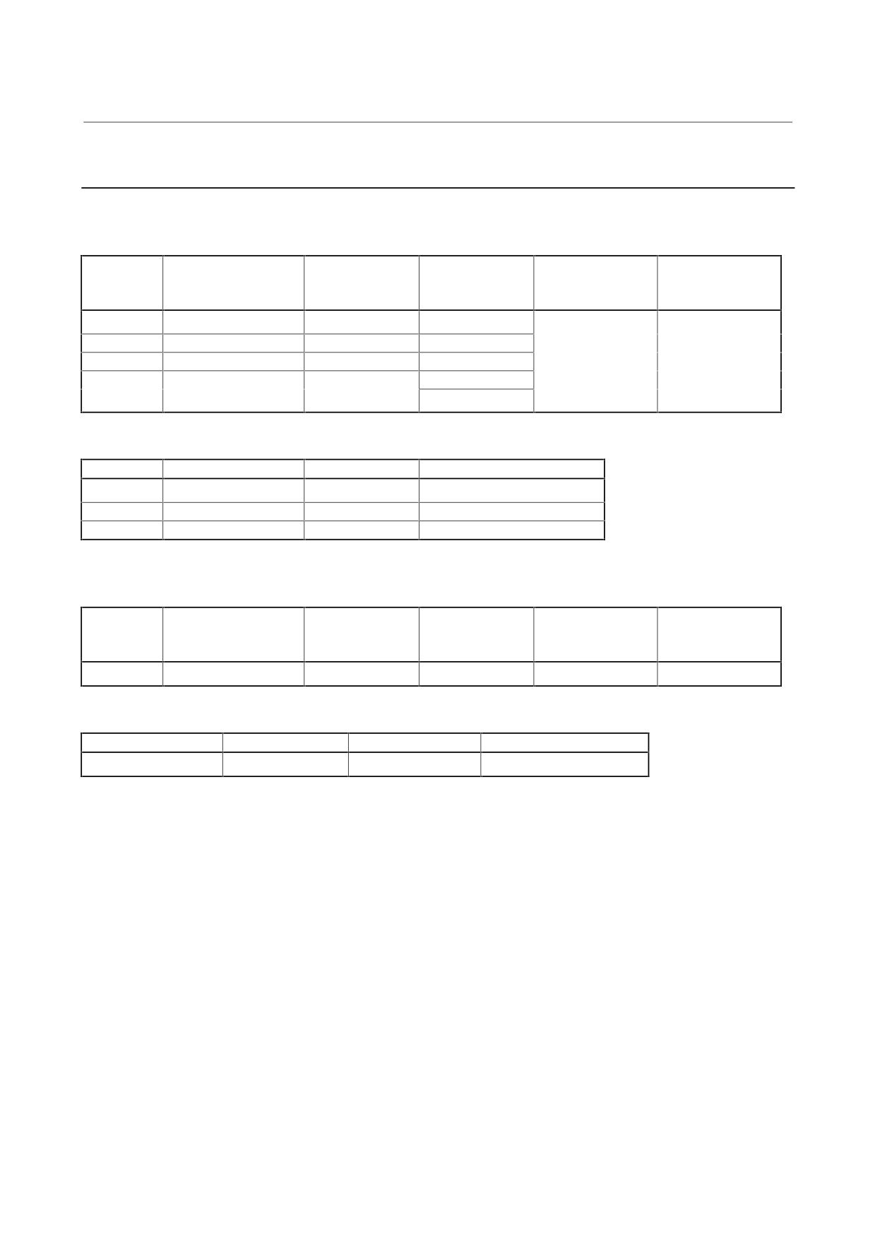
2.2.1.2 α (HV) series power supply modules
(1) Power supply modules
(PSM-HV) (400 VAC input, power
regeneration type)
Printed circuit
Wiring board
Driver board
Model
Order specification
Unit specification
board
specification
specification
specification
PSM-18HV
A06B-6091-H118
A06B-6091-C118
A20B-1006-0611
A20B-2002-0080
A16B-2202-0422
PSM-30HV
A06B-6091-H130
A06B-6091-C130
A20B-1006-0610
PSM-45HV
A06B-6091-H145
A06B-6091-C145
A20B-1006-0612
A20B-1006-0681
PSM-75HV
A06B-6091-H175
A06B-6091-C175
A20B-1007-0651
(2) Capacitor modules (PSMC-HV) (for the PSM-HV series)
Model
Order specification
Unit specification
Capacitor specification
PSMC-18HV
A06B-6083-H218
A06B-6083-C218
A42L-0001-0340
(× 2)
PSMC-30HV
A06B-6083-H230
A06B-6083-C230
A42L-0001-0314
(× 2)
PSMC-45HV
A06B-6083-H245
A06B-6083-C245
A42L-0001-0322
(× 2)
(3) Power supply module (PSMV-HV) (400 VAC input, 300 VDC
output, power regeneration type)
Printed circuit
Wiring board
Driver board
Model
Order specification
Unit specification
board
specification
specification
specification
PSMV-11HV
A06B-6098-H111
A06B-6098-C111
A20B-1007-0200
A20B-2002-0530
A16B-2203-0220
(4) AC reactor unit (PSMV-HV)
Order specification
Unit specification
AC reactor
Fuse
A06B-6098-H001
A06B-6098-C001
A81L-0001-0144
A60L-0001-0362#100U
- 9 -
2. CONFIGURATIONS
START-UP PROCEDURE
B-65165E/02
2.2.2
Servo Amplifier Modules
2.2.2.1
200-V input series
(1) Single-axis servo amplifier modules (interface: Type A/B)
Printed circuit
Order
Wiring board
Model
board
Remarks
specification
specification
specification
SVM1-2
A06B-6079-H121
A16B-2202-0742
SVM1-4
A06B-6079-H122
A16B-2202-0743
SVM1-12
A06B-6079-H101
A16B-2202-0740
SVM1-20
A06B-6079-H102
A16B-2202-0741
Enclosed in parentheses are the
A16B-2203-0450
A20B-2001-0930
SVM1-40S
A06B-6079-H103
drawing numbers of the old
(A16B-2202-0760)
specifications.
A16B-2203-0451
SVM1-40L
A06B-6079-H104
(A16B-2202-0761)
A16B-2203-0452
SVM1-80
A06B-6079-H105
(A16B-2202-0762)
A16B-2203-0454
SVM1-130
A06B-6079-H106
A20B-2001-0932
(A16B-2202-0790)
SVM1-240
A06B-6079-H107
A20B-1006-0485
A16B-2202-0990
SVM1-360
A06B-6079-H108
A20B-1006-0485
A16B-2202-0991
(2) Two-axis servo amplifier modules (interface: Type A/B)
Printed circuit
Order
Wiring board
Model
board
Remarks
specification
specification
specification
SVM2-3/3
A06B-6079-H291
A16B-2202-0753
SVM2-12/12
A06B-6079-H201
A16B-2202-0750
SVM2-12/20
A06B-6079-H202
A16B-2202-0751
SVM2-20/20
A06B-6079-H203
A16B-2202-0752
Enclosed in parentheses are the
A16B-2203-0590
A20B-2001-0931
SVM2-12/40
A06B-6079-H204
drawing numbers of the old
(A16B-2202-0770)
specifications.
A16B-2203-0591
SVM2-20/40
A06B-6079-H205
(A16B-2202-0771)
A16B-2203-0592
SVM2-40/40
A06B-6079-H206
(A16B-2202-0772)
A16B-2203-0593
SVM2-40/80
A06B-6079-H207
(A16B-2202-0773)
A16B-2203-0594
SVM2-80/80
A06B-6079-H208
A20B-2001-0933
(A16B-2202-0774)
A16B-2203-0595
SVM2-40L/40L
A06B-6079-H209
(A16B-2202-0775)
- 10 -
B-65165E/02
START-UP PROCEDURE
2. CONFIGURATIONS
(3) Three-axis servo amplifier modules (interface: Type A)
Printed circuit
Order
Wiring board
Model
board
Remarks
specification
specification
specification
SVM3-12/12/12
A06B-6079-H301
A16B-2202-0780
SVM3-12/12/20
A06B-6079-H302
A16B-2202-0781
SVM3-12/20/20
A06B-6079-H303
A16B-2202-0782
SVM3-20/20/20
A06B-6079-H304
A16B-2202-0783
A20B-2001-0940
SVM3-12/12/40
A06B-6079-H305
A16B-2202-0784
SVM3-12/20/40
A06B-6079-H306
A16B-2202-0785
SVM3-20/20/40
A06B-6079-H307
A16B-2202-0786
(4) Three-axis servo amplifier modules (interface: Type B)
Printed circuit
Order
Wiring board
Model
board
Remarks
specification
specification
specification
SVM3-12/12/12
A06B-6080-H301
A16B-2202-0780
SVM3-12/12/20
A06B-6080-H302
A16B-2202-0781
SVM3-12/20/20
A06B-6080-H303
A16B-2202-0782
SVM3-20/20/20
A06B-6080-H304
A16B-2202-0783
A20B-2001-0950
SVM3-12/12/40
A06B-6080-H305
A16B-2202-0784
SVM3-12/20/40
A06B-6080-H306
A16B-2202-0785
SVM3-20/20/40
A06B-6080-H307
A16B-2202-0786
(5) Single-axis servo amplifier module (interface: FSSB)
Printed circuit
Order
Wiring board
Model
board
Remarks
specification
specification
specification
When using HRV3, use the following
SVM1-2
A06B-6096-H121
A16B-2202-0742
boards together:
SVM1-4
A06B-6096-H122
A16B-2202-0743
A20B-2100-0540
Wiring board: A16B-2202-074X
(A20B-2100-0250)
SVM1-12
A06B-6096-H101
A16B-2202-0740
Printed circuit board:
SVM1-20
A06B-6096-H102
A16B-2202-0741
A20B-2100-054X
A16B-2203-0450
SVM1-40S
A06B-6096-H103
(A16B-2202-0760)
A16B-2203-0451
SVM1-40L
A06B-6096-H104
A20B-2100-0540
When using HRV3, use the following
(A16B-2202-0761)
(A20B-2100-0250)
boards together:
A16B-2203-0452
Wiring board: A16B-2203-045X
SVM1-80
A06B-6096-H105
(A16B-2202-0762)
Printed circuit board:
A20B-2100-054X
SVM1-130S
A06B-6096-H116
A16B-2203-0453
A16B-2203-0454
A20B-2100-0542
SVM1-130
A06B-6096-H106
(A16B-2202-0790)
(A20B-2100-0252)
SVM1-240
A06B-6096-H107
A20B-1006-0485
A16B-2203-0300
SVM1-360
A06B-6096-H108
A20B-1006-0485
A16B-2203-0301
- 11 -
2. CONFIGURATIONS
START-UP PROCEDURE
B-65165E/02
(6) Two-axis servo amplifier modules (interface: FSSB)
Printed circuit
Order
Wiring board
Model
board
Remarks
specification
specification
specification
SVM2-3/3
A06B-6096-H291
A16B-2202-0753
When using HRV3, use the following
boards together:
SVM2-12/12
A06B-6096-H201
A16B-2202-0750
A20B-2100-0541
Wiring board: A16B-2202-075X
SVM2-12/20
A06B-6096-H202
A16B-2202-0751
(A20B-2100-0251)
Printed circuit board:
SVM2-20/20
A06B-6096-H203
A16B-2202-0752
A20B-2100-054X
A16B-2203-0590
SVM2-12/40
A06B-6096-H204
(A16B-2202-0770)
A16B-2203-0591
A20B-2100-0541
SVM2-20/40
A06B-6096-H205
(A16B-2202-0771)
(A20B-2100-0251)
When using HRV3, use the following
A16B-2203-0592
SVM2-40/40
A06B-6096-H206
boards together:
(A16B-2202-0772)
Wiring board: A16B-2203-059X
A16B-2203-0593
SVM2-40/80
A06B-6096-H207
Printed circuit board:
(A16B-2202-0773)
A20B-2100-054X
A16B-2203-0594
A20B-2100-0543
SVM2-80/80
A06B-6096-H208
(A16B-2202-0774)
(A20B-2100-0253)
A16B-2203-0595
SVM2-40L/40L
A06B-6096-H209
(A16B-2202-0775)
(7) Three-axis servo amplifier modules (interface: FSSB)
Printed circuit
Order
Wiring board
Model
board
Remarks
specification
specification
specification
SVM3-12/12/12
A06B-6096-H301
A16B-2202-0780
SVM3-12/12/20
A06B-6096-H302
A16B-2202-0781
SVM3-12/20/20
A06B-6096-H303
A16B-2202-0782
SVM3-20/20/20
A06B-6096-H304
A16B-2202-0783
A20B-2100-0260
SVM3-12/12/40
A06B-6096-H305
A16B-2202-0784
SVM3-12/20/40
A06B-6096-H306
A16B-2202-0785
SVM3-20/20/40
A06B-6096-H307
A16B-2202-0786
- 12 -
B-65165E/02
START-UP PROCEDURE
2. CONFIGURATIONS
2.2.2.2
400-V input series
(1) Single-axis servo amplifier modules (interface: Type A/B)
Printed circuit
Order
Wiring board
Model
board
Remarks
specification
specification
specification
SVM1-20HV
A06B-6085-H102
A16B-2202-0800
SVM1-40HV
A06B-6085-H103
A16B-2202-0801
A20B-2001-0932
SVM1-60HV
A06B-6085-H104
A16B-2202-0802
(2) Two-axis servo amplifier modules (interface: Type A/B)
Printed circuit
Order
Wiring board
Model
board
Remarks
specification
specification
specification
SVM2-20/20HV
A06B-6085-H201
A16B-2203-0210
SVM2-20/40HV
A06B-6085-H202
A16B-2203-0211
SVM2-20/60HV
A06B-6085-H203
A16B-2203-0212
A20B-2001-0933
SVM2-40/40HV
A06B-6085-H204
A16B-2203-0213
SVM2-40/60HV
A06B-6085-H205
A16B-2203-0214
SVM2-60/60HV
A06B-6085-H206
A16B-2203-0215
(3) Single-axis servo amplifier modules (interface: FSSB)
Printed circuit
Order
Wiring board
Model
board
Remarks
specification
specification
specification
SVM1-20HV
A06B-6097-H102
A16B-2202-0800
SVM1-40HV
A06B-6097-H103
A16B-2202-0801
A20B-2100-0542
Enclosed in parentheses is the
(A20B-2100-0252)
SVM1-60HV
A06B-6097-H104
A16B-2202-0802
drawing number of the old
specification.
SVM1-80HV
A06B-6097-H105
A16B-2202-0803
SVM1-320HV
A06B-6097-H107
A20B-1007-0592
A16B-2203-0301
(4) Two-axis servo amplifier modules (interface: FSSB)
Printed circuit
Order
Wiring board
Model
board
Remarks
specification
specification
specification
SVM2-20/20HV
A06B-6097-H201
A16B-2203-0210
SVM2-20/40HV
A06B-6097-H202
A16B-2203-0211
SVM2-20/60HV
A06B-6097-H203
A16B-2203-0212
A20B-2100-0543
Enclosed in parentheses is the
SVM2-40/40HV
A06B-6097-H204
A16B-2203-0213
(A20B-2100-0253)
drawing number of the old
specification.
SVM2-40/60HV
A06B-6097-H205
A16B-2203-0214
SVM2-60/60HV
A06B-6097-H206
A16B-2203-0215
- 13 -
2. CONFIGURATIONS
START-UP PROCEDURE
B-65165E/02
2.2.3
Spindle Amplifier Modules
2.2.3.1 α series spindle amplifier modules
The order specification varies according to the detector (function)
used.
(1) α series spindle amplifier modules
(SPM) type 1 (standard
specification)
New specification
(supporting spindle HRV control), CE-marked
products
Printed circuit
Wiring board
Model
Order specification
Unit specification
board
ROM (series)
specification
specification
SPM-2.2
A06B-6102-H202#H520
A06B-6102-H202
A16B-2202-0680
A16B-2203-0500
SPM-5.5
A06B-6102-H206#H520
A06B-6102-H206
A16B-2202-0681
A16B-2203-0501
SPM-11
A06B-6102-H211#H520
A06B-6102-H211
A16B-2202-0682
A20B-1006-0486
SPM-15
A06B-6102-H215#H520
A06B-6102-H215
A20B-2902-0390
A20B-1006-0487
SPM-22
A06B-6102-H222#H520
A06B-6102-H222
A20B-2902-0390
A06B-6102-H520
A20B-1006-0488
SPM-26
A06B-6102-H226#H520
A06B-6102-H226
(9D20)
A20B-2902-0390
A16B-2203-0502
A20B-1006-0489
SPM-30
A06B-6102-H230#H520
A06B-6102-H230
A20B-2902-0390
A20B-1007-0591
SPM-45
A06B-6102-H245#H520
A06B-6102-H245
A20B-2002-0080
A20B-1007-0590
SPM-55
A06B-6102-H255#H520
A06B-6102-H255
A20B-2002-0081
- 14 -
B-65165E/02
START-UP PROCEDURE
2. CONFIGURATIONS
CE-marked products
Printed circuit
Wiring board
Model
Order specification
Unit specification
board
ROM (series)
specification(*1)
specification(*1)
A16B-2203-0330
SPM-2.2
A06B-6078-H202#H500
A06B-6078-H202
A16B-2202-0680
(A16B-2202-0430)
SPM-5.5
A06B-6078-H206#H500
A06B-6078-H206
A16B-2202-0681
A16B-2203-0331
SPM-11
A06B-6078-H211#H500
A06B-6078-H211
A16B-2202-0682
(A16B-2202-0431)
A20B-1006-0486
SPM-15
A06B-6088-H215#H500
A06B-6088-H215
(A20B-1006-0480)
A20B-2902-0390
A20B-1006-0487
SPM-22
A06B-6088-H222#H500
A06B-6088-H222
(A20B-1006-0481)
A06B-6072-H500
A20B-2902-0390
(9D00, 9D0A)
A20B-1006-0488
A16B-2203-0332
SPM-26
A06B-6088-H226#H500
A06B-6088-H226
(A20B-1006-0482)
(A16B-2202-0432)
A20B-2902-0390
A20B-1006-0489
SPM-30
A06B-6088-H230#H500
A06B-6088-H230
(A20B-1006-0483)
A20B-2902-0390
A20B-1007-0591
SPM-45
A06B-6088-H245#H500
A06B-6088-H245
(A20B-1006-0690)
A20B-2002-0080
*1
Enclosed in parentheses
are the drawing numbers of the old
specifications.
- 15 -
2. CONFIGURATIONS
START-UP PROCEDURE
B-65165E/02
Non-CE-marked products
Printed circuit
Wiring board
Model
Order specification
Unit specification
board
ROM (series)
specification
specification(*1)
A16B-2203-0330
SPM-2.2
A06B-6078-H202#H500
A06B-6078-H202
A16B-2202-0470
(A16B-2202-0430)
SPM-5.5
A06B-6078-H206#H500
A06B-6078-H206
A16B-2202-0471
A16B-2203-0331
SPM-11
A06B-6078-H211#H500
A06B-6078-H211
A16B-2202-0472
(A16B-2202-0431)
A20B-1006-0170
A06B-6072-H500
SPM-15
A06B-6088-H215#H500
A06B-6088-H215
A20B-2902-0280
(9D00, 9D0A)
A20B-1006-0171
A16B-2203-0332
SPM-22
A06B-6088-H222#H500
A06B-6088-H222
A20B-2902-0280
(A16B-2202-0432)
A20B-1006-0172
SPM-26
A06B-6088-H226#H500
A06B-6088-H226
A20B-2902-0280
Non-CE-marked products (old specifications)
Printed circuit
Wiring board
Model
Order specification
Unit specification
board
ROM (series)
specification
specification
A20B-1005-0572
SPM-15
A06B-6078-H215#H500
A06B-6078-H215
A20B-2001-0010
A20B-1005-0571
SPM-22
A06B-6078-H222#H500
A06B-6078-H222
A16B-2202-0070
A20B-2001-0010
A06B-6072-H500
A20B-2001-0150
A20B-1005-0570
(9D00, 9D0A)
SPM-26
A06B-6078-H226#H500
A06B-6078-H226
A20B-2901-0851
A20B-2001-0010
A20B-1005-0575
SPM-30
A06B-6078-H230#H500
A06B-6078-H230
A20B-2001-0010
Applicable detectors
<1> M sensor (pulse generator), position coder, magnetic sensor
<2> MZ sensor (sensor built into a motor)
*1
Enclosed in parentheses are the drawing numbers of the old
specifications.
- 16 -
B-65165E/02
START-UP PROCEDURE
2. CONFIGURATIONS
(2) α series spindle amplifier modules (SPM), type 2 (Cs contour
control/BZ sensor (separate built-in sensor) specification)
CE-marked products
Printed circuit
Wiring board
Model
Order specification
Unit specification
board
ROM (series)
specification(*1)
specification
A16B-2202-0433
SPM-2.2
A06B-6078-H302#H500
A06B-6078-H302
A16B-2202-0680
A20B-2901-0851
SPM-5.5
A06B-6078-H306#H500
A06B-6078-H306
A16B-2202-0681
A16B-2202-0434
SPM-11
A06B-6078-H311#H500
A06B-6078-H311
A16B-2202-0682
A20B-2901-0851
A20B-1006-0486
SPM-15
A06B-6088-H315#H500
A06B-6088-H315
(A20B-1006-0480)
A20B-2902-0390
A20B-1006-0487
SPM-22
A06B-6088-H322#H500
A06B-6088-H322
(A20B-1006-0481)
A06B-6072-H500
A20B-2902-0390
(9D00, 9D0A)
A20B-1006-0488
A16B-2202-0435
SPM-26
A06B-6088-H326#H500
A06B-6088-H326
(A20B-1006-0482)
A20B-2901-0851
A20B-2902-0390
A20B-1006-0489
SPM-30
A06B-6088-H330#H500
A06B-6088-H330
(A20B-1006-0483)
A20B-2902-0390
A20B-1007-0591
SPM-45
A06B-6088-H345#H500
A06B-6088-H345
(A20B-1006-0690)
A20B-2002-0080
Non-CE-marked products
Printed circuit
Wiring board
Model
Order specification
Unit specification
board
ROM (series)
specification
specification
A16B-2202-0433
SPM-2.2
A06B-6078-H302#H500
A06B-6078-H302
A16B-2202-0470
A20B-2901-0851
SPM-5.5
A06B-6078-H306#H500
A06B-6078-H306
A16B-2202-0471
A16B-2202-0434
SPM-11
A06B-6078-H311#H500
A06B-6078-H311
A16B-2202-0472
A20B-2901-0851
A20B-1006-0170
A06B-6072-H500
SPM-15
A06B-6088-H315#H500
A06B-6088-H315
A20B-2902-0280
(9D00, 9D0A)
A20B-1006-0171
A16B-2202-0435
SPM-22
A06B-6088-H322#H500
A06B-6088-H322
A20B-2902-0280
A20B-2901-0851
A20B-1006-0172
SPM-26
A06B-6088-H326#H500
A06B-6088-H326
A20B-2902-0280
*1
Enclosed in parentheses
are the drawing
numbers of the old
specifications.
- 17 -
2. CONFIGURATIONS
START-UP PROCEDURE
B-65165E/02
Non-CE-marked products (old specification)
Printed circuit
Wiring board
Model
Order specification
Unit specification
board
ROM (series)
specification
specification
A20B-1005-0572
SPM-15
A06B-6078-H315#H500
A06B-6078-H315
A20B-2001-0010
A20B-1005-0571
SPM-22
A06B-6078-H322#H500
A06B-6078-H322
A16B-2202-0160
A20B-2001-0010
A06B-6072-H500
A20B-2001-0140
A20B-1005-0570
(9D00, 9D0A)
SPM-26
A06B-6078-H326#H500
A06B-6078-H326
A20B-2901-0851
A20B-2001-0010
A20B-1005-0575
SPM-30
A06B-6078-H230#H500
A06B-6078-H330
A20B-2001-0010
Applicable detectors
<1> M sensor (pulse generator) + BZ sensor (separate built-in
sensor) (use of position coder signals only)
<2> High-resolution magnetic pulse coder (for motor only)
<3> High-resolution magnetic pulse coder
(for motor and
spindle)
<4> High-resolution position coder + high-resolution magnetic
pulse coder (for motor only)
- 18 -
B-65165E/02
START-UP PROCEDURE
2. CONFIGURATIONS
(3) α series spindle amplifier modules
(SPM), type
3 (spindle
switching control/differential speed control specification)
CE-marked products
Printed circuit
Wiring board
Model
Order specification
Unit specification
board
ROM (series)
specification(*1)
specification
A20B-1006-0484
SPM-11
A06B-6088-H411#H500
A06B-6088-H411
A20B-2902-0390
A20B-1006-0486
SPM-15
A06B-6088-H415#H500
A06B-6088-H415
(A20B-1006-0480)
A20B-2902-0390
A20B-1006-0487
SPM-22
A06B-6088-H422#H500
A06B-6088-H422
(A20B-1006-0481)
A20B-2902-0390
A16B-2202-0440
A06B-6072-H500
A20B-1006-0488
A20B-2001-0700
(9D00, 9D0A)
SPM-26
A06B-6088-H426#H500
A06B-6088-H426
(A20B-1006-0482)
A20B-2901-0851
A20B-2902-0390
A20B-1006-0489
SPM-30
A06B-6088-H430#H500
A06B-6088-H430
(A20B-1006-0483)
A20B-2902-0390
A20B-1007-0591
SPM-45
A06B-6088-H445#H500
A06B-6088-H445
(A20B-1006-0690)
A20B-2002-0080
Non-CE-marked products
Printed circuit
Wiring board
Model
Order specification
Unit specification
board
ROM (series)
specification
specification
A20B-1005-0574
SPM-11
A06B-6078-H411#H500
A06B-6078-H411
A20B-2001-0010
A20B-1005-0572
SPM-15
A06B-6078-H415#H500
A06B-6078-H415
A20B-2001-0010
A16B-2202-0160
A20B-1005-0571
A06B-6072-H500
SPM-22
A06B-6078-H422#H500
A06B-6078-H422
A20B-2001-0140
A20B-2001-0010
(9D00, 9D0A)
A20B-2901-0851
A20B-1005-0570
SPM-26
A06B-6078-H426#H500
A06B-6078-H426
A20B-2001-0010
A20B-1005-0575
SPM-30
A06B-6078-H430#H500
A06B-6078-H430
A20B-2001-0010
Applicable functions
<1> Spindle switching
control
(switching
of speed only
or
switching of speed and position)
<2> Spindle switching control (switching of MZ sensor (built-in
sensor))
<3> Differential speed control
(position coder signal input
circuit)
*1
Enclosed in parentheses are the drawing numbers of the old
specifications.
- 19 -
2. CONFIGURATIONS
START-UP PROCEDURE
B-65165E/02
(4) α series spindle amplifier modules (SPM), type 4 (α sensor Cs
contour control)
New specification
(supporting spindle HRV control), CE-marked
products
Printed circuit
Wiring board
Model
Order specification
Unit specification
board
ROM (series)
specification
specification
A16B-2203-0503
SPM-2.2
A06B-6102-H102#H520
A06B-6102-H102
A16B-2202-0680
A20B-2902-0620
SPM-5.5
A06B-6102-H106#H520
A06B-6102-H106
A16B-2202-0681
A16B-2203-0504
SPM-11
A06B-6102-H111#H520
A06B-6102-H111
A16B-2202-0682
A20B-2902-0620
A20B-1006-0486
SPM-15
A06B-6102-H115#H520
A06B-6102-H115
A20B-2902-0390
A20B-1006-0487
SPM-22
A06B-6102-H122#H520
A06B-6102-H122
A20B-2902-0390
A06B-6102-H520
A20B-1006-0488
(9D20)
SPM-26
A06B-6102-H126#H520
A06B-6102-H126
A20B-2902-0390
A16B-2203-0505
A20B-1006-0489
A20B-2902-0620
SPM-30
A06B-6102-H130#H520
A06B-6102-H130
A20B-2902-0390
A20B-1007-0591
SPM-45
A06B-6102-H145#H520
A06B-6102-H145
A20B-2002-0080
A20B-1007-0590
SPM-55
A06B-6102-H155#H520
A06B-6102-H155
A20B-2002-0081
- 20 -
B-65165E/02
START-UP PROCEDURE
2. CONFIGURATIONS
CE-marked products
Printed circuit
Wiring board
Model
Order specification
Unit specification
board
ROM (series)
specification(*1)
specification(*1)
A16B-2202-0433
Overall revision 16E
SPM-2.2
A06B-6078-H102#H500
A06B-6078-H102
A16B-2202-0680
or later
A20B-2902-0620
(A20B-2902-0610)
A16B-2202-0434
SPM-5.5
A06B-6078-H106#H500
A06B-6078-H106
A16B-2202-0681
Overall revision 16E
or later
SPM-11
A06B-6078-H111#H500
A06B-6078-H111
A16B-2202-0682
A20B-2902-0620
(A20B-2902-0610)
A20B-1006-0486
SPM-15
A06B-6088-H115#H500
A06B-6088-H115
(A20B-1006-0480)
A06B-6072-H500
A20B-2902-0390
(9D00, 9D0A)
A20B-1006-0487
SPM-22
A06B-6088-H122#H500
A06B-6088-H122
(A20B-1006-0481)
A20B-2902-0390
A16B-2202-0435
A20B-1006-0488
Overall revision 13C
SPM-26
A06B-6088-H126#H500
A06B-6088-H126
(A20B-1006-0482)
or later
A20B-2902-0390
A20B-2902-0620
A20B-1006-0489
(A20B-2902-0610)
SPM-30
A06B-6088-H130#H500
A06B-6088-H130
(A20B-1006-0483)
A20B-2902-0390
A20B-1007-0591
SPM-45
A06B-6088-H145#H500
A06B-6088-H145
(A20B-1006-0690)
A20B-2002-0080
Applicable detectors
<1> MZ sensor (sensor built into a motor)
<2> MZ sensor (sensor built into a motor) + BZ sensor (separate
built-in sensor)
*1
Enclosed in parentheses are the drawing numbers of the old
specifications.
- 21 -
2. CONFIGURATIONS
START-UP PROCEDURE
B-65165E/02
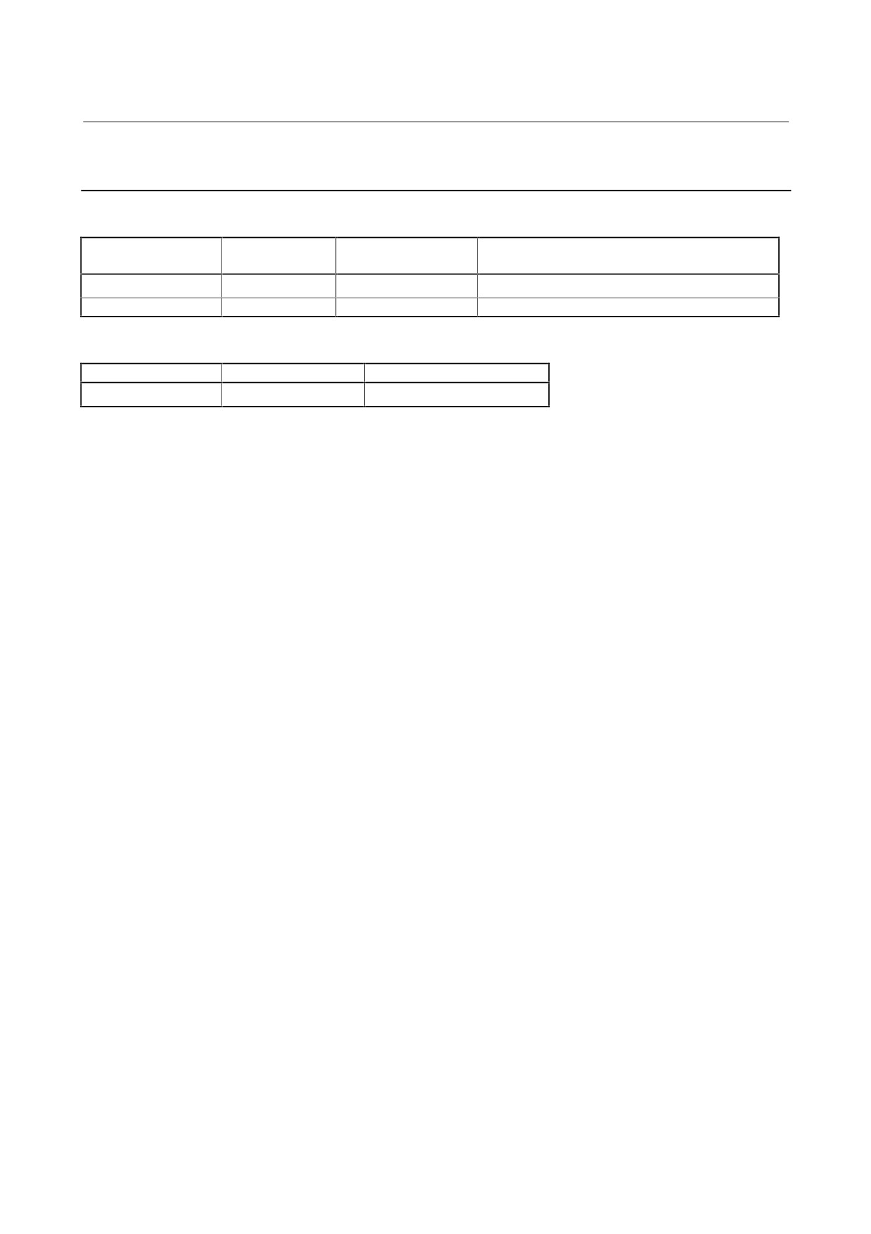
2.2.4
Power-Failure Backup Modules
(1) Power-failure backup modules
Wiring board
Printed circuit board
Order specification
Remarks
specification
specification
A06B-6077-H001
A16B-2203-0360
A20B-2002-0790
Without the control power supply backup function
A06B-6077-H002
A16B-2203-0510
A20B-2003-0020
With the control power supply backup function
(2) Sub-module C (auxiliary capacitor unit)
Order specification
Unit specification
Capacitor specification
A06B-6077-H010
A06B-6077-C010
A42L-0001-0375
(× 2)
- 22 -
3. START-UP PROCEDURE
START-UP PROCEDURE
B-65165E/02
3.1
START-UP PROCEDURE (OVERVIEW)
Make sure that the specifications of the CNC, servo motors, servo
amplifiers, and other units you received are exactly what you ordered,
and these units are connected correctly. Then, turn on the power.
(1)
Before turning on the circuit breaker, check the power supply
voltage connected.
→ See Section 3.2.
(2)
Some types of PSM, SVM, and SPM require settings before the
system can be used. So check whether you must make settings.
→ See Section 3.3.
(3)
Turn on the power, and set initial parameters on the CNC.
For the initialization of servo parameters, refer to the following
manual:
FANUC AC SERVO MOTOR α series Parameter Manual
(B-65150E)
For the initialization of spindle parameters, refer to the following
manual:
FANUC AD SPINDLE MOTOR α series Parameter Manual
(B-65160E)
(4)
For start-up adjustment and troubleshooting, see Chapter 4.
• Method of using optional wiring boards for adjustment of the
PSM, SVM, and SPM
• Spindle sensor adjustment values
- 24 -
B-65165E/02
START-UP PROCEDURE
3. START-UP PROCEDURE
3.2
CONNECTING THE POWER
3.2.1
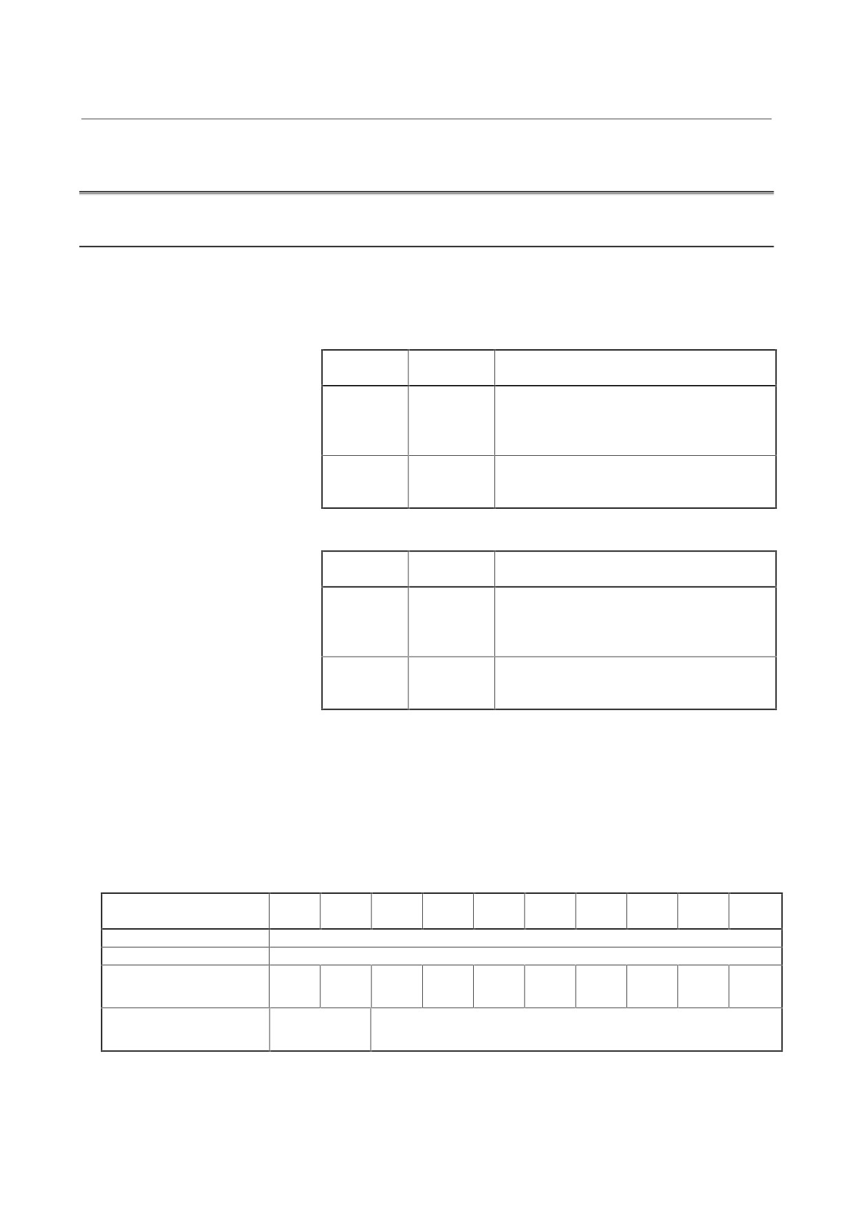
Checking The Voltage And Capacity Of The Power
Before connecting the power, you should measure the AC power
voltage.
Table 3.2.1(1) Action for the AC power (200-V input type)
AC power
Nominal
Action
voltage
voltage
170 to 220 V
200 V
These power lines can be connected directly to
210 to 253 V
230 V
the system.
Note) If the voltage is below the rated value, the
rated output may not be obtained.
254 V or
380 to 550 V
This power line must be connected through an
more
insulation transformer to step down the voltage
to 200 V.
Table 3.2.1(2) Action for the AC power (400-V input type)
AC power
Nominal
Action
voltage
voltage
340 to 440 V
400 V
These power lines can be connected directly to
391 to 506 V
460 V
the system.
Note) If the voltage is below the rated value, the
rated output may not be obtained.
507 V or
480 to 550 V
This power line must be connected through an
more
insulation transformer to step down the voltage
to 400 V.
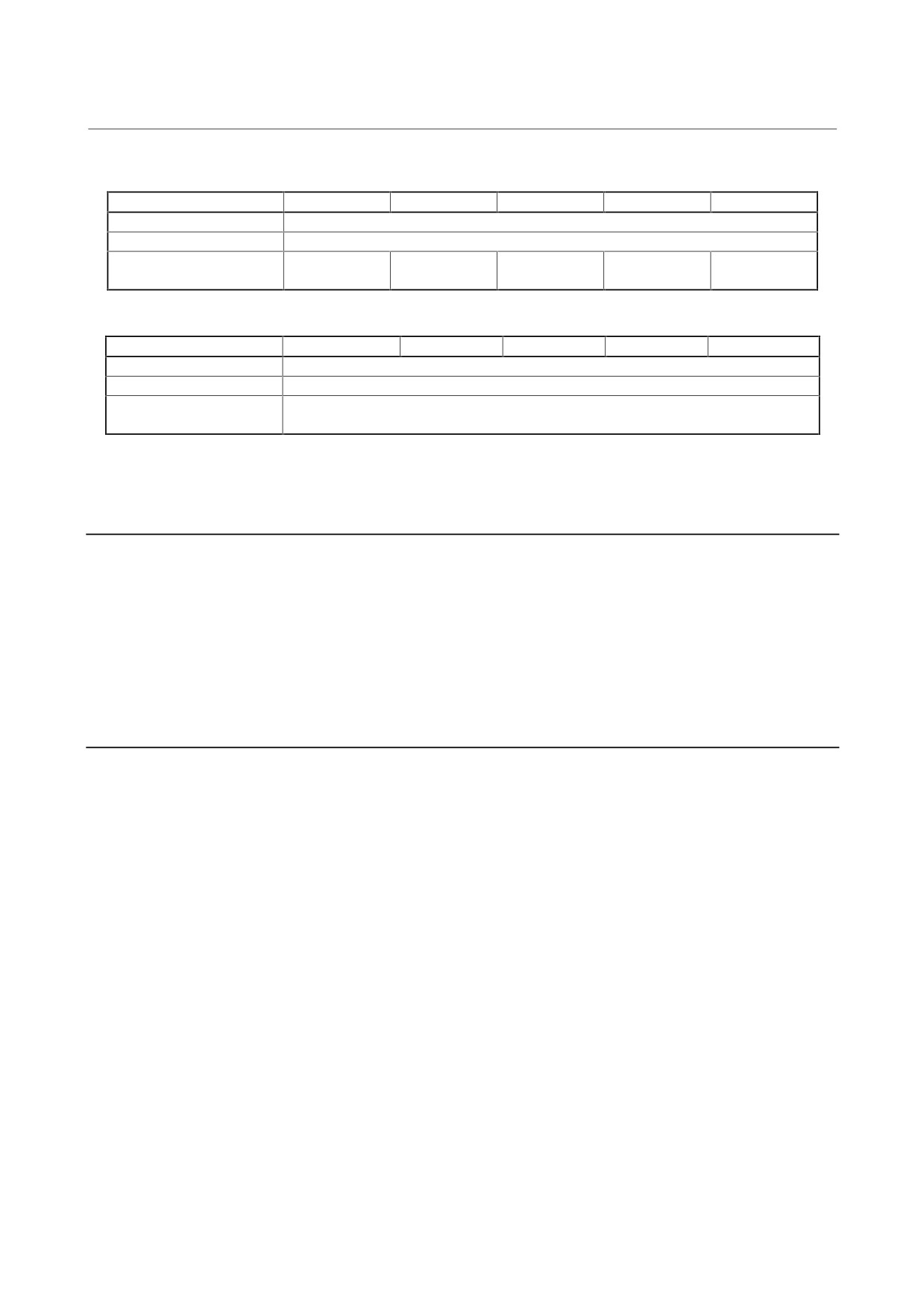
Table 3.2.1 (3) to (5) list the input power specification for the power
supply module. Use a power source with sufficient capacity so that the
system will not malfunction due to a voltage drop even at a time of peak
load. Make sure that the AC power voltage value including voltage
fluctuation at a time of peak load is within the range specified in the
above table.
Table 3.2.1 (3) AC power voltage specifications
PSMR
PSMR
PSM
PSM
PSM
PSM
PSM
PSM
PSM
PSM
Model
-3
-5.5
-5.5
-11
-15
-26
-30
-37
-45
-55
Nominal voltage rating
200/220/230 VAC -15%, +10%
Power source frequency
50/60 Hz ±1 Hz
Power source capacity (for
5
12
9
17
22
37
44
53
64
79
the main circuit) [kVA]
Power source capacity (for
0.5
0.7
the control circuit) [kVA]
- 25 -
3. START-UP PROCEDURE
START-UP PROCEDURE
B-65165E/02
Table 3.2.1 (4) AC power voltage specifications (for the main circuit)
Model
PSMV-11HV
PSM-18HV
PSM-30HV
PSM-45HV
PSM-75HV
Nominal voltage rating
400/460 VAC -15%, +10%
Power source frequency
50/60 Hz ±1 Hz
Power source capacity
31
26
44
64
107
[kVA]
Table 3.2.1 (5) AC power voltage specifications (for the control circuit)
Model
PSMV-11HV
PSM-18HV
PSM-30HV
PSM-45HV
PSM-75HV
Nominal voltage rating
200/220/230 VAC -15%, +10%
Power source frequency
50/60 Hz ±1 Hz
Power source capacity
0.7
[kVA]
3.2.2
Connecting A Protective Ground
Refer to the items in Chapter 5, "Installation," in "FANUC SERVO
AMPLIFIER α series Descriptions" B-65162E, and check that the
protective ground line is connected correctly.
3.2.3
Selecting The Ground Fault Interrupter That Matches The
Leakage Current
Refer to the items in Chapter 5, "Installation," in "FANUC SERVO
AMPLIFIER α series Descriptions" B-65162E, and check that a
correct ground fault interrupter is selected.
- 26 -
B-65165E/02
START-UP PROCEDURE
3. START-UP PROCEDURE
3.3
SETTING THE PRINTED-CIRCUIT BOARD
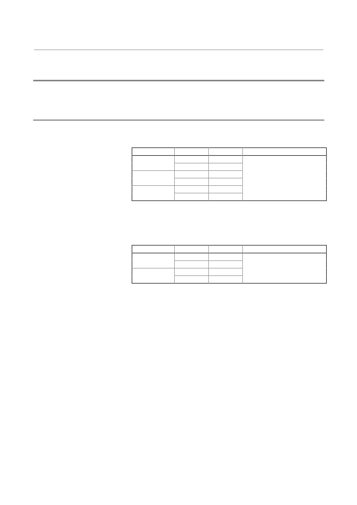
Before supplying power, set the printed-circuit board as listed below.
3.3.1
Power Supply Module
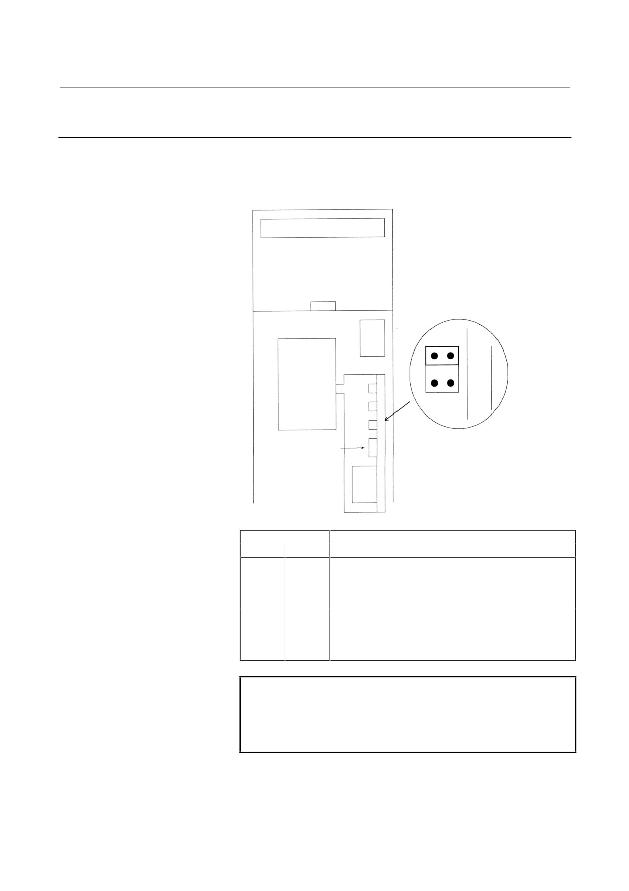
Checking the DIP switch setting
(1) CE-marked products
Model
DIP switch
Position
Description
PSM-5.5 to 11
S1
SHORT
Do not change the setting of the
S2
OPEN(*1)
DIP switches because they were
PSM-15 to 55
S1
SHORT
already set at the factory.
S2
OPEN
PSM-18HV to
S1
SHORT
75HV
S2
OPEN
*1
This setting has been made in shipments after January, 2000. In
earlier products, this switch was factory-set to SHORT.
(2) Non-CE-marked products
Model
DIP switch
Position
Description
PSM-5.5 to 11
S1
SHORT
Do not change the setting of the
S2
OPEN
DIP switches because they were
PSM-15 to 30
S1
SHORT
already set at the factory.
S2
OPEN
- 27 -
3. START-UP PROCEDURE
START-UP PROCEDURE
B-65165E/02
3.3.2
Servo Amplifier Module
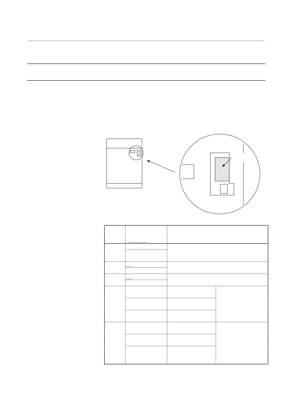
(1) Checking the jumper plug setting (for SVM1 and SVM2)
Set the servo amplifier module to either interface type A or B with
the jumper plugs.
FANUC
S1
S2
Move the jumper plugs as required. If
FUSE
you cannot pull out a jumper plug with
your thumb and finger, use long-nose
pliers or the like.
Jumper plug
Description
S1
S2
SHORT
OPEN
With this setting, the servo amplifier module can operate
with the CNC (such as FS0, FS15, FS16, FS18, or PM-
D) designed for operation with interface type A. In this
case the JV*B connector is used.
OPEN
SHORT
With this setting, the servo amplifier module can operate
with the CNC (such as FS20 or FS21-G) designed for
operation with interface type B. In this case the JS*B
and JF* connectors are used.
NOTE
There is no jumper plug or DIP switch on the three-
axis servo amplifier module. The specification of the
servo amplifier module determines the type (A or B)
of the interface with which it can operate.
(2) Mounting the batteries for the ABS pulse coder
See Sec. I.5.1.
- 28 -
B-65165E/02
START-UP PROCEDURE
3. START-UP PROCEDURE
3.3.3
Spindle Amplifier Module
3.3.3.1 α series spindle amplifier module (SPM)
This type of modules do not have a DIP switch except the modules of
which specification drawing numbers are A06B-6072-H***#00xx (D
series spindle amplifier modules) and A06B-6078-H***#H5xx (non-
CE-marked α series spindle amplifier modules).
Location of the DIP switch
DIP switch
S7
SW
S1
F2
5A
Switch setting
DIP
(factory-set to the
Description
switch
underlined position)
S1
ON
If two SPMs are connected to one serial interface
OFF
cable, S1 is set to ON in one SPM, and to OFF in
the other.
S2
ON
If an analog filter is used at the load meter output,
OFF
S2 is set to ON. If not, it is set to OFF.
S3
ON
If an analog filter is used at the speedometer
OFF
output, S3 is set to ON. If not, it is set to OFF.
S4
S4:ON, S5:OFF
Reference switch of
Reference switch
S5
NPN type (pull up)
(external reference signal
S4:OFF, S5:OFF
Reference switch of
receive function) setting
PNP type (pull down)
for the main spindle
S4:OFF, S5:OFF
The external reference
signal receive function.
S6
S6:ON, S7:OFF
Reference switch of
Reference switch
S7
NPN type (pull up)
(external reference signal
S6:OFF, S7:OFF
Reference switch of
receive function) setting
PNP type (pull down)
for the sub-spindle
S6:OFF, S7:OFF
The external reference
signal receive function
is not used.
- 29 -
3. START-UP PROCEDURE
START-UP PROCEDURE
B-65165E/02
3.3.3.2 α (HV) series spindle amplifier module (SPM-HV)
This module does not have a DIP switch.
3.3.3.3 αC series spindle amplifier module (SPMC)
This module does not have a DIP switch.
- 30 -
B-65165E/02
START-UP PROCEDURE
3. START-UP PROCEDURE
3.4
INITIALIZING SERVO PARAMETERS
(1) Servo amplifier module
For the initialization of servo parameters, refer to the following
manual:
FANUC AC SERVO MOTOR α series Parameter Manual
(B-65150E)
(2) Spindle amplifier module
For the initialization of spindle parameters, refer to the following
manual:
FANUC AC SPINDLE MOTOR α series Parameter Manual
(B-65160E)
- 31 -
4. CONFIRMATION OF
THE OPERATION
START-UP PROCEDURE
B-65165E/02
4
CONFIRMATION OF THE OPERATION
- 32 -
4. CONFIRMATION OF
B-65165E/02
START-UP PROCEDURE
THE OPERATION
4.1
POWER SUPPLY MODULE
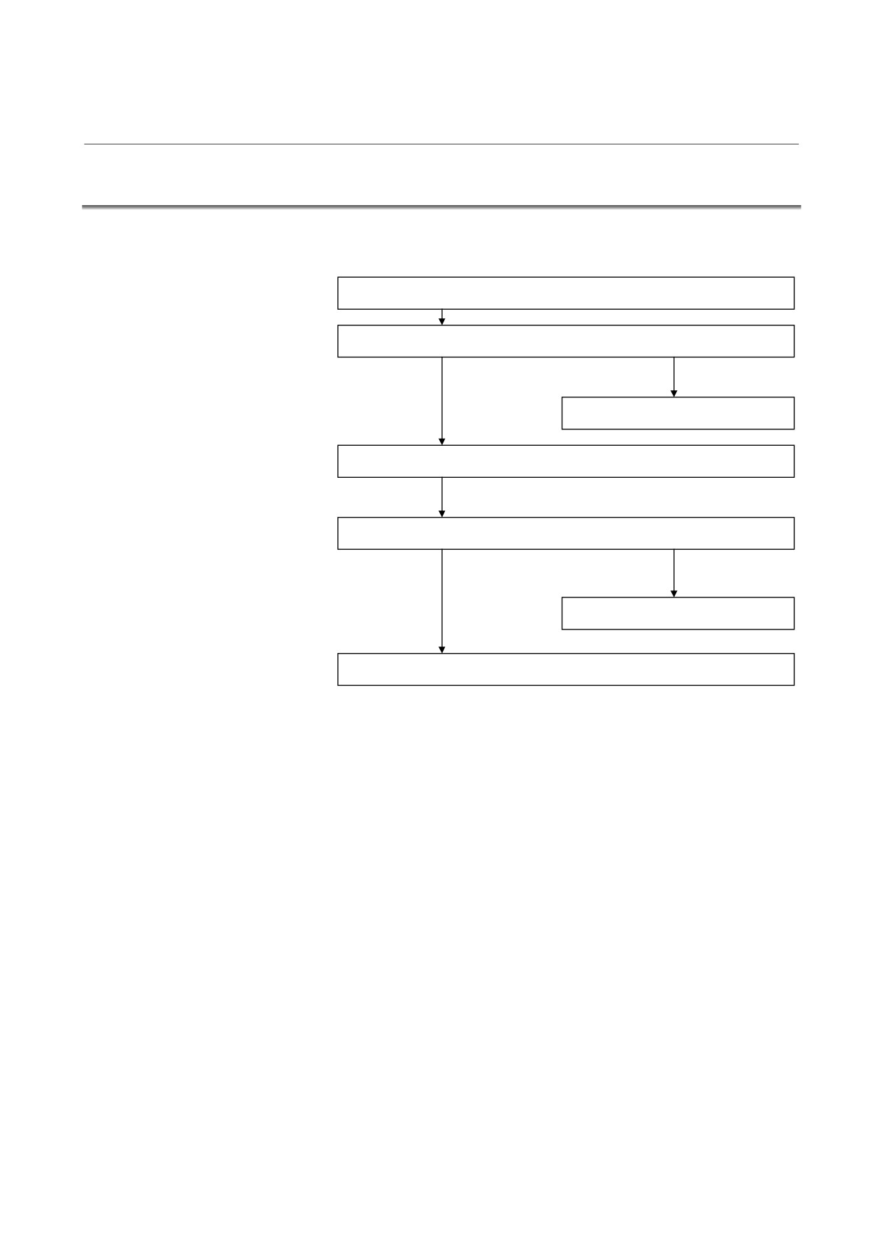
Check each item according to the procedure described below.
1. Supply control power (200 VAC) to the power supply module.
2. Check the STATUS LEDs. See Section 4.1.3.
OK
Alarm occurs.
See Section 3.1 of Part II.
3. Release the system from emergency stop state.
4. Make sure that the MCC is turned on.
OK
NG
See Subsec. 4.1.5.
5. Check the operation of the servo and spindle motors.
- 33 -
4. CONFIRMATION OF
THE OPERATION
START-UP PROCEDURE
B-65165E/02
4.1.1
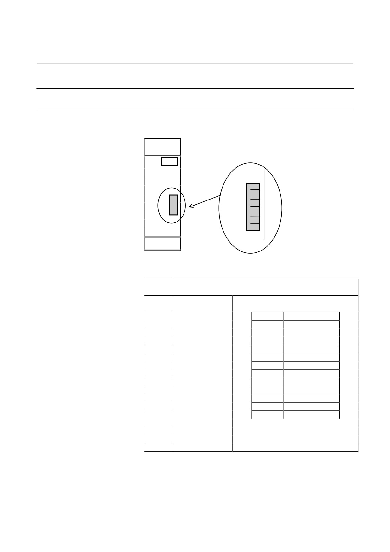
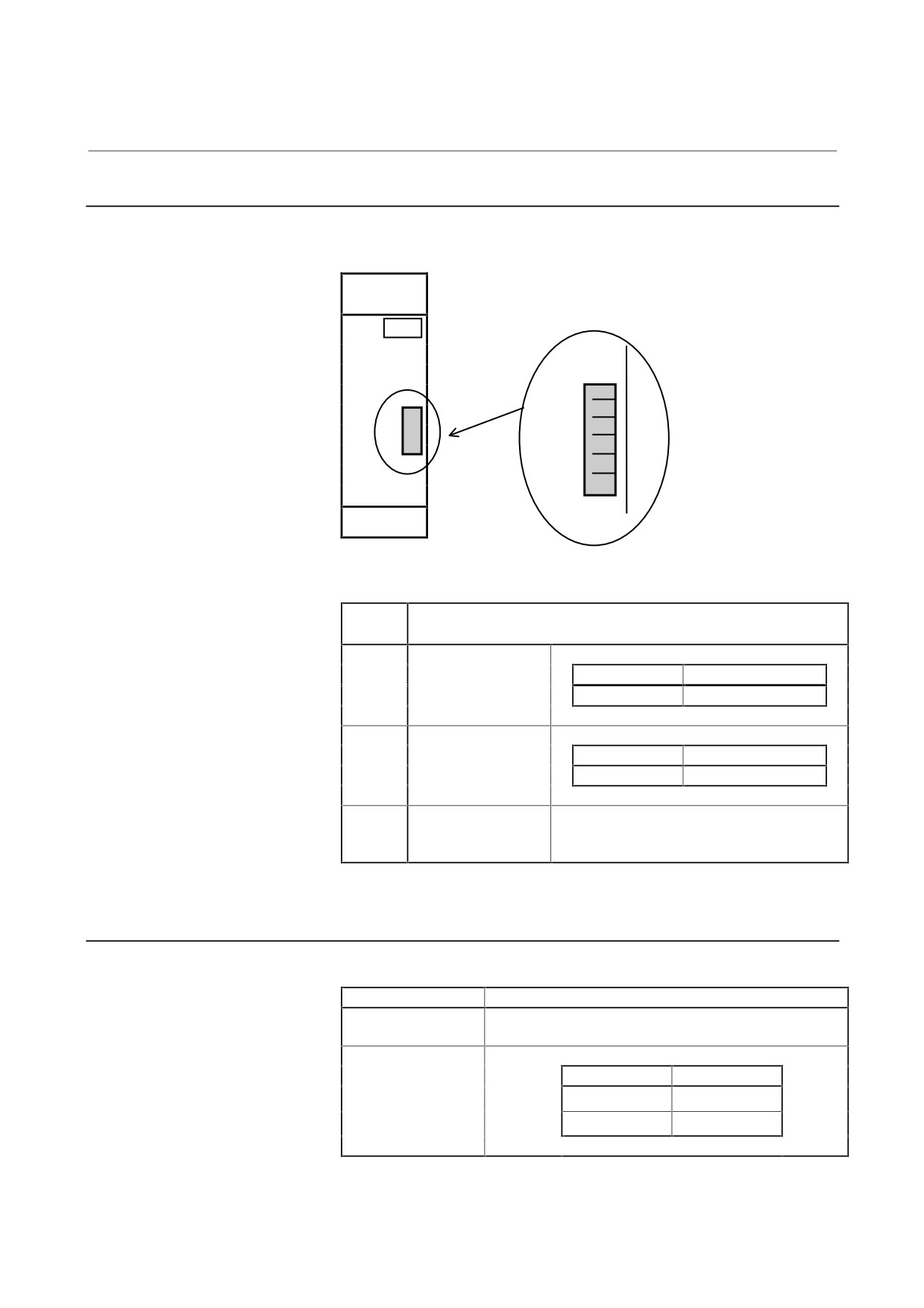
Check Terminal On The Printed-circuit Board
4.1.1.1 PSM, PSM-HV
Location of the check terminal
IR
IS
+24V
+5V
0V
Table 4.1.1.1 Check terminal
Check
Description
terminal
IR
Phase L1 (phase R)
The current is positive when it is input to the
current
amplifier.
Model
Amount of current
IS
Phase L2 (phase S)
PSM-5.5
37.5A/1V
current
PSM-11
37.5A/1V
PSM-15
50A/1V
PSM-26
75A/1V
PSM-30
100A/1V
PSM-37
100A/1V
PSM-45
150A/1V
PSM-55
150A/1V
PSM-18HV
37.5A/1V
PSM-30HV
50A/1V
PSM-45HV
75A/1V
PSM-75HV
100A/1V
+24V
Control power
+5V
0V
- 34 -
4. CONFIRMATION OF
B-65165E/02
START-UP PROCEDURE
THE OPERATION
4.1.1.2 PSMV-HV
Location of check terminals
IDC
VDC
+24V
+5V
0V
Table 4.1.1.2 Check terminals
Check
Description
terminal
IDC
DC link current
Model
Amount of current
PSMV-11HV
50 A/1 V
VDC
DC link voltage
Model
Amount of voltage
PSMV-11HV
100 V/1 V
+24V
Control power
+5V
0V
4.1.2
Checking The Power Supply Voltages
Table 4.1.2 Checking the power supply voltages
Measurement item
Check method
AC power line
Check on L1, L2, and L3 at terminal board TB2.
voltage
See Section 3.2.1.
Control power
Check on the check terminals.
voltage
Check terminal
Rating
+24V - 0V
24 V ±5%
+5V - 0V
5 V ±5%
- 35 -