FANUC AC SERVO MOTOR ai series, AC SPINDLE MOTOR ai series, SERVO AMPLIFIER ai series. MAINTENANCE MANUAL - page 9
3. PERIODIC MAINTENANCE OF SERVO AMPLIFIER
3.1.
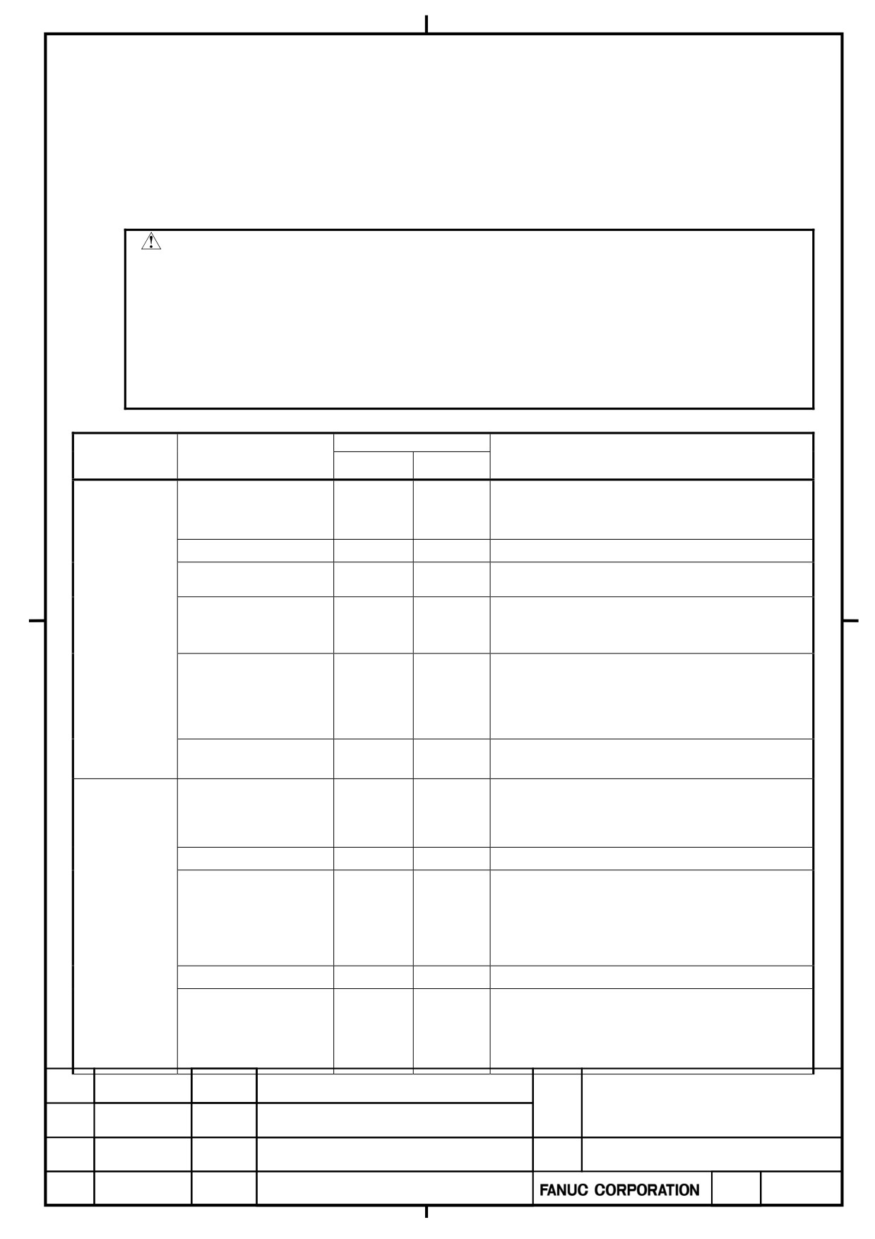
PERIODIC MAINTENANCE ITEM
To use the servo amplifier for a long time and keep its high performance and reliability, you should perform
maintenance and inspection on it routinely.
Note
・ The methods of maintenance differ for the machine. Moreover, a scheduled inspection and
fixed cleaning according to a user depending on a machine may be difficult. Please prepare
the procedure which can perform a priodicmaintenance and cleaning certainly after asking a
machine maker about an unknown point.
・ Please use a machine within the limits of the specification specified by a machine maker.
When how to use besides specification is adopted, there is a possibility of shortening the life
of servo amplifier or becoming the cause of an obstacle
Inspection cycle
Inspection
Inspection
Criterion
target
item
Routine
Periodic
Surroundings of the power magnetics cabinet:
Ambient temperature
○
0 to45°C
Inside of power magnetics cabinet: 0 to 55°C
Humidity
○
90%RH or lower (no condensation allowed)
No dust or oil mist shall be on and around the
Dust and Oil mist
○
servo amplifier.
Whether the cooling air path is free from an
Cooling air path
○
obstacle.
Environment
Whether the cooling fan motor is working.
(1) There shall be no abnormal sound or
vibration
Abnormal vibration
○
that has not be experienced so far.
and noise
(2) Any vibration on and around the amplifier
shall not be over 0.5 G.
200V input model: 200 to 240 V.
Power supply voltage
○
400V input model: 400 to 240 V.
Whether there is dust or oil mist on the
amplifier.
General
○
Whether the amplifier generates abnormal
sound or odor.
Screw
○
There shall be no loose screw
(1) The motor shall not generate abnormal
vibration
Fan motor
or sound.
○
(note 1) (note 2)
Amplifier
(2) There shall be no dust or oil mist on the
motor.
Connector
○
Whether there is a loose connector.
1) Whether there is a sign of past heat
generation.
Cable
○
(2) Whether there is a deteriorated sheath
(discolored or cracked).
α+ series SERVO AMPLIFIER
TITLE
for 30+-B Start-up and
Maintenance manual
B-65285EN/03-02/04
NO.
EDT.
DATE
DESIG.
DESCRIPTION
PAGE
60 / 79
Battery for absolute
The battery low alarm of an absolute pulse
CNC
pulsecorder
○
coder is not displayed on a mechanical control
(note 2)
board or a screen.
Magnetic
The magnetic contactor shall not rattle or
○
contactor
chatter.
External
Ground fault
device
○
The interrupter shall be able to trip.
interrupter
AC reactor
○
There shall be no hum.
(note 1) Generally, fan motors are periodic-replacement parts.
If a fan motor for a servo amplifier does not work, the amplifier will not get broken immediately. However, you should
inspect the fan motor constantly and replace it in a preventive manner.
(note 2) Since the fan motor and battery are periodic maintenance parts, Fanuc recommend preparation of spare parts.
α+ series SERVO AMPLIFIER
TITLE
for 30+-B Start-up and
Maintenance manual
B-65285EN/03-02/04
NO.
EDT.
DATE
DESIG.
DESCRIPTION
PAGE
61 / 79
3.2.
INSULATION DETERIORATION DETECTION FUNCTION
The α+ servo amplifier for the 30+-B series includes an insulation deterioration detection function, which can
detect a sign of insulation deterioration in motor windings and power wires automatically and accurately.
This function can use the voltage charged in the servo amplifier DC link to measure automatically the insulation
resistance between the motor or power cable and a ground immediately after the servo amplifier has shifted from a
servo-on state to an emergency stop state, thereby checking for insulation deterioration.
If an insulation resistance of 10 Mȍ or below is detected, a warning is issued.
3.2.1
How to Use
(1) To use the insulation deterioration detection function, set the parameters
listed below.
Parameter No.
Enabling/disabling the function (axis by axis)
Servo amplifier
No2429#0
0: Disable for SV (default)/1: Enable for SV
Spindle amplifier
No4549#0
0: Disable for SP (default)/1: Enable for SP
(2) Measuring the insulation resistance requires charging the DC link voltage.
So, keep the amplifier released from an emergency stop for at least 5
seconds before measurement. This is unnecessary when the machine is
working normally before measurement.
(3) The measurement of insulation resistance start by inputting the emergency
stop(*ESP) to connector CX4 of common power supply (PS) after the DC
link voltage is charged.
3.2.2
How to Check
(1) If insulation deterioration is detected, “LKG” in the lower section of the
CNC screen blinks.
(2) Measurement results can be viewed on the “LEAKAGE DETECTION
MONITOR” screen of the CNC.
3.2.3
Action
If insulation deterioration is detected, measure the insulation resistance of motor and power cables separately with
a megohmmeter to see which has a deteriorated insulation, the motor or power cable.
Then, replace the motor or power cable whichever is relevant.
α+ series SERVO AMPLIFIER
TITLE
for 30+-B Start-up and
Maintenance manual
B-65285EN/03-02/04
NO.
EDT.
DATE
DESIG.
DESCRIPTION
PAGE
62 / 79
3.2.4
Other Notes
(1) No insulation resistance is measured in the following cases:
- The servo amplifier enters an emergency stop state again before entering a
ready state.
- The servo amplifier is released from an emergency stop state during
insulation deterioration checks.
(2) Continuing a long-term operation with insulation deteriorated may cause
the machine to stop because of the ground fault interrupter tripping or an
alarm occurring. If insulation deterioration is detected, replace the relevant
motor or power cable as soon as possible.
(3) No accurate measurement can be made while the motor is running. So, no
measurement will be made even in an emergency stop state, for example, if
the spindle motor is rotating through inertia.
WARNING
Insulation resistance measurement starts when the emergency stop signal (*ESP) applied to the
connector CX4 of the common power supply (PS) represents an emergency stop state. During
insulation resistance measurement, the voltage charged in the DC link is applied to the motor.
Do not touch the motor during measurement to avoid getting electrical shocks. Insulation
resistance measurement begins 6 seconds after the emergency stop state has been entered.
α+ series SERVO AMPLIFIER
TITLE
for 30+-B Start-up and
Maintenance manual
B-65285EN/03-02/04
NO.
EDT.
DATE
DESIG.
DESCRIPTION
PAGE
63 / 79
3.2.5
Change of warning level of insulation deterioration detection
Warning level of insulation resistance can be changed by parameter setting, when following software editions are
applied. (The level was 10MΩ as fixed value in the former specification.)
[Compatible software series and editions]
Servo Software
CNC for series 30+-B Standard series Series 90G0/19.0 and subsequent editions
CNC for series 30+-B Series for Learning Control Series 90G3/05.0 and subsequent editions
CNC for series 0+-D
1 path system Series 90C8/04.0 and subsequent editions
2 path system Series 90E8/04.0 and subsequent editions
Spindle Software
Series 9DA0/19(S) and subsequent editions
[Parameters]
Servo
2464
Insulation deterioration detection function : Warning level
[Unit]
0.1MΩ
[Data range]
6~1000
If set to 0, it is treated as 10.0MΩ. If measured insulation resistance becomes less than the set level,
warning is output. If you specify a out of range value, “illegal parameter setting alarm” occurs.
Spindle
4664
Insulation deterioration detection function : Warning level
[Unit]
0.1MΩ
[Data range]
6~1000
If set to 0, it is treated as 10.0MΩ. If measured insulation resistance becomes less than the set level,
warning is output. If you specify a out of range value, “illegal parameter setting alarm” occurs.
α+ series SERVO AMPLIFIER
TITLE
for 30+-B Start-up and
Maintenance manual
04
2012.10.25
Tateda
This page is added
B-65285EN/03-02/04
NO.
EDT.
DATE
DESIG.
DESCRIPTION
PAGE
64 / 79
3.3.
How to replace the battery for the absolute Pulsecorder
3.3.1
Outline
・ When the voltage of the batteries for absolute Pulsecoders becomes low, alarm 307 or 306 occurs, with the
following indication in the CNC state display at the bottom of the CNC screen.
Alarm 307 (alarm indicating the voltage of the battery becomes low) :
The indication "APC" blinks in reversed display.
Alarm 306 (battery zero alarm) :
The indication "ALM" blinks in reversed display.
・ When alarm 307 (alarm indicating the voltage of the battery becomes low) occurs, replace the battery as soon as
possible. In general, the battery should be replaced within one or two weeks,however, this depends on the
number of Pulsecoders used.
・ When alarm 306 (battery zero alarm) occurs, Pulsecoders are reset to the initial state, in which absolute positions
are not held. Alarm 300 (reference position return request alarm) also occurs, indicating that reference position
return is required.
・ In general, replace the batteries periodically within the service life listed below.
- A06B-6050-K061 or D-size alkaline dry cells (LR20) : Two years (for each six-axis configuration)
- A06B-6073-K001 : Two years (for each three-axis configuration)
- A06B-6114-K504 : One year (for each three-axis configuration)
NOTE
The above values indicate the estimated service life of batteries used with FANUC absolute
Pulsecoders. The actual battery service life depends on the machine configuration based on, for
example, detector types. For details, contact the machine tool builder.
3.3.2
Replacing procedure of the battery
To prevent absolute position information in absolute Pulsecoders from being lost, turn on the machine power
before replacing the battery. The replacement procedure is described below.
<1> Ensure that the power to the servo amplifier is turned on.
<2> Ensure that the machine is in the emergency stop state (the motor is inactive).
<3> Ensure that the DC link charge LED of the servo amplifier is off.
<4> Detach the old batteries and attach new ones.
α+ series SERVO AMPLIFIER
TITLE
for 30+-B Start-up and
Maintenance manual
B-65285EN/03-02/04
NO.
EDT.
DATE
DESIG.
DESCRIPTION
PAGE
65 / 79
WARNING
・ The absolute Pulsecoder of each of the α+F,α +S series servo motors and the ββ+S series
servo motors (β+S0.4 to β+S22) has a built-in backup capacitor. Therefore, even when the
power to the servo amplifier is off and the batteries are replaced, reference position return is
not required if the replacement completes within less than 10 minutes. Turn the power on and
replace thebatteries if the replacement will take 10 minutes or more.
・ To prevent electric shock, be careful not to touch metal parts in the power magnetics cabinet
when replacing the batteries.
・ Because the servo amplifier uses a large-capacitance electrolytic capacitor internally, the servo
amplifier remains charged for a while even after the power is turned off. Before touching the
servo amplifier for maintenance or other purposes, ensure your safety by measuring the
residual voltage in the DC link with a tester and confirming that the charge indication LED (red)
is off.
・Be sure to replace the batteries with specified ones. Pay attention to the battery polarity. If a
wrong type of battery is used or a battery is installed with incorrect polarity, the battery may
overheat, blow out, or catch fire, or the absolute position information in the absolute
Pulsecoders may be lost.
・ Ensure that the battery connector is inserted in the correct position.
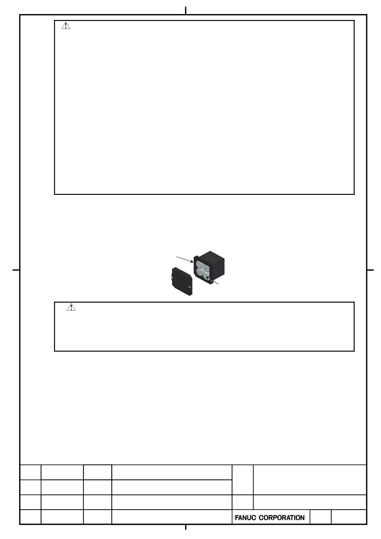
3.3.3
How to insert batteries into the battery case
Use the following procedure to replace the batteries in the battery case.
<1> Loosen the screws on the battery case and detach the cover.
<2> Replace the batteries in the case (pay attention to the polarity).
<3> Attach the cover to the battery case.
Battery case
A06B-6050-K060
Battery A06B-6050-K061
or four D-size alkaline dry cells
CAUTION
・ Four D-size alkaline dry cells (LR20) that are commercially available can be used as batteries.
A set of four A06B-6050-K061 batteries is optionally available from FANUC.
・ Replace all the four batteries with new ones. If old and new batteries are mixed,the absolute
position information in the absolute Pulsecoders may be lost.
3.3.4
How to replace the buit-in lithium battery
Use the following procedure to replace the lithium battery.
<1>
Remove the battery cover.
<2>
Install the lithium battery.
<3>
Install the battery cover.
α+ series SERVO AMPLIFIER
TITLE
for 30+-B Start-up and
Maintenance manual
B-65285EN/03-02/04
NO.
EDT.
DATE
DESIG.
DESCRIPTION
PAGE
66 / 79
CUATION
・ Since a battery is not a commercial item, please be sure to purchase it from Fanuc. Therefore,
Fanuc recommend preparation of the spare battery.
・ When using the built-in batteries, do not connect them to the BATL (B3) of connector
CXA2A/CXA2B. The output voltages from different SV batteries may be short-circuited, resulting
in the batteries becoming very hot.
・ If it is attached where a battery cable is stretched, loose connection etc. may occur.
・ When +6V of CX 5X and 0V short-circuit, it becomes the cause of generation of heat of the
battery, a burst, ignition, and the absolute position information disappearance in an absolute
pulse coder.
・ In case you insert a connector, please insert horizontally to the direction of the pin of the
connector.
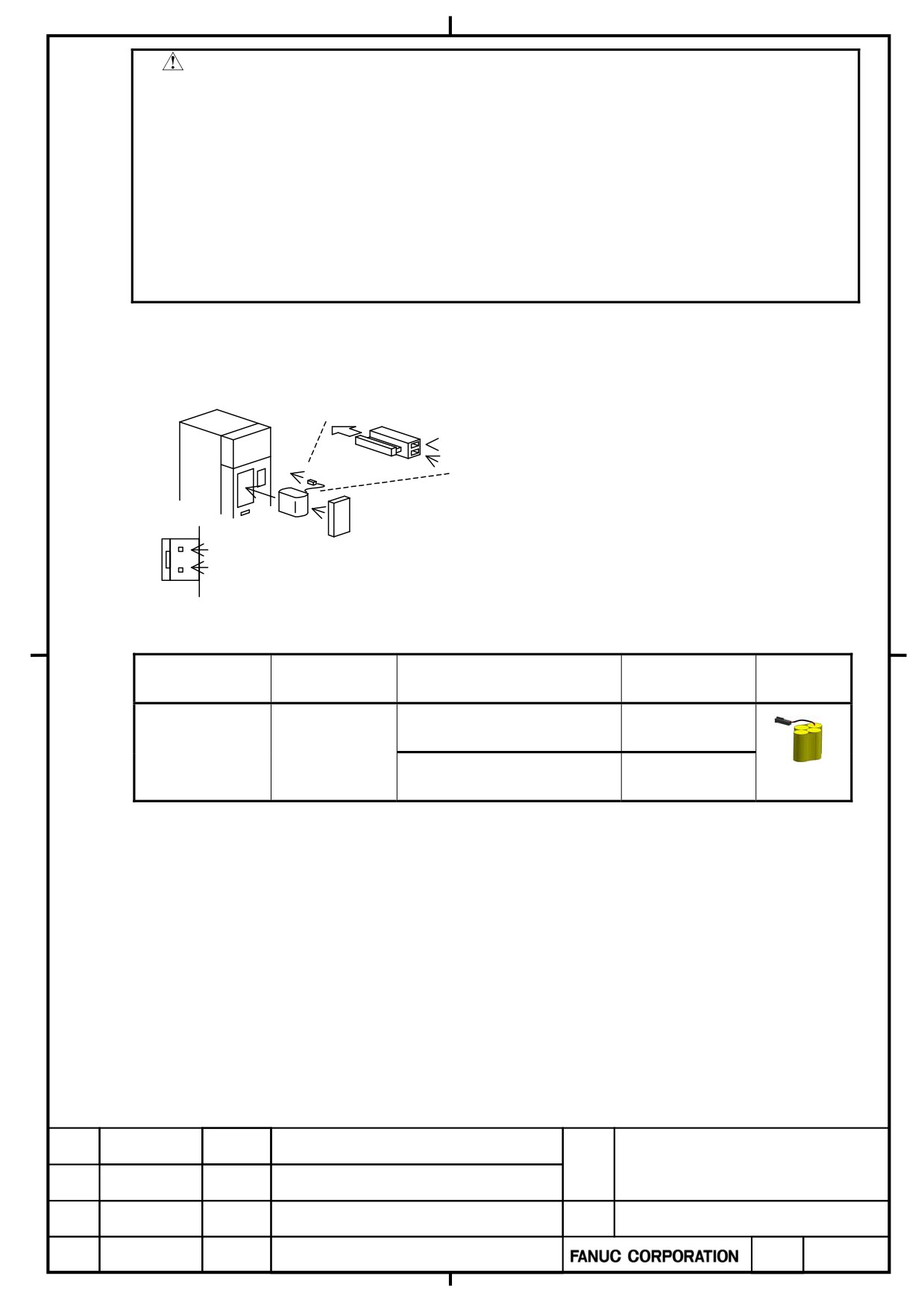
[Connection mathod of battery]
Τhe battery is installed in the front of servo
【αI series】
amplifier
Direction of insert
Cable side
Red:+6V
Connector
Black: 0V
CX5X
Battery
+6V
Battery case
0V
[Conbination and outlne of the battery]
Battery
Type
Battery case
Servo amplifier
Outline
Specification No.
Specification No.
BR-2/3AGCT4
A06B-6114-K50
α+series
60/90mm width
A06B-6114-K504
A
5
(note)
(Panasonic)
α+ series
150/300mm
A06B-6114-K50
width
6
(note)When old type battery BR-CCF2TH(A06B-6073-K001) is used, please order battery case battery case
A06B-6114-K500.
About a used battery
Please dispose correctly as "industrial waste" about the battery after exchange according to the law which the country in
which the machine was installed.
α+ series SERVO AMPLIFIER
TITLE
for 30+-B Start-up and
Maintenance manual
B-65285EN/03-02/04
NO.
EDT.
DATE
DESIG.
DESCRIPTION
PAGE
67 / 79
4. MAINTENANCE PARTS AND REPLACEMENT
METHODS
4.1.
HOW TO REPLACE FAN MOTORS
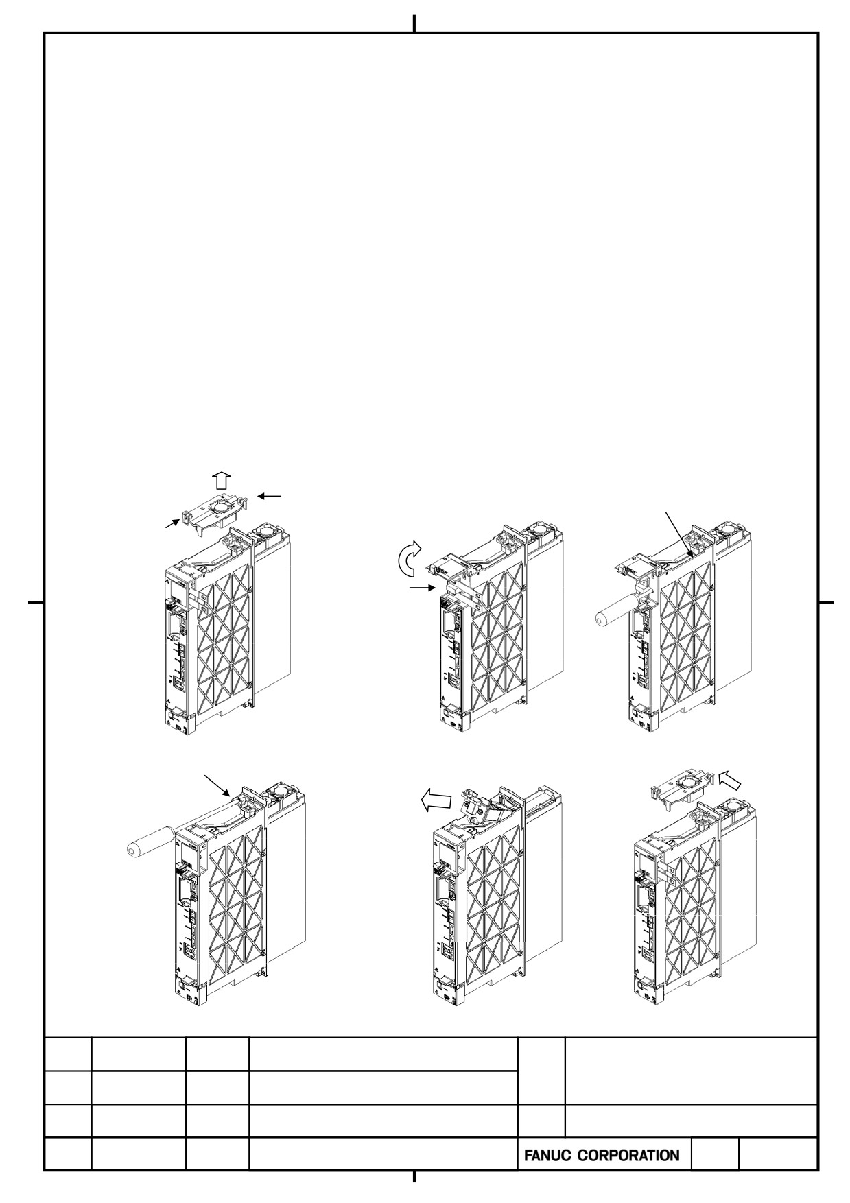
4.1.1
How to Detach Fan Units from 60 and 90 mm Width Units
(1) Holding the two lugs on the fan unit, lift the internal cooling fan unit upward.(Removal of internal cooling fan unit is
completed.)
(2) The lock of DC link terminal cover is released, and DC link terminal cover is opened. And discharge of DC link (LED
has gone out) is checked, and DC link short bar is removed.
(3) From the hole beside DC link terminal, the screw driver is inserted and the lower screw (one place) of the radiator
cooling fan unit is loosened.
(4) The upper screw (60mm wide is one place and 90mm wide is two places) of the radiator cooling fan unit is loosened.
(5) The radiator cooling fan unit is pulled out to the front.(Removal of radiator cooling fan unit is completed.)
(6) When it mounts, the fan unit is mounted in the reverse procedure.
Note) The connector may be hard to fit in at the time of mounting of the internal fan unit. In that case, please mount,
pushing the lug by the side of the back of the internal fan unit to the left.
(1)
(2)
(3)
Lug
Lower screw
Lug
Discharge
check
(4)
Upper screw
(5)
Note)
α+ series SERVO AMPLIFIER
TITLE
for 30+-B Start-up and
Maintenance manual
B-65285EN/03-02/04
NO.
EDT.
DATE
DESIG.
DESCRIPTION
PAGE
68 / 79
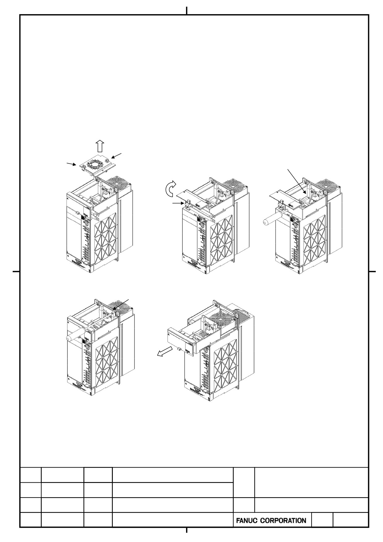
4.1.2
How to Detach Fan Units from 150 and 300 mm Width Units
(1) Holding the two lugs on the fan unit, lift the internal cooling fan unit upward.(Removal of internal cooling fan unit is
completed.)
(2) The lock of DC link terminal cover is released, and DC link terminal cover is opened. And discharge (LED has gone
out) of DC link is checked, and DC link short bar is removed.
(3) From the hole beside DC link terminal, the screw driver is inserted and the lower screw (one place) of the radiator
cooling fan unit is loosened.
(4) The upper screw (one place) of the radiator cooling fan unit is loosened.
(5) The radiator cooling fan unit is pulled out to the front.(Removal of radiator cooling fan unit is completed.)
(6) When it mounts, the fan unit is mounted in the reverse procedure.
(1)
(2)
(3)
Lug
Lug
Lower screw
Discharge
check
(4)
(5)
Upper screw
α+ series SERVO AMPLIFIER
TITLE
for 30+-B Start-up and
Maintenance manual
B-65285EN/03-02/04
NO.
EDT.
DATE
DESIG.
DESCRIPTION
PAGE
69 / 79
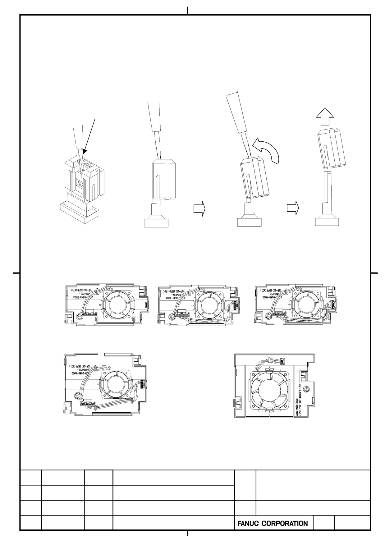
4.1.3
How to Detach Fan Motors from the Internal Cooling Fan Unit
(1) Remove the connector (one piece or two pieces) from the case. (Refer to the following figure for details.)
① Put the slotted screwdriver with a width less than 3mm in the gap between the case and the connector.
② Slant the slotted screwdriver in the direction of an arrow.
③ Pull the connector in the direction of an arrow.
①
②
③
Screwdriver
Slant
(2) Remove the fan motor from the case.
. The internal cooling fan unit for 60mm width amplifier
(There are three kinds of fan units distinguished with connector composition.)
The internal cooling fan unit for 90mm width amplifier
The internal cooling fan unit for 150mm width amplifier
Be careful of direction of a fan motor and a connector when exchanging fan motor. When
mounting a fan motor in amplifier, a fan motor's label turns to a top.
α+ series SERVO AMPLIFIER
TITLE
for 30+-B Start-up and
Maintenance manual
02
2011.10.12
4.1.3 paragraph is corrected
B-65285EN/03-02/04
NO.
EDT.
DATE
DESIG.
DESCRIPTION
PAGE
70 / 79
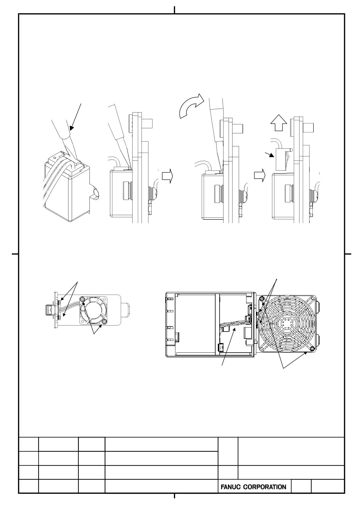
4.1.4
How to Detach Fan Motors from the Radiator Cooling Fan Unit
(1) In the case of the fan unit for 150mm width and 300mm width amplifier, remove the relay connector from the fan
motor's connector. (There is no relay connector in the fan unit for 60mm and 90mm width amplifier.)
① Put the slotted screwdriver in the gap between the case and the relay connector.
② Slant the slotted screwdriver in the direction of an arrow.
③ Pull the relay connector in the direction of an arrow.
①
②
③
Screwdriver
Slant
Relay
connector
(2) Remove two or four screws which are fixing the fan motor.
(3) Remove two screws which are fixing the fan motor's connector.
Screws for connector fixing
Screws for connector fixing
Screws for fan motor fixing
Relay Connector
Screws for fan motor fixing
α+ series SERVO AMPLIFIER
TITLE
for 30+-B Start-up and
Maintenance manual
02
2011.10.12
4.1.4 paragraph is corrected
B-65285EN/03-02/04
NO.
EDT.
DATE
DESIG.
DESCRIPTION
PAGE
71 / 79
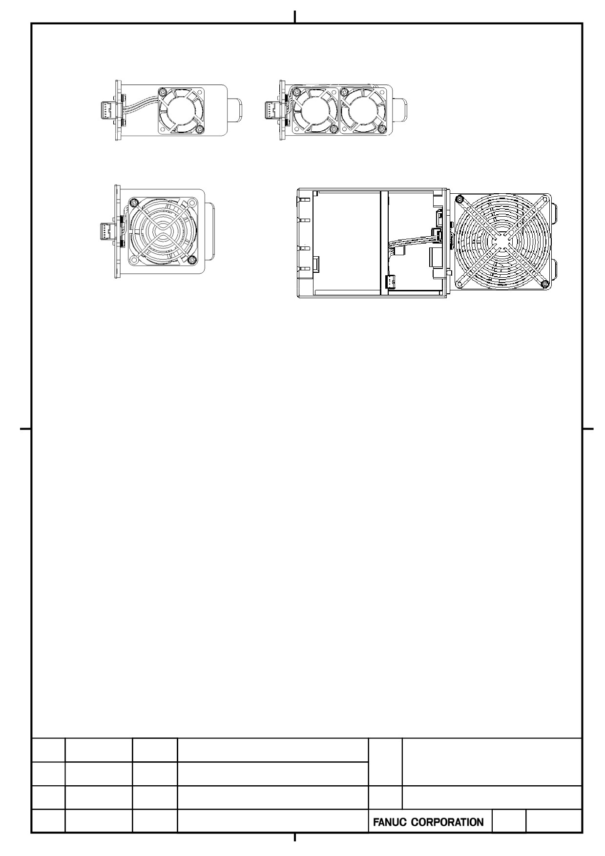
The radiator cooling fan unit for 60mm width amplifier
(There are two kinds of fan units distinguished by the number of fan motors.)
The radiator cooling fan unit for 90mm width amplifier
The radiator cooling fan unit for 150mm width amplifier
Be careful of direction of a fan motor and a connector when exchanging fan motor. When
mounting a fan motor in amplifier, a fan motor's label turns to a top.
α+ series SERVO AMPLIFIER
TITLE
for 30+-B Start-up and
Maintenance manual
02
2011.10.12
4.1.4 paragraph is corrected
B-65285EN/03-02/04
NO.
EDT.
DATE
DESIG.
DESCRIPTION
PAGE
72 / 79
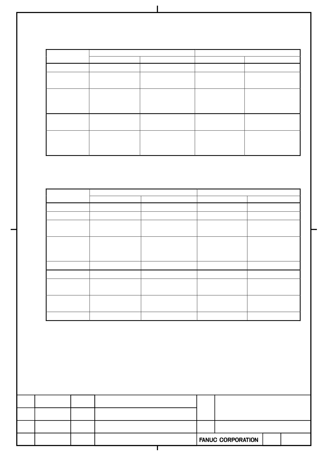
4.1.5
Specification of Fan Unit and Fan Motor for Maintenance
・Power Supply
Internal cooling fan
Radiator cooling fan
Model
Fan unit
Fan motor
Fan unit
Fan motor
α+PS 7.5
A06B-6200-C607
A90L-0001-0580#B
A06B-6200-C601
A90L-0001-0575#A
α+PS 11
A06B-6200-C609
A90L-0001-0580#B
A06B-6200-C603
A90L-0001-0576
α+PS 15
α+PS 26
α+PS 30
A06B-6200-C610
A90L-0001-0581
A06B-6200-C604
A90L-0001-0577
α+PS 37
α+PS 11HV
A06B-6200-C609
A90L-0001-0580#B
A06B-6200-C603
A90L-0001-0576
α+PS 18HV
α+PS 30HV
α+PS 45HV
A06B-6200-C610
A90L-0001-0581
A06B-6200-C604
A90L-0001-0577
α+PS 60HV
Basically, maintenance can be performed in the unit of the fan motor. The fan unit is the set of the cover for fan
motor attachment, and the fan motor. (Please refer to 「4.1. HOW TO REPLACE THE FAN MOTOR」.)
- Spindle Amplifier
Internal cooling fan
Radiator cooling fan
Model
Fan unit
Fan motor
Fan unit
Fan unit
α+SP 2.2
A06B-6200-C606
A90L-0001-0580#A
-
-
α+SP 5.5
A06B-6200-C607
A90L-0001-0580#B
A06B-6200-C601
A90L-0001-0575#A
α+SP 11
A06B-6200-C609
A90L-0001-0580#B
A06B-6200-C603
A90L-0001-0576
α+SP 15
α+SP 22
α+SP 26
A06B-6200-C610
A90L-0001-0581
A06B-6200-C604
A90L-0001-0577
α+SP 30
α+SP 37
A06B-6200-C610
A90L-0001-0581
A06B-6200-C605
A90L-0001-0578
α+SP 5.5HV
A06B-6200-C608
A90L-0001-0580#C
A06B-6200-C602
A90L-0001-0575#B
α+SP 11HV
A06B-6200-C609
A90L-0001-0580#B
A06B-6200-C603
A90L-0001-0576
α+SP 15HV
α+SP 22HV
A06B-6200-C610
A90L-0001-0581
A06B-6200-C604
A90L-0001-0577
α+SP 30HV
α+SP 45HV
A06B-6200-C610
A90L-0001-0581
A06B-6200-C605
A90L-0001-0578
Basically, maintenance can be performed in the unit of the fan motor. The fan unit is the set of the cover for fan
motor attachment, and the fan motor. (Please refer to 「4.2. HOW TO REPLACE THE FAN MOTOR」.)
α+ series SERVO AMPLIFIER
TITLE
for 30+-B Start-up and
Maintenance manual
02
2011.10.12
4.1.5 paragraph is corrected
B-65285EN/03-02/04
NO.
EDT.
DATE
DESIG.
DESCRIPTION
PAGE
73 / 79
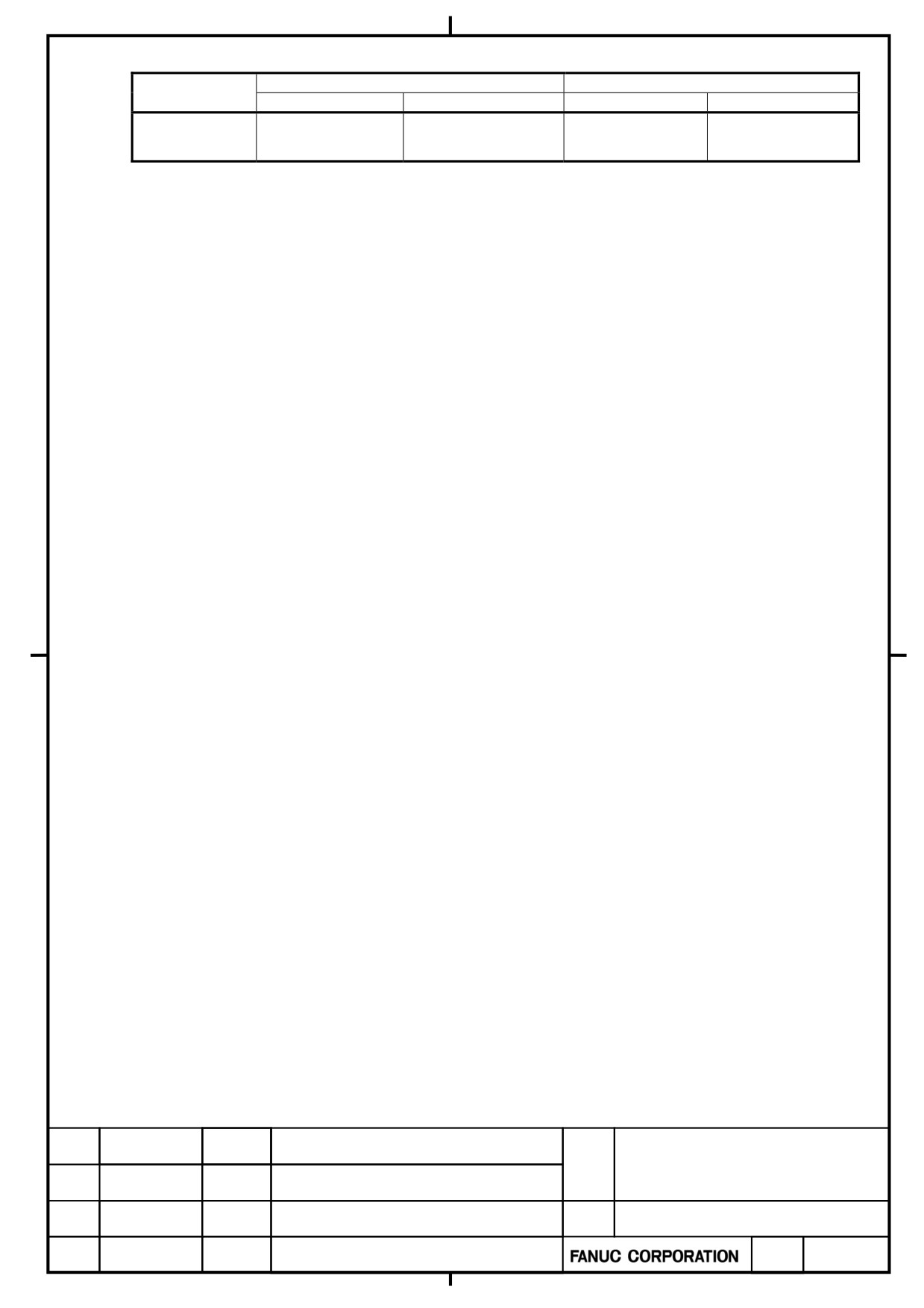
-Servo and Spindle Multi-axis Amplifier
Internal cooling fan
Radiator cooling fan
Model
Fan unit
Fan motor
Fan unit
Fan unit
α+SVP
A06B-6200-C609
A90L-0001-0580#B
A06B-6200-C603
A90L-0001-0576
20/20/20-5.5
Basically, maintenance can be performed in the unit of the fan motor. The fan unit is the set of the cover for fan
motor attachment, and the fan motor. (Please refer to 「4.2. HOW TO REPLACE THE FAN MOTOR」.)
α+ series SERVO AMPLIFIER
TITLE
for 30+-B Start-up and
Maintenance manual
02
2011.10.12
4.1.5 paragraph is corrected
B-65285EN/03-02/04
NO.
EDT.
DATE
DESIG.
DESCRIPTION
PAGE
74 / 79
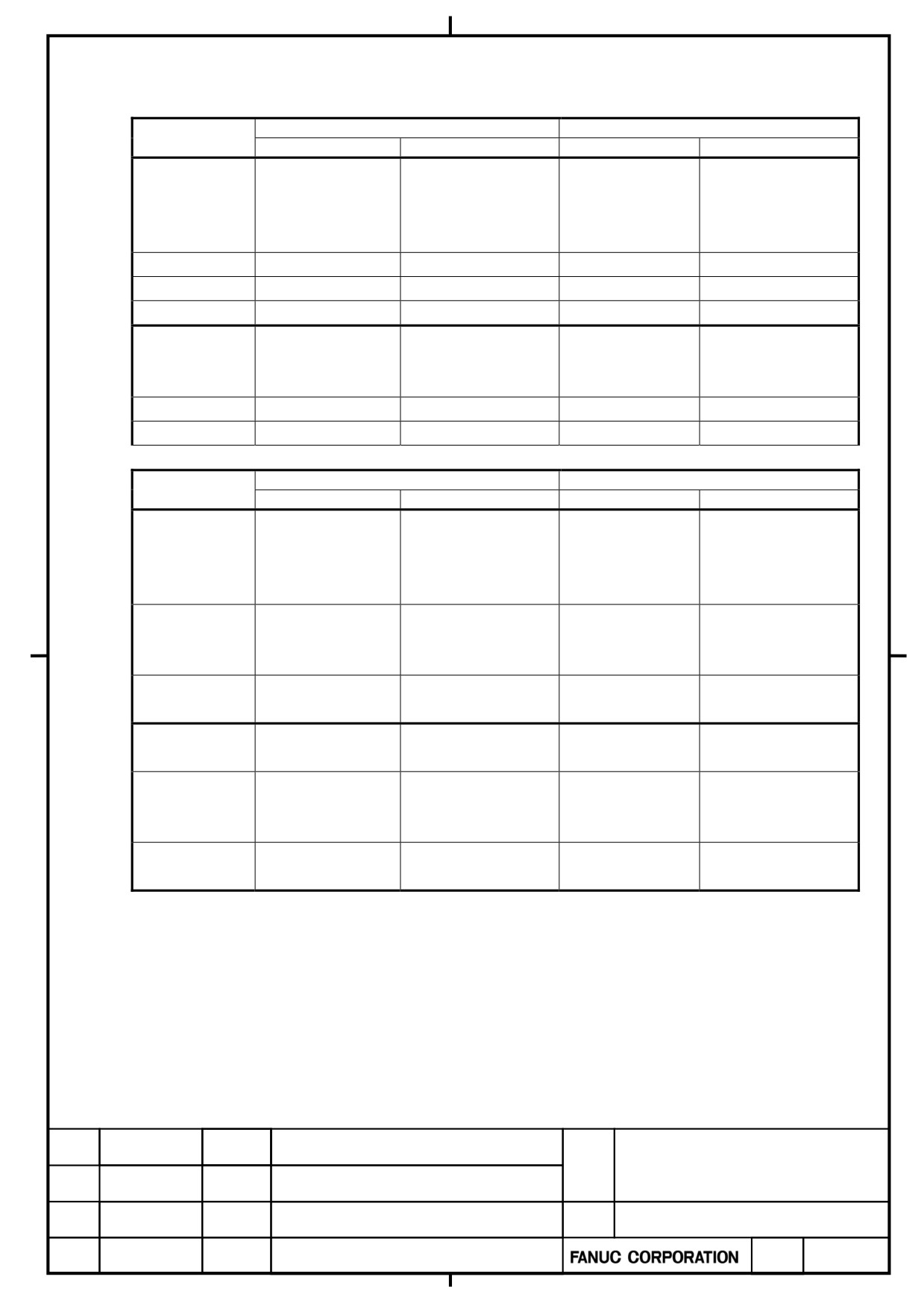
- Servo Amplifier Modules
(1) Single-axis servo amplifier (SVM1, 200VAC-input)
Internal cooling fan
Radiator cooling fan
Model
Fan unit
Fan motor
Fan unit
α+SV 4
α+SV 20
A06B-6200-C606
A90L-0001-0580#A
-
-
α+SV 40
α+SV 80
α+SV 160
A06B-6200-C608
A90L-0001-0580#C
A06B-6200-C602
A90L-0001-0575#B
α+SV 360
A06B-6200-C610
A90L-0001-0581
A06B-6200-C605
A90L-0001-0578
α+SV 160L
A06B-6200-C609
A90L-0001-0580#B
A06B-6200-C603
A90L-0001-0576
α+SV 10HV
α+SV 20HV
A06B-6200-C606
A90L-0001-0580#A
-
-
α+SV 40HV
α+SV 80HV
A06B-6200-C608
A90L-0001-0580#C
A06B-6200-C602
A90L-0001-0575#B
α+SV 180HV
A06B-6200-C610
A90L-0001-0581
A06B-6200-C605
A90L-0001-0578
(2) Two-axis servo amplifier (SVM2, 200VAC-input)
Internal cooling fan
Radiator cooling fan
Model
Fan unit
Fan motor
Fan unit
α+SV 4/4
α+SV 4/20
A06B-6200-C606
A90L-0001-0580#A
-
-
α+SV 20/20
α+SV 20/40
α+SV 40/40
α+SV 40/80
A06B-6200-C607
A90L-0001-0580#B
A06B-6200-C601
A90L-0001-0575#A
α+SV 80/80
α+SV 80/160
A06B-6200-C609
A90L-0001-0580#B
A06B-6200-C603
A90L-0001-0576
α+SV 160/160
α+SV 10/10HV
A06B-6200-C606
A90L-0001-0580#A
-
-
α+SV 10/20HV
α+SV 20/20HV
α+SV 20/40HV
A06B-6200-C607
A90L-0001-0580#B
A06B-6200-C601
A90L-0001-0575#A
α+SV 40/40HV
α+SV 40/80HV
A06B-6200-C609
A90L-0001-0580#B
A06B-6200-C603
A90L-0001-0576
α+SV 80/80HV
α+ series SERVO AMPLIFIER
TITLE
for 30+-B Start-up and
Maintenance manual
02
2011.10.12
4.1.5 paragraph is corrected
B-65285EN/03-02/04
NO.
EDT.
DATE
DESIG.
DESCRIPTION
PAGE
75 / 79
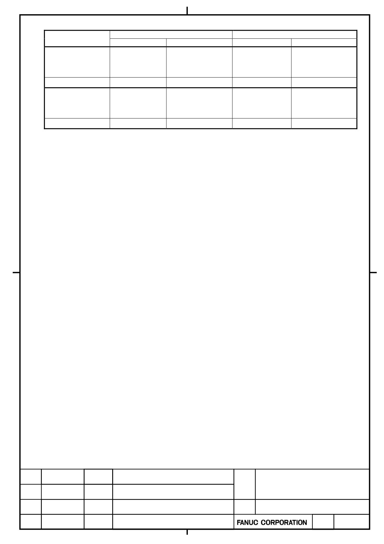
(3) Three-axis servo amplifier (SVM3, 200VAC-input)
Internal cooling fan
Radiator cooling fan
Model
Fan unit
Fan motor
Fan unit
α+SV 4/4/4
α+SV 20/20/20
A06B-6200-C606
A90L-0001-0580#A
-
-
α+SV 20/20/40
α+SV 40/40/40
A06B-6200-C608
A90L-0001-0580#C
A06B-6200-C602
A90L-0001-0575#B
α+SV 10/10/10HV
A06B-6200-C606
A90L-0001-0580#A
-
-
α+SV 10/10/20HV
α+SV 20/20/20HV
A06B-6200-C608
A90L-0001-0580#C
A06B-6200-C602
A90L-0001-0575#B
Basically, maintenance can be performed in the unit of the fan motor. The fan unit is the set of the cover for fan
motor attachment, and the fan motor. (Please refer to 「4.2. HOW TO REPLACE THE FAN MOTOR」.)
α+ series SERVO AMPLIFIER
TITLE
for 30+-B Start-up and
Maintenance manual
B-65285EN/03-02/04
NO.
EDT.
DATE
DESIG.
DESCRIPTION
PAGE
76 / 79
4.2.
HOW TO REPLACE FUSES ON PRINTED-CIRCUIT BOARDS
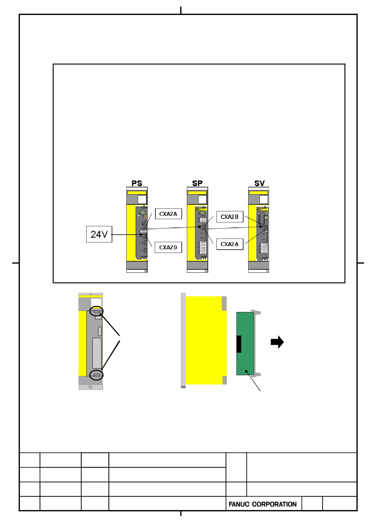
In theαi series, a printed-circuit board can be removed and inserted from the front of the servo amplifier.
The printed-circuit board removal/insertion procedure is common to the PS, SV, and SP.
Note
1. When the fuse is blowed, the cause by the power supply short circuit of other apparatus
(sensor etc.) connected to servo amplifier can be considered.
Please exchange the fuse after a check whether other apparatus is normal.
If the cause is not removed, there is a possibility that the fuse will be blowed again.
2. Please use the fuse supplied from FANUC.
3. Please check the rating mark on the PCB and seal of the fuse to prevent mistakes.
4. Reverse connection of 0V and 24V of the connector(CXA2D) for the external DC24V or the
connector(CXA2A/B) for the communication between amplifiers make the fuse blow.
[Countermeasure]
1.Replace the fuse.
2.Change to the correct connection.
Pull the PCB
toward front side
Hold the upper and
Lower hooks
PCB
To insert the printed-circuit board, reverse the above procedure.
Ensure that the upper and lower hooks snap into the housing.
If the printed-circuit board is not inserted completely, the housing
remains lifted. Pull out the printed-circuit board and insert it again.
α+ series SERVO AMPLIFIER
TITLE
for 30+-B Start-up and
Maintenance manual
03
2012.09.06
Yamada
Note 4 is added
B-65285EN/03-02/04
NO.
EDT.
DATE
DESIG.
DESCRIPTION
PAGE
77 / 79
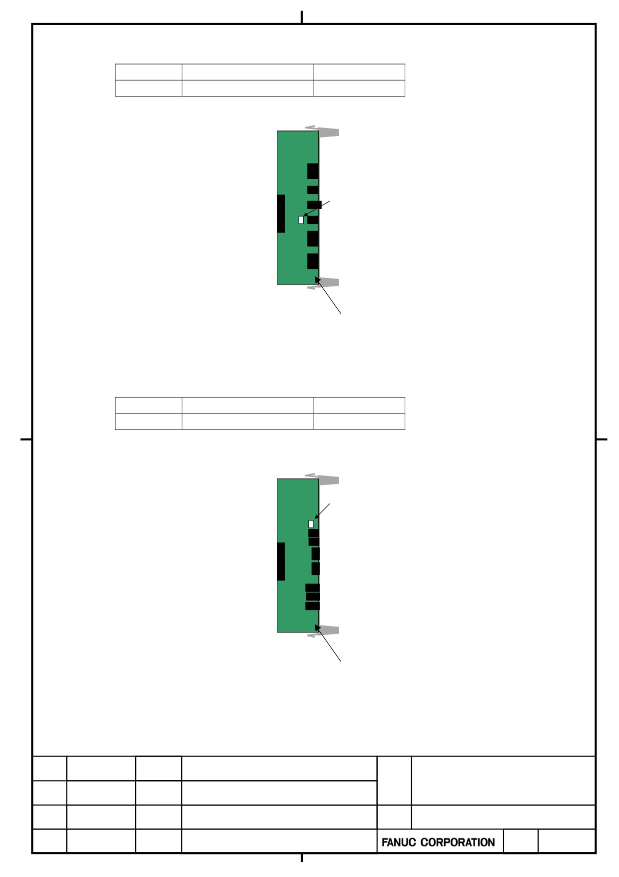
4.2.1
Power Supply
There is one fuse on the printed-circuit board for SP.
Symbol
Ordering number
Rating
FU1
A60L-0001-0290#LM32C
3.2A/48V
FU1(3.2A)
(Rating indicated in white)
Printed circuit board
4.2.2
Servo amplifier
There is one fuse on the printed-circuit board for SP.
Symbol
Ordering number
Rating
FU1
A60L-0001-0290#LM32C
3.2A/48V
(1)
60/90mm width servo amplifier
FU1(3.2A)
(Rating indicated in white)
Printed circuit board
α+ series SERVO AMPLIFIER
TITLE
for 30+-B Start-up and
Maintenance manual
B-65285EN/03-02/04
NO.
EDT.
DATE
DESIG.
DESCRIPTION
PAGE
78 / 79
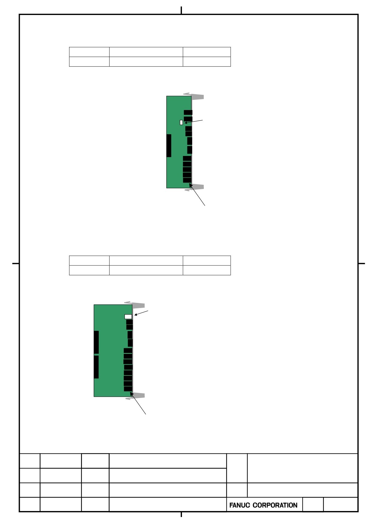
4.2.3
Spindle amplifier
There is one fuse on the printed-circuit board for SP.
Symbol
Ordering number
Rating
F1
A60L-0001-0290#LM32C
3.2A/48V
F1 (3.2A)
(Rating indicated in white)
Printed circuit board
4.2.4
Servo /Spindle multi-axis model
There is one fuse on the printed-circuit board for SVP.
Symbol
Ordering number
Rating
F1
A60L-0001-0290#LM32C
3.2A/48V
F1 (3.2A)
(Rating indicated in white)
Printed circuit board
α+ series SERVO AMPLIFIER
TITLE
for 30+-B Start-up and
Maintenance manual
B-65285EN/03-02/04
NO.
EDT.
DATE
DESIG.
DESCRIPTION
PAGE
79 / 79