Hyundai SKT 100/200 CNC TURNING CENTER. INSTALLATION MAINTENANCE MANUAL (VERSION No.: VOL1.0) - page 4
i.
Using the handle, confirm the distance from reference point to reduction signal OFF is
within the limits. If being out of the limits, readjust the dog.
j.
Perform para. 2 and 3 again and write the differences between "MACHINE" coordinate
value 380.000 (SKT100), 314.000 (SKT200) at axis parameter No. 1850 as the
running distance.
k. Turn off and then re-apply the power.
CAUTION
If para k has not been performed, it will not be operated properly.
5-10
V. REPAIR AND PRESERVATION
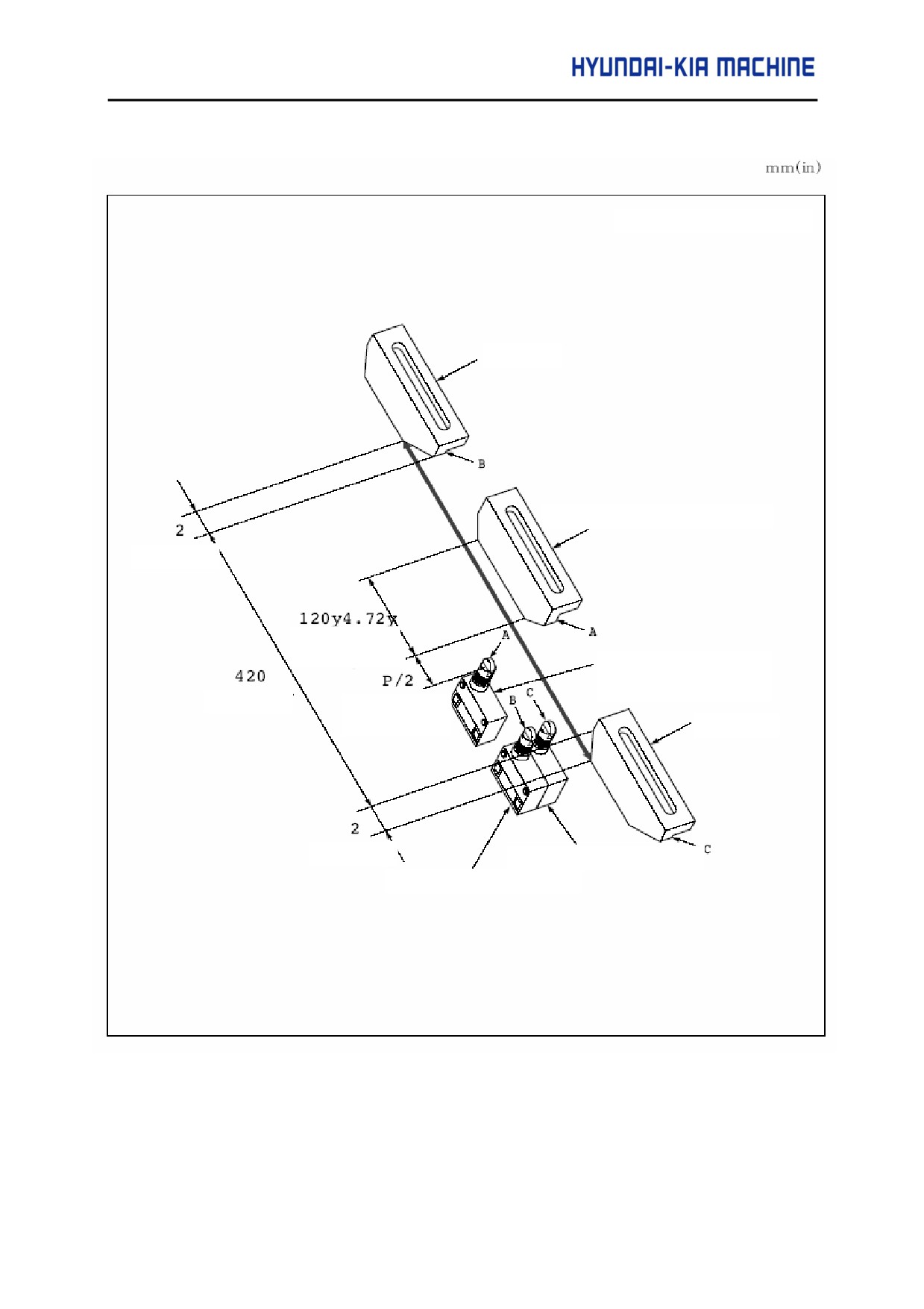
3) X-axis Dog and Limit Switch
P = 24grid (in diameter)
+OT Dog
Reference Point Dog
0.08
Reduction
range
Reference Point
Limit Switch
16.45
Reduction
OFF
+OT Dog
0.08
+OT Limit Switch
+OT Limit Switch
Fig. 5-5 X-axis Dog and Limit Switch Attached Position
5-11
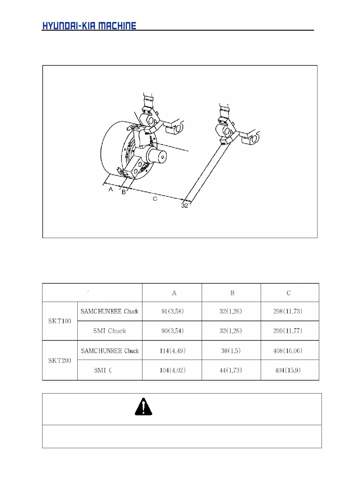
4) Z-axis
Standard Soft Jaw
Paper
Tab le 5-1. Chuck Dimensions
mm (in)
Type
Chuck
CAUTION
For SKT100/200, the reference point of Z-axis is different in diameter as shown in the above table, so
adjust it after checking the specification of Chuck.
5-12
V. REPAIR AND PRESERVATION
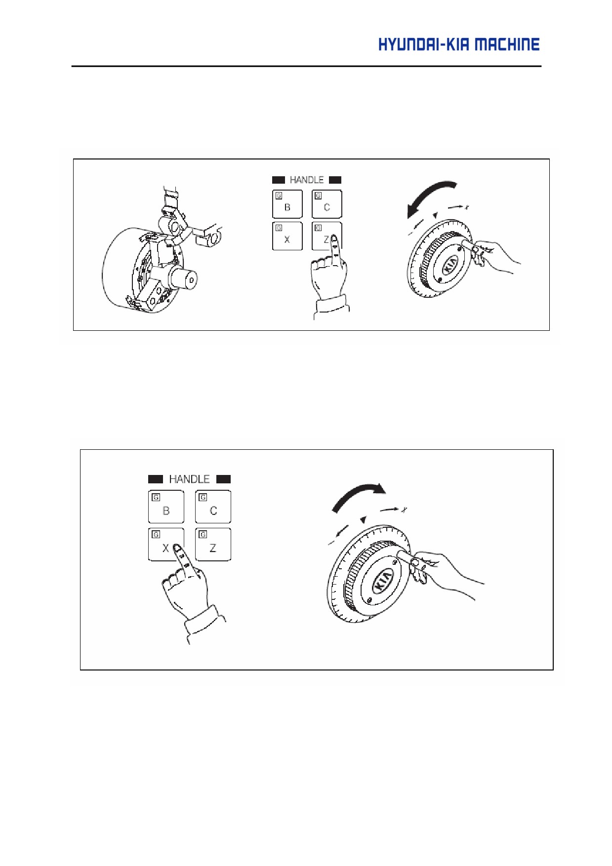
a. To approach the outer diameter bite tool to chuck and protect the blade end, use a thin
piece of paper, feed the handle and approach the tip end of bite tool to the jaw section
until the paper is not moved.
b. Set the "EXTERNAL" coordinate "Z" to "0" (see X-axis).
c. Set the mode to Handle X, move the head stock in the + direction of X-axis, and make
it not to be interfered with Tail Stock.
5-13
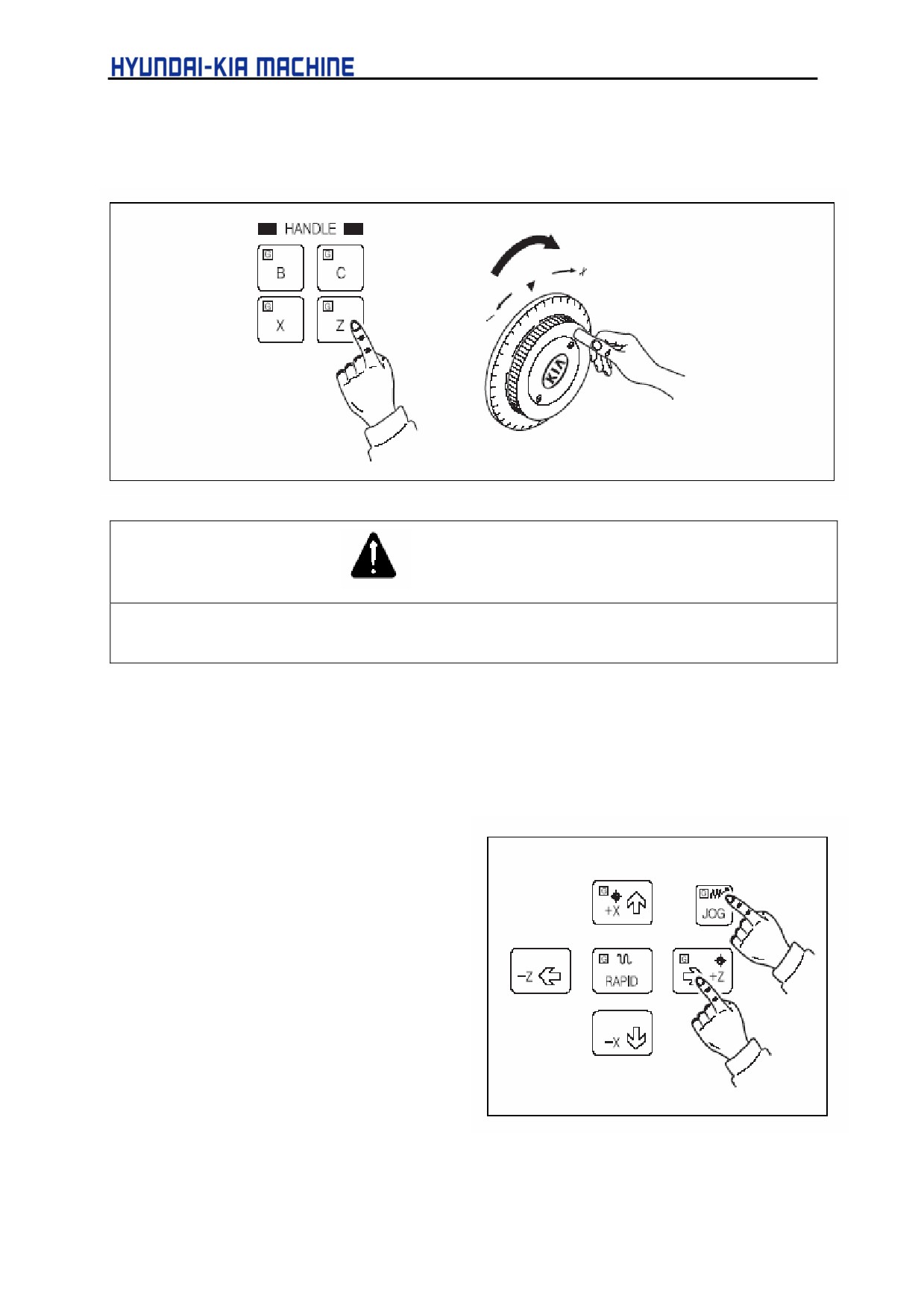
d. Using the handle, determine the position at reference point.
CAUTION
1.
Perform only in Z-axis.
2.
Position X-axis at a distance from reference point.
e. This time, move the current position to be "C" value of Table 5-1, set "EXTERNAL"
coordinate to "0" and then move it about 1/2 (6,000) of ball screw pitch in the opposite
direction to Reference Point Return.
f.
Move the reference point return dog to the position where reference point reduction signal
is turned ON.
g. Reference point return the Z-axis.
h. Using the handle, confirm the
distance from reference point to
reduction signal OFF is within the
specified range. If out of the
specified, readjust the dog.
i.
Perform para. 2 and 3 again and
write the differences between
"MACHINE" coordinate value and
"C" value of Table 5-1 at parameter
1850 as the grid shift amount.
j.
Turn off and then re-apply the
power.
5-14
V. REPAIR AND PRESERVATION
CAUTION
If the para. j being not performed, it will not be operated properly.
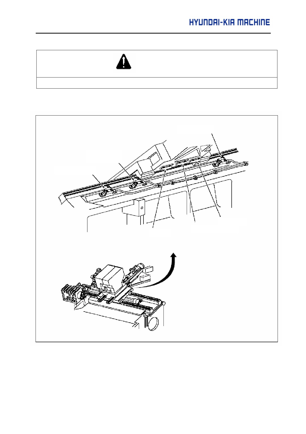
1-3-3. Z-axis Dog and Limit Switch Attached Position
-OT Limit Switch
Reference Point
Limit Switch
+OT Limit Switch
-OT Dog
Reference Point Dog
+OT Dog
Fig. 5-6 Z-axis Dog and Limit Switch Attached Position
5-15
1-4. X- and Z-axes Backlash Adjusting Method
1) Delete the compensation entered.
a. Select the setting screen and make the parameter change valid.
b. Select the parameter screen and delete the backlash compensation.
2) Measuring Backlash
a. Fit the dial indicator to the head stock from turret or Sub-spindle side.
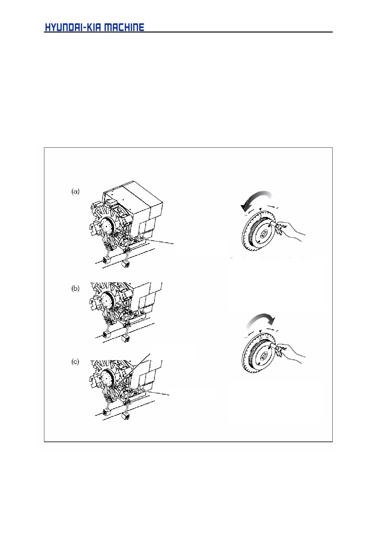
b. Measure the backlash using X- or Z-axis handle (See the following Fig.)
Dial indicator
0.002 mm
Turn the handle to the left and set
the Handle Indicator mode to "0".
Turn again the handle to the right of
20 ~ 30°.
Backlash in Z
Turn the handle to the right and
Backlash in X
set the pointer to "0". This time,
the difference of indicator
becomes the backlash.
5-16
V. REPAIR AND PRESERVATION
3) Setting Sequence of Backlash
a. Display the parameter screen as in above 1).
b. Confirm the cursor is positioned at no. of the axis to be compensated, key in the
compensated value and then press INSERT key.
Ex.
1) X-axis backlash compensation
If 0.012 of backlash is compensated,
Compensation =
Backlash Value
= 0.012
= 24 mm
Compensated Unit (0.0005)
0.0005
Ex.
2) Z-axis backlash compensation
If 0.015 of backlash is compensated,
Compensation =
Backlash Value
= 0.015
= 15 mm
Compensated Unit (0.001)
0.001
In the above method, input the specific backlash value.
c. Turn OFF and then re-apply the power.
CAUTION
If para. c being not performed, it is impossible to operate properly.
4) Checking Backlash
Check the setting value is proper in the method of 2).
5-17
1-5. Q-Setter Position Adjustment
After the machine collided or repaired, check the position of Q-setter is misaligned.
CAUTION
If the Q-setter used with misaligned, it requires the compensation as being misaligned.
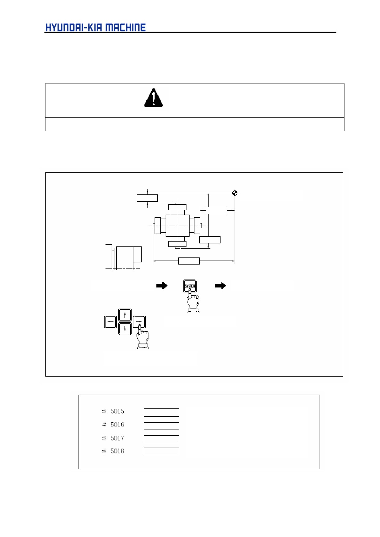
1) Check the distance parameter to the position of sensor.
Reference Point
#5016
#5018
#5015
#5017
Set #5016 “1”
Key in 5015
Press SYSTEM key
Press the Key, and "5015" will be
displayed.
For the inside of X-axis
For the outside of X-axis
For the opposite direction of Z-axis
For Z-axis
5-18
V. REPAIR AND PRESERVATION
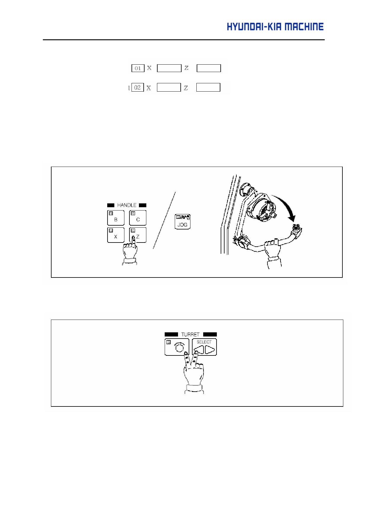
2) Check the offset of tool to be used in measuring.
1: Outside Tool
2: Inside Tool
3) Measure the compensation according to Q-setter.
a. Check the reference point return lamp is illuminated.
If not illuminated, perform the reference point return manually.
b. Set the mode to manual (JOG, handle feed) and pull out the Q-setter to the position to be
measured.
c. Call the tool to be used in measuring.
5-19
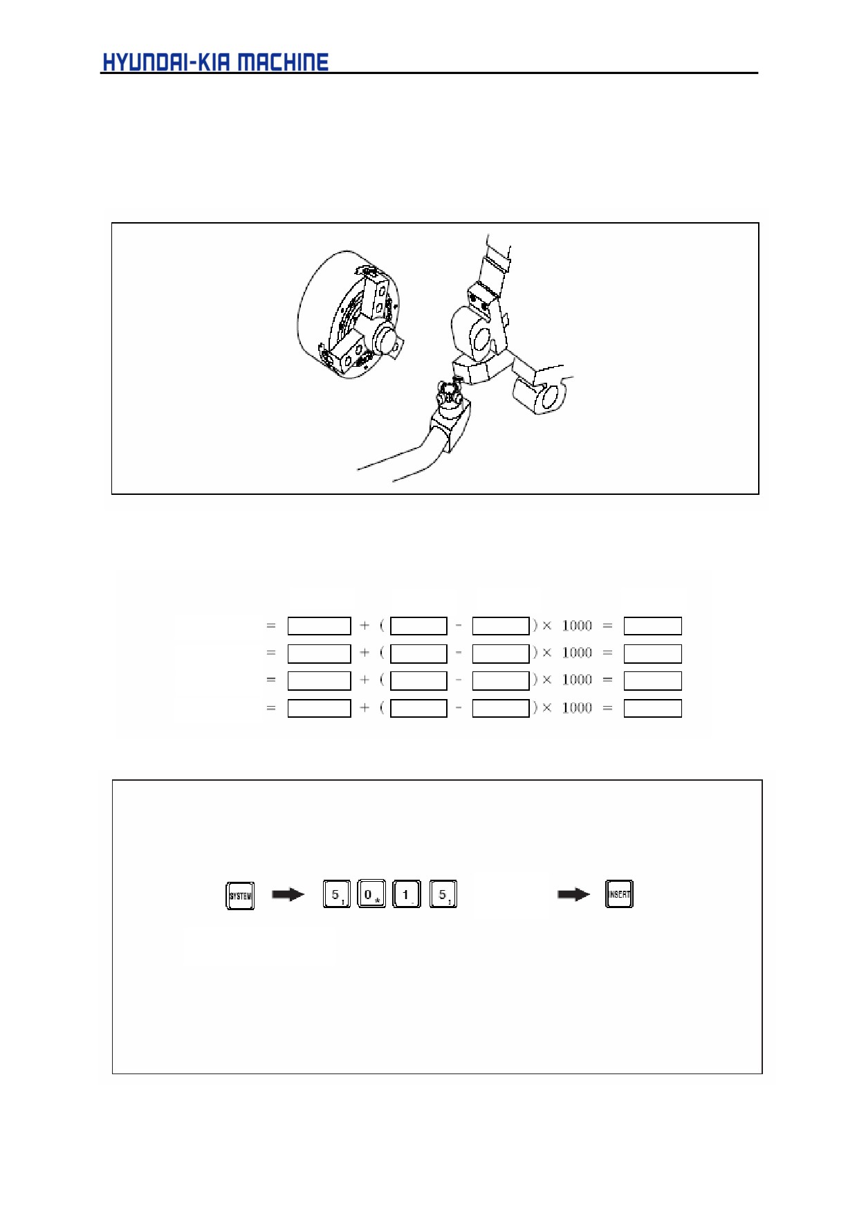
d. Approach the tool nose to Q-setter. If contacted to the sensor in the manual mode, the
tool offset will be input automatically.
4) Calculate new parameter to the position of center.
New parameter = old parameter + (new offset - old offset) x 1000
para. 1)
para. 3
para. 2)
para. 5)
new #5015)
new #5016)
new #5017)
new #5018)
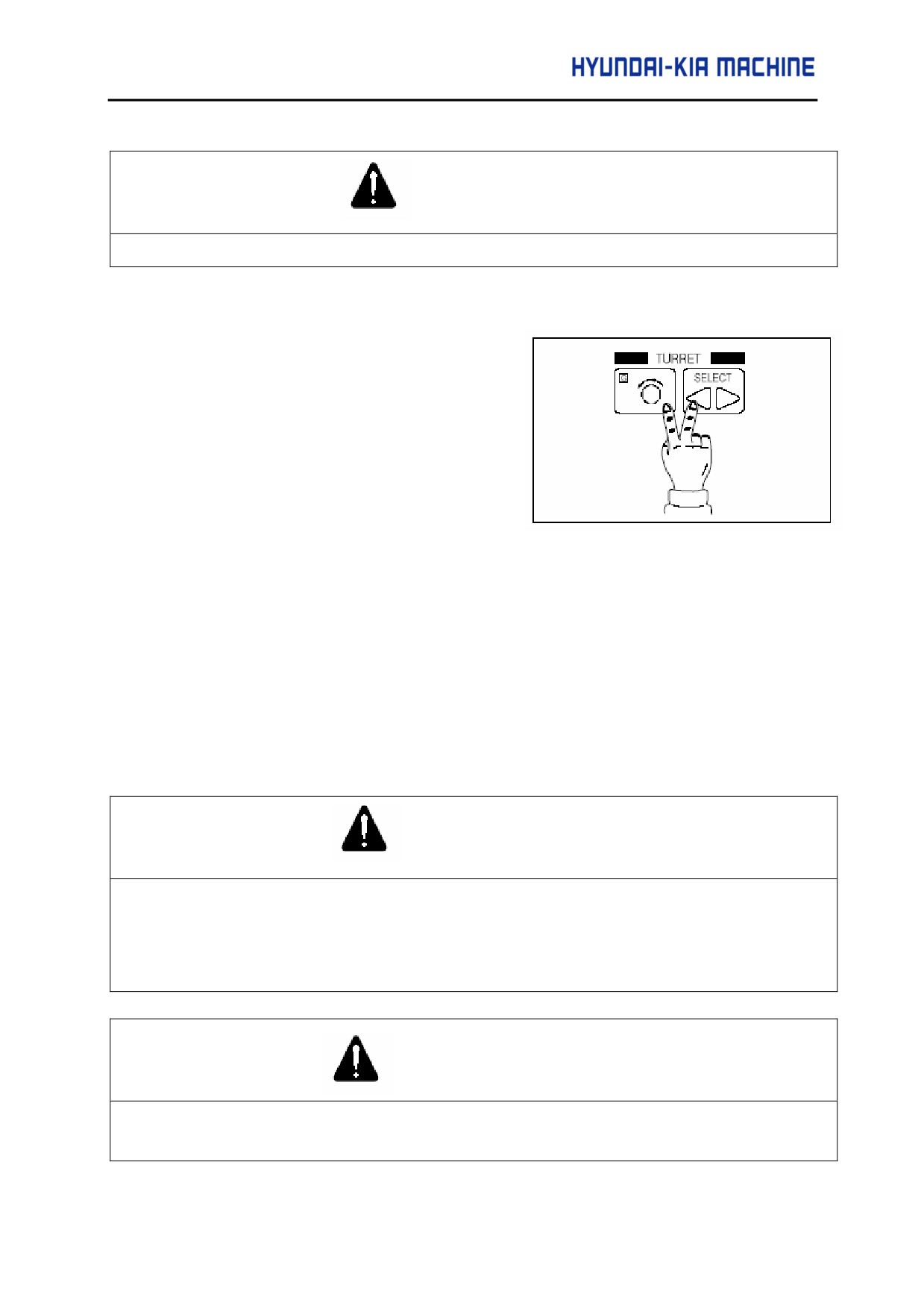
5) Set the parameter at #5015.
Key in the
data
Press [SYSTEM] Key
5-20
V. REPAIR AND PRESERVATION
CAUTION
After changing the data, always press the RESET key, turn off and then re-apply the power.
6) Adjusting Method according to Cutting. [(fine adjustment following data 5)]
a. Call the tool to be used in cutting.
b. When the desired value is assumed
at
50 mm by chucking the
workpiece, cut it with the work
coordinate set to 50.0.
c. Measure the workpiece has been
cut.
d. Calculate new parameter.
New parameter = (old parameter) + (measured value - desired value) x 1000
Ex. 1:
#5015 = (-60482) + (49.8-50.0) x 1000 = (-60482) + (-200) =-60682
Ex. 2:
#5015 = (-140657) + (50.25-50.0)x1000=(-140657)+250 = 140407
2.
General Check and Repair
2-1. General
1) General check and repair are essential to maintain the high integriy for a long time. So,
general check and repair take precedence of any other job.
CAUTION
1.
When doing the general check and repair, open the necessary cover or door and the door of electric
control panel remains closed.
2.
Never use compressed air. It may result in penetration of foreign matters into the spindle bearing
and guide-way.
WARNING
Prior to performing the general check and repair, place the main break of electric control panel to OFF as
shown in Fig. 5-7.
5-21
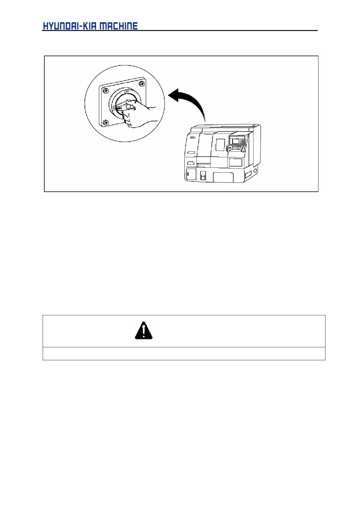
Fig. 5-7 Main Break Switch OFF Position
2) Always record the operation and check/repairing works.
Recording and Maintaining the operation is necessary for the operation of machine. Record
the check and repairing works independently from the operation.
3) Check and repair will be performed in short time. This short-term work is important to avoid
the unexpected accident or problem. And it is one of the important works to use the machine
effectively for a long time.
4) Oiling
WARNING
If the recommended oil didn't supplied, it may occur damage in the machine.
This machine has many places to be lubricated. When lubricating, "Avoid over-filling"
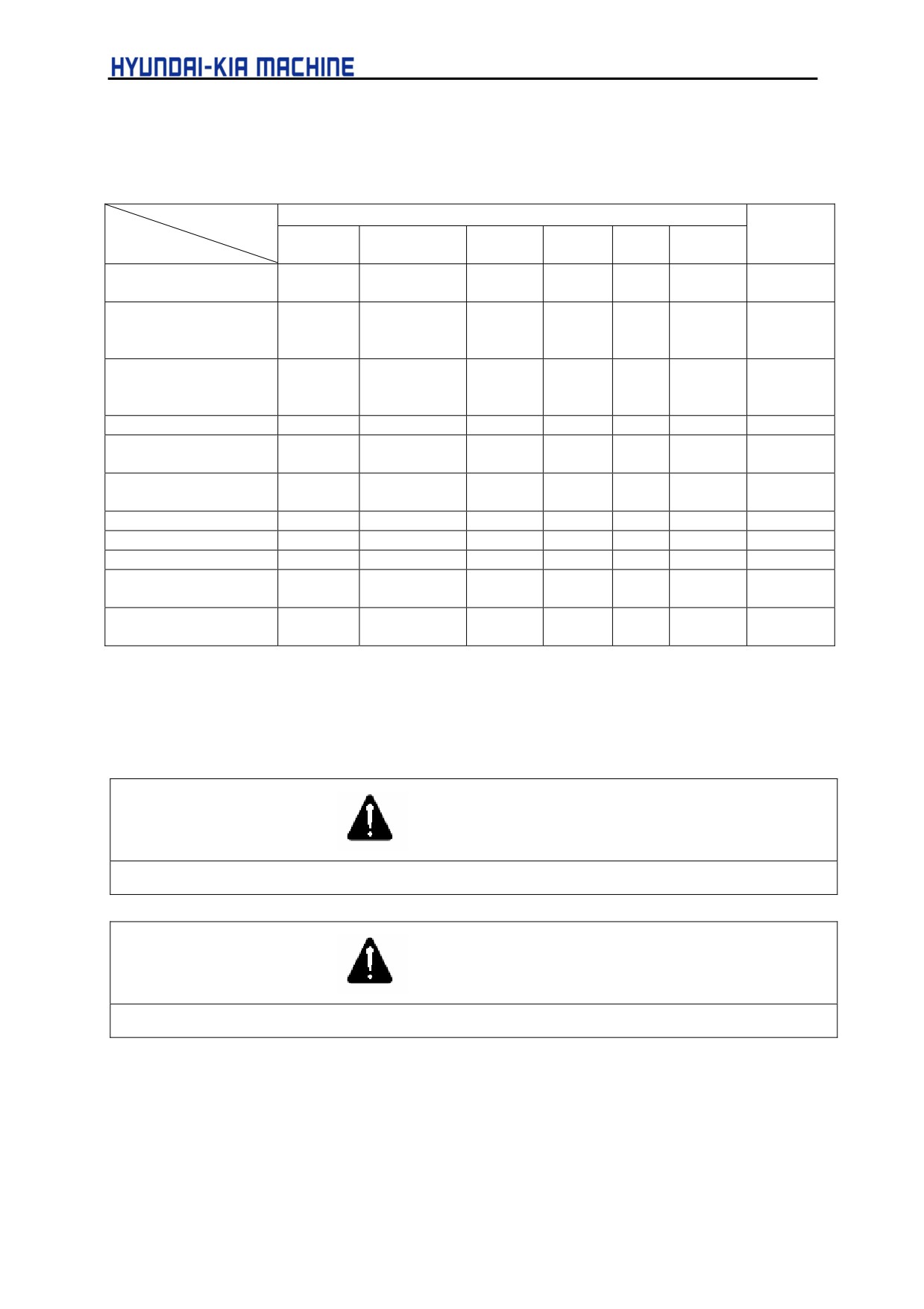
important. When oiling, follow this manual.
5) Check and repair can be performed daily, weekly, monthly and yearly. Check, fill oil an| clean
the machine as instructed in this manual.
5-22
V. REPAIR AND PRESERVATION
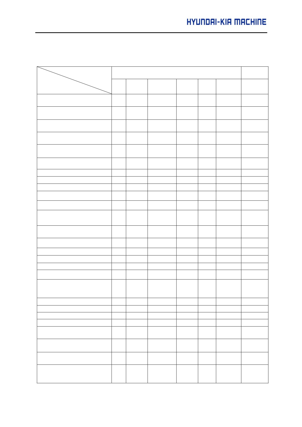
2-2. Check and Repair Items
Note:
{
Checking Period,
z CRT display
Checking and Repairing period
Reference
Period
Item
Daily
Weekly
Monthly
Six-
Yearly
Biennially
Reference
monthly
1. Remove chips inside the
{
2-3-1
machine
2. Remove chips above the
{
2-3-1
tool post
3. Remove chips above the tail
{
2-3-1
stock
4. Remove chips from each
{
2-3-1
slider cover
5. Clean coolant nozzle
{
3-6-3
(if clogged)
6. Treatment of chip
{
2-3-1
7. Clean coolant tank
{
3-6-2
8. Coolant filter
{
3-6-2
9. Check the hydraulic oil flow
{
2-3-3
10. Check the coolant flow
z
2-3-3
11. Check the lubricating flow
{
2-3-3
12. Hydraulic oil pressure 35
{
2-3-4
kgf/cm2
13. Check the lubricating oil
z
3-5-1
supply
14. Check the coolant supply
{
3-6-1
15. Hydraulic oil strainer
{
3-4-2
16. Lubricating pump filter
{
3-5-2
17. Clean around the machine
{
2-3-1
18. Oil leakage
{
2-3-3
19. Remove the tool chip and
{
2-4-2
check if damaged and
broken
20. Loosen bolt
{
21. Turret tool sank
{
2-4-2
22. Check Operating Panel
{
23. Clean the Electric Panel
{
24. Operation of emergency
{
stop switch
25. Vibration, noise and
{
increased temperature
26. Check the operation of
z
safety device
27. Check the tension of spindle
({ )
{
2-6-2
belt
one month after
installation
5-23
Check and Repair Items (Continued)
Note:
{
Checking Period,
z CRT display
Period
Checking and Repairing period
Reference
Item
Daily
Weekly
monthly
Six-
Yearly
Biennially
Monthly
28. Check the multi
{
2-6-2
cover of X-axis
29. Operation of the
{
2-6-2
wiper in X-and
Z-axes
30. Clean inside of the
{
3-6-2
coolant tank and
change oil
31. Moving hose
{
2-6-1
32. Clean the OSRAM
{
2-7-1
lamp
33. Relay in the
{
Electric Box
34. Machine level
{
35. Check backlash
{
1-4
36 Clean the fan
{
2-5-3
37. Clean the front
{
3-1-2
cover of spindle
38. Applying chuck
{
2-3-1
grease
2-3.
Daily Check and Repair
2-3-1. Inside of the Machine
DANGER
Before cleaning inside of the machine, always turn OFF the power.
CAUTION
Never use compressed air. It may result in the machine failure.
1) Use the tool such as brush, damp cloth, etc.
2) Remove chips and collect them in the chip box of machine.
5-24
V. REPAIR AND PRESERVATION
CAUTION
1.
First, pull the collected chips out of the machine and collect them into the chip box.
2.
Using coolant, clean the inside of machine.
3.
If chips not removed, it may cause a failure of the machine.
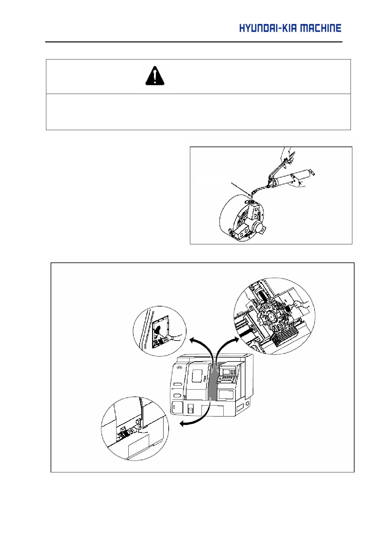
3) Inject the grease into the Chuck
and clean it. Use the specified
grease.
grease
Fig. 5-8 Checking the inside of Machine
5-25
2-3-2. Outside of the Machine
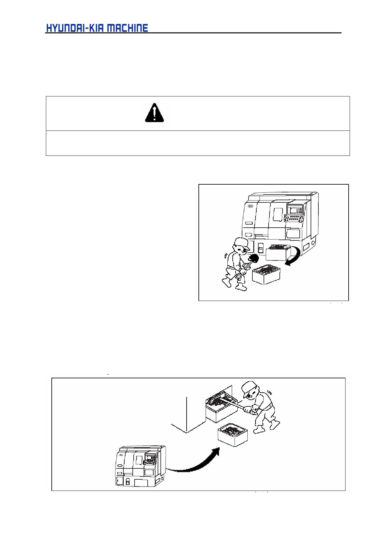
1) Remove the collected chips into the separated chip box.
WARNING
If there are coolant, grease or water on the floor, immediately wipe it out using damp clothes or papers.
Otherwise, it can cause personal injury from slipping.
Used tool: shovel, brush
A. If the machine hasn't equipped with
chip conveyor
a. Remove chips from the front of
the machine. Pull out the coolant
tank in front of the machine, pick
out chips from the chip box in
coolant tank and put them into a
separate container and return its
original position.
Fig. 5-9 Removing chips from the chip box(1/2)]
b. Remove chips from the rear of the machine
Disassemble the cover from a separate chip container, remove chips, put them int. the
chip box and then reassemble the cover.
Fig. 5-9 Removing chips from the chip box (2/2)
5-26
V. REPAIR AND PRESERVATION
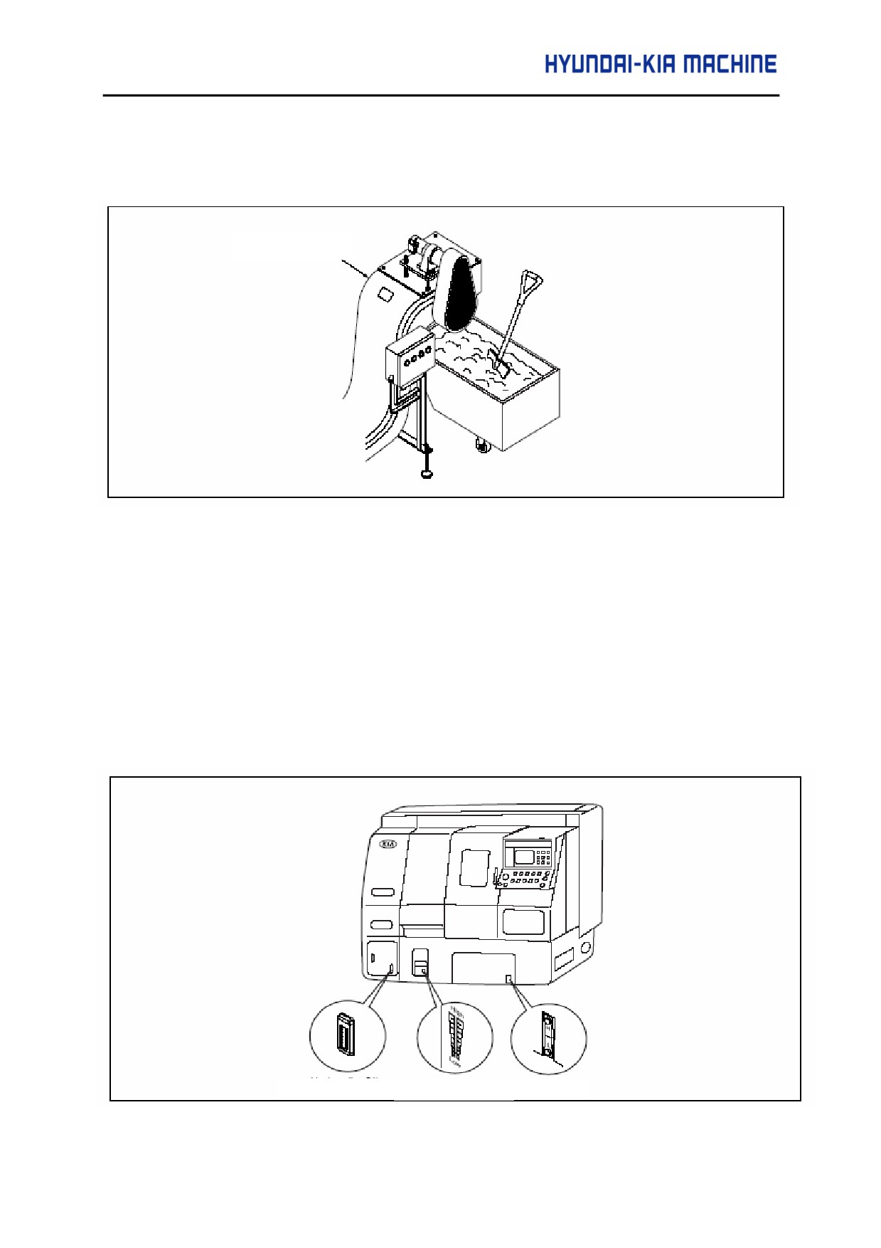
B. If the machine equipped with chip conveyor
Position the chip box just under the chip conveyor and remove the collected chips.
Chip conveyor
Fig. 5-10 Removing Chips out of the Chip Box
2-3-3. Checking Oil Flow
Oil flow can be checked by means of flow level gage in the tank. If filling oil, use the
recommended oil.
1) Check the flow of hydraulic oil
2) Check the flow of lubricating oil
3) Check the flow of coolant
Hydraulic oil
Lubricating
Coolant
Fig. 5-111 Checking Oil Flow
5-27
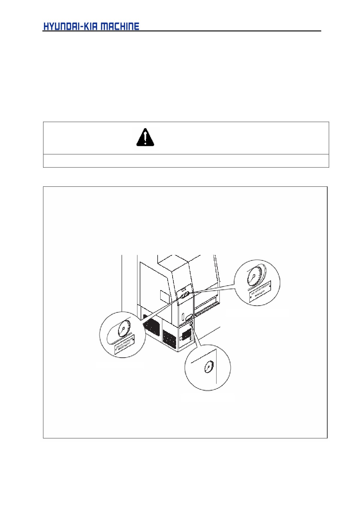
2-3-4. Checking Pressure
Check the pressures in Hydraulic unit, Chuck, Sub-chuck and Tail Stock.
1) Hydraulic unit: 35 kgf/cm2 (3.5 MPa)
2) Chuck: 5 ~ 27 kgf/cm2 (0.5 ~ 2.7 MPa)
3) Tail Stock: 1 ~ 20 kgf/cm2 (0.1 ~ 2 MPa)
WARNING
If being set above the specified pressure, it can cause machine failure.
Tail Stock pressure
Chuck Pressure
Hydraulic Unit Gage
Fig. 5-12 Checking Pressure
5-28
V. REPAIR AND PRESERVATION
2-3-5. Filling and Changing Oil
CAUTION
• If using soluble coolant
1.
Choose it in consideration of its characteristics such as rustproof, security, cooling, and etc.
2.
It should not include the contents dangerous to human body.
3.
It should not be deteriorated during the storage.
4.
It should not include corrosive or risk elements to the painting.
5.
It should not include elements melting to rubber products used in the machine.
6.
It should not include the contents which may degrade machine accuracy.
7.
Add a little rustproof oil when mixing coolant with soluble coolant. Otherwise, it may be rusted as
coolant dried.
8.
When completing work, wipe out the part contacted with coolant. Apply it with rustproof oil after
cleaning.
9.
Take care not to touch coolant with skin. Be sure you should be informed of its user's .instruction
for your health.
10. The mixing method of soluble coolant with water depends on the kinds of coolant and follow the
instructions of the manufacturer.
WARNING
Make sure the problem occurred by coolant, and etc. is not warranted.
1) Filling Oil (if necessary)
WARNING
If there is coolant, grease, or water on the floor, immediately wipe it out with damp clothes or papers.
Otherwise, it may cause personal injury.
5-29
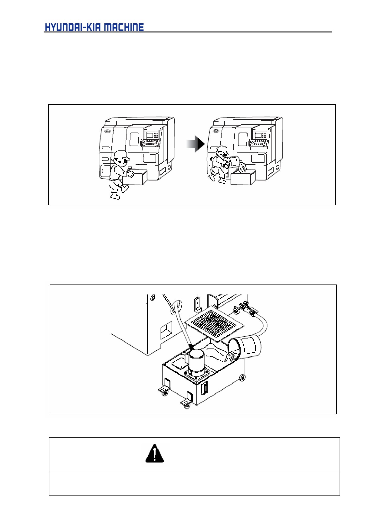
A. Filling coolant is possible in front or rear of the machine, but generally supplied at the rear.
a. Oiling in the front box of the machine
Pull out the coolant tank and fill it.
Fig. 5-13 Oiling in front of the machine
b. Oiling in the rear of machine
Disassemble the cover at the rear of machine, remove multi-hole iron plate from sub
tank, and then fill coolant.
Fig. 5-14 Oiling at the rear of machine.
WARNING
1.
Never touch coolant with bare hands.
2.
Coolant may damage the skin seriously:
5-30
V. REPAIR AND PRESERVATION
2-3-6. Around the Machine
1) Clean the outside of machine.
Wipe out oil and remove coolant, chip, and etc.
Clean CRT screen and operating panel with soft clothes dampened in cleaning solution.
2) Check there is an evidence of oil leakage outside of the machine.
3) Check if chips are removed, broken or damaged from the tool (insert),
2-4.
Weekly Check and Repair 2-4-1. Inside of the machine
2-4-1 Inside of the machine
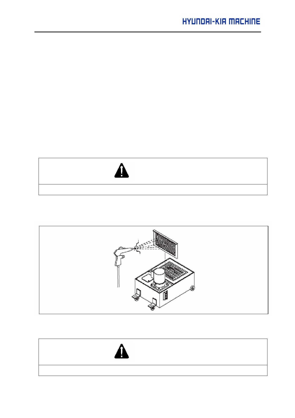
1) Cleaning the filter of coolant tank.
WARNING
When using compressed air, always wear protective goggles.
a. Use brush and air gun.
b. Remove the filter and clean it with brush.
Fig. 5-15 Cleaning the Filter of Coolant Tank
CAUTION
The use of air gun in the vicinity of the machine may cause the machine failure.
5-31
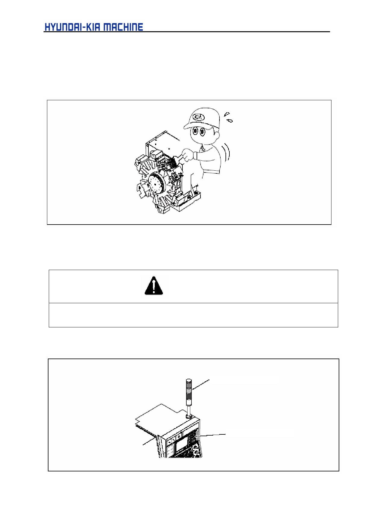
2-4-2. Outside of the Machine
1) Turret Tool Holder and Shank
Check the chips are removed from the tool holder or shank and engaging bolt is attached.
Fig. 5-16 Turret Tool Holder and Shank
2) Engaged State of Bolt
WARNING
1.
This check is for preventing a failure in advance.
2.
If neglecting this, it may cause the machine failure.
3) Check the Operating Panel is illuminated.
Petrol Lamp (Option)
Main Operating Panel
Fig. 5-17 Operating Position
5-32
V. REPAIR AND PRESERVATION
2-5.
Monthly Check and Repair
2-5-1. Inside of the Machine
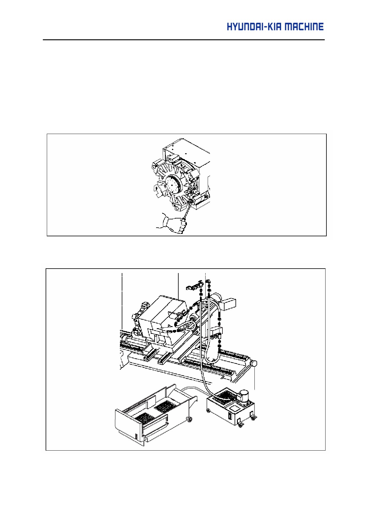
1) Cleaning the nozzle of coolant
Used tool: - and + screwdrivers
Remove chips around the coolant nozzle attached at turret.
Fig. 5-18 Removing Turret Nozzle Chip
Fig. 5-19 Coolant Supplying Route
5-33
2-5-2. Filling and Changing Oil
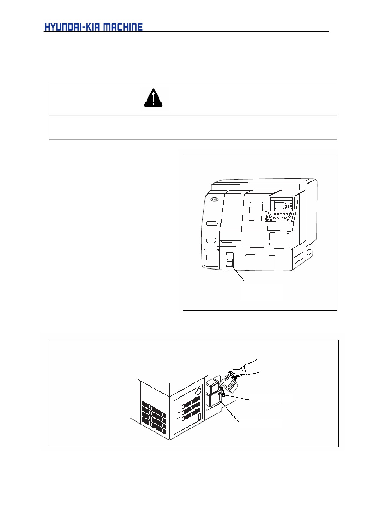
1) Filling lubrication Oil
WARNING
When filling lubricating oil, always use the recommended oil by KIA.
Otherwise, it may cause the machine failures.
a. tank capacity:
-1.8 l (0.47 gal)
b. Lubricating oil supply:
-33dd/h
Recommended oil:
See chap. 3-5-2 “Place to be
Lubricated”.
Lubricating Oil
Filling Position
Fig. 5-20 Lubricating Oil Filling Position
Oil Filter Plug
Oil Level Gage
Fig. 5-21 Filling Lubricating oil
5-34
V. REPAIR AND PRESERVATION
c. Open the plug of oil filter.
d. Fill the recommended lubricating oil up to the upper limit of level gage.
e. Plug the oil filter.
WARNING
When filling lubricating oil, wipe out dropped oil on the floor with damp clothes or papers. Otherwise, it
may cause personal injury.
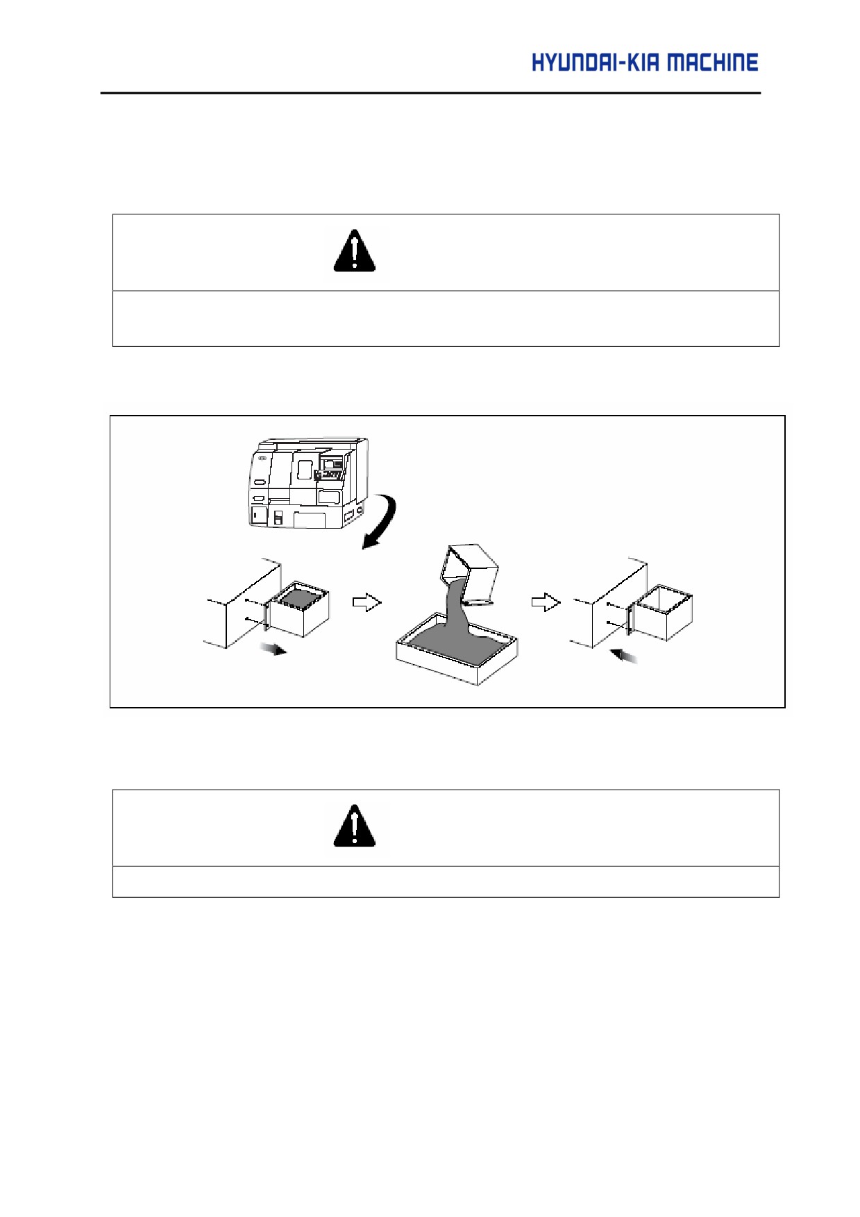
2) Whenever filling lubricating oil, always clean the waste oil tank.
Fig. 5-22 Cleaning Waste Oil Tank
WARNING
Unless the waste oil tank cleaned, it may cause personal injury due to overflow oil.
5-35
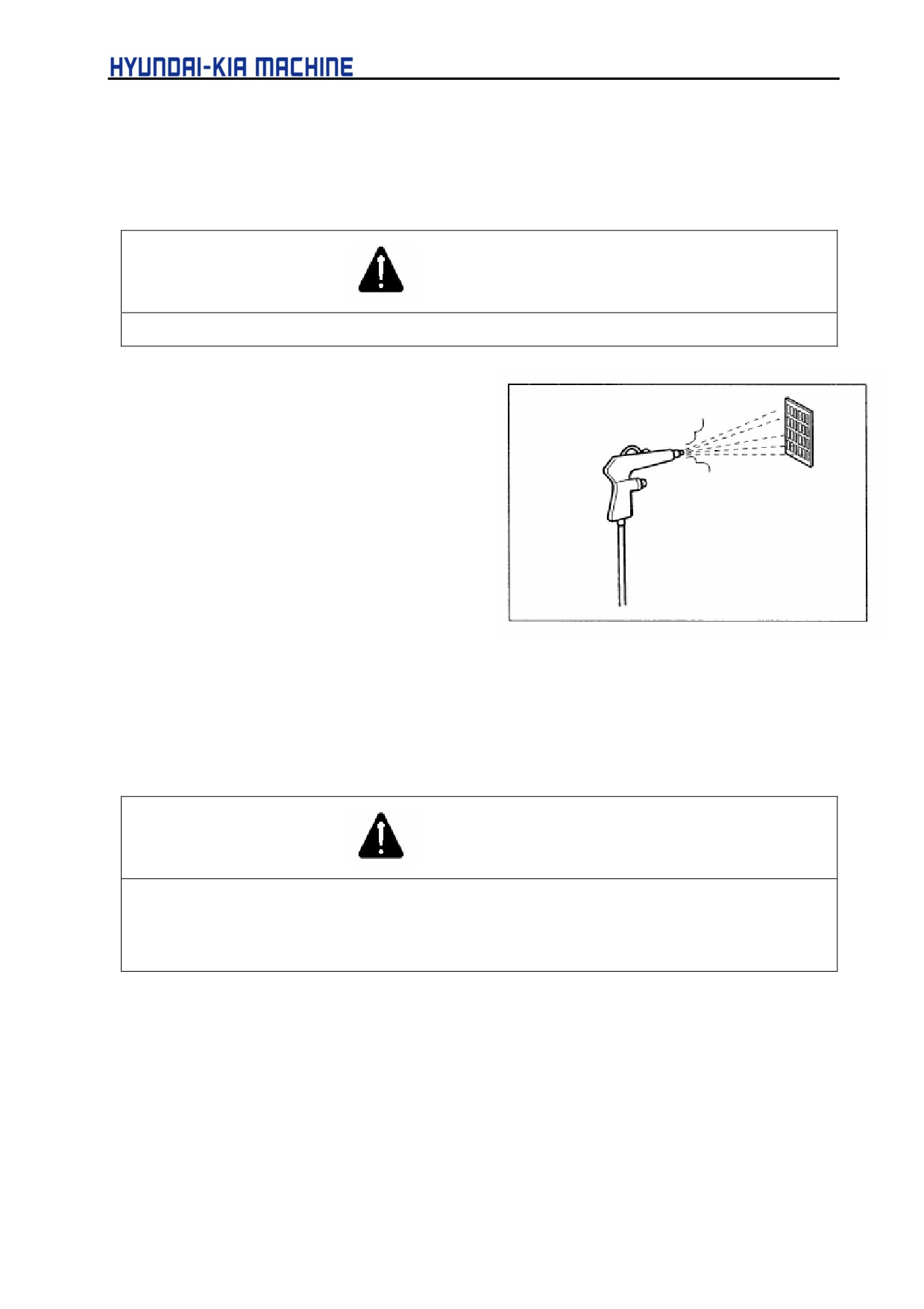
2-5-3. Outside of the Machine
1) Cleaning Cooling Fan
• Used tool: Wrench (3, 4, 5mm), damp clothes
WARNING
Before cleaning the fan, turn OFF the Main Power switch. Otherwise, it may cause personal injury.
a. Remove the door from the Electric
control panel and the fan filter from
the left side and then clean them
using air gun.
2-6.
Six-Monthly Check and Repair
2-6-1. Filling and Changing Oil
1) Exchanging Hydraulic Oil
WARNING
1.
Before exchanging the hydraulic oil, always turn OFF the power.
2.
When filling hydraulic oil, always use the recommended one by KIA.
Otherwise, it may cause the machine failures.
The hydraulic oil should be changed after the first 3 months of installation. Thereafter, change
it every 6 months.
Used tool:
Wrench (5 and 10 mm)
Oil capacity:
15 l (3.92 gal)
5-36
V. REPAIR AND PRESERVATION
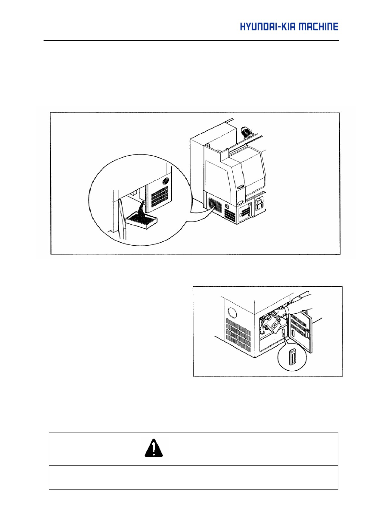
a. Turn OFF the main power switch in the electric control panel at the rear of machine.
b. Disassemble the bolt in the left lower cover and place the collection container under the
drain plug installed at the rear of hydraulic unit.
c. Loosen the drain plug and collect hydraulic oil.
Fig. 5-23 Collecting Oil of Hydraulic Unit
d. When completed, close the drain
plug.
e. Open the door for repairing in
front of the machine and the oil
filter cap and then supply the
hydraulic oil.
Fig. 5-24 Supplying Hydraulic Oil
2) Changing Coolant
Clean chips in coolant tank and perform in the following orders.
WARNING
When changing coolant, wipe out dropped oil on the floor with damp clothes or papers. Otherwise, it
may cause personal injury.
5-37
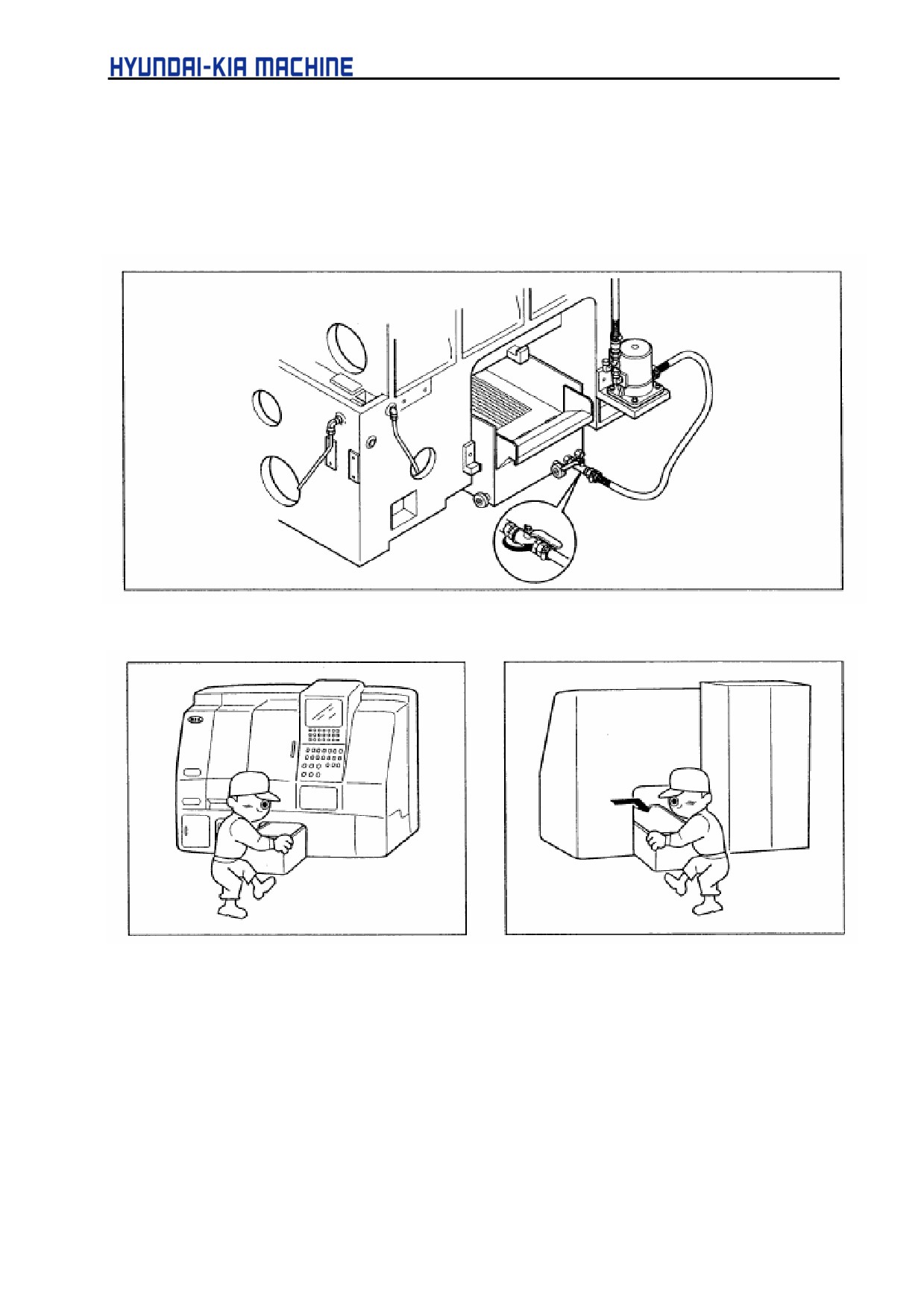
• Used tools: Coolant collecting box, damp clothes, shovel, wrench (17 mm),
+ screwdriver, coolant capacity 135 l (35.25 gal)
a. Lock the ball valve before disconnecting hoses between the main and sub tanks.
Fig. 5-25 Disconnecting Coolant Tank
Fig. 5-26 Main Tank
Fig. 5-27 Sub Tank
5-38
V. REPAIR AND PRESERVATION
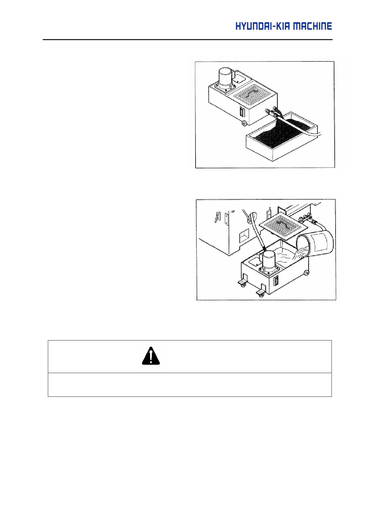
d. Position coolant collecting box
under the drain plug in main and
sub tanks, loosen the plug and
allow all coolant to drain.
Fig. 5-28 Collecting Coolant
e. Clean inside of the coolant tank
thoroughly.
f.
Clean the filter.
g. Slide coolant tank into the bed and
connect it with the main or sub tank.
h. Supply new coolant.
Fig. 5-29 Supplying Coolant
3) Checking Moving Hose
DANGER
Always turn OFF the power and then check moving hoses for damage.
Otherwise, it may cause personal injury.
5-39