Hyundai SKT 100/200 CNC TURNING CENTER. INSTALLATION MAINTENANCE MANUAL (VERSION No.: VOL1.0) - page 2
III. SPECIFICATION
2-1.
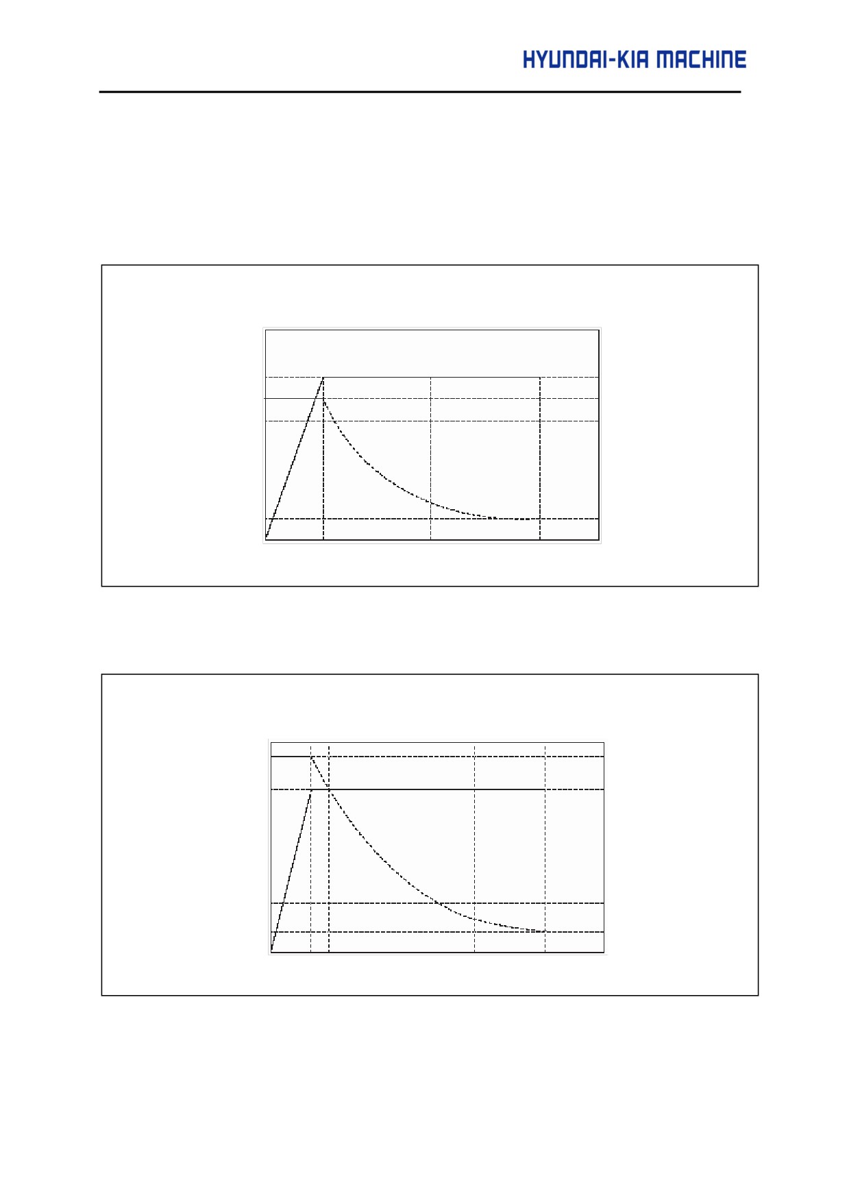
Spindle Output and Torque Diagram
• The constant output area and torque to ensure the rated output of machine are shown in
the followings.
• SUPER KIATURN 100
OUTPUT
6,000 ( rpm)
TORQUE
POWER
(kgfm)
(kW)
(Nm)
(HP)
7.5
10
6.33
62
5
6.7
5
49
1.22
12
1.154
3.000
6.000 (rpm)
Fig. 3-1 Output and Torque Diagram
• SUPER KIATURN 200
TORQUE
(kgfm)
OUTPUT
4,000 ( rpm)
(Nm)
POWER
13.36
(kW)
131
(HP)
11
14.6
5
5
49
6.7
2.68
26.3
802
1.000
3.000
4.000 (rpm)
Fig. 3-2 Output and Torque Diagram
3-3

3.
NC Device Specification (FANUC Oi-TA)
<Standard Specification>
Controlling Axis
X, Z-axis, simultaneous 2-axis.
Interpolation Function
Positioning straight line and arc interpolation.
Command Method
Absolute/Incremental.
Least Input Increment
0,001 mm, 0.001 deg
Tape Code
EIARS244/ISO 840 auto-identification.
M, S, T Function
Preparation G2, 3 digits, Aux. M2 digits, Tool T4 digits
Spindle Speed Command
S code rpm direct command.
Feed Command
F code feed rate direct command.
Feed Rate Override
0 ~ 200% (10% interval)
Rapid Feed Override
1%, 5%, 25/50%, 100%
Manual Feed Function
Rapid feed, Jog feed (0 ~ 2000 mm/min), Handle feed.
Manual Pulse Generator
Multiply x1, x10, x100 three stage exchange
Tool Position Offset
No. of offset : 32
Character Display
9 inch 512 characters (16 x 32)
Tape Memory Edit
320 m
Position Coder
6.000 rpm
Canned Cycle
G90, G92, G94
Thread Cutting Function G32
Constant Surface Speed Control
G96 S x x x x
Return to Reference
Manual, Auto G27-~ G30
Run Hour display
NC display
Nose R Compensation
Auto calculation (G40 ~ G42)
Spindle Max. Speed Setting
G50 Sx x x x
Auto Coordinate Setting
T code coordinate setting
Workpiece Coordinate Shift
Direct, increase/Decrease measured value G54 (workpiece
length)
Manual Absolute
"ON" Fix
Stored Stroke limit
1, 2, 3, G22, G23
Incremental Offset
U, W
3-4

III. SPECIFICATION
Offset Data Tape Reading
G10
Variable-lead Thread Cutting
G34
Program Checking
Dry run + Spindle Stop + Coolant Stop
Input/Output Interface
RS232 * 1
Block Skip
1EA
Arc. Radius R Designation
Chamfering R
Memory Lock Key
Skip Function
G31
Number of registerable Program
200EA
Single Block
Feed Hold
Optional Stop
Dwell
Decimal Point Input
Program No. Search
Sequence No. Search
Label Skip
Machine Lock
Dry Run
Backlash Compensation
0 ~ 255 pulse
NC Self Diagnostic Function
Inch/Metric Conversion
G20, G21
Canned Cycle for Drilling
G80, G83, G84, G85, G87, G88,
G79
Tool Life Management
Stored Pitch Error Compensation
Custom Macro B
Review spec, when using DI/DO
Background editing
*1. Only interface exists. The cable connected with I/O device is not included.
3-5

<Option Specification>
Temporarily Stop of Thread
(G92, G76)
Cutting
Multiple Start Thread Cutting
G76
Manual Absolute
Switch exchange type
Program Restart
Review spec. when using DI/DO
Optional Block Skip Addition
Review machine spec.
External Tool Offset
Review machine spec.
External Workpiece No. Search
Review machine spec.
External data Input
Review machine spec.
Auxiliary Function Lock
Return to the Set Up Point
Manual Interruption Point
Manual Interruption Point
Return
Angle Programming for Linear
Interpolation
Multiple Cornering
(Beveling & Rounding)
Skip Function
G31
Internal Toggle Switch
Spindle Index Function
Review machine spec.
Buffering Function
Graphic Function
3-6

III. SPECIFICATION
3-1. G-Function
B. Standard, O: Option
Standard
Group
Function
Type
G Code
G00
Positioning (rapid traverse)
B
G01
Linear interpolation, (Cutting feed)
B,O
01
G02
Circular interpolation CW
B
G03
Circular interpolation CCW
B
G04
Dwell
B
GO6
Error detecting OFF positioning
B
G10
Tool offset setting
B
G20
05
Inch input
O
G21
Metric input
O
G22
01
Circular interpolation radius R setting CW
O
G23
Circular interpolation radius R setting CCW
O
G27
Reference point return check
B
G28
Auto reference point return
B
G29
Return from reference point
B
G30
2nd reference point return
B
G31
Skip function
O
G32
01
Thread cutting, continuous thread cutting, multi thread cutting
B,O
(Option)
G34
Variable lead thread cutting
O
G35
Tool set error compensation
O
G36
07
The 2nd Stored stroke limit ON
B
G37
The 2nd Stored stroke limit OFF
B
G38
08
The 3rd Stored stroke limit ON
B
G39
The 3rd Stored stroke limit OFF
B
G50
Coordinate system setting
B
Max. spindle speed setting, work coordinate system setting.
O
G51
Return of current display value to origin
O
*
G65
Macro simple call
O
G66
09
Macro modal call
O
G67
Macro modal call cancel
O
G68
10
Programmable mirror image ON
O
G69
Programmable mirror image OFF
O
3-7

B:Standard, O: Option
Standard
Group
Function
Type
G Code
G70
Finishing cycle
Multiple repetitive
O
cycle
G71
Rough turning
O
G72
Rough facing
O
G73
Pattern repeating cycle
O
G74
End face peck drilling cycle
O
G75
Grooving in X-axis
O
G76
Thread cutting cycle
O
G90
01
Turning cycle A
B
G92
Thread cutting cycle
B
G94
Facing cycle B
B
G96
02
Constant surface speed control
B
G97
Constant surface speed control cancel
B
G98
04
Feed per minute (mm/min)
B
G99
Feed per revolution (mm/rev)
B
G122
11
Tool registration start
Tool Life Management
O
G123
Tool registration finish
O
G111
Taper multi chamfering/R
O
G112
Circular multi chamfering/R
O
G141
Tool nose R left compensation
B
G142
Tool nose R right compensation
B
G150
13
Groove width compensation OFF
B
G151
Groove width compensation ON
B
The G code of group 01-03 is called "modal G code" .
If the G code commanded, it is effective until another G code is done.
Group 01 : Controlling the movement of tool
Group 02 : Controlling the movement of tool
Group 04 : Controlling the movement of tool nose
Group 07 and 08 : Setting enable / disable area of tool
Group 01 : Controlling the groove width compensation
3-8

III. SPECIFICATION
3-2. M Function (Auxiliary)
Ì: Option
M-code
Function
Remark
M-code
Function
Remark
M00
PROGRAM STOP
M25
CENTER FORWARD
Ì
CENTER RETRACT
M01
OPTIONAL STOP
M26
Ì
(TIMER STOP)
M02
PROGRAM END
M27
CENTER RETRACT
M03
SPINDLE FORWARD
M28
Ì
(TIMER STOP)
M04
SPINDLE REVERSE
M29
M05
SPINDLE STOP
M30
NC RESET & REWIND
END OF BAR COUNTR UP
M06
M31
CHECK
M07
M32
M08
COOLANT ON
M33
M09
COOLANT OFF
M34
LUBRICATION INHIBIT
LUBRICATION INHIBIT
M10
M35
OFF
AUTO POWER OFF
M11
M36
Ì
ENABLE
AUTO POWER OFF
M12
COUNTER
Ì
M37
Ì
DISABLE
M13
M38
CENTER AIR BLOW ON
Ì
M14
M39
CENTER AIR BLOW OFF
Ì
M15
M40
M16
M41
M17
M42
RELEASE OF THE
M18
M43
SPINDLE POSITIONING
M19
SPINDLE POSITIONING
Ì
M44
SERVO MODE ON
Ì
M20
M45
SERVO MODE OFF
Ì
SPINDLE OVERRIDE
M21
ERROR DETECT ON
M46
Ì
ENABLE
SPINDLE OVERRIDE
M22
ERROR DETECT OFF
M47
Ì
DISABLE
M23
CHAMFERING ON
M48
FEED OVERRIDE ENABLE
FEED OVERRIDE
M24
CHAMFERING OFF
M49
DISABLE
3-9

Ì: Option
Remark
M-code
Function
Remark
M-code
Function
M50
M75
M51
SPINDLE AIR BLOW ON
Ì
M76
M52
SPINDLE AIR BLOW OFF
Ì
M77
M53
M78
M54
M79
M55
M80
M56
M81
M57
M82
M58
M83
M59
M84
M60
M85
M61
AUTO DOOR OPEN
Ì
M86
M62
AUTO DOOR CLOSE
Ì
M87
M63
PART CATCHER UP
Ì
M88
M64
PART CATCHER DOWN
Ì
M89
M65
M90
M66
CHUCK PRESSURE LOW
Ì
M91
M67
CHUCK PRESSURE HIGH
Ì
M92
M68
CHUCK CLAMP
M93
M69
CHUCK UNCLAMP
M94
M70
CALL LIGHT ON
M95
M71
M96
M72
M97
M73
M98
SUB PROGRAM CALL
M74
M99
SUB PROGRAM STOP
3-10
III. SPECIFICATION
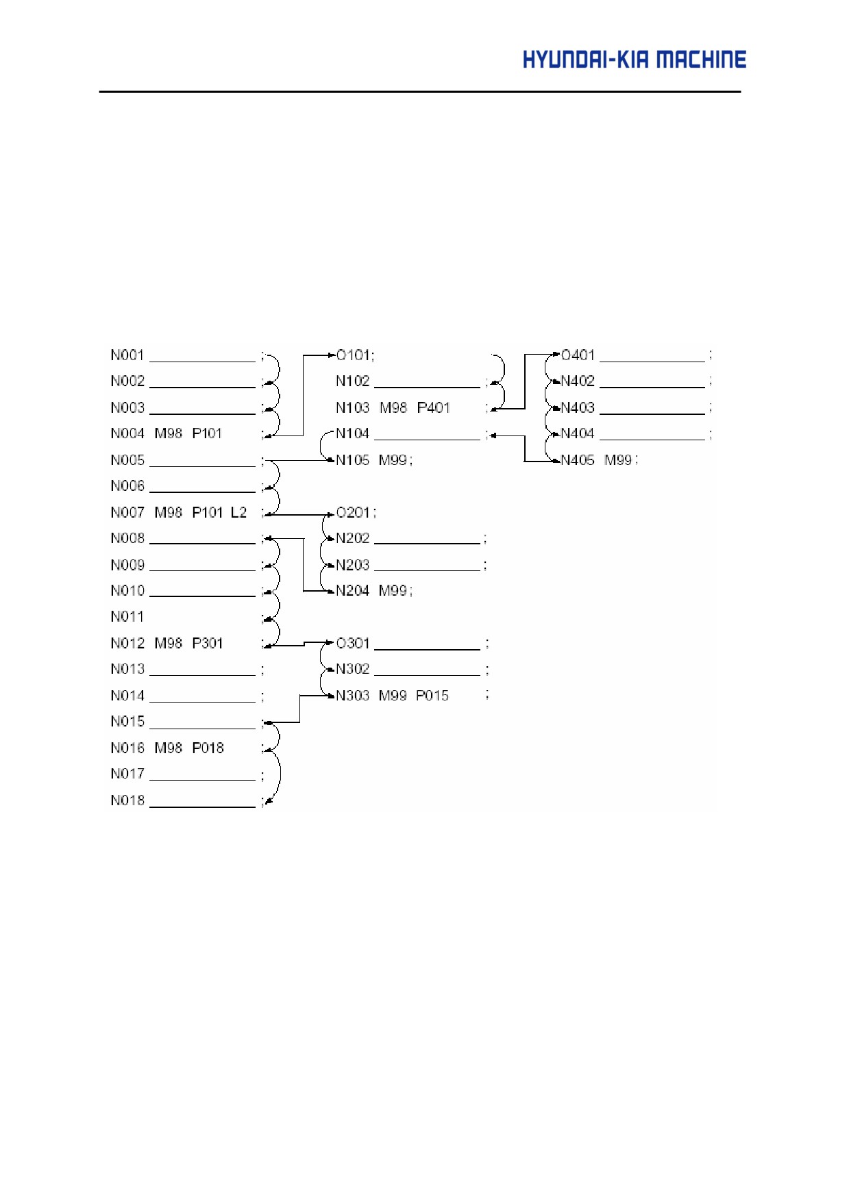
Sub Program Call
(Ex)
Main Program
Sub Program
3-11
4.
Head Stock
4-1.
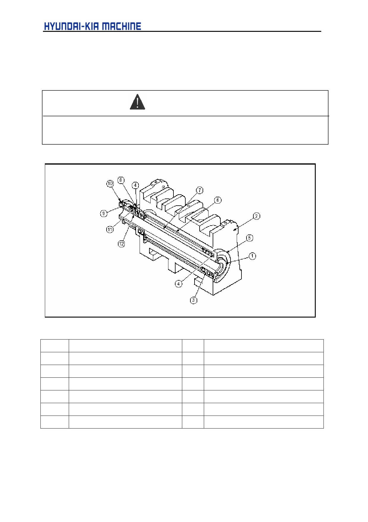
SUPER KIA TURN 100
CAUTION
Before operating the machine, sufficient warm up the Head Stock.
• The Head Stock is A2-5
Fig. 3-3 Head Stock (SUPER KIATURN 100)
No.
Part Name
No.
Part Name
1
Spindle
7
Collar "B"
2
Head Body
8
Rear Flange
3
Bearing
9
O-Ring
4
Labyrinth
10
Hex. Bolt
5
Front Flange
11
Spindle Pulley
6
Collar "A"
12
Key
3-12
III. SPECIFICATION
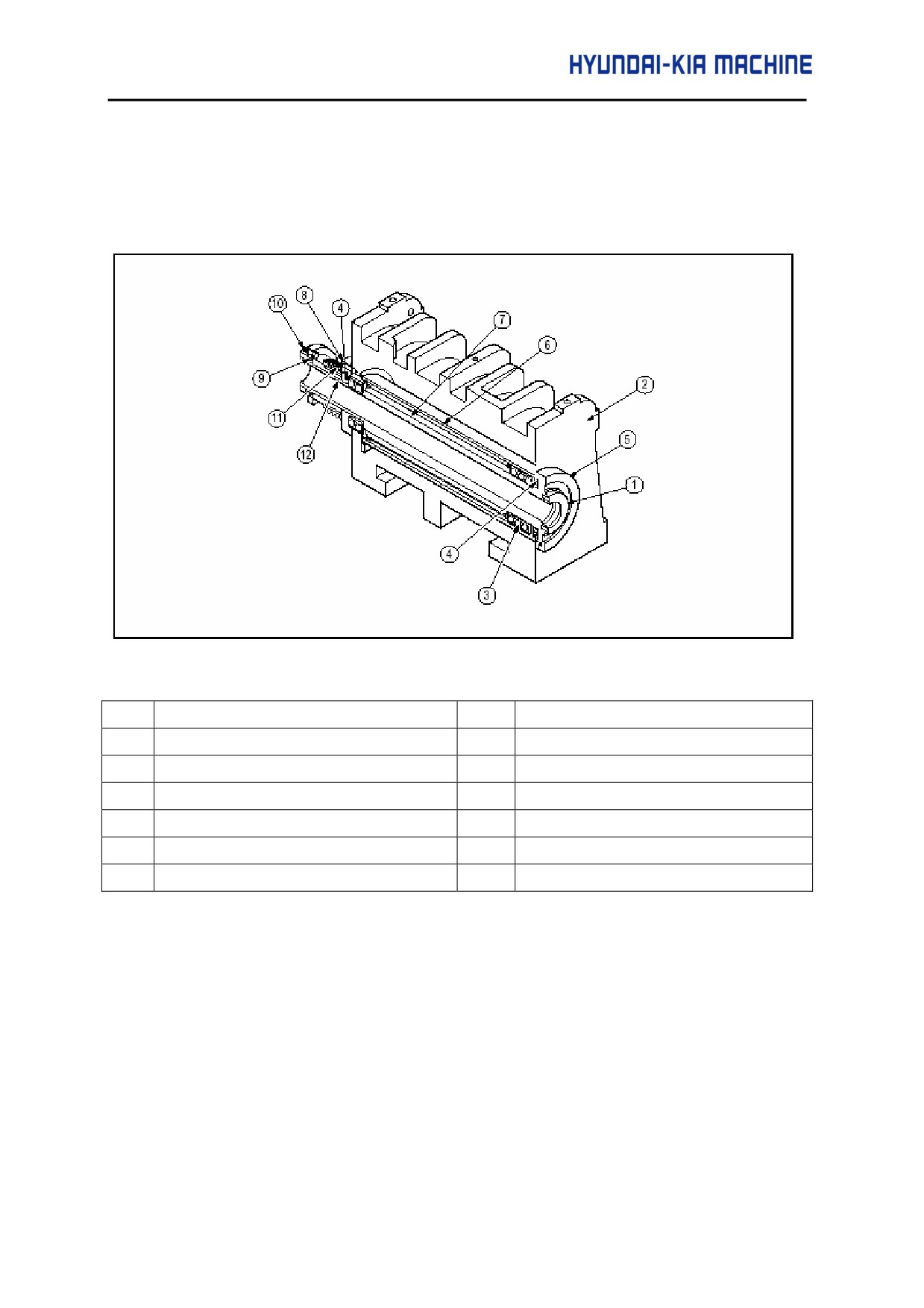
4-2. SUPER KIA TURN 200
• The Head Stock is A2-6
Fig. 3-4 Head Stock (SUPER KIATURN 200)
No.
Part Name
No.
Part Name
1
Spindle
7
Collar "B"
2
Head Body
8
Rear Flange
3
Bearing
9
O-Ring
4
Labyrinth
10
Hex. Bolt
5
Front Flange
11
Spindle Pulley
6
Collar "A"
12
Key
3-13
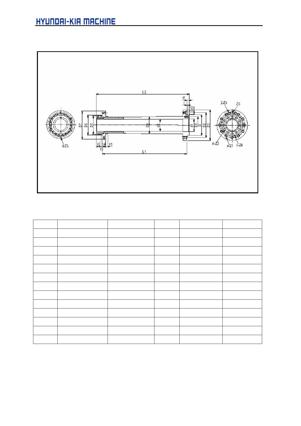
4-3.
Major Dimensions of Head Stock
Fig. 3-5 Major Dimensions of Head Stock
mm (in)
No.
SKT 100
SKT 200
No.
SKT 100
SKT 200
D
82.17(3.235)
106.375(4.188)
t2
22.4
21
D1
62(2.56)
90(3.54)
t3
9
5
D2
104.8(4.125)
133.4(5.25)
t4
20
17.5
D3
135(5.31)
210(8.26)
t5
3
18.5
D4
90(3.54)
110(4.33)
L1
474.8
535.1
D5
87(3.43) [100(3.94)]
130(5.12)
L2
519.2
575.4
D6
150(5.91)
145(5.71)
n-Z1
11-M12
11-M12
D7
176(6.93)
190(7.48)
n-Z2
8-M8
8-M6
d1
54(2.13)
78(3.07)
n-Z3
6-M10
6-M10
d2
53(2.09)
78(3.07)
n-Z4
6-M10
3-M8
d3
16(0.63)
19.05(0.75)
Z5
10
10.2
t
4.75(0.187)
4.8(0.189)
Z6
M6
M8
t1
13(5.12)
14.3(0.563)
Z6
50
30
3-14
III. SPECIFICATION
5.
Chuck and Rotary Cylinder
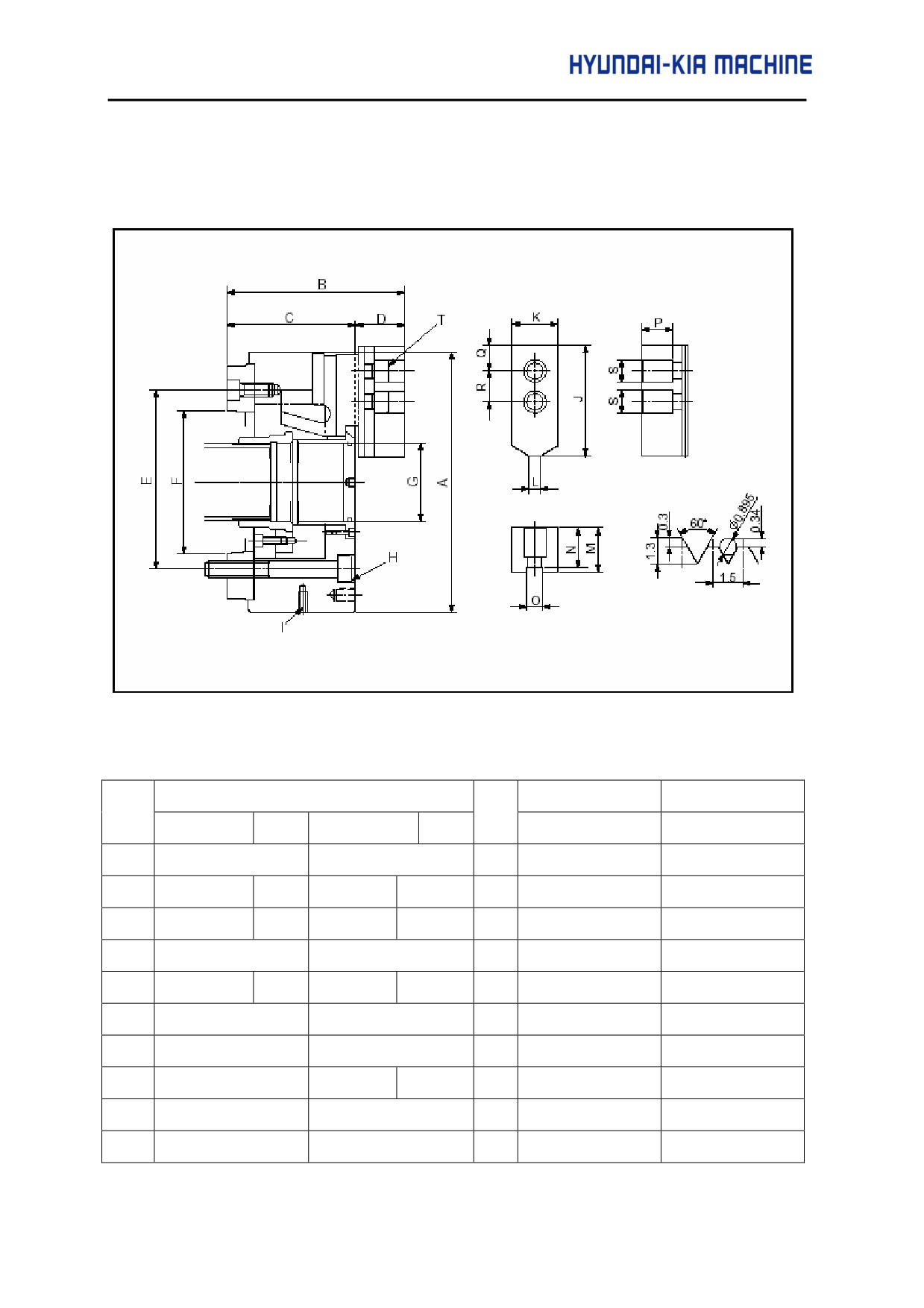
5-1.
Hollow Chuck Major Dimensions
Fig. 3-6 Major Dimensions of Hollow Chuck and Soft Jaw
mm
No.
SKT100
No.
SKT100
SKT200
SAMCHUNREE
SMI
SAMCHUNREE
SMI
SAMCHUNREE/SMI
SAMCHUNREE/SMI
A
Ø 169
Ø 210
K
35
40
B
123
122
147
146
L
6
8
C
91
90
103
102
M
28
40
D
32
44
N
23
35
E
104.8
110
133.4
140
O
12
16
F
82.56
106.375
P
20
26
G
Ø 46
Ø 52
Q
15
20
H
M10-95L
M12-110L
M12-105L
R
20
25
I
2-M10
2-M10
S
Ø17.5
Ø 20
J
72
85.5
T
M10-32L
M12-32L
3-15
5-2.
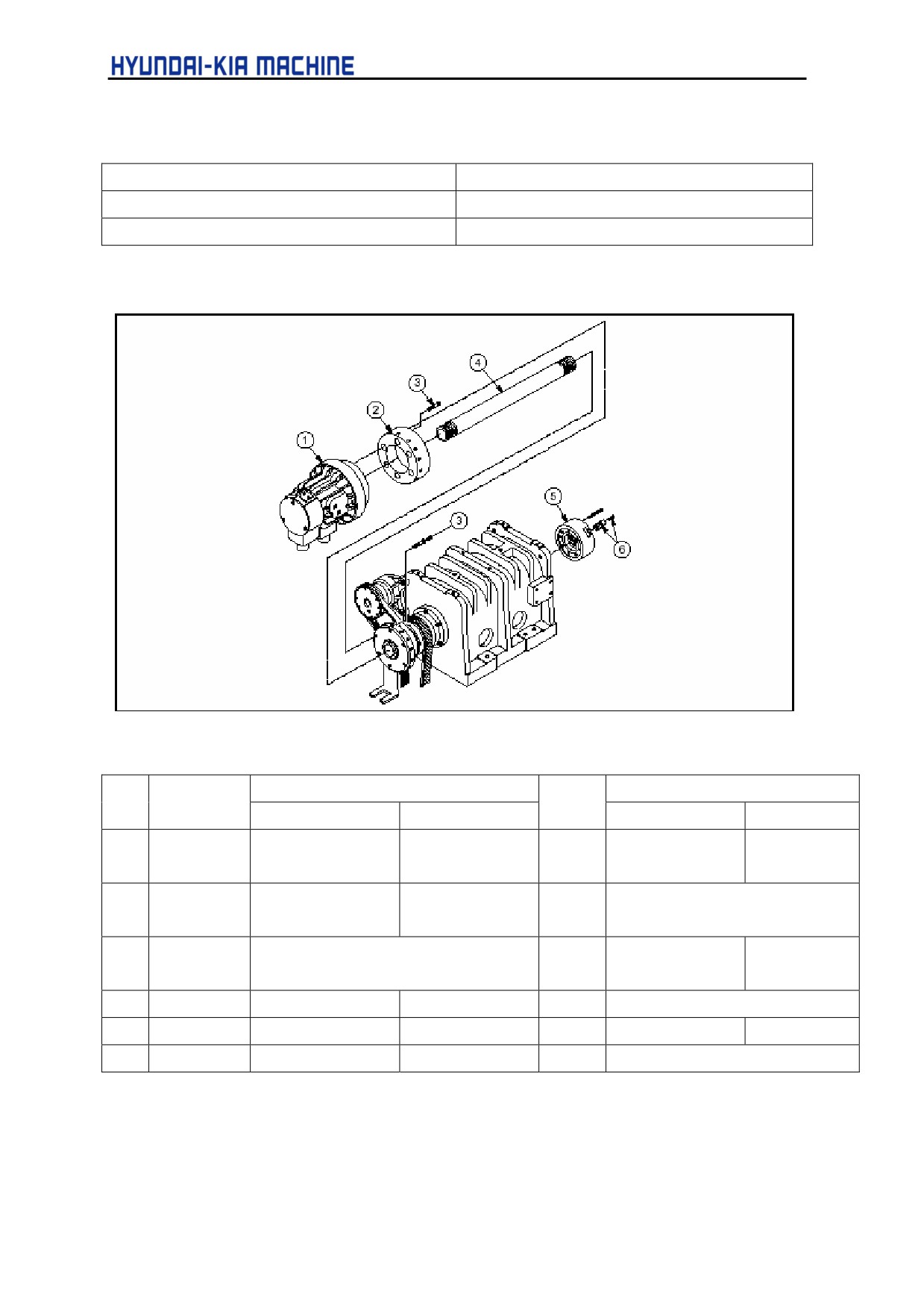
SUPER KIATURN 100 Hollow Chuck (6', 0165)
Name
Manufacturer
Chuck
SAMCHUNREE, SMI
Cylinder
SAMCHUNREE. SMI
5-2-1. Connecting Parts for Rotary Cylinder
Fig. 3-7 Connecting Parts for Cylinder
No.
Item
Item No.
Qty.
Remarks
SAMCHUNREE
SMI
SAMCHUNREE
SMI
1
Hydraulic
1680-11-302-0
1344-11-101-3
1
SYH1239
HHH35CA6
Cylinder
2
Cylinder
1680-11-304-0
1344-11-313-0
1
Flange
3
SCREW,
SM1101010030
12
M10 x 30L
HEX S/C
4
Draw Tube
1680-11-303-0
1654-11-306-0
1
5
Chuck
1680-11-301-0
1344-11-205-1
1
HAS-06
HH037M6
6
Soft Jaw
1674-11-317-0
KK007003
1 SET
3-16
III. SPECIFICATION
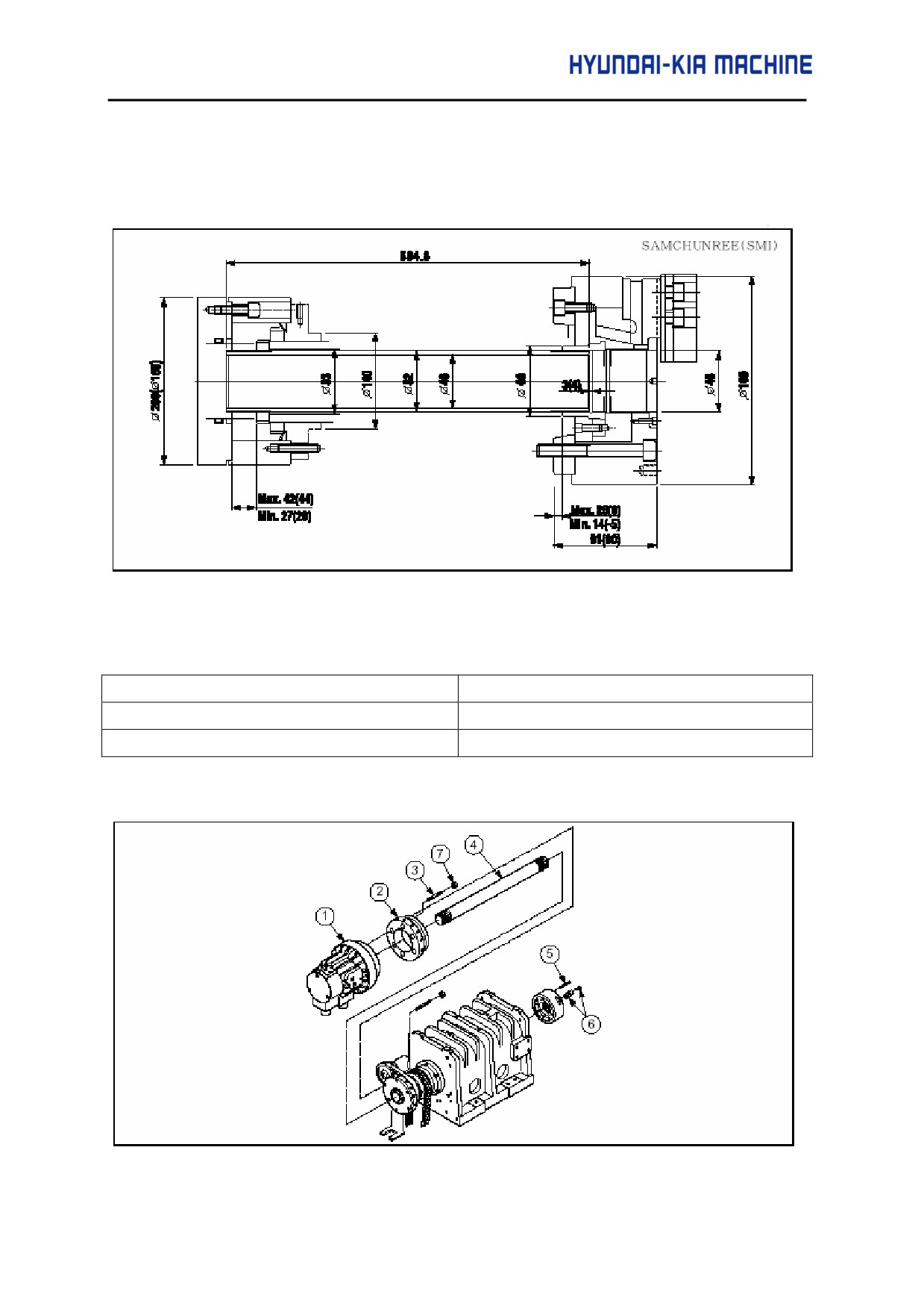
5-2-2. Major Dimension
mm (in)
Fig. 3-8 Major Dimensions of Connecting Parts for Cylinder
5-3.
SUPER KIATURN 200 Hollow Chuck (8", Ø 210)
Name
Manufacturer
Chuck
SAMCHUNREE, SMI
Cylinder
SAMCHUNREE, SMI
5-3-1. Connecting Parts for Rotary Cylinder
Fig. 3-9 Connecting Parts for Cylinder
3-17
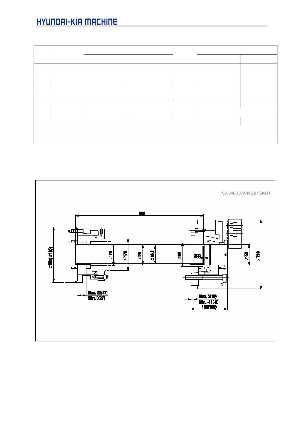
No.
Item
Item No.
Qty.
Remarks
SAMCHUNREE
Hwacheon
SAMCHUNREE
Hwacheon
1
Hydraulic
1742-11-450-1
1742-11-118-1
1
SYH1239
HH36CA8
Cylinder
2
Cylinder
1742-11-447-0
1742-11-202-0
1
Flange
3
Stud bolt
SM 1008010030
4
M10 x 30L
4
Draw Tube
1742-11-432-0
1
5
Chuck
1742-11-449-0
1742-11-117-0
1
HAS-06
H037M8
6
Soft Jaw
1742-11-454-0
1742-11-443-0
1 SET
7
Hex. Nut
SM 1201001000
4
M10
5-3-2. Major Dimension
mm (in)
Fig. 3-10 Major Dimensions of Connecting Parts for Cylinder
3-18
III. SPECIFICATION
6.
Tool Post
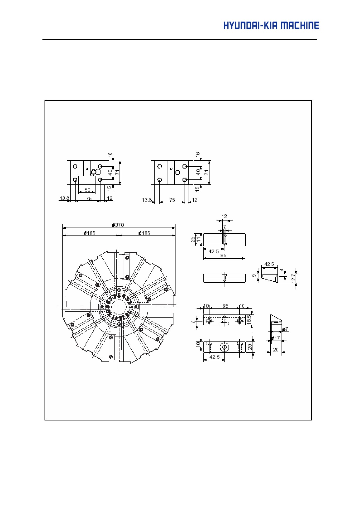
6-1. Turret
mm (in)
Fig. 3-11 Turret (SUPER KIATURN 100/200)
3-19
6-2.
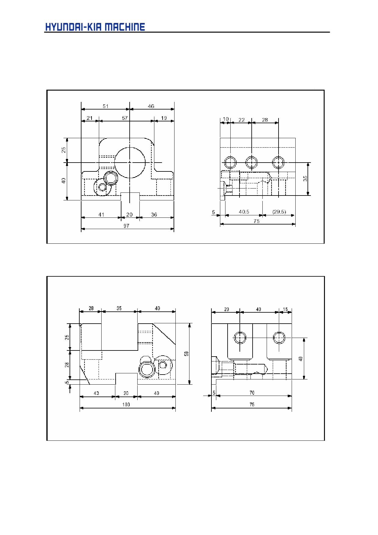
SUPER KIATURN 100
• Base Holder
mm (in)
Fig. 3-12 Base Holder
mm (in)
Fig. 3-13 Face Grooving Base Holder
3-20
III. SPECIFICATION
6-3.
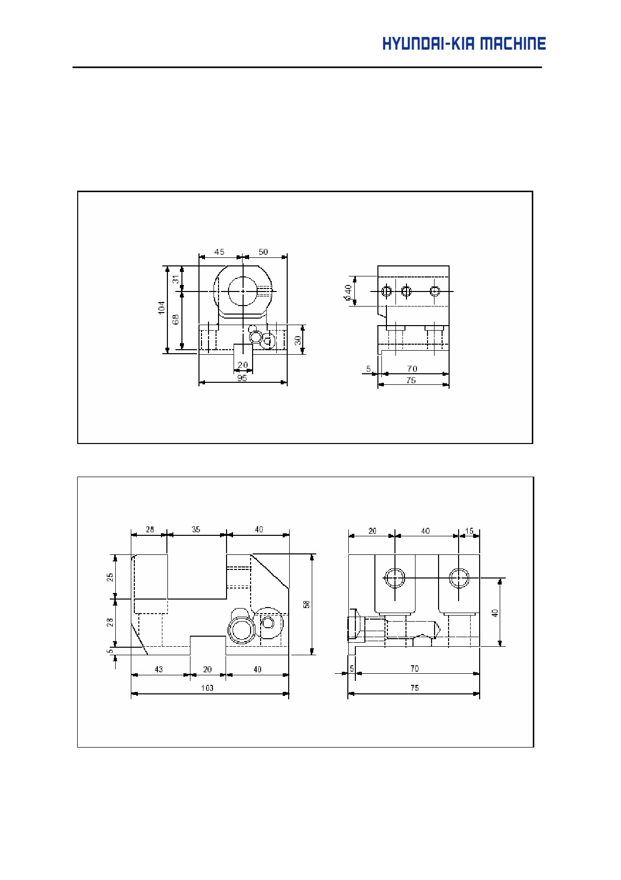
SUPER K1ATURN 200
• Base Holder
mm (in)
Fig. 3-14 I.D. Base Holder
mm (in)
Fig. 3-15 Face Grooving Base Holder
3-21
IV
TRANSPORT & INSTALLATION
IV TRANSPORT & INSTALLATION
1.
General
4-1
2.
Layout of Machine
4-1
3.
Transporter
4-2
3-1. Crane
4-3
3-2. Fork Lift
4-5
4.
Installation
4-6
4-1. Preparation to Install
4-6
4-1-1 Installation Condition
4-6
4-1-2. Foundation Work
4-7
4-2. Foundation Work
4-8
4-2-1. Without Using Foundation Bolt
4-9
4-2-2. Using Foundation Bolt (Optional)
4-9
5.
Adjustment of Level
4-10
6.
Cleaning
4-12
7.
Lubrication & Oiling
4-13
7-1. Hydraulic Oil
4-13
7-2. Oiling Wet Moving Part in the X-and Z-axes
4-13
7-3. Oiling Hydraulic Chuck
4-14
8.
Coolant
4-15
9.
Electric Power and Wiring
4-16
9-1. Power Switch
4-17
9-2. Wiring to Machine from Power Switch
4-17
9-3. Changing Electric Units According to Voltage and
Frequency
4-18
9-3-1. Tab Changing for Controlling Transformer
4-18
9-3-2. External Transformer
4-19
9-4. Grounding
4-19
10.
Disassembling and Cleaning Shipment Fixture
4-21
11.
Check Before Test Working
4-22
12.
Required Before Test Working
4-22
12-1. Tool Moving Range
4-22
12-2. Tool Interference Diagram
4-23
IV. TRANSPORT & INSTALLATION
1.
General
(1) This CNC lathe contains three major elements - Body of machine, the Electric Control Panel,
Hydraulic Unit, and etc. and each of them is connected with wires and hydraulic pipes.
(2) Sine all devices are attached to the body of machine, you can move it as necessary without
overhauling the machine.
(3) There are 2 methods of moving by crane or fork lift.
(4) To achieve the desired working, you should follow the installation procedures given in this
manual.
2.
Layout of Machine
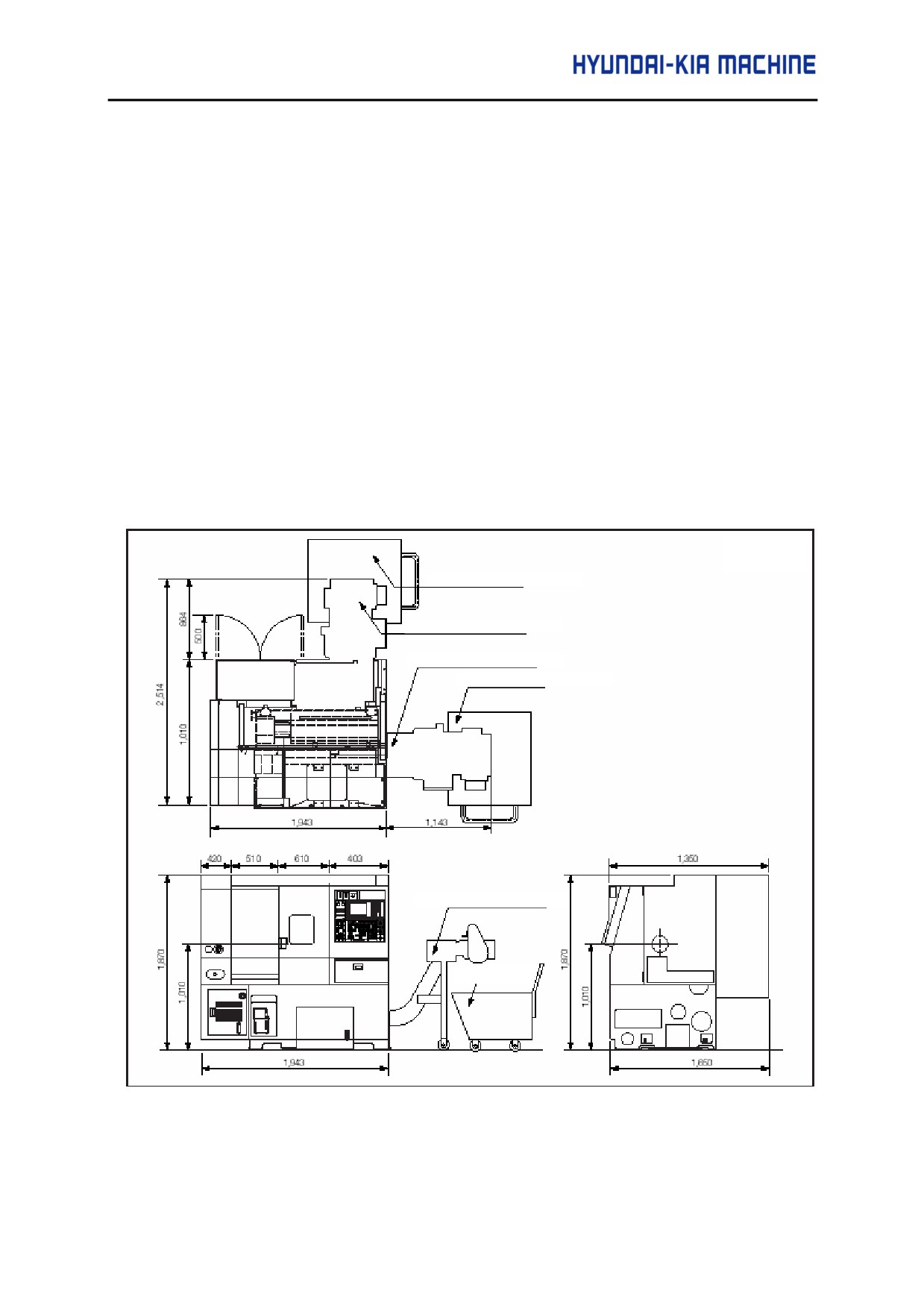
Figure 4-1 shows the dimension concerned when attaching special accessories, ie. the chip box
and chip conveyor to the body of machine.
Unit: mm
Chip wagon (Option)
Chip wagon (Front type, Option)
Chip wagon (Rear type, Option)
Chip wagon (Option)
Chip wagon (Rear type, Option)
Chip wagon
(Option)
Fig. 4-1 Layout of Machine
4-1
3.
Transporter
(1) There a 2 transporting methods by means of crane or forklift.
WARNING
1.
When transporting the machine, be careful not to crash with other objects.
2.
Never stand or walk under high-lifted machine.
CAUTION
1.
Prior to transporting the machine, check each part of the machine is properly fixed to each
other.
2.
When lifting the machine, slowly do a job, ensuring a full balance.
3.
Be careful not to give a shock to the body of machine, t he Electric Control Panel and other
electric devices.
4.
Transport the coolant tank after removing it from the body of machine.
4-2
IV. TRANSPORT & INSTALLATION
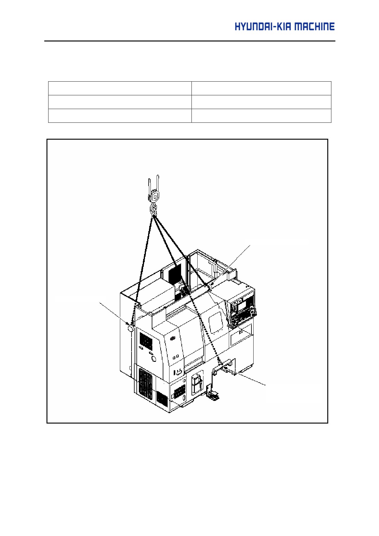
3-1. Crane
Name
Weight
SUPER KIATURN 100
3,800 Kgf (38000N)
SUPER KIATURN 200
3,900 Kgf (39000N)
Bed Edge
Bed Edge
Transporting Fixture
Fig. 4-2 Transport by Crane
4-3
(1) The crane-working method is shown in Figure 4-2.
(2) When transporting by crane, ensure the followings.
1) Adjust the center by moving the saddle and cross slide so that they are loaded at the
center of hanged angle.
2) Set the angle of wire rope within 90° and to 60° if possible.
3) The capacities of wire rope and crane are as follows.
c Wire rope ... over 16mm in diameter
d Crane
over 5ton in load
4) Place where the wire rope is to be attached.
c
Both edges of bed
d Fixture for transporting
CAUTION
1.
With the machine lifted slightly, check all sides for balance and the rope is reached to the cover or
other parts.
2.
When more than 2 persons have to lift the machine, they should work together, communicating
each other.
3.
Do not use rusty or shorted wire ropes.
4. When lifting the machine, slowly do a job. If the wire rope is tightened, temporarily stop and check an
eye bolt is clamped and then lift up to the desired height.
5.
When pulling down, also do it slowly. Just before reached the floor, stop it and check the position
and then pull down completely.
6.
Only the experienced-personnel should perform a crane work.
4-4
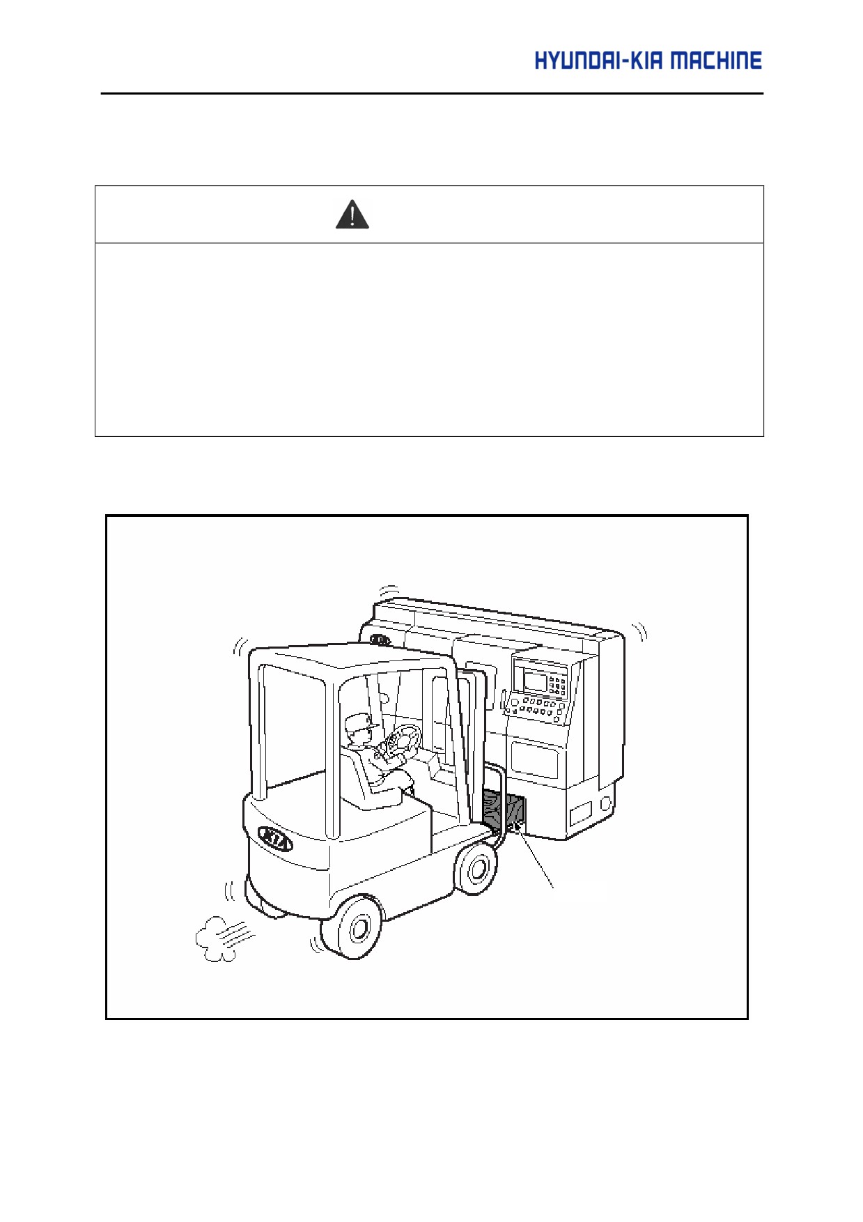
IV. TRANSPORT & INSTALLATION
3-2. Fork Lift
CAUTION
1.
Only who has the forklift driver* s license can convey the machine by forklift.
2.
To avoid damage around the protruded part of machine, the task should be performed by two
persons, of which one is a supervisor.
3.
Put down the machine slowly not to give a shock on the floor.
4.
Hold wood between the forklift and the machine for lifting.
• Insert the fork into guide slot in the lower front of the machine.
Wood
Fig. 4-3 Transport by Fork Lift
4-5
4.
Installation
WARNING
1.
Before installing the machine, read and understand the safety notice thoroughly in this
manual.
2.
While installing, there should be no oil or water on the floor to prevent the workers from
slipping.
3.
Before working, check again it is installed at a proper place.
4-1. Preparation to Install 4-1-1. Installation Condition
• When installing the machine, avoid places as below.
a. Under direct ray of sun and near by heating elements and where the indoor temp.
b. Heavy dust and high humidity area.
c. Near the vibrating machine.
d. Where foundation is weak.
e. Where ground uneven or inclined.
CAUTION
1.
If you have to install the machine around vibrating objects, install the suck absorbing pad
around it.
2.
It is required to prepare space for maintenance, if optional accessory was attached (See Fig.
4-1).
4-6
IV. TRANSPORT & INSTALLATION
4-1-2. Foundation Work
When installing the machine tool, the foundation should be solid. This ensures the best
integrity of cutting in the machine. But, it greatly depends on the nature of ground where the
factory is located, for example whether it is rocky or filled-in. Observe the general knowledge of
machine tool and the related notice.
CAUTION
1.
The strength of ground has to be over 5 ton/mm2 and the thickness over 300mm.
2.
The Foundation has to be over 300mm of bed in circumference.
3.
When installing the suck absorbing pad, place it around boundary of foundation.
4.
Do not use the foundation which is divided into small concrete blocks only supporting
each level.
It is very important to located the machine in proper place. You have to check the interruption
of machine operator which chip removing and maintenance like; pulling chip cart removing
covers for maintenance.
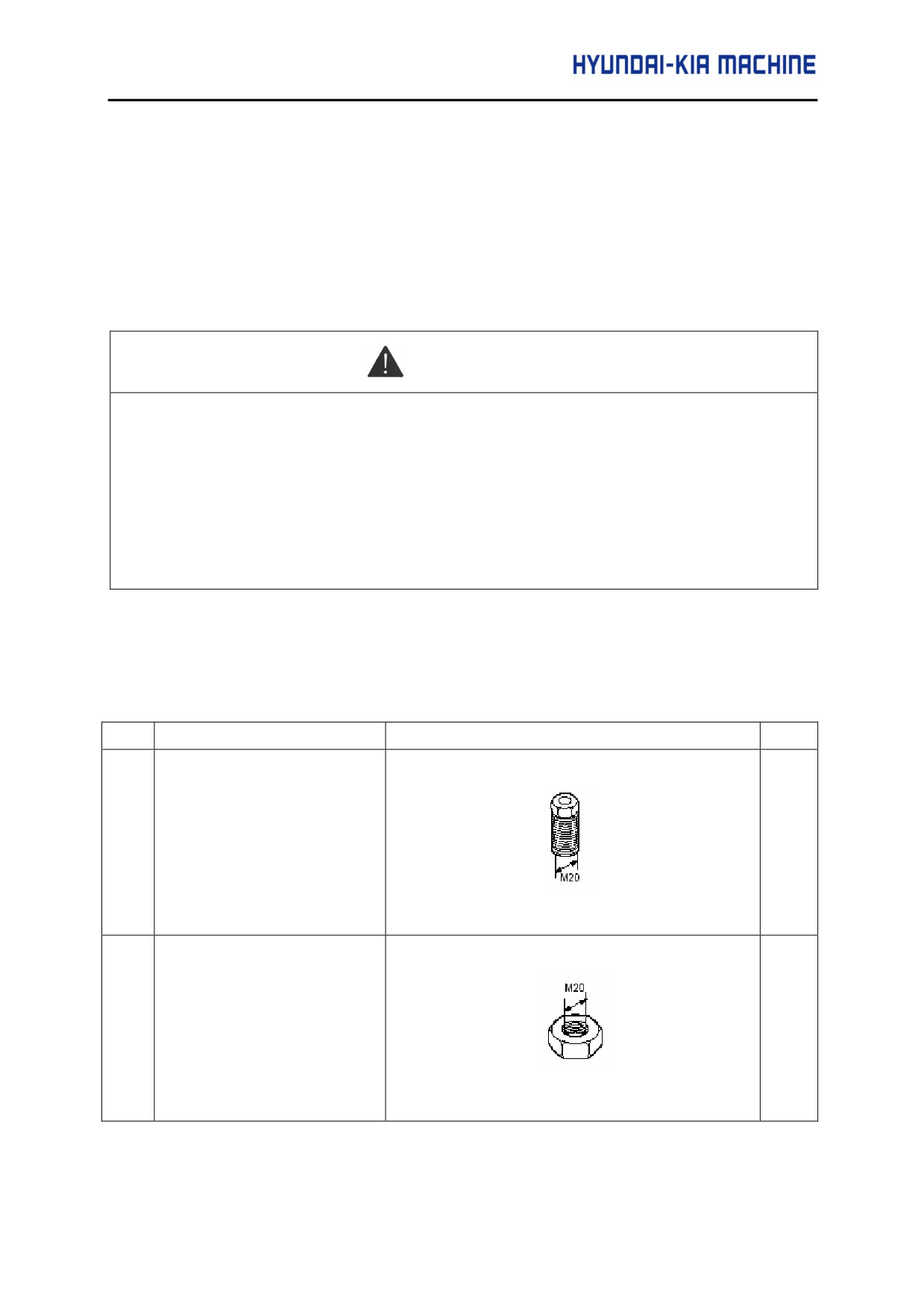
No.
Name and Number
Figure
Qty.
SM1017020080
1
(Leveling Bolt)
6
SM1217002000
2
(Leveling Nut)
6
4-7