FANUC AC Servo Amplifiers βi Series. Description Manual (B-65322EN/02) - page 10
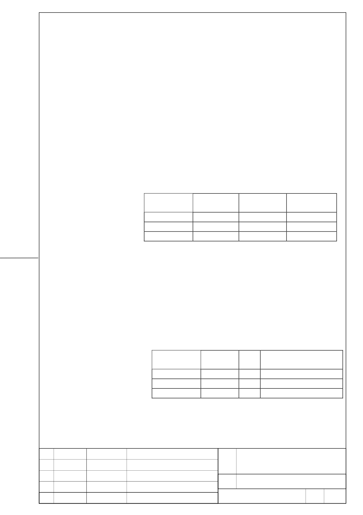
13. Heat disspaton
The amount of heat dissipation depends on the SVM model and the current that flows
through the servo motor. For the current that flows through a servo motor, reference the
continuous rated current of each servo motor. (For the continuous rated current of each
servo motor, refer to the servo motor descriptions.) As the current that flows through a servo
motor, the root-mean-square value of the current that flows through an actual servo motor on
a machine can be used. The amount of heat dissipation indicated below assumes the use of
HRV2.
(1) Total amount of heat dissipation
The total amount of heat dissipation is calculated
according to the following expression:
Total amount of heat dissipation= a + Ka1 × b1
a: Amount of heat dissipation determined by the SVM
model [W]
Ka1: Coefficient determined by the SVM [W/Arms]
b1: Current flowing through the servo motor [Arms]
Total amount of heat dissipation
a
K
Name
Specification
[W]
[W/Arms]
SVM1-10HVi
H001
20
Ka1: 10.8
SVM1-20HVi
H002
20
Ka1: 11.1
SVM1-40HVi
H003
20
Ka1: 11.1
(2) Residual amount of heat in the cabinet
By placing the heat sink section outside the cabinet, the
residual amount of heat in the cabinet can be calculated
according to the expression below.
Residual amount of heat in the cabinet= a + Kb1 × b1
a: Amount of heat dissipation determined by the SVM
model [W]
Kb1: Coefficient determined by the SVM [W/Arms]
b1: Current flowing through the servo motor [Arms]
Residual amount of heat in the cabinet
Specificatio
a
K
Name
n
[W]
[W/Arms]
SVM1-10HVi
H001
20
Ka1: 2.2
SVM1-20HVi
H002
20
Ka1: 2.2
SVM1-40HVi
H003
20
Ka1: 1.1
FANUC SERVO AMPLIFIER
TITLE
βi series DESCRIPTIONS
DRAW.
No.
B-65322EN/02-02
EDIT
DATE
DESIGN
DESCRIPTION
FANUC LTD
Page
17 / 17
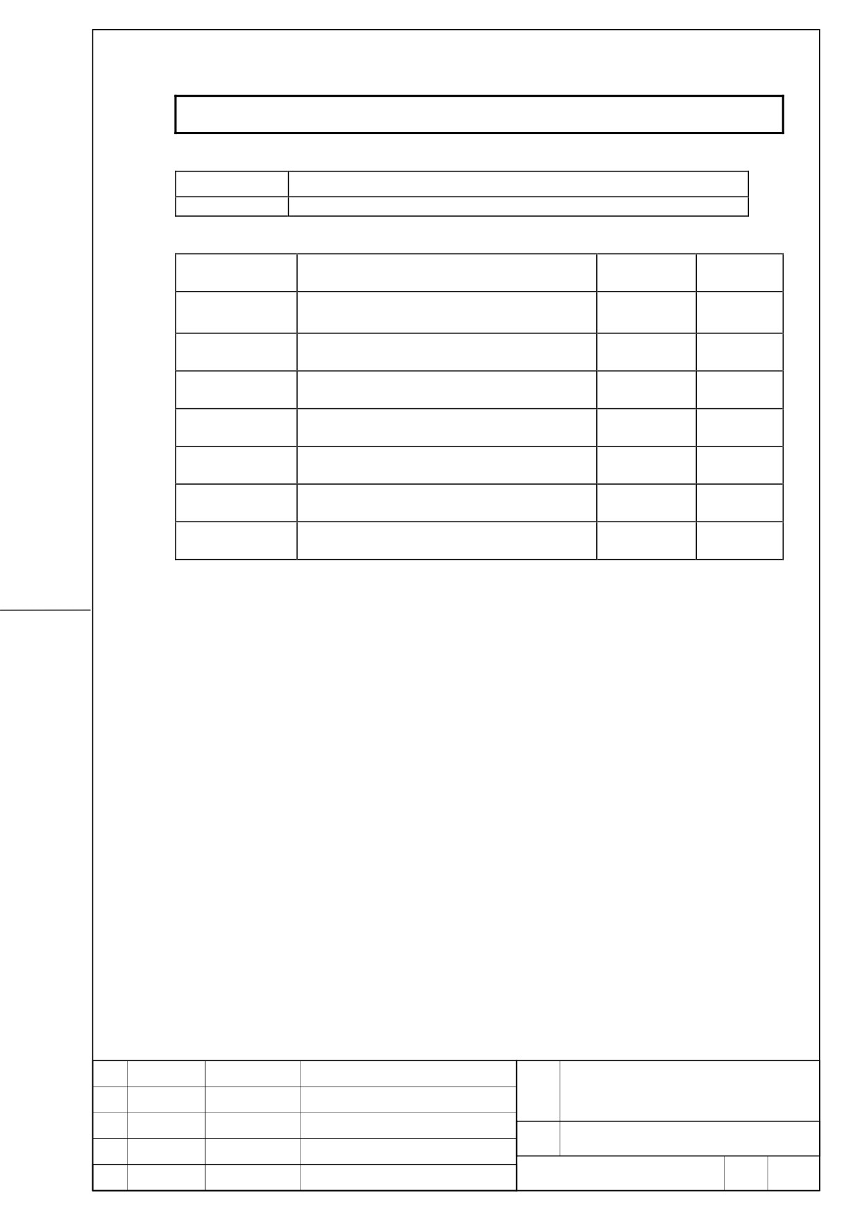
FANUC SERVO AMPLIFIER βiSV 20/20 DESCRIPTIONS
1. Type of applied documents
Name
FANUC SERVO AMPLIFIER βiSV 20/20 DESCRIPTIONS
Spec. No./Ver.
B-65322EN/02-03
2. Summary of Change
Group
Name / Outline
New, Add
Applicable
Correct, Del
Date
Basic Function
Optional
Function
Unit
Maintenance
Parts
Notice
Correction
Another
Addition of βiSV 20/20
New
2005. 7
FANUC SERVO AMPLIFIER
TITLE
βiSV 20/20 DESCRIPTIONS
DRAW.
No.
B-65322EN/02-03
01
05.07.21
K.Inaba
Add newly
EDIT
DATE
DESIGN
DESCRIPTION
FANUC LTD
Page
1 / 23
βiSV 20/20 DESCRIPTIONS
This documents describes about the specification of βiSV 20/20.
Please refer to FANUC SERVO AMPLIFIER βi series DESCRIPTIONS (B-65322EN/02) about
contents without in this.
(Note)
This Servo amplifier βiSV 20/20 is available to use combining Series 0i-MODEL C/
0i Mate-MODEL C.
All specifications and designs are subject to change without notice.
FANUC SERVO AMPLIFIER
TITLE
βiSV 20/20 DESCRIPTIONS
DRAW.
No.
B-65322EN/02-03
EDIT
DATE
DESIGN
DESCRIPTION
FANUC LTD
Page
2 / 23
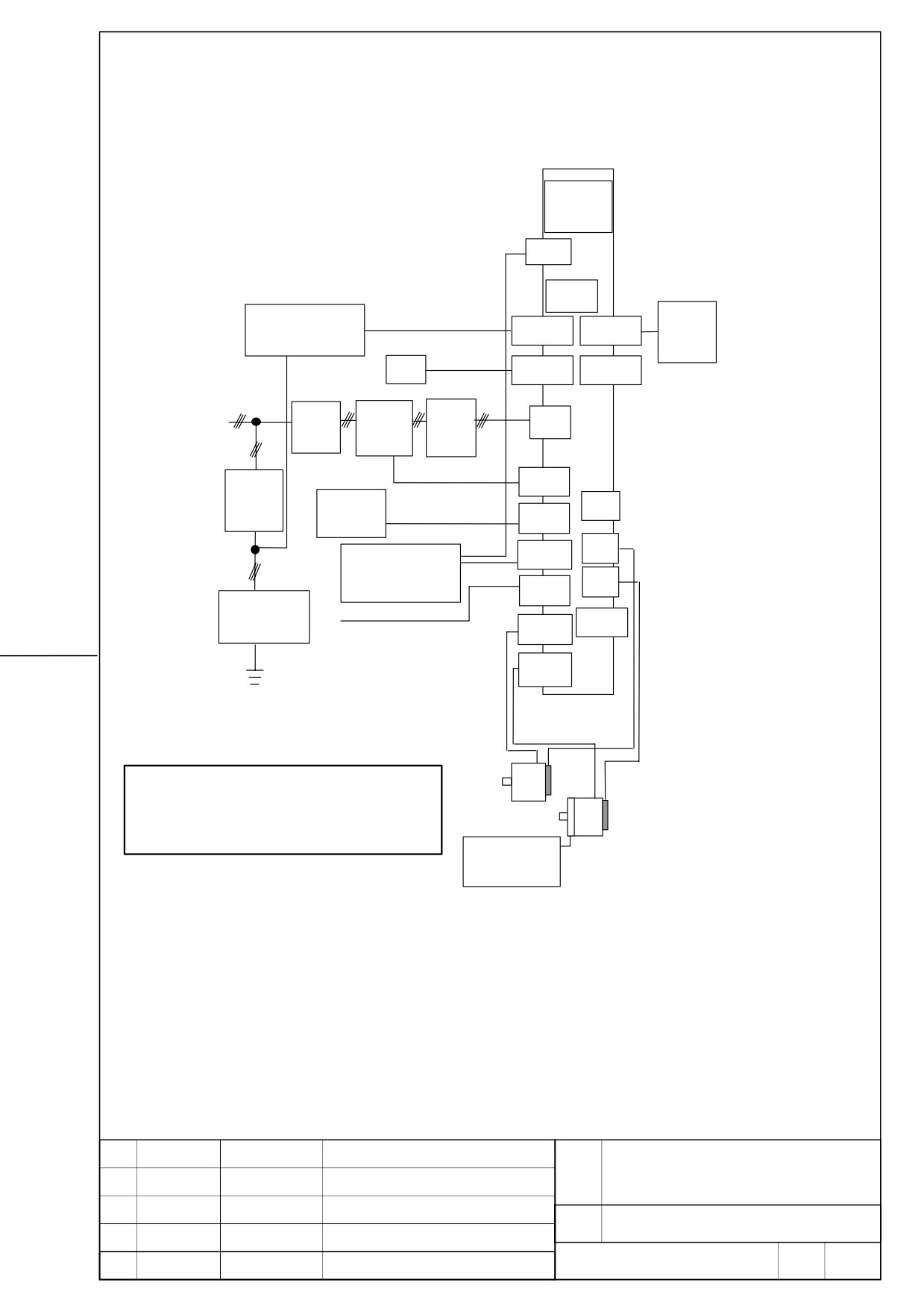
1. Configuration
βiSV
20/20
TB
FUSE
Stabilized power supply
Battery
CXA19B
CXA19A
case
DC24V
Optical cable
NC
COP10A
3 phase
COP10B
200V to 240VAC
Magnetic
AC line
Breaker
CZ4
contactor
filter
Magnetic contactor
5A circuit
control signal
CX29
Emergency
breaker
JX5
stop switch
CX30
Emergency stop signal
CXA20
JF1
Separated regenerative
discharge resistor
JF2
CX36
Lighting
Power failure signal
surge absorber
CX5X
CZ5L
CZ5M
CAUTION
1 A circuit breakers, magnetic contactor, and AC line filter
are always required.
2 Use the stabilized 24VDC power supply for the amplifier.
24VDC power supply for the amplifier and 24VDC power
supply for the motor brake cannot be shared.
24V power supply
for motor brake
FANUC SERVO AMPLIFIER
TITLE
βiSV 20/20 DESCRIPTIONS
DRAW.
No.
B-65322EN/02-03
EDIT
DATE
DESIGN
DESCRIPTION
FANUC LTD
Page
3 / 23
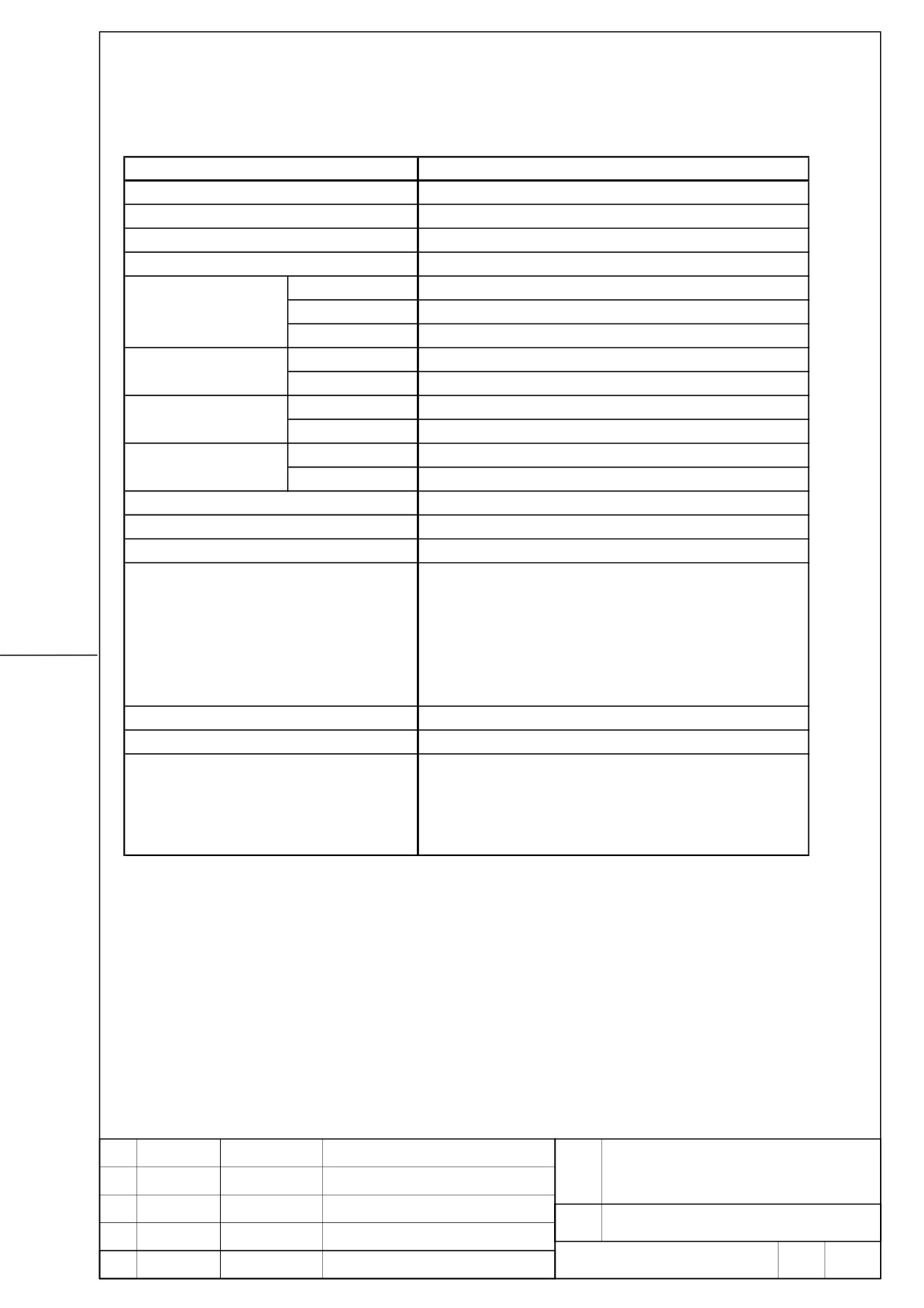
2. Specification
Item
βi SV 20/20
Interface
FSSB
Unit Designation
A06B-6136-H201
Power P.C.B.
A16B-3200-0642
Control P.C.B.
A20B-2101-0290
Input Voltage
AC 200-240 V (+10%,-15%)
50 / 60 Hz
Main Power For
Current at 50Hz
7.6Arms
Three Phase Supply
Rated Capacity
2.7kVA
Control
Input Voltage
DC 24 V (+10%, -10%)
Power supply
Input Current
0.8 Arms
L-Axis
6.5Arms
Rated Output Current
M-Axis
6.5Arms
L-Axis
20 Ap
Current Limit Value
M-Axis
20 Ap
Servo control
HRV2, HRV3
Main Circuit Control Method
Sine Wave PWM Control with Transistor Bridges
Servo output frequency range
0-667Hz
- High Current
- IPM Abnormal
- High Voltage of DC Link
- Low Voltage of DC Link
Warning and protectivefunctions
- Overheat of Discharge Resistor
- Low Voltage of Control Power Supply
- FSSB Communication Error
- Locked Fan Motor
Ambient Temperature Range
0 to +55 degrees Celsius
Weight
3.9kg
Regererative resistor
(16ohm, 100W no-wind condition)
(16ohm, 200W no-wind condition)
Option
(16ohm, 400W wind velocity 2m/s condition)
Separated AC line filter
Separated battery
FANUC SERVO AMPLIFIER
TITLE
βiSV 20/20 DESCRIPTIONS
DRAW.
No.
B-65322EN/02-03
EDIT
DATE
DESIGN
DESCRIPTION
FANUC LTD
Page
4 / 23
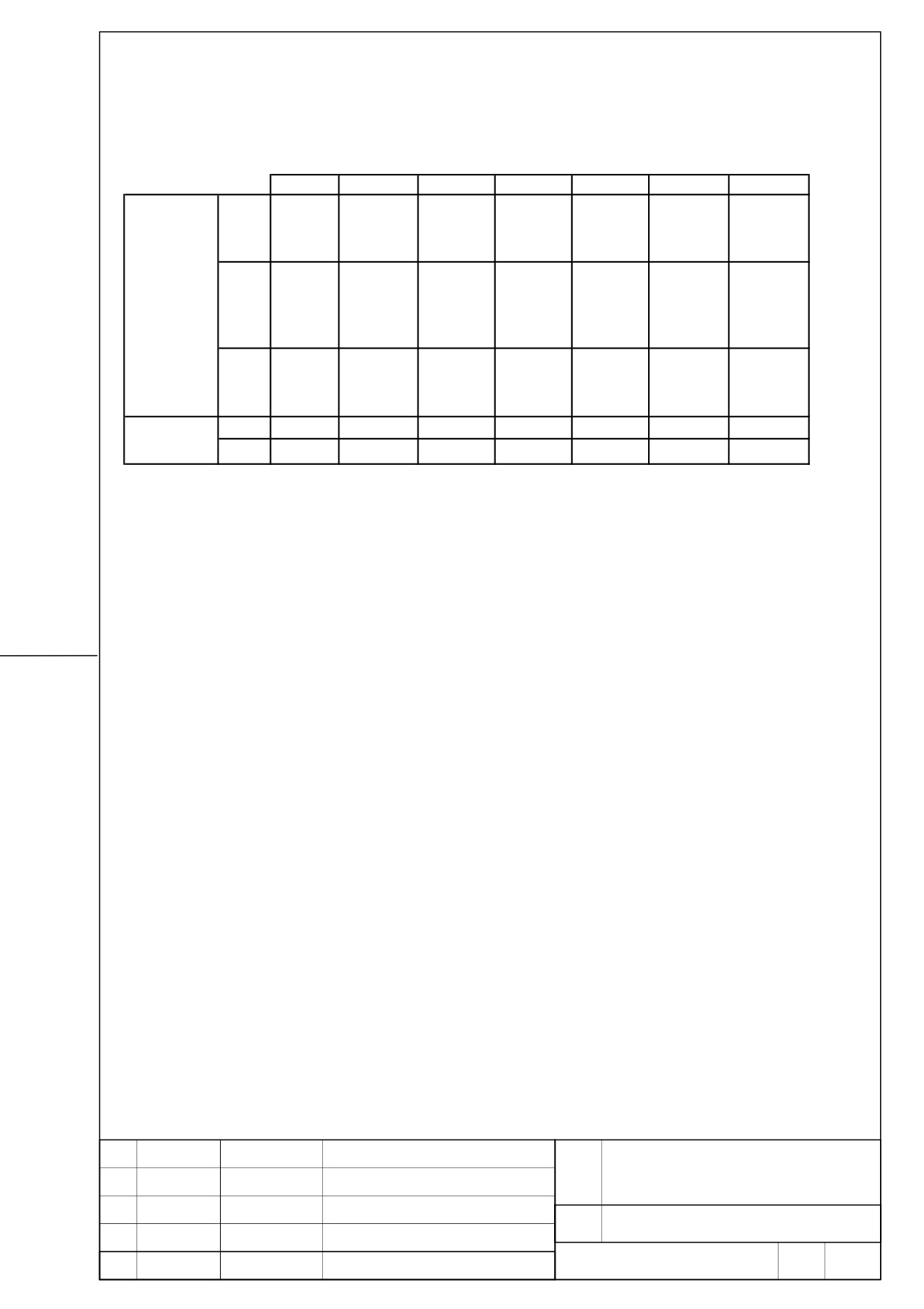
3. Applicable motors
0.4
0.5
1
2
4
8
12
αi F1
αi F2
/ 5000
/ 5000
αi F
(20A)
(20A)
αi S2
αi S4
/ 5000
/ 6000
/ 5000
αi S
(20A)
(20A)
MOTOR
βi S0.4
βi S0.5
βi S1
βi S2
βi S4
βi S8
βi S12
/5000
/6000
/6000
/4000
/4000
/3000
/2000
βi s
(20A)
(20A)
(20A)
(20A)
(20A)
(20A)
(20A)
SV 20/20
L axis
O
O
O
O
O
O
O
axis
O
O
O
O
O
O
O
FANUC SERVO AMPLIFIER
TITLE
βiSV 20/20 DESCRIPTIONS
DRAW.
No.
B-65322EN/02-03
EDIT
DATE
DESIGN
DESCRIPTION
FANUC LTD
Page
5 / 23
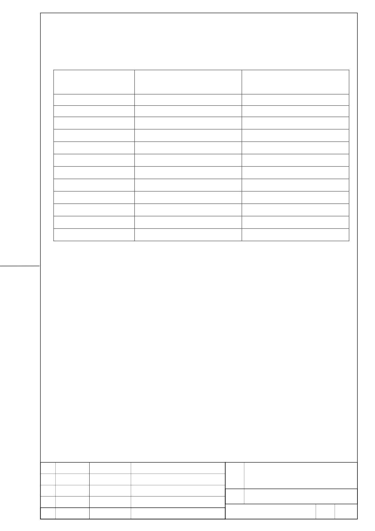
4. Selection of breaker, electromagnetic contactor, and AC line filter
Please refer to the following table and select it. For details, please refer to B-65322/02EN.
Servo motor
Continuous rating current
Power supply capacity
[Arms]
[kVA]
(Reference value)
(Reference value)
βiS 0.4/5000
0.6
0.2
βiS 0.5/6000
1.4
0.47
βiS 1/6000
2.3
0.77
βiS 2/4000
2.2
0.77
βiS 4/4000
3.3
1.2
βiS 8/3000
5.4
1.9
βiS 12/2000
6.3
2.2
αiF 1/5000
2.2
0.77
αiF 2/5000
3.3
1.2
αiS 2/5000
3.3
1.2
αiS 2/6000
4.5
1.6
αiS 4/5000
4.5
1.5
5. Derating
Consider derating as shown below, according to ambient temperature.
The solid line is a derating line for use when HRV2, while the dotted line is a derating line for
use when HRV3 is applied.
FANUC SERVO AMPLIFIER
TITLE
βiSV 20/20 DESCRIPTIONS
DRAW.
No.
B-65322EN/02-03
EDIT
DATE
DESIGN
DESCRIPTION
FANUC LTD
Page
6 / 23
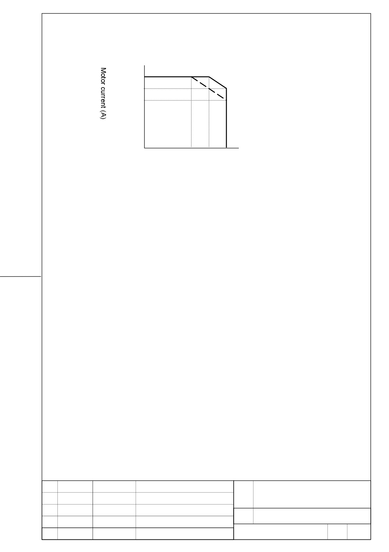
Motor current derating
6.5
5.2
4.6
35
45
55
Ambient temperature (Degree)
FANUC SERVO AMPLIFIER
TITLE
βiSV 20/20 DESCRIPTIONS
DRAW.
No.
B-65322EN/02-03
EDIT
DATE
DESIGN
DESCRIPTION
FANUC LTD
Page
7 / 23
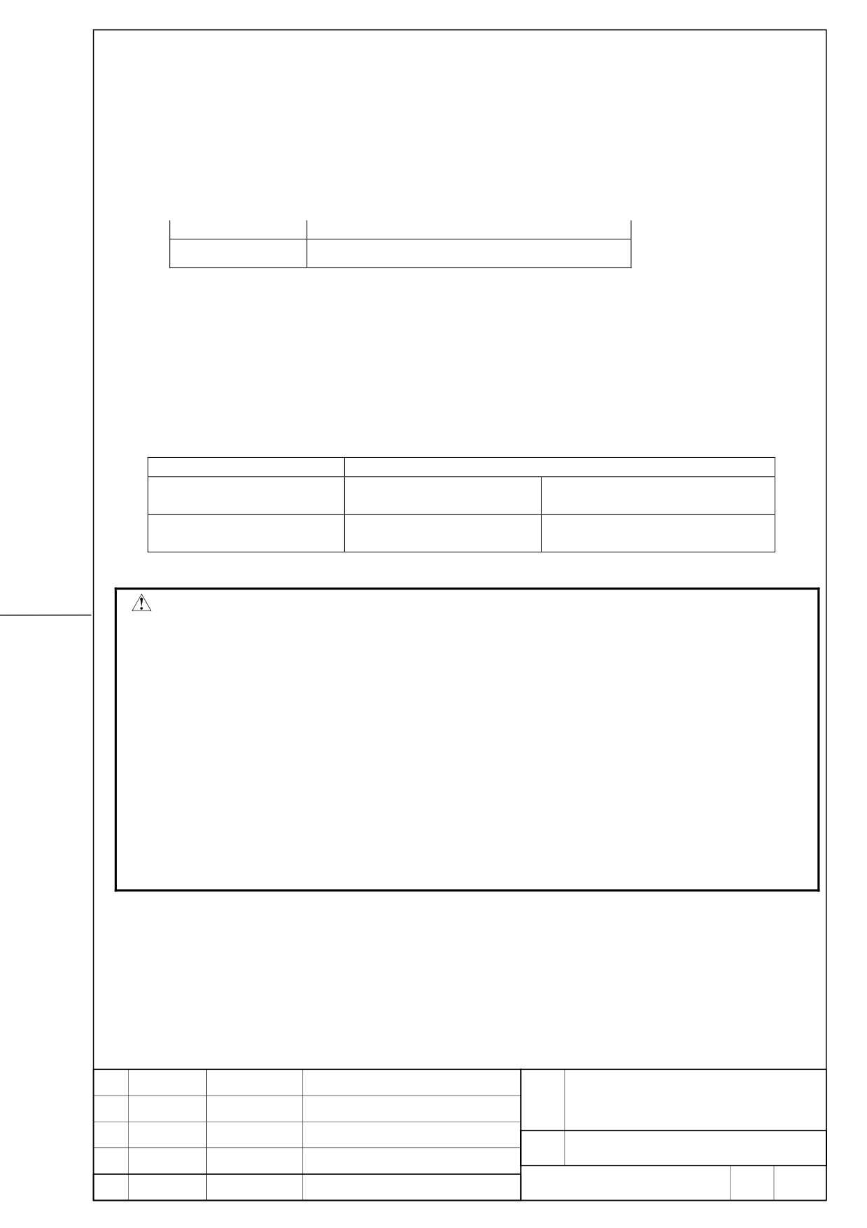
6. Regeneration discharge resistor
6.1. When separated regenerative discharge resistor is not needed.
When the regeneration energy per regenerative cycle is below the following amounts of
energy [J], regeneration discharge resistor is unnecessary.
Table6.1 Permissible regenerative energy amount (Reference value)
Amplifier model
Permissible regenerative energy amount
25[J]
βiSV 20/20
Refer to Section [I. SVM ] of B-65322EN/02 for details about calculation method of the
regeneration energy per regenerative cycle.
6.2. When separated regenerative discharge resistor is needed.
When the regeneration energy per regenerative cycle exceeds the amount of permission
regenerative energy of servo amplifier, DC link overvoltage alarm or abnormal of
regeneration discharge may occur. In this case, regenerative discharge resistor is needed.
Table6.2 Capacity of regenerative discharge resistor
Specification
Capacity of regenerative discharge resistor
A06B-6130-H404
100W
-
(Note1) (Note2)
No -wind condition
A06B-6089-H500
200W
400W
(Note1)
No -wind condition
Wind velocity 2m/s condition
Cautions
z Please install into the cabinet, which fulfills the following conditions so that cutting fluid,
oil mist, cutting waste, etc. may not adhere to regeneration discharge resistor.
So, please install in the environment of the pollution degree 2 level specified to "IEC
60664-1."
In order to satisfy a pollution degree 2 under the severe environment of a machine tool,
it is necessary to install in a cabinet with which it is generally satisfied of IP54.
If the cabinet does not have a structure for preventing materials that adversely affect
regenerative discharge resistor from gettinng into the cabinet, normal operation and
safety may fail. So, special care should be taken.
z
Incorrect connection may cause to damage the amplifier.
FANUC SERVO AMPLIFIER
TITLE
βiSV 20/20 DESCRIPTIONS
DRAW.
No.
B-65322EN/02-03
EDIT
DATE
DESIGN
DESCRIPTION
FANUC LTD
Page
8 / 23
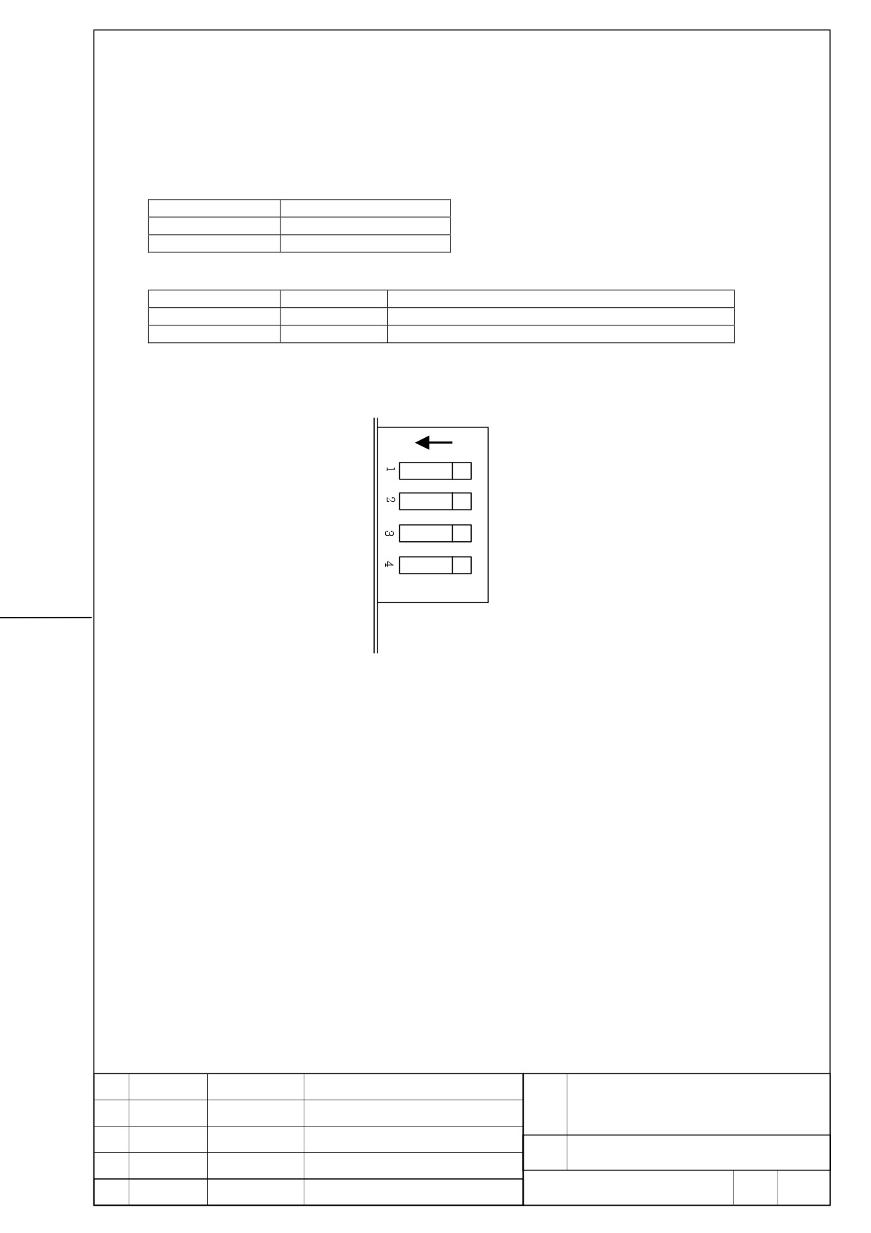
7. Setup switch (For DC alarm level)
Since the switch of four channels is in the front of a servo amplifier for regeneration
resistance protection, please make it the following setup.
Setup of SW1, SW2
Switch
Setup
Switch1
OFF
Switch2
OFF
Setup of SW3, SW4
SW3
SW4
Separated regenerative discharge resistor
ON
ON
A06B-6130-H404 (Note1)
OFF
ON
A06B-6089-H500
ON
FANUC SERVO AMPLIFIER
TITLE
βiSV 20/20 DESCRIPTIONS
DRAW.
No.
B-65322EN/02-03
EDIT
DATE
DESIGN
DESCRIPTION
FANUC LTD
Page
9 / 23
8. Power supply specification
8.1. Three-phase input power supply for motor power
- Nominal rating voltage: 200V to 240VAC
- Allowable voltage fluctuation: -15% - +10%
- Frequency: 50/60Hz
- Allowable frequency fluctuation: ±2Hz
- Power supply impedance : Voltage fluctuation by load (at
maximum output) not be exceed 7%.
- Power supply Unbalance: ±5% or less of rated voltage
NOTE
The allowable voltage fluctuation is a change
observed for several minutes. It is not a continuous
change.
8.2. Single-phase input for control power
Please be sure to use a regulated power supply for 24V power supply for amplifier.
Common use with 24V power supply for motor brakes cannot be performed.
- Nominal rating voltage: 24VDC
- Allowable voltage fluctuation: ±10% (Including momentary
variations)
- Power supply capacity
Power supply capacity per amplifier
FSSB interface
0.8A
FANUC SERVO AMPLIFIER
TITLE
βiSV 20/20 DESCRIPTIONS
DRAW.
No.
B-65322EN/02-03
EDIT
DATE
DESIGN
DESCRIPTION
FANUC LTD
Page
10 / 23
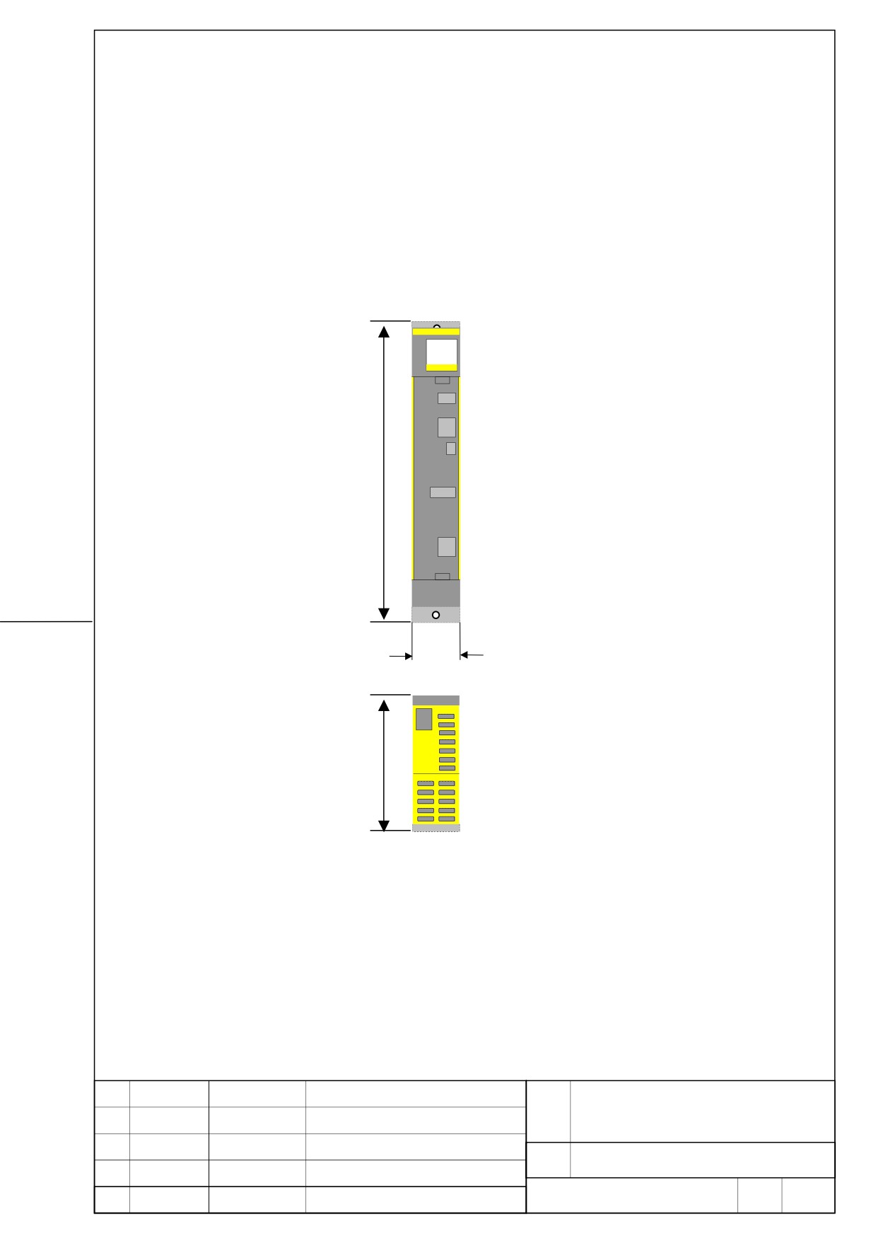
9. External dimention/ Panel cut-out drawing/ maintenance area
9.1. External dimension
βiSV 20/20
Without outer fin
380
60
172
FANUC SERVO AMPLIFIER
TITLE
βiSV 20/20 DESCRIPTIONS
DRAW.
No.
B-65322EN/02-03
EDIT
DATE
DESIGN
DESCRIPTION
FANUC LTD
Page
11 / 23
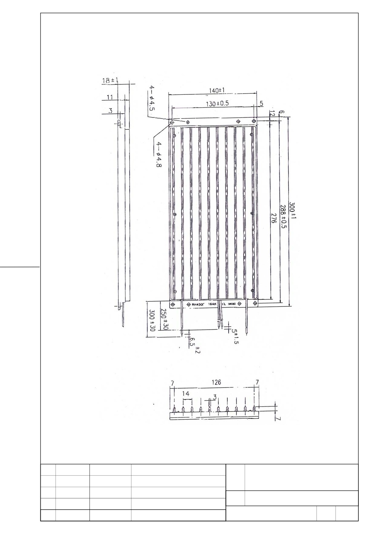
External dimension Regenerative discharge resistor (A06B-6130-H404)
FANUC SERVO AMPLIFIER
TITLE
βiSV 20/20 DESCRIPTIONS
DRAW.
No.
B-65322EN/02-03
EDIT
DATE
DESIGN
DESCRIPTION
FANUC LTD
Page
12 / 23
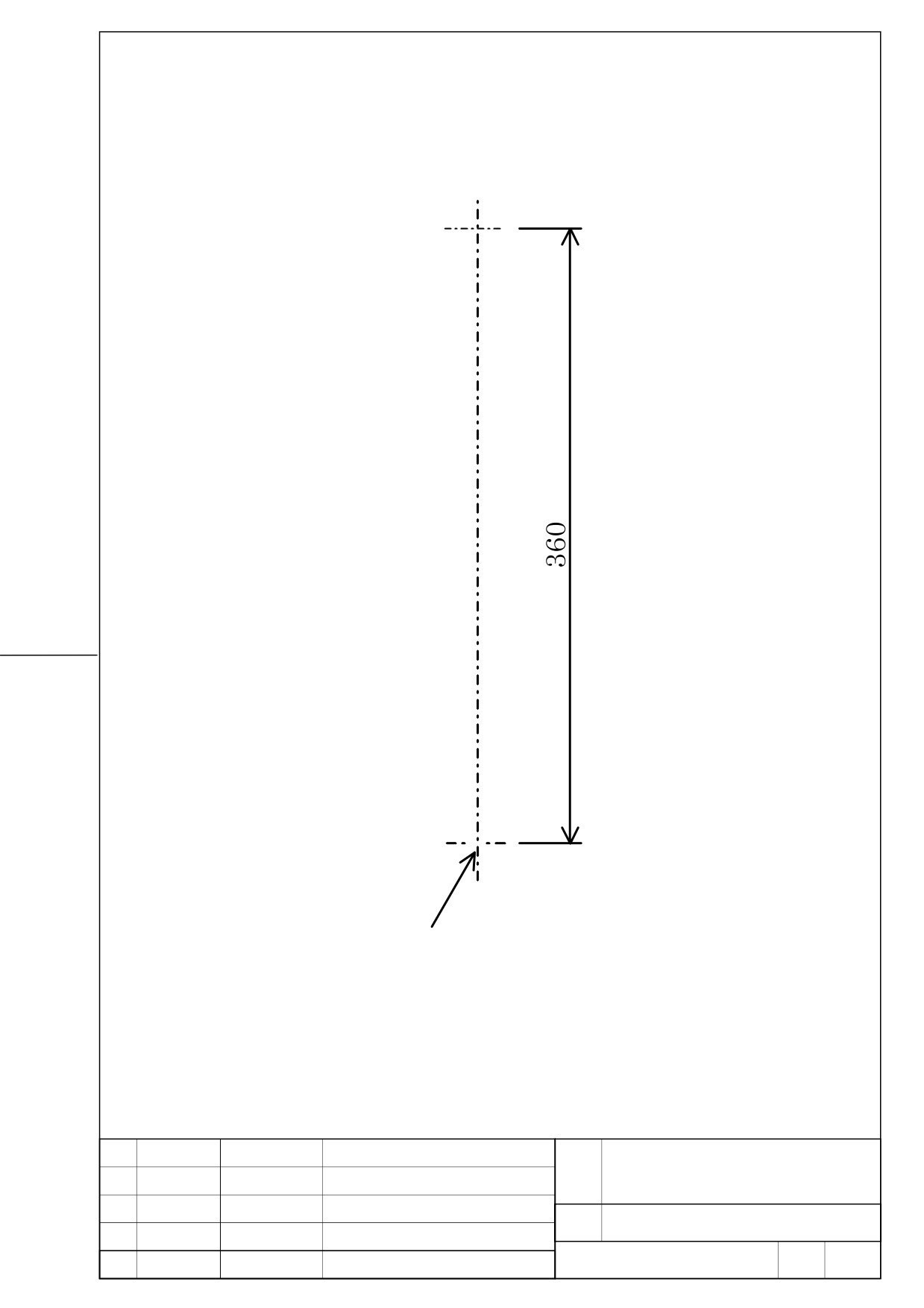
9.2. Panel cut-out drawing
βiSV 20/20
○
○
2-M5
FANUC SERVO AMPLIFIER
TITLE
βiSV 20/20 DESCRIPTIONS
DRAW.
No.
B-65322EN/02-03
EDIT
DATE
DESIGN
DESCRIPTION
FANUC LTD
Page
13 / 23
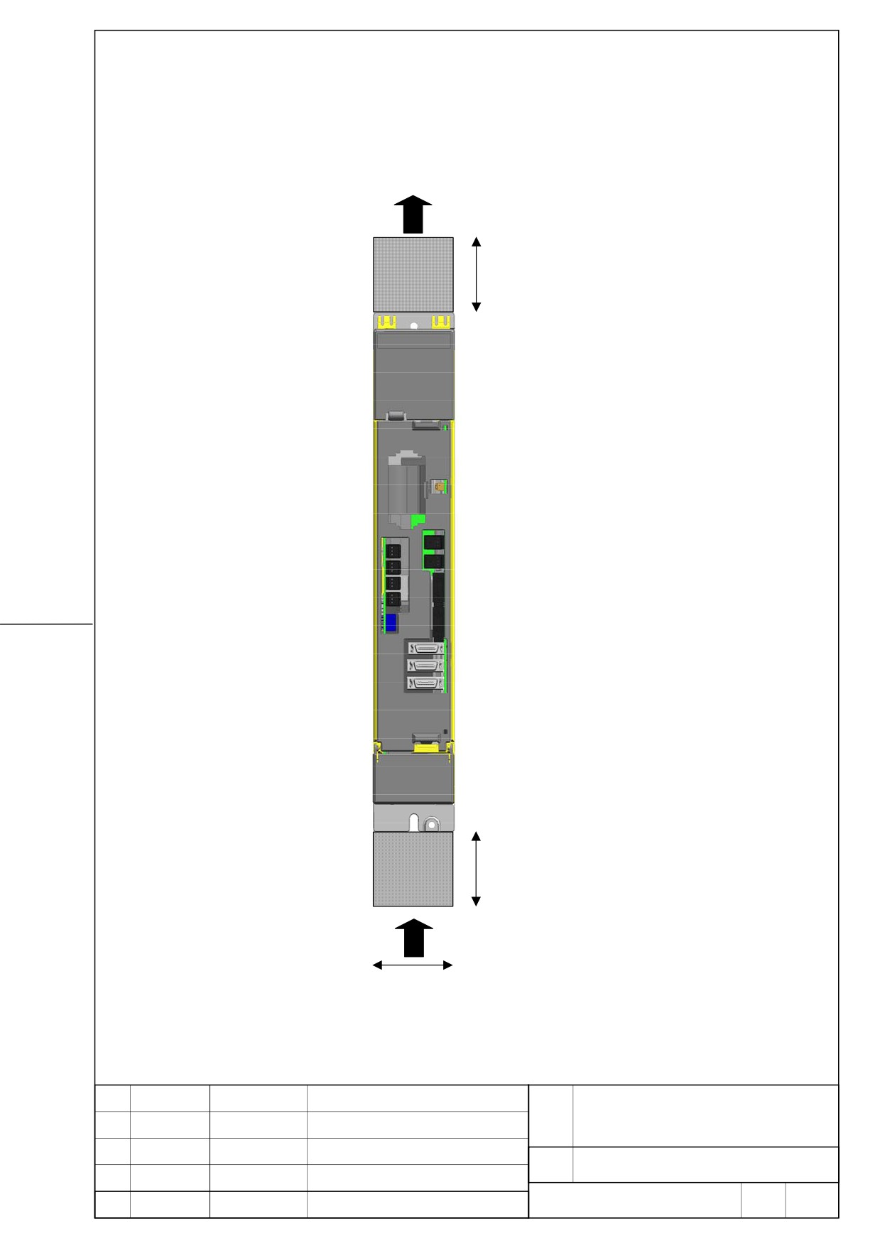
9.3. Maintenance area
AIR FLOW
50mm
50mm
60mm
FANUC SERVO AMPLIFIER
TITLE
βiSV 20/20 DESCRIPTIONS
DRAW.
No.
B-65322EN/02-03
EDIT
DATE
DESIGN
DESCRIPTION
FANUC LTD
Page
14 / 23
10. Power failure detecting function
The power failure detect function aiming at the gravity axis fall prevention at the time of a
power failure was occurred.
Please refer to the section [11.5] for connection details.
In case of using this function, please add an uninterruptible power supply (UPS) etc. to be
able to maintain the control source (DC 24V) of CNC and amplifier after a power failure
occurs until mechanical brake operates.
Specification
2-axes amplifier βiSV output a power failure detect signal from a connector CX36, when
power failure is occurred.
The drop of three-phase circuit AC voltage inputted into the connector “CZ4” of 2-axes
amplifier βiSV is detected.
CZ4 input voltage range: 0 V-AC240V+10% 3φ 50Hz/60Hz±2Hz
CZ4 power failure detect voltage: AC165V±10V
Detection delay time is established so that it may not react sensitively to instantaneous
power failure.
Detection delay time: 8msec~17msec
(Note)
The detect condition is simultaneous three-phase circuit AC voltage drop.
Therefore, it may be unable to detect a power failure correctly on following conditions.
1.
Power failure (phase interruption) as only one phase drop.
2.
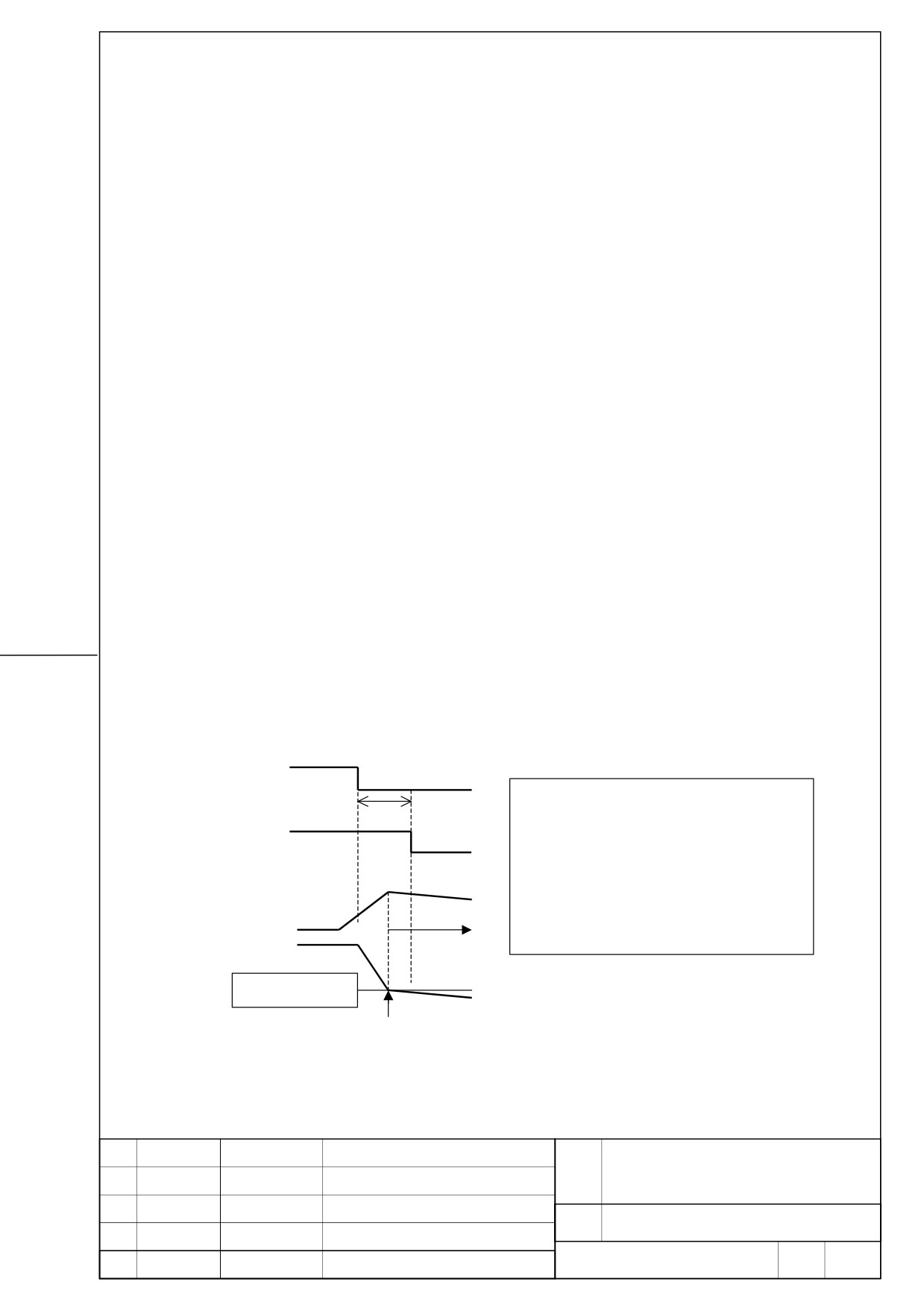
Power failure occurred at the time of motor acceleration. (Please see below.)
βiSV Input Voltage
A power failure detecting signal is outputted
8msec ~ 17msec
from βiSV behind time 8msec~17msec after
power failure occur. When the output power
Power failure
of motor is large by acceleration, DC link
detect signal
voltage falls rapidly. So, even if power failure
Acceleration
is detected, DC link low voltage alarm may be
Motor speed
occurred.
DC link voltage
Low voltage alarm
Of DC link
Alarm occurred
3.
The amplifier is necessary to operate normally at instantaneous power failure for
3msec or less and for this terms the power failure detect signal is not detected.
FANUC SERVO AMPLIFIER
TITLE
βiSV 20/20 DESCRIPTIONS
DRAW.
No.
B-65322EN/02-03
EDIT
DATE
DESIGN
DESCRIPTION
FANUC LTD
Page
15 / 23
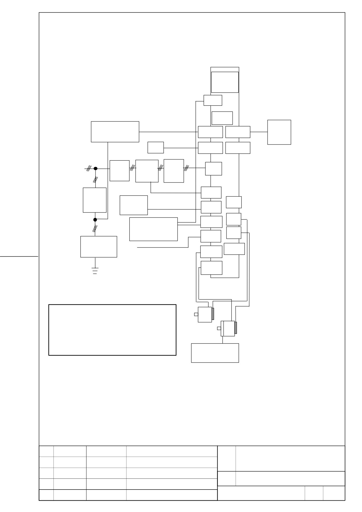
11. Total connection diagram
βiSV
20/20
TB
FUSE
K9
Battery
Stabilized power supply
K11
CXA19B
CXA19A
case
DC24V
Optical cable
NC
COP10A
3 phase
COP10B
200V to 240VAC
Magnetic
AC line
K2
Breaker
CZ4
contactor
filter
K7
5A circuit
CX29
Emergency
breaker
K8
JX5
stop switch
CX30
K4
CXA20
JF1
Separated regenerative
K5
discharge resistor
JF2
CX36
Lighting
Power failure signal
K12
CX5X
surge absorber
CZ5L
CZ5M
K3
K1
CAUTION
1 A circuit breakers, magnetic contactor, and AC line filter
K3
K1
are always required.
2 Use the stabilized 24VDC power supply for the amplifier.
24VDC power supply for the amplifier and 24VDC power
supply for the motor brake cannot be shared.
3 The cabling of CX29 and CX30 of the second and
subsequent amplifiers may be omitted. For details, see
"TOTAL CONNECTION DIAGRAM".
24V powersupply
for motor brake
FANUC SERVO AMPLIFIER
TITLE
βiSV 20/20 DESCRIPTIONS
DRAW.
No.
B-65322EN/02-03
EDIT
DATE
DESIGN
DESCRIPTION
FANUC LTD
Page
16 / 23
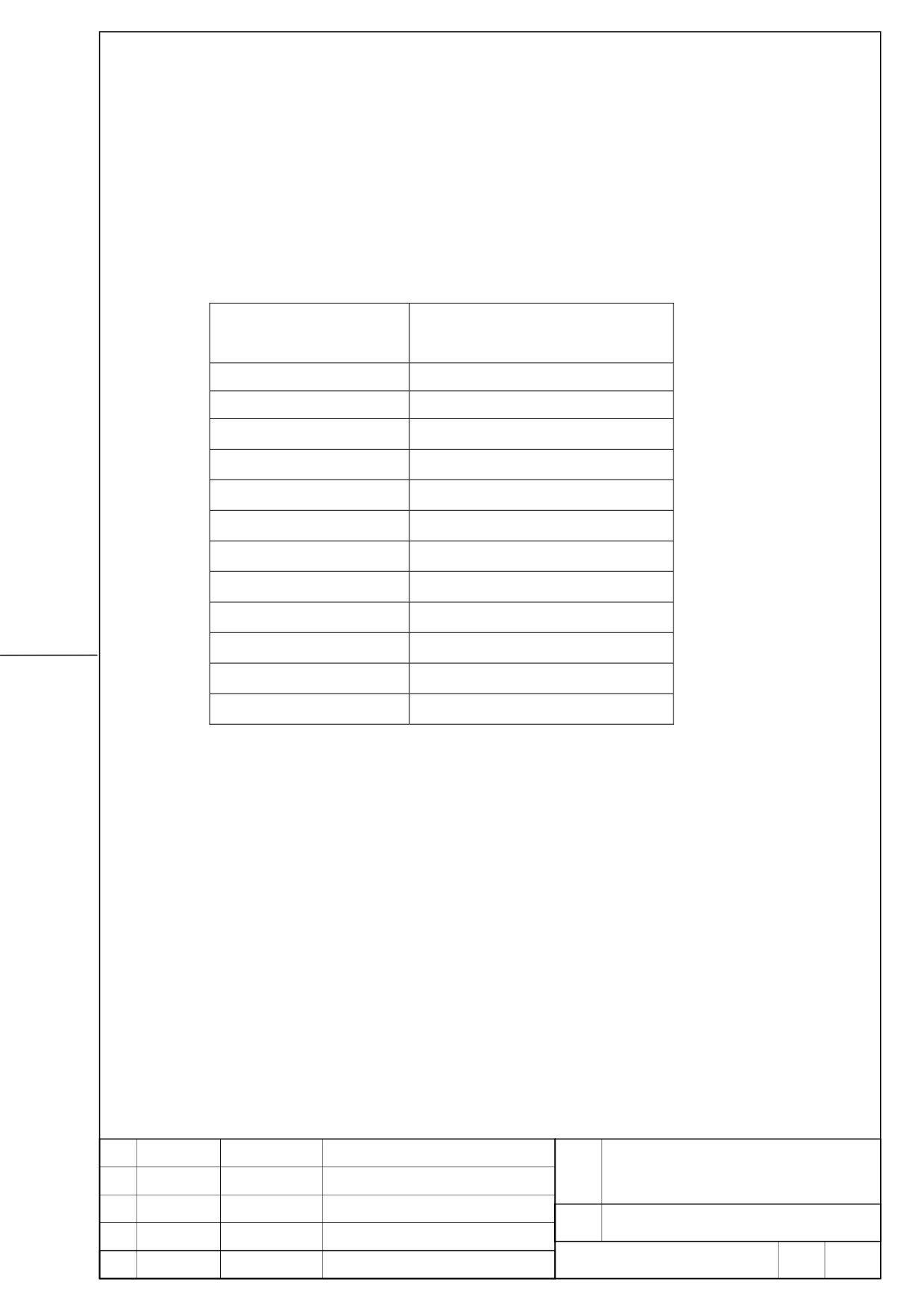
11.1. Connection details
Refer to Section [ I. .SVM ] of B-65322EN/02 for details.
11.2. Details of cable K2 (Refer to B-65322/02EN)
Please select specification of cables in consideration of
following
table.
Refer
to
Section [ I .SVM ] of B-65322EN/02 for details.
Servo motor
Continuous rating current
[Arms]
(Reference value)
βiS 0.4/5000
0.6
βiS 0.5/6000
1.4
βiS 1/6000
2.3
βiS 2/4000
2.2
βiS 4/4000
3.3
βiS 8/3000
5.4
βiS 12/2000
6.3
αiF 1/5000
2.2
αiF 2/5000
3.3
αiS 2/5000
3.3
αiS 2/6000
4.5
αiS 4/5000
4.5
FANUC SERVO AMPLIFIER
TITLE
βiSV 20/20 DESCRIPTIONS
DRAW.
No.
B-65322EN/02-03
EDIT
DATE
DESIGN
DESCRIPTION
FANUC LTD
Page
17 / 23
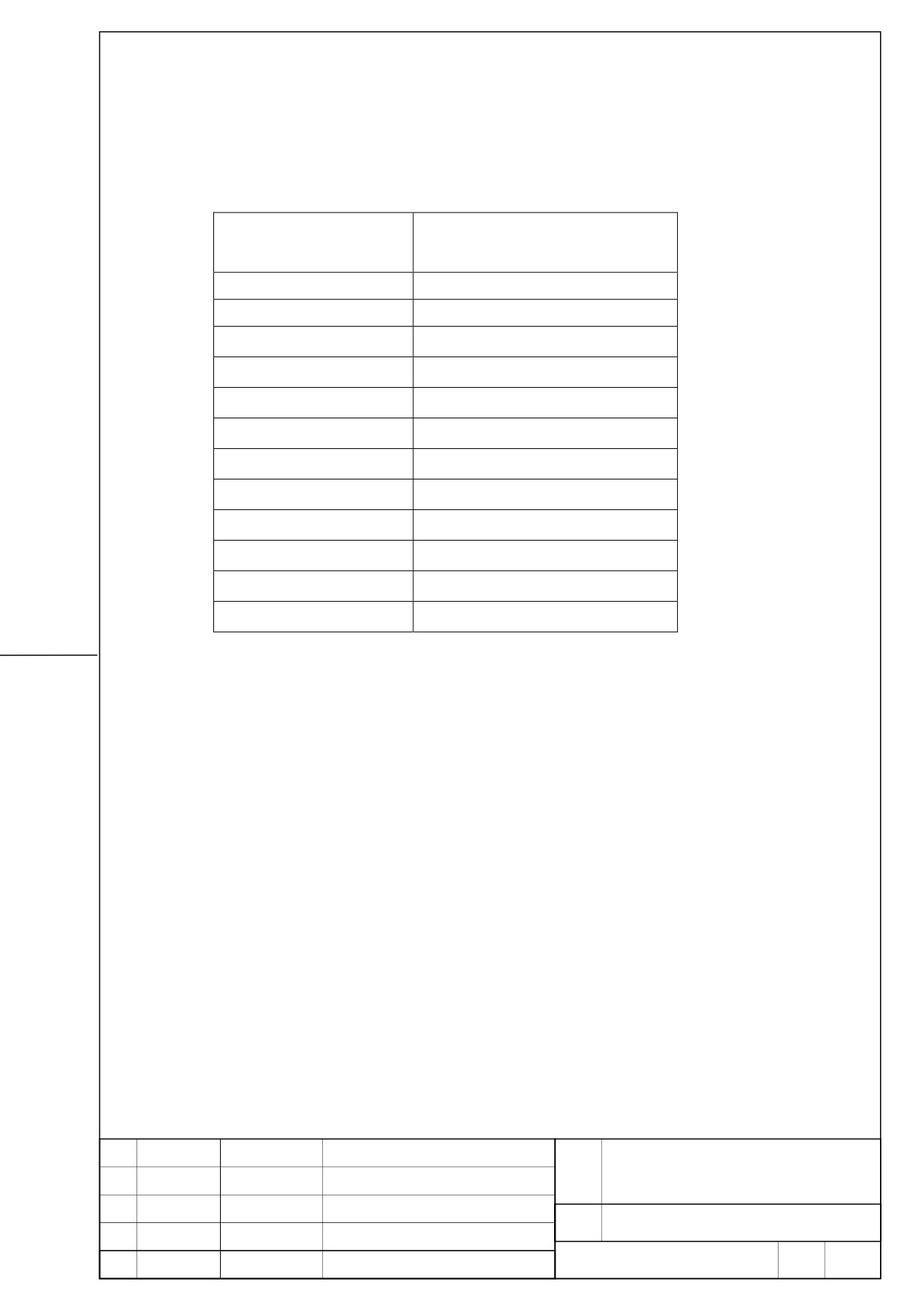
11.3. Details of cable K3 (Refer to B-65322/02EN)
Please select specification of cables in consideration of
following
table.
Refer
to
Section [ I.SVM ] of B-65322EN/02 for details.
Servo motor
Continuous rating current
[Arms]
(Reference value)
3.6
βiS 0.4/5000
3.0
βiS 0.5/6000
βiS 1/6000
2.7
βiS 2/4000
3.2
βiS 4/4000
4.7
βiS 8/3000
6.0
βiS 12/2000
6.5
αiF 1/5000
2.7
αiF 2/5000
3.5
αiS 2/5000
3.3
αiS 2/6000
4.1
αiS 4/5000
4.6
FANUC SERVO AMPLIFIER
TITLE
βiSV 20/20 DESCRIPTIONS
DRAW.
No.
B-65322EN/02-03
EDIT
DATE
DESIGN
DESCRIPTION
FANUC LTD
Page
18 / 23
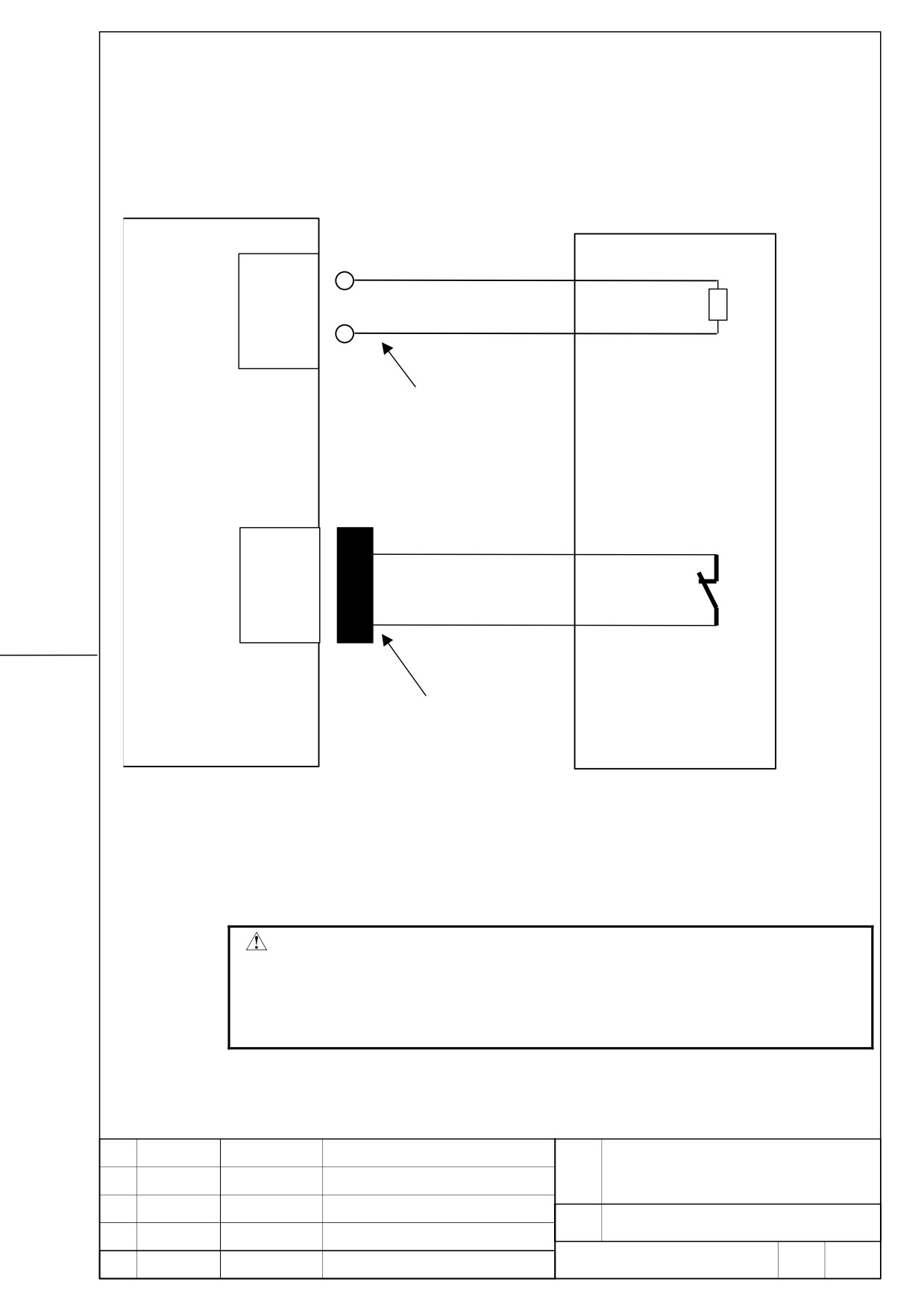
11.4. Details of cable K4 (Refer to B-65322/02EN)
In case of using regenerative discharge resistor
(a) A06B-6130-H404
Regenerative
βiSV 20/20
discharge resistor
TB
DCP
DCP
DCP
DCC
DCC
DCC
Resistor
Crimp terminal: 1.25-6
CXA20
1
TH1
2
TH2
Thermostat
D-2000 series
Housing: 1-1318120-3
Contact: 1318107-1
Applicable wire: 0.30 to 0.85mm2
Manufacture: Tyco Electronics AMP
For connection tools, see subsection 9.2.3. of [I.SVM ] for B-65322EN/02
WARNING
z Do not short between terminal “DCP” and terminal “DCC”.
z Do not connect this terminal “TB” to terminal “TB1(DCP/DCN)” of
servo amplifier αi series.
Servo amplifier may be broken in case of above incorrect connection.
FANUC SERVO AMPLIFIER
TITLE
βiSV 20/20 DESCRIPTIONS
DRAW.
No.
B-65322EN/02-03
EDIT
DATE
DESIGN
DESCRIPTION
FANUC LTD
Page
19 / 23
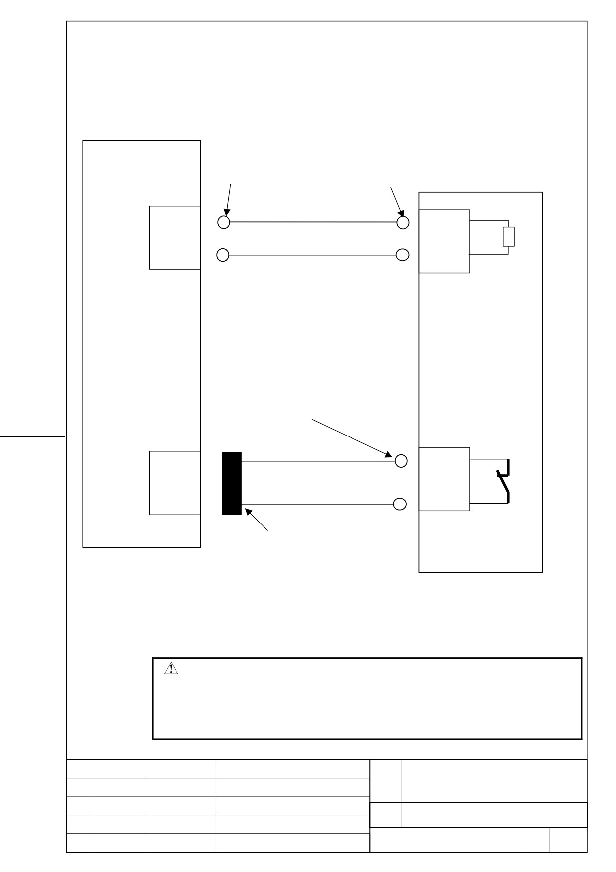
(b) A06B-6089-H500
Cable specification:
Two-conductor polyvinyl heavy-duty power cable
JIS C 3312
βiSV 20/20
Conductor size of 3.5mm2
Regenerative
Crimp terminal
Crimp terminal
discharge resistor
5.5-6
5.5-4
TB
DCP
DCP
DCP
DCC
DCC
DCC
Resistor
Cable specification:
Two-conductor polyvinyl heavy-duty power cable
JIS C 3312
Conductor size of 0.75mm2
Crimp terminal: 1.25-4
CXA20
1
TH1
2
TH2
Thermostat
D-2000series
Housing: 1-1318120-3
Contact: 1318107-1
Applicable wire: 0.3mm2 to 0.85mm2
Manufacture: Tyco Electronics AMP
For connection tools, see subsection 9.2.3. of [I.SVM ] for B-65322EN/02
WARNING
z Do not short between terminal “DCP” and terminal “DCC”.
z Do not connect this terminal “TB” to terminal “TB1(DCP/DCN)” of
servo amplifier αi series.
Servo amplifier may be broken in case of above incorrect connection.
FANUC SERVO AMPLIFIER
TITLE
βiSV 20/20 DESCRIPTIONS
DRAW.
No.
B-65322EN/02-03
EDIT
DATE
DESIGN
DESCRIPTION
FANUC LTD
Page
20 / 23
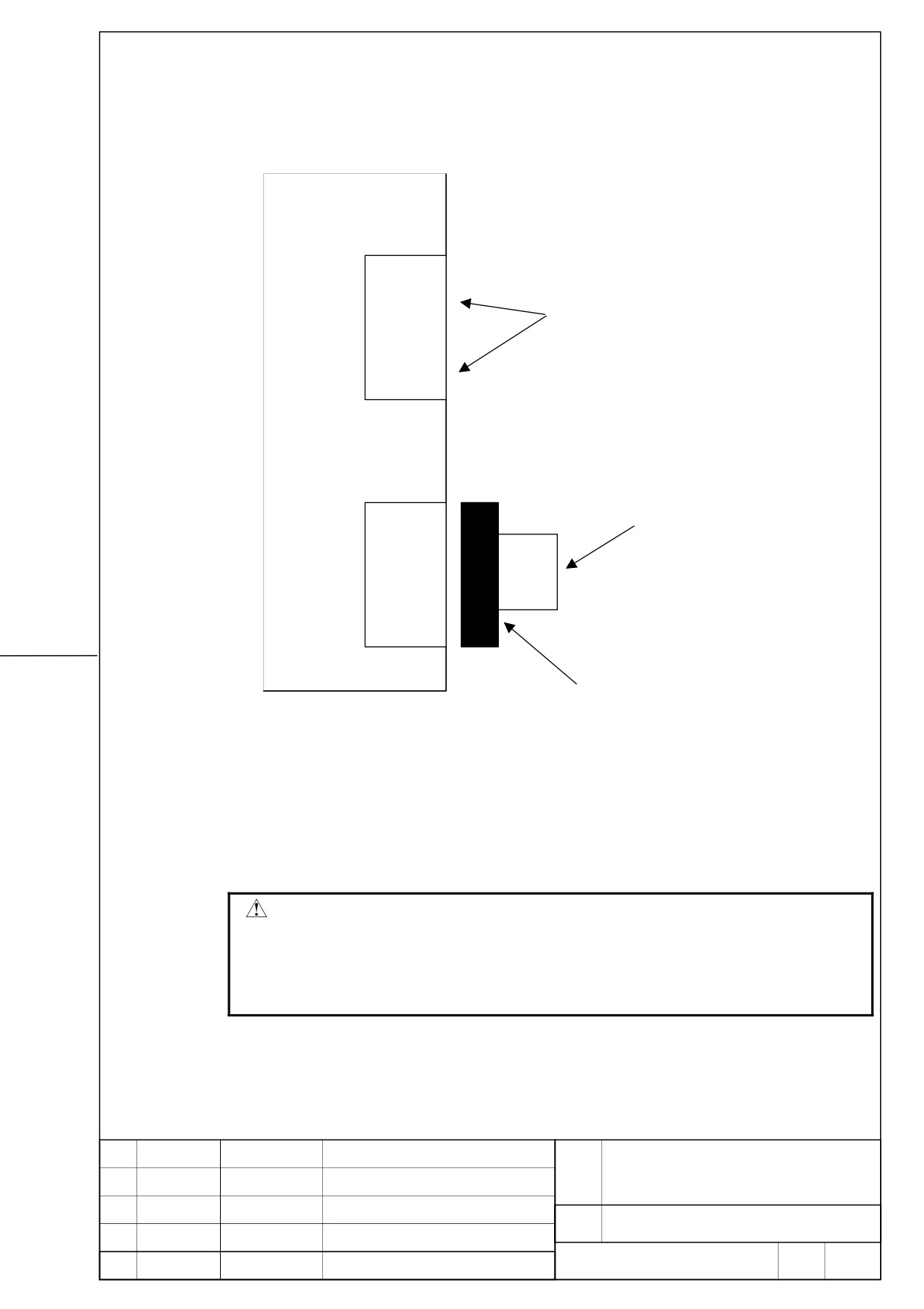
(c) In case of not using regenerative discharge resistor
βiSV 20/20
TB
DCP
Keep these pins unconnected.
(Do not install a jumper between pins.)
DCC
CXA20
Install jumper between pins.
1
2
D-2000 series
Housing: 1-1318120-3
Contact: 1318107-1
Applicable wire 0.30 to 0.85mm2
Manufacture: Tyco Electronics AMP
For connection tools, see subsection 9.2.3. of [I.SVM ] for B-65322EN/02
WARNING
z Do not short between terminal “DCP” and terminal “DCC”.
z Do not connect this terminal “TB” to terminal “TB1(DCP/DCN)” of
servo amplifier αi series.
Servo amplifier may be broken in case of above incorrect connection.
FANUC SERVO AMPLIFIER
TITLE
βiSV 20/20 DESCRIPTIONS
DRAW.
No.
B-65322EN/02-03
EDIT
DATE
DESIGN
DESCRIPTION
FANUC LTD
Page
21 / 23
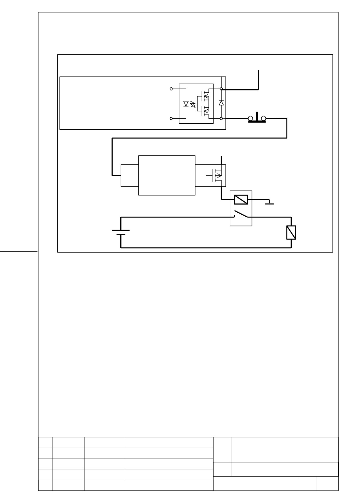
11.5. Details of cable K12
24V
CX36
βiSV 20/20
2
Power failure detect signal output
Normal: ON
*ESP
Power failure detection: OFF
3
24V
PMC
DI
DO
*ESP
Relay for mechanical brake coil
0V
Mechanical brake coil
CX36 specification (Rated output)
Output voltage:
30V Max.
Output current :
200mA Max.
FANUC SERVO AMPLIFIER
TITLE
βiSV 20/20 DESCRIPTIONS
DRAW.
No.
B-65322EN/02-03
EDIT
DATE
DESIGN
DESCRIPTION
FANUC LTD
Page
22 / 23
12. Heat disspaton
The amount of heat dissipation depends on the current that flows through the servo amplifier
and servo motor. For the current that flows through a servo motor, reference the continuous
rated current of each servo motor. (For the continuous rated current of each servo motor,
refer to the servo motor descriptions.) As the current that flows through a servo motor, the
root-mean-square value of the current that flows through an actual servo motor on a machine
can be used. The amount of heat dissipation indicated below assumes the use of HRV2.
(1) Total amount of heat dissipation
The total amount of heat dissipation is calculated
according to the following expression:
Total amount of heat dissipation= a + Ka1 × b1
a: Amount of heat dissipation determined by the βiSV
[W]
Ka1: Coefficient determined by the βiSV [W/Arms]
b1: Current flowing through the servo motor [Arms]
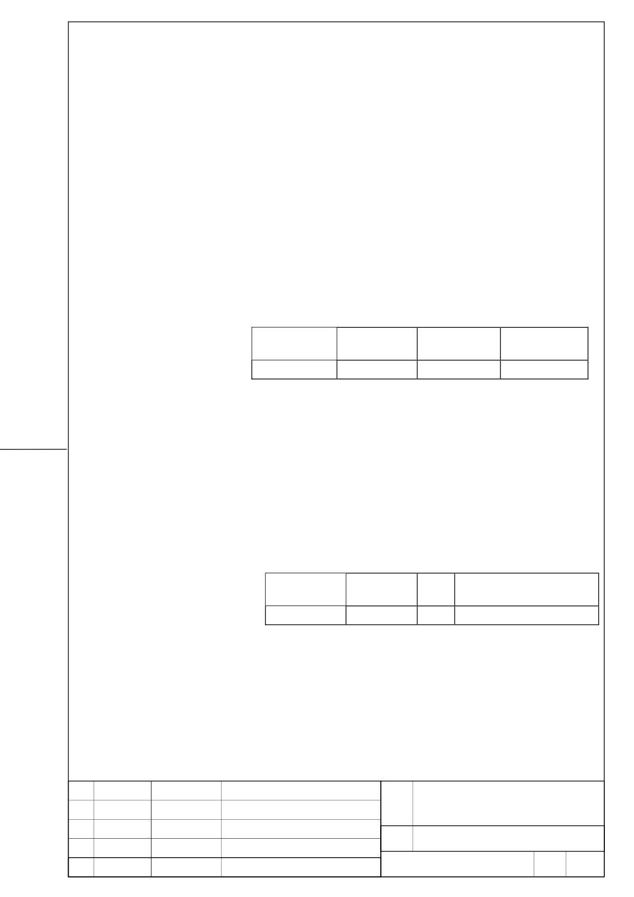
Total amount of heat dissipation
A
K
Name
Specification
[W]
[W/Arms]
βiSV 20/20
H201
20
Ka1: 12.6
(2) Residual amount of heat in the cabinet
By placing the heat sink section outside the cabinet, the
residual amount of heat in the cabinet can be calculated
according to the expression below.
Residual amount of heat in the cabinet= a + Kb1 × b1
a: Amount of heat dissipation determined by the βiSV
[W]
Kb1: Coefficient determined by the βiSV [W/Arms]
b1: Current flowing through the servo motor [Arms]
Residual amount of heat in the cabinet
a
K
Name
Specification
[W]
[W/Arms]
βiSV 20/20
H201
20
Ka1: 12.6
FANUC SERVO AMPLIFIER
TITLE
βiSV 20/20 DESCRIPTIONS
DRAW.
No.
B-65322EN/02-03
EDIT
DATE
DESIGN
DESCRIPTION
FANUC LTD
Page
23 / 23