FANUC Series 0i-MODEL D, Series 0i Mate-MODEL D. For Machining Center System USER’S MANUAL - page 8
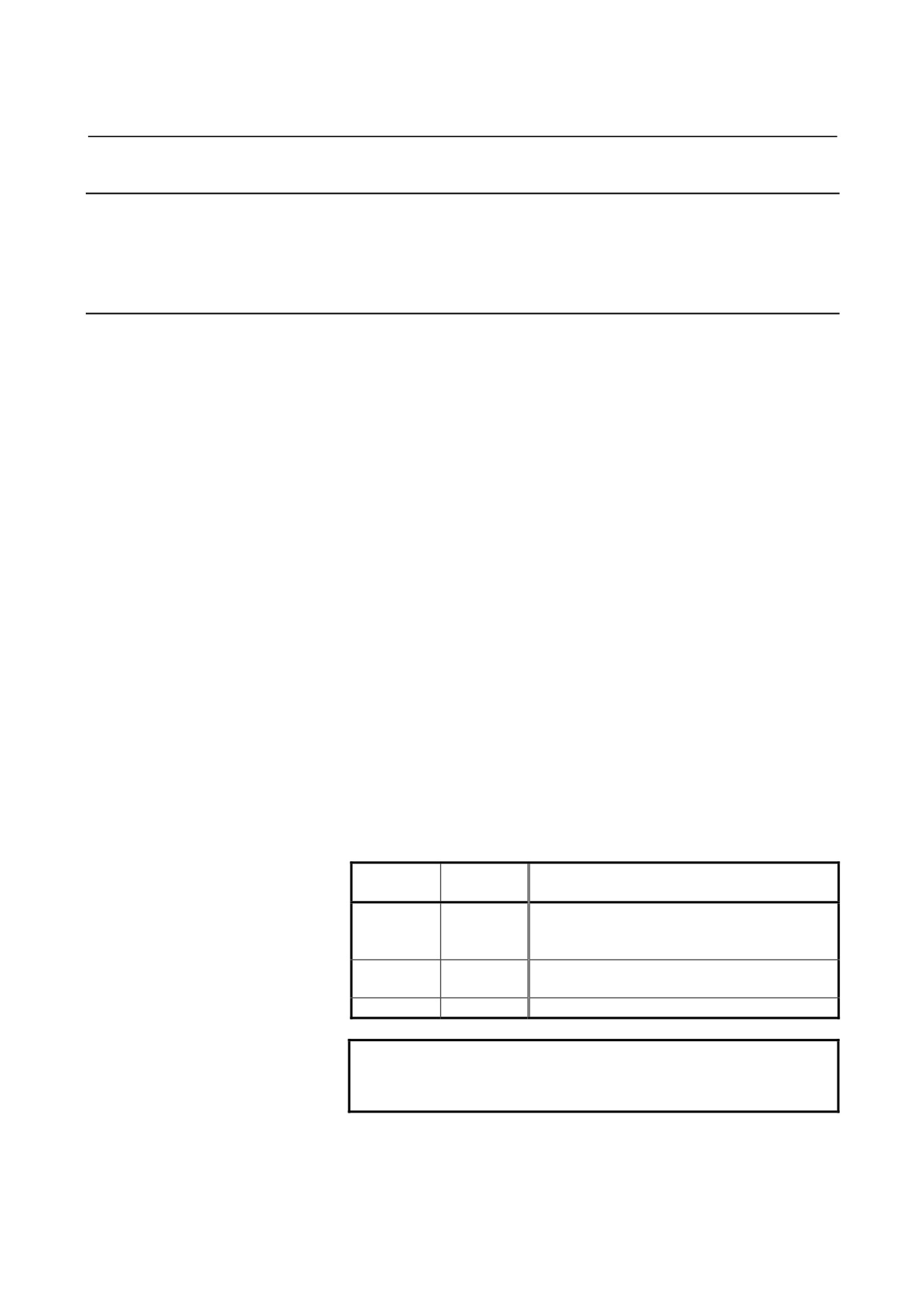
6.COMPENSATION FUNCTION
PROGRAMMING
B-64304EN-2/01
6.6.6
Interference Check
Tool overcutting is called interference. The interference check
function checks for tool overcutting in advance. However, all
interference cannot be checked by this function. The interference
check is performed even if overcutting does not occur.
Explanation
- Condition under which an interference check is possible
To perform an interference check, it is necessary to read at least three
blocks with tool movement. If, therefore, three or more blocks with
tool movement cannot be read in offset mode because blocks without
tool movement, such as independent auxiliary function and dwell, are
specified in succession, excessive or insufficient cutting may occur
because an interference check fails. Assuming the number of blocks
to read in offset mode, which is determined by parameter (No. 19625),
to be N and the number of commands in those N blocks without tool
movement that have been read to be M, the condition under which an
interference check is possible is
(N - 3) ≥ M.
For example, if the maximum number of blocks to read in offset mode
is 8, an interference check is possible even if up to five blocks without
tool movement are specified. In this case, three adjacent blocks can
be checked for interference, but any subsequent interference that may
occur cannot be detected.
- Interference check method
Two interference check methods are available, direction check and
circular angle check. Parameter CNC (No. 5008#1) and parameter
CNV (No. 5008#3) are used to specify whether to enable these
methods.
Parameter
Parameter
Operation
CNV
CNC
An interference check is enabled, and a
0
0
direction check and a circular angle check can
be performed.
An interference check is enabled, and only a
0
1
circular angle check is performed.
1
-
An interference check is disabled.
NOTE
There are no settings for performing a direction
check only.
- 196 -
B-64304EN-2/01
PROGRAMMING
6.COMPENSATION FUNCTION
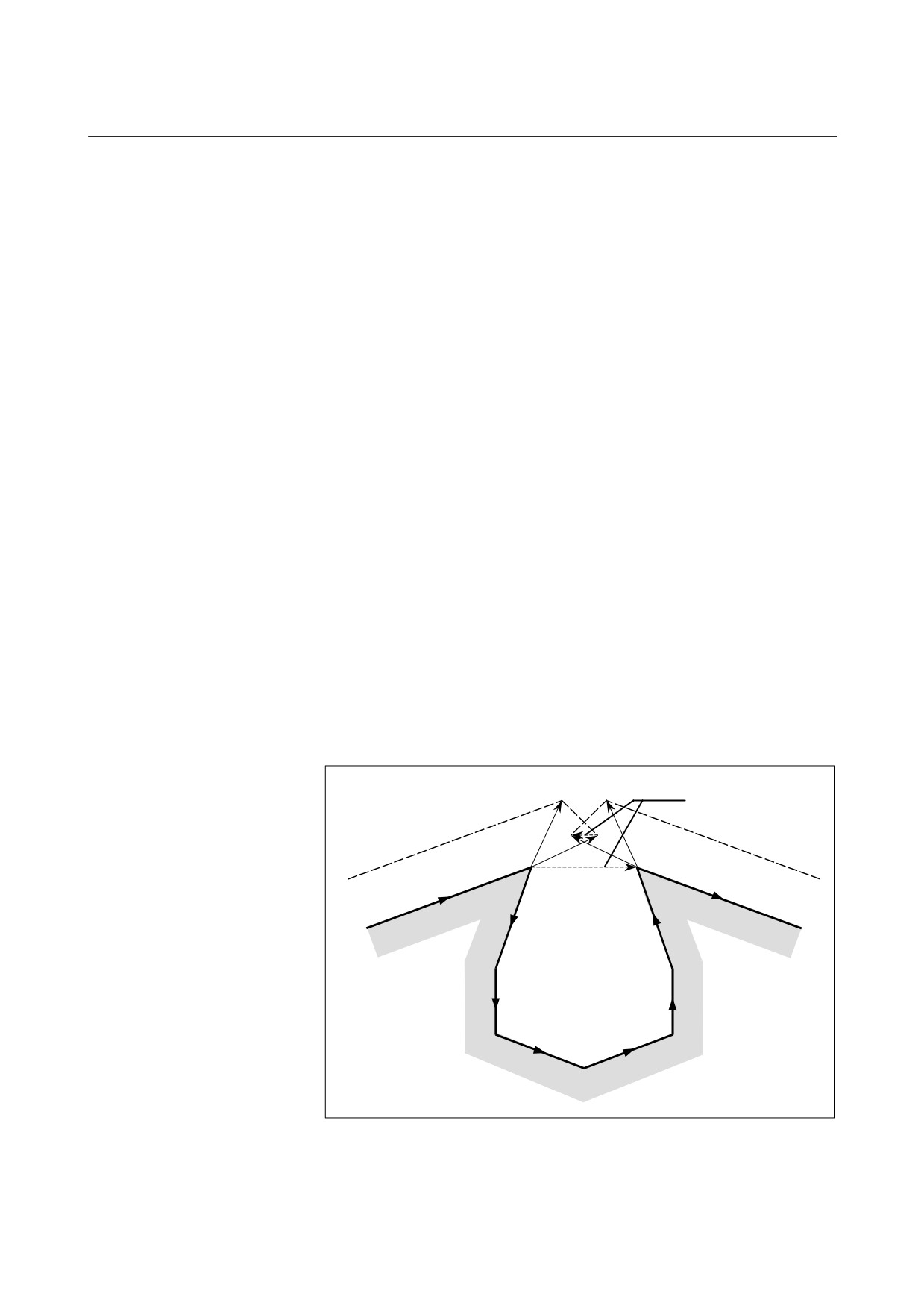
- Interference reference <1> (direction check)
Assuming the number of blocks to read during cutter compensation to
be N, a check is first performed on the compensation vector group
calculated in
(block
1 - block 2) to be output this time and the
compensation vector group calculated in (block N-1 - block N); if they
intersect, they are judged to interfere. If no interference is found, a
check is performed sequentially in the direction toward the
compensation vector group to be output this time, as follows:
(Block 1 - block 2) and (block N-2 - block N-1)
(Block 1 - block 2) and (block N-3 - block N-2)
:
:
(Block 1 - block 2) and (block 2 - block 3)
Even if multiple number of compensation vector groups are generated,
a check is performed on all pairs.
The judgment method is as follows:
For a check on the
compensation vector group in (block 1 - block 2) and those in (block
N-1 - block N), the direction vector from the specified (end point of
block 1) to the (end point of block N-1) is compared with the direction
vector from the (point resulting from adding the compensation vector
to be checked to the end of block 1) to the (point resulting from
adding the compensation vector to be checked to the end of block
N-1), and if the direction is 90o or greater or 270o or less, they are
judged to intersect and interfere. This is called a direction check.
Example of interference standard <1>
(If the block 1 end-point vector intersects with the block 7 end-point
vector)
The direction differs by
180°.
Tool center path
Programmed path
Block 2
Block 7
Block 1
Block 8
Block 3
Block 6
Block 4
Block 5
- 197 -
6.COMPENSATION FUNCTION
PROGRAMMING
B-64304EN-2/01
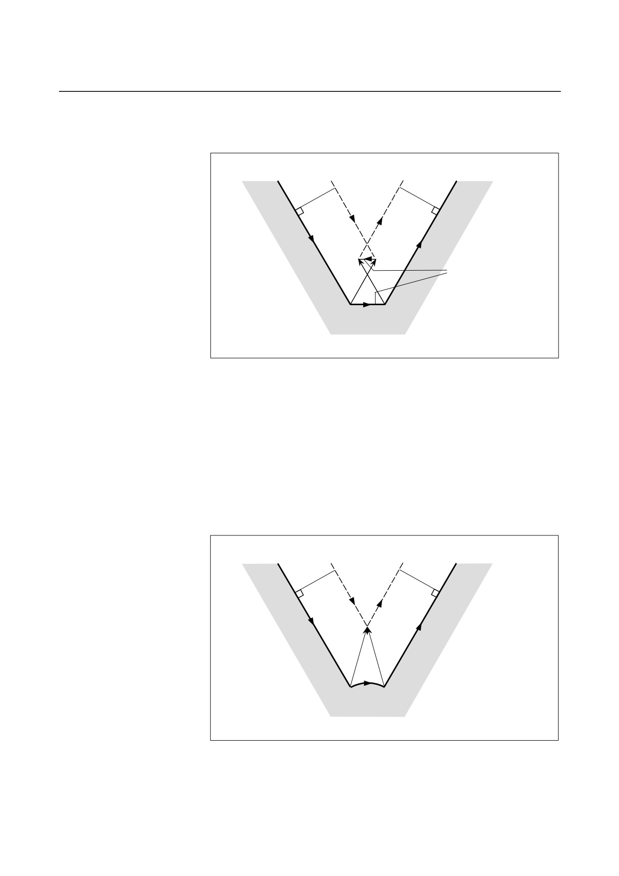
Example of interference standard <1>
(If the block 1 end-point vector intersects with the block 2 end-point
vector)
Programmed path
Tool center path
Block 1
The directions of
these two paths are
different (180°).
Block 2
- Interference reference <2> (circular angle check)
In a check on three adjacent blocks, that is, a check on the
compensation vector group calculated on (block 1 - block 2) and the
compensation vector group calculated on (block 2 - block 3), if block
2 is circular, a check is performed on the circular angle between the
start and end points of the programmed path and the circular angle of
the start and end point of the post-compensation path, in addition to
direction check <1>. If the difference is 180o or greater, the blocks
are judged to interfere. This is called a circular angle check.
Example of <2> (if block 2 is circular and the start point of the
post-compensation arc coincide with the end point)
Tool center path
Programmed path
Block 3
Block 1
Programmed path
Block 2
- 198 -
B-64304EN-2/01
PROGRAMMING
6.COMPENSATION FUNCTION
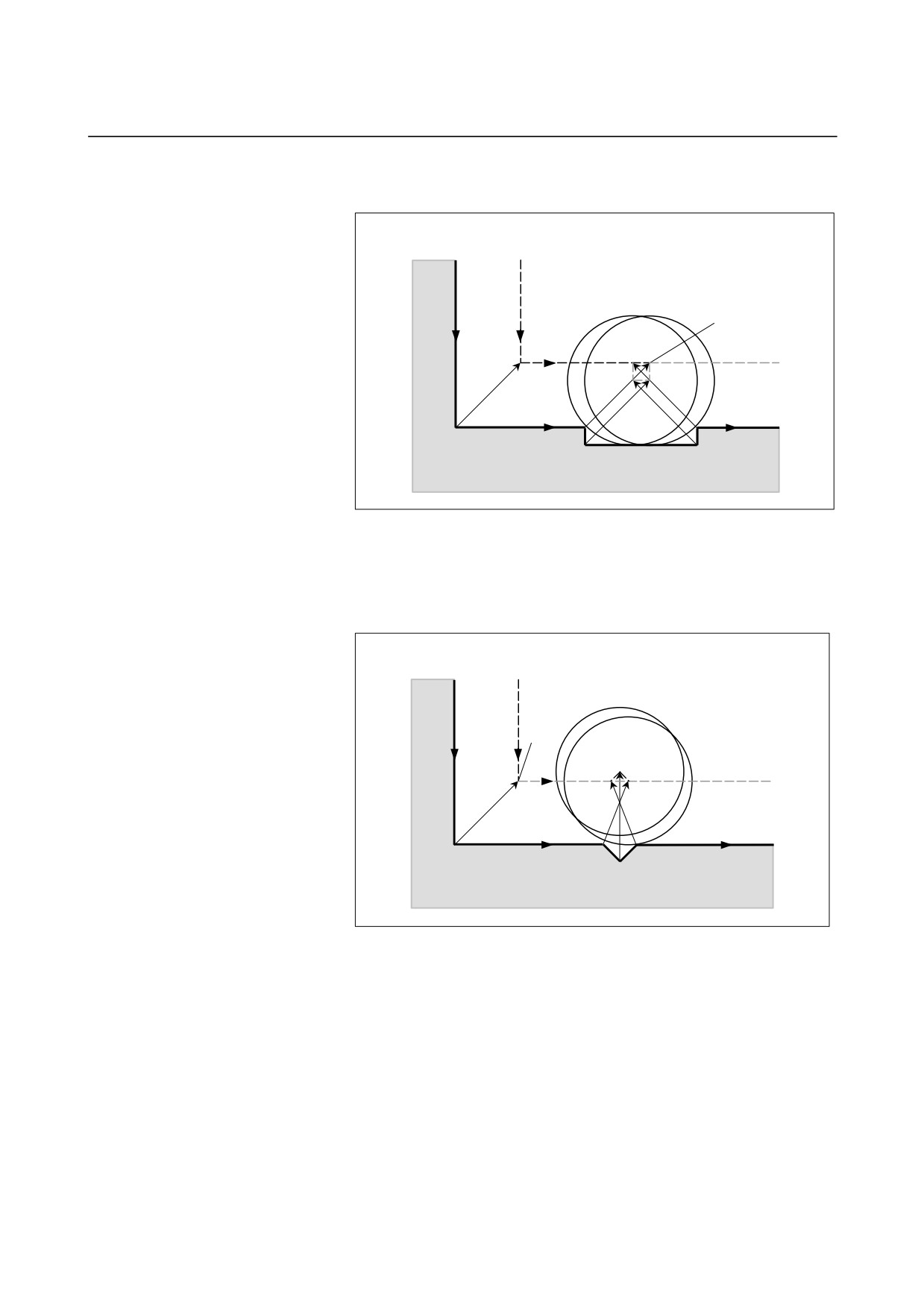
- When interference is assumed although actual interference does not occur
<1> Depression which is smaller than the cutter compensation value
Programmed
path
Tool center path
Stopped
A
C
B
There is no actual interference, but since the direction
programmed in block B is opposite to that of the path after the
cutter compensation, the tool stops and an alarm is displayed.
<2> Groove which is smaller than the cutter compensation value
Programmed
path
Tool center path
Stopped
A
B
C
Like <1>, an alarm is displayed because of the interference as the
direction is reverse in block B.
- 199 -
6.COMPENSATION FUNCTION
PROGRAMMING
B-64304EN-2/01
6.6.6.1 Operation to be performed if an interference is judged to
occur
The operation to be performed if an interference check judges that an
interference (due to overcutting) occurs can be either of the following
two, depending on the setting of parameter CAV (No. 19607#5).
Parameter
Function
Operation
CAV
An alarm stop occurs before the
Interference check
0
execution of the block in which
alarm function
overcutting (interference) occurs.
The tool path is changed so that
Interference check
1
overcutting (interference) does not
avoidance function
occur, and processing continues.
6.6.6.2 Interference check alarm function
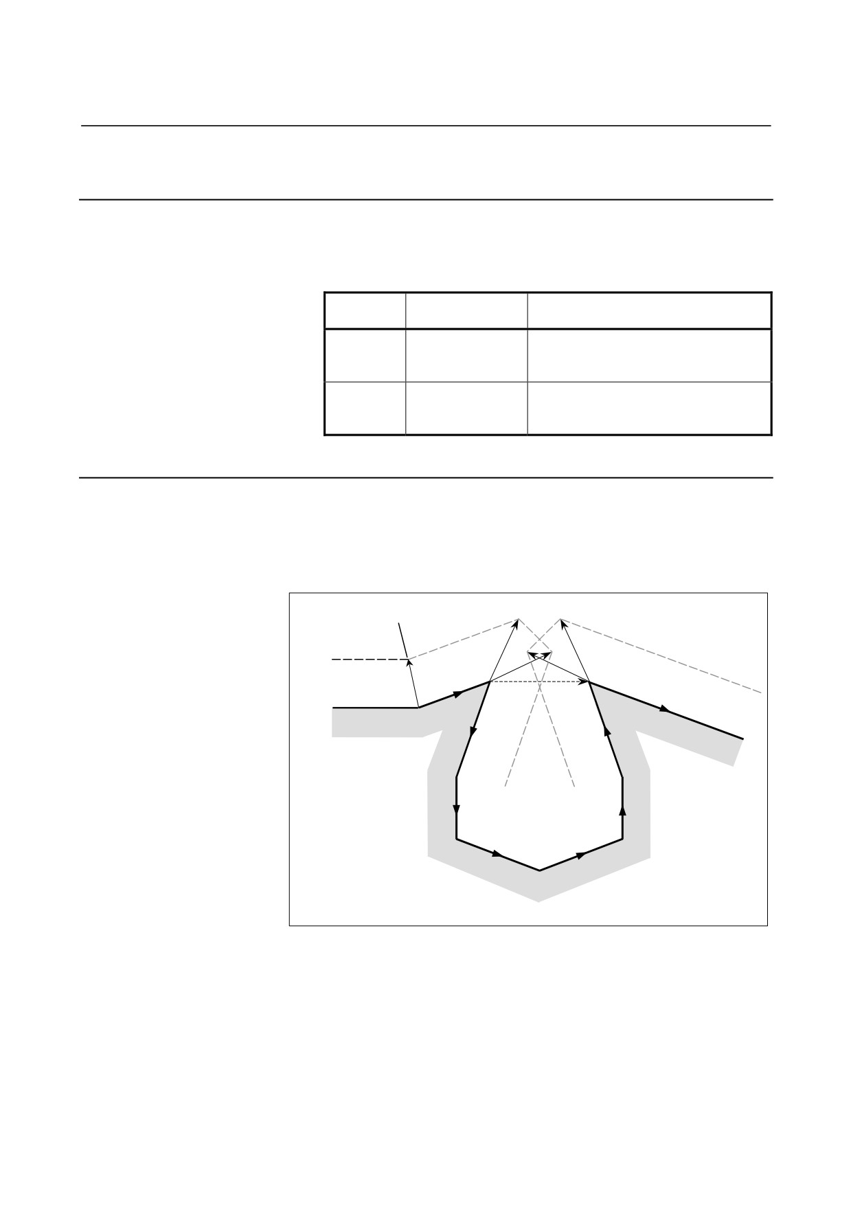
- Interference other than those between adjacent three blocks
If the end-point vector of block 1 and the end-point vector of block 7
are judged to interfere as shown in the figure, an alarm will occur
before the execution of block 1 so that the tool stops. In this case,
the vectors will not be erased.
Stopped
Tool center path
Block 1
Block 8
Programmed path
Block 2
Block 7
Block 3
Block 6
Block 4
Block 5
- 200 -
B-64304EN-2/01
PROGRAMMING
6.COMPENSATION FUNCTION
- Interference between adjacent three blocks
If an interference is judged to occur between adjacent three blocks, the
interfering vector, as well as any vectors existing inside of it, is erased,
and a path is created to connect the remaining vectors. In the
Example shown in the figure below, V2 and V5 interfere, so that V2
and V5 are erased, so are V3 and V4, which are inside of them, and V1
is connected to V6. The operation during this time is linear
interpolation.
V6
V1
V2
V5
V4
V3
Tool center path
Programmed path
If, after vector erasure, the last single vector still interferes, or if there
is only one vector at the beginning and it interferes, an alarm will
occur immediately after the start of the previous block (end point for a
single block) and the tool stops. In the Example shown in the figure
below, V2 and V3 interfere, but, even after erasure, an alarm will occur
because the final vectors V1 and V4 interfere.
Stopped
Tool center path
Programmed path
V4
V1
V3
V2
- 201 -

6.COMPENSATION FUNCTION
PROGRAMMING
B-64304EN-2/01
6.6.6.3 Interference check avoidance function
Overview
If a command is specified which satisfies the condition under which
the interference check alarm function generates an interference alarm,
this function suppresses the generation of the interference alarm, but
causes a new compensation vector to be calculated as a path for
avoiding interference, thereby continuing machining. For the path
for avoiding interference, insufficient cutting occurs in comparison
with the programmed path. In addition, depending on the specified
figure, no path for avoiding interference can be determined or the path
for avoiding interference may be judged dangerous. In such a case,
an alarm stop will occur. For this reason, it is not always possible to
avoid interference for all commands.
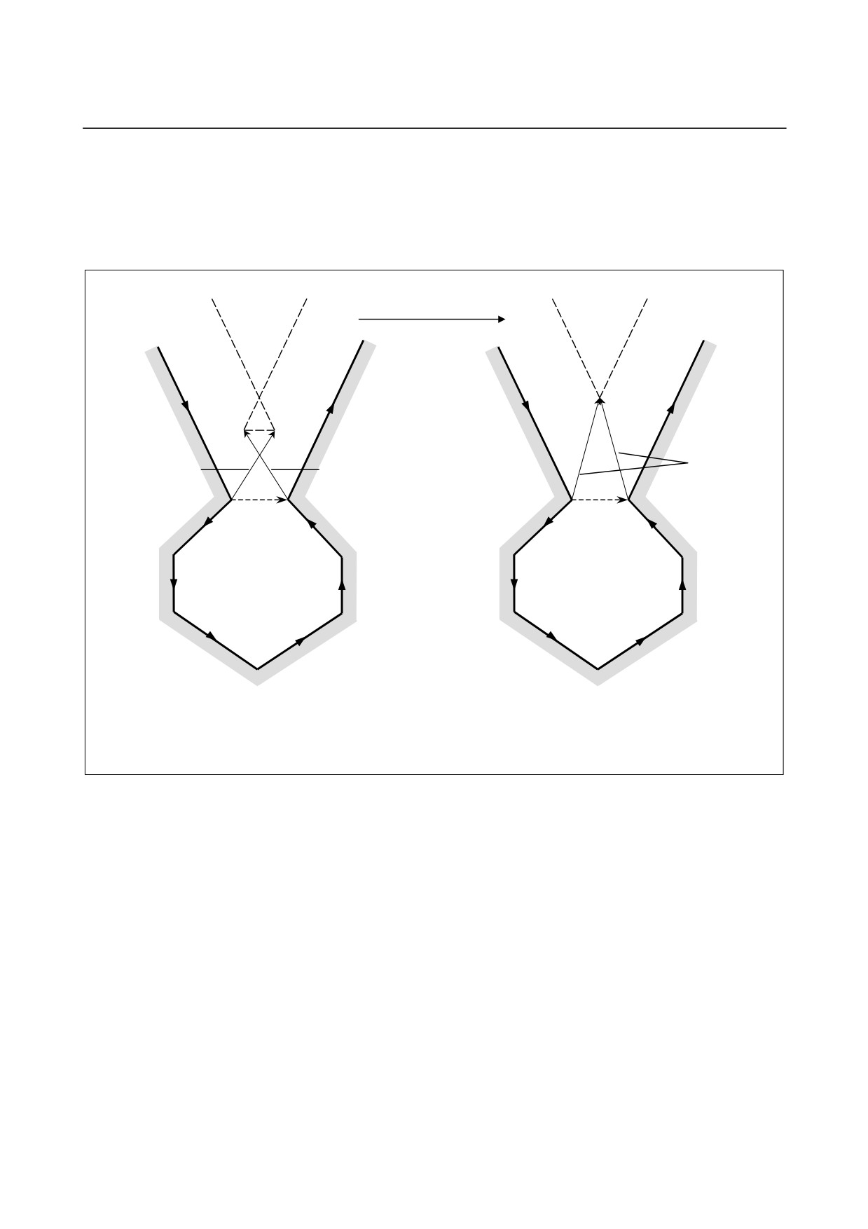
- Interference avoidance method
Let us consider a case in which an interference occurs between the
compensation vector between
(block
1
- block
2) and the
compensation vector between (block N-1 - block N). The direction
vector from the end point of block 1 to the end point of block N-1 is
called a gap vector. At this time, a post-compensation intersection
vector between
(block
1 - gap vector) and a post-compensation
intersection vector between (gap vector - block N) is determined, and
a path connecting them is created.
Post-compensation intersection vector
Post-compensation intersection vector
between gap vector and block 8
between block 1 and gap vector
Movement o f block 7
Post-compensation
path
Gap vector
Block 1
Block 8
Block 2
Block 7
Programmed path
Block 3
Block 6
Block 4
Block 5
In this case, the post-compensation end points of blocks 2 to 6 coincide with the end
point of block 1. Thus, after compensation, blocks 2 to 6 will be blocks without tool
movement.
- 202 -
B-64304EN-2/01
PROGRAMMING
6.COMPENSATION FUNCTION
If the post-compensation intersection vector of (block 1 - gap vector)
and the post-compensation intersection vector of (gap vector - block
N) further intersect, vector erasure is first performed in the same way
as in "Interference between adjacent three blocks". If the last vectors
that remains still intersects, the post-compensation intersection vector
of (block 1 - block N) is re-calculated.
Post-compensation path
Re-calculation
Programmed path
Block 1
Block 8
Block 1
Block 8
Post-
Post-compensation
compensation
Post-compensation
intersection
intersection vector
intersection between
between block 1 and
vector between
gap vector and block 8
block 1 and
gap vector
block 8
Block 2
Gap vector
Block 7
Block 2
Block 7
Block 3
Block 3
Block 6
Block 6
Block 4
Block 4
Block 5
Block 5
In this case, the post-compensation end points of blocks 2 to 7
coincide with the end point of block 1. Thus, after compensation,
blocks 2 to 7 will be blocks without tool movement.
- 203 -
6.COMPENSATION FUNCTION
PROGRAMMING
B-64304EN-2/01
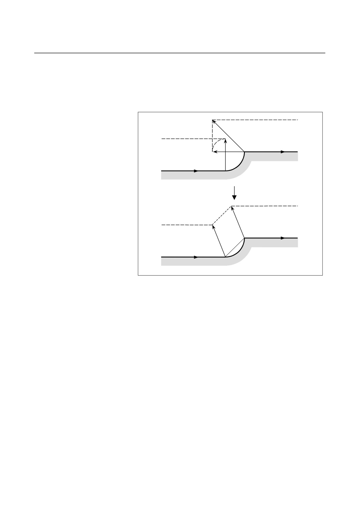
If the cutter compensation value is greater than the radius of the
specified arc as shown in the figure below, and a command is
specified which results in compensation with respect to the inside of
the arc, interference is avoided by performing intersection calculation
with an arc command being assumed a linear one. In this case,
avoided vectors are connected with linear interpolation.
Post-compensation path
Programmed path
- 204 -
B-64304EN-2/01
PROGRAMMING
6.COMPENSATION FUNCTION
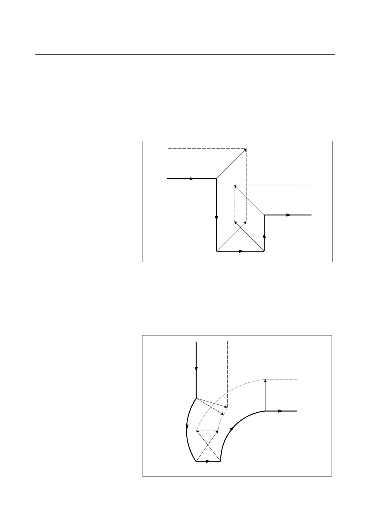
- If no interference avoidance vector exists
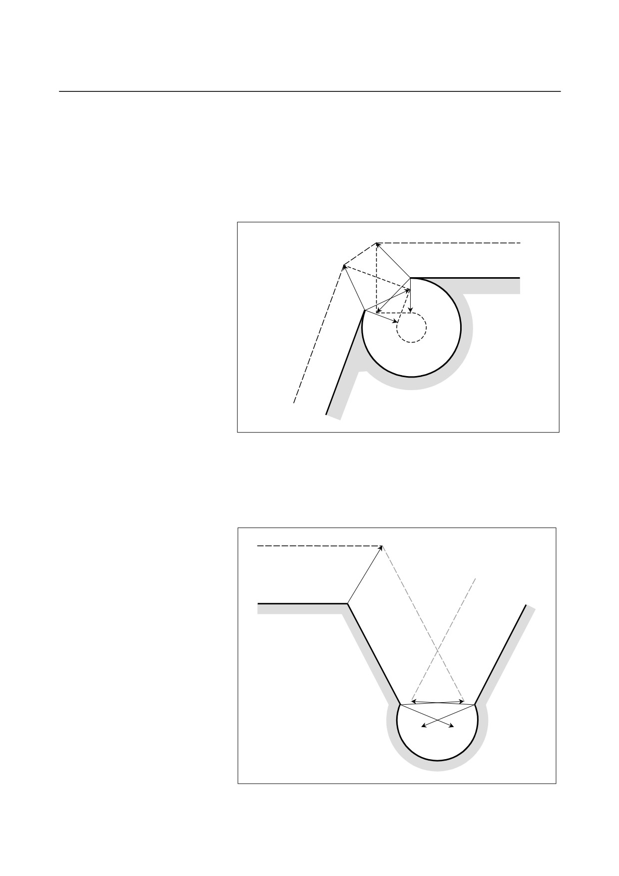
If the parallel pocket shown in the figure is to be machined, the
end-point vector of block 1 and the end-point vector of block 2 are
judged to interfere, and an attempt is made to calculate, as an
interference avoidance vector, the intersection vector of the
post-compensation path of block 1 and the post-compensation path of
block 3. In this case, because blocks 1 and 3 are parallel to each
other, no intersection exists. In this case, an alarm will occur
immediately before block 1 and the tool will stop.
Stopped
Tool center path
Programmed path
Block 1
Block 3
Block 2
If the circular pocket shown in the figure is to be machined, the
end-point vector of block 1 and the end-point vector of block 2 are
judged to interfere, and an attempt is made to calculate, as an
interference avoidance vector, the intersection vector of the
post-compensation path of block 1 and the post-compensation path of
block
3.
In this case, because blocks
1 and 3 are circular, no
post-compensation intersection exists. In this case, an alarm will
occur immediately before block 1 and the tool will stop, as in the
previous example.
Programmed path
Tool center path
Stopped
Block 1
Block 3
Block 2
- 205 -
6.COMPENSATION FUNCTION
PROGRAMMING
B-64304EN-2/01
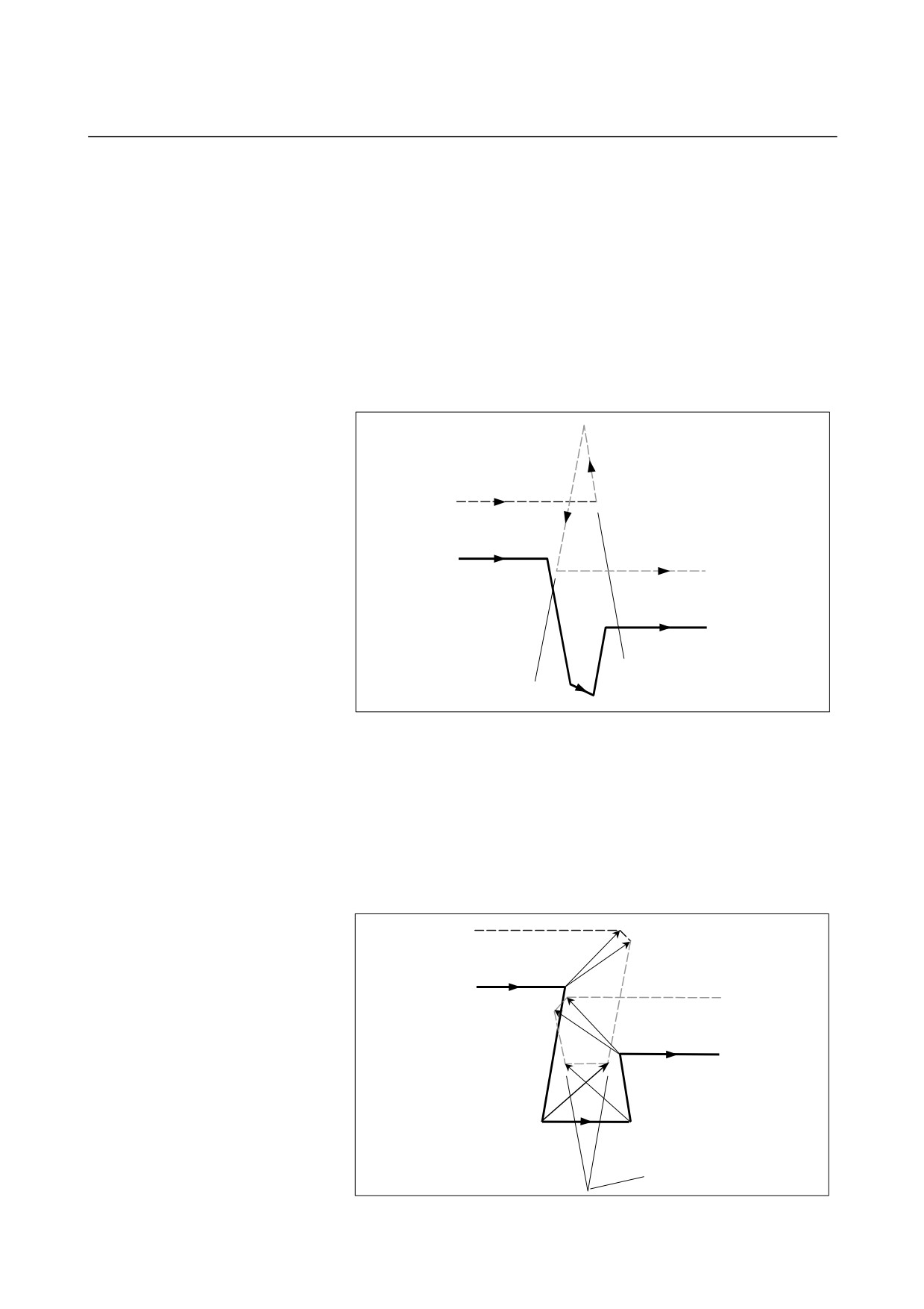
- If it is judged dangerous to avoid interference
If the acute-angle pocket shown in the figure is to be machined, the
end-point vector of block 1 and the end-point vector of block 2 are
judged to interfere, and an attempt is made to calculate, as an
interference avoidance vector, the intersection vector of the
post-compensation path of block 1 and the post-compensation path of
block 3. In this case, the movement direction of the post-avoidance
path extremely differs from the previously specified direction. If the
post-avoidance path extremely differs from that of the original
command (90° or greater or 270° or less), interference avoidance
operation is judged dangerous; an alarm will occur immediately before
block 1 and the tool will stop.
Post-compensation intersection of
blocks 1 and 3
Tool center path
Stopped
Programmed path
Block 1
Block 3
Block 2
If a pocket in which the bottom is wider than the top, such as that
shown in the figure, is to be machined, the end-point vector of block 1
and the end-point vector of block 2 are judged to interfere, and an
attempt is made to calculate, as an interference avoidance vector, the
intersection vector of the post-compensation path of block 1 and the
post-compensation path of block 3. In this case, the relation between
blocks 1 and 3 is judged an outer one, the post-avoidance path results
in overcutting as compared with the original command. In such a
case, interference avoidance operation is judge dangerous; an alarm
will occur immediately before block 1 and the tool will stop.
Stopped
Tool center path
Programmed path
Block 1
Block 3
Block 2
Post-compensation intersection
of blocks 1 and 3
- 206 -
B-64304EN-2/01
PROGRAMMING
6.COMPENSATION FUNCTION
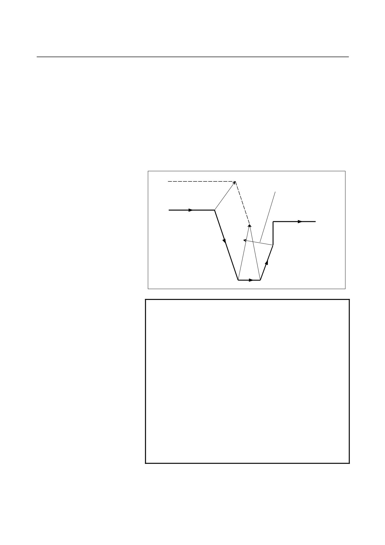
- If further interference with an interference avoidance vector occurs
If the pocket shown in the figure is to be machined, if the number of
blocks to read is 3, the end-point vector of block 1 and the end-point
vector of block 2 are judged to interfere, and an attempt is made to
calculate, as an interference avoidance vector, the intersection vector
of the post-compensation path of block 1 and the post-compensation
path of block 3. In this case, however, the end-point vector of block
3 that is to be calculated next further interferes with the previous
interference avoidance vector. If a further interference occurs to the
interference avoidance vector once created and output, the movement
in the block will not be performed; an alarm will occur immediately
before the block and the tool will stop.
The intersection vectors of
blocks 3 and 4 further
Tool center path
interfere.
Programmed path
Sropped
Block 5
Block 4
Block 1
Block 3
Block 2
NOTE
1 For "If it is judged dangerous to avoid interference"
and "If further interference with an interference
avoidance vector occurs", by setting parameter
NAA (No. 19607#6) appropriately, it is possible to
suppress an alarm to continue machining. For "If
no interference avoidance vector exists", however,
it is not possible to avoid an alarm regardless of the
setting of this parameter.
2 If a single block stop occurs during interference
avoidance operation, and an operation is performed
which differs from the original movement, such as
manual intervention, MDI intervention, cutter
compensation value change, intersection
calculation is performed with a new path. If such
an operation is performed, therefore, an
interference may occur again although interference
avoidance has been performed once.
- 207 -
6.COMPENSATION FUNCTION
PROGRAMMING
B-64304EN-2/01
6.6.7
Cutter Compensation for Input from MDI
Explanation
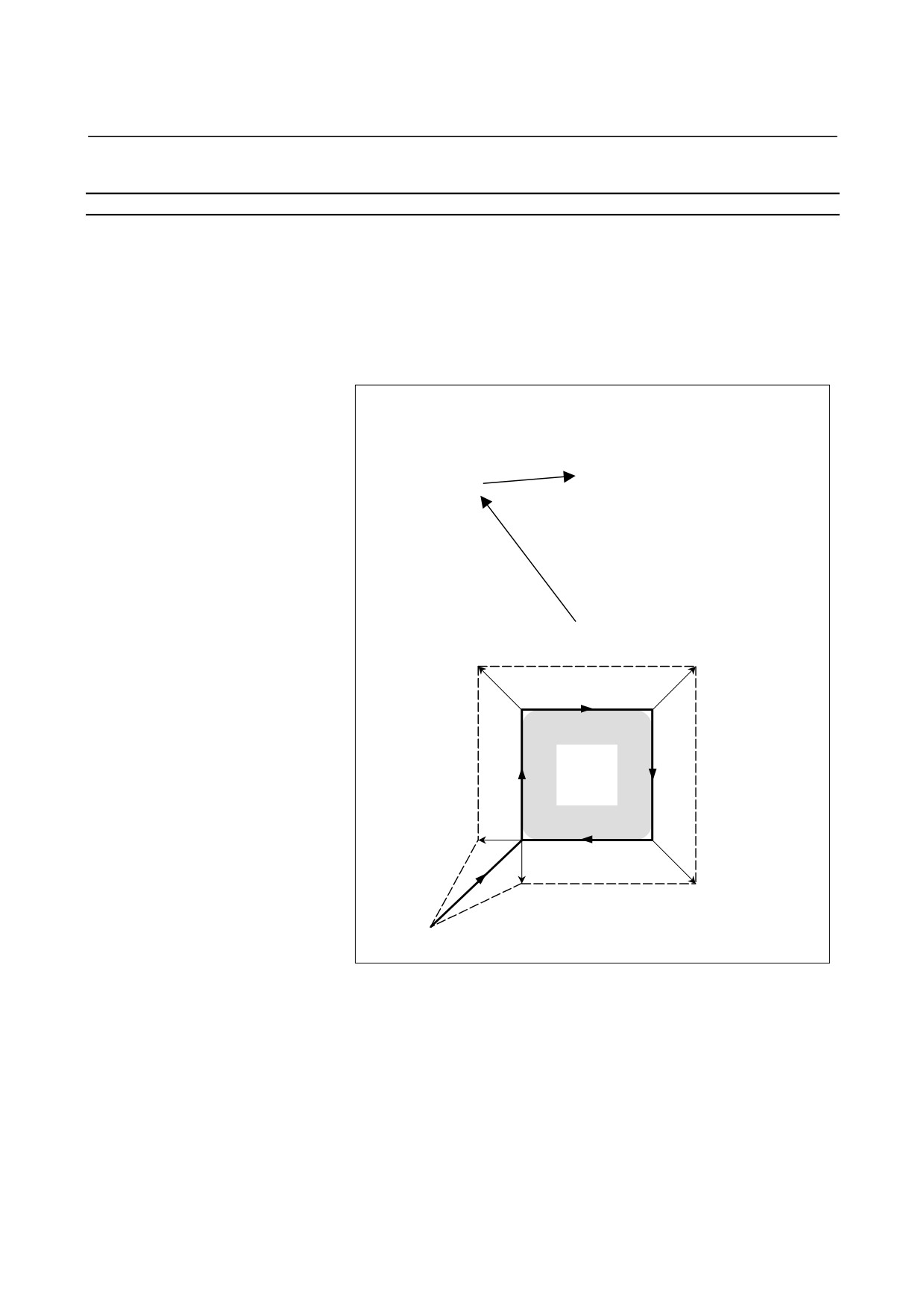
- MDI operation
During MDI operation, that is, if a program command is specified in
MDI mode in the reset state to make a cycle start, intersection
calculation is performed for compensation in the same way as in
memory operation/DNC operation. Compensation is performed in
the same way if a subprogram is called from program memory due to
MDI operation.
Subprogram in program memory
MDI command
G90 G00 X0 Y0 ;
O9000 ;
M98 P9000 ;
N1 G41 G17 G91 G01 X10. Y10.
M02 ;
D1 ;
N2 Y15. ;
N3 X15. ;
N4 Y-15. ;
N5 X-15. ;
N6 G40 X-10. Y-10. ;
M99 ;
N3
N2
N4
N1
N5
N6
- 208 -
B-64304EN-2/01
PROGRAMMING
6.COMPENSATION FUNCTION
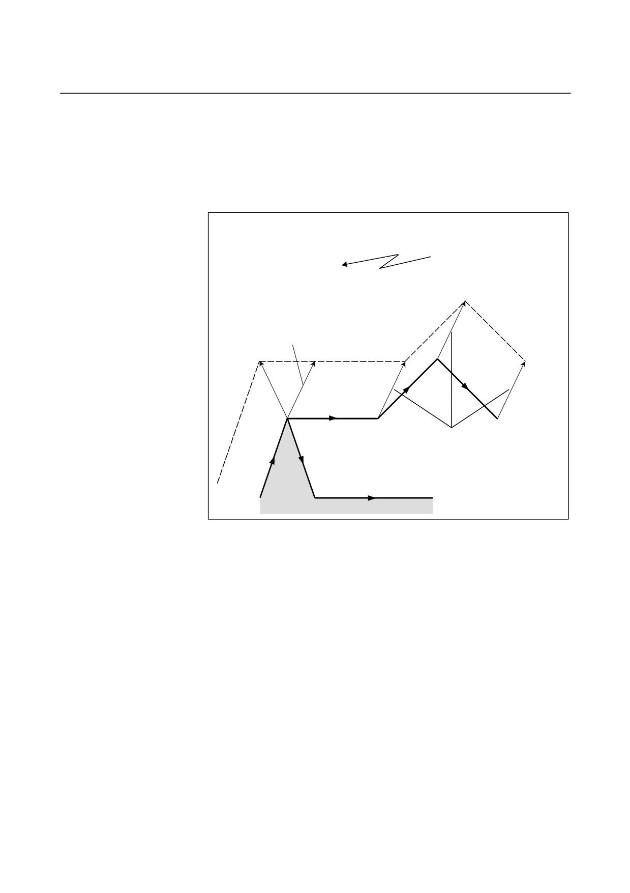
- MDI intervention
If MDI intervention is performed, that is, if a single block stop is
performed to enter the automatic operation stop state in the middle of
memory operation, DNC operation, and the like, and a program
command is specified in MDI mode to make a cycle start, cutter
compensation does not perform intersection calculation, retaining the
last compensation vector before the intervention.
MEM mode
MDI intervention
(G41)
G91 X30. ;
N2 G91 X10. Y30. ;
X20. Y20. ;
N3 X10. Y-30. ;
X20. Y-20. ;
N4 X40. ;
Last compensation vector
MDI intervention
Retained compensation vector
N2 N3
N4
Program command
- 209 -
6.COMPENSATION FUNCTION
PROGRAMMING
B-64304EN-2/01
6.7
CORNER CIRCULAR INTERPOLATION (G39)
By specifying G39 in offset mode during cutter compensation, corner
circular interpolation can be performed. The radius of the corner
circular interpolation equals the compensation value.
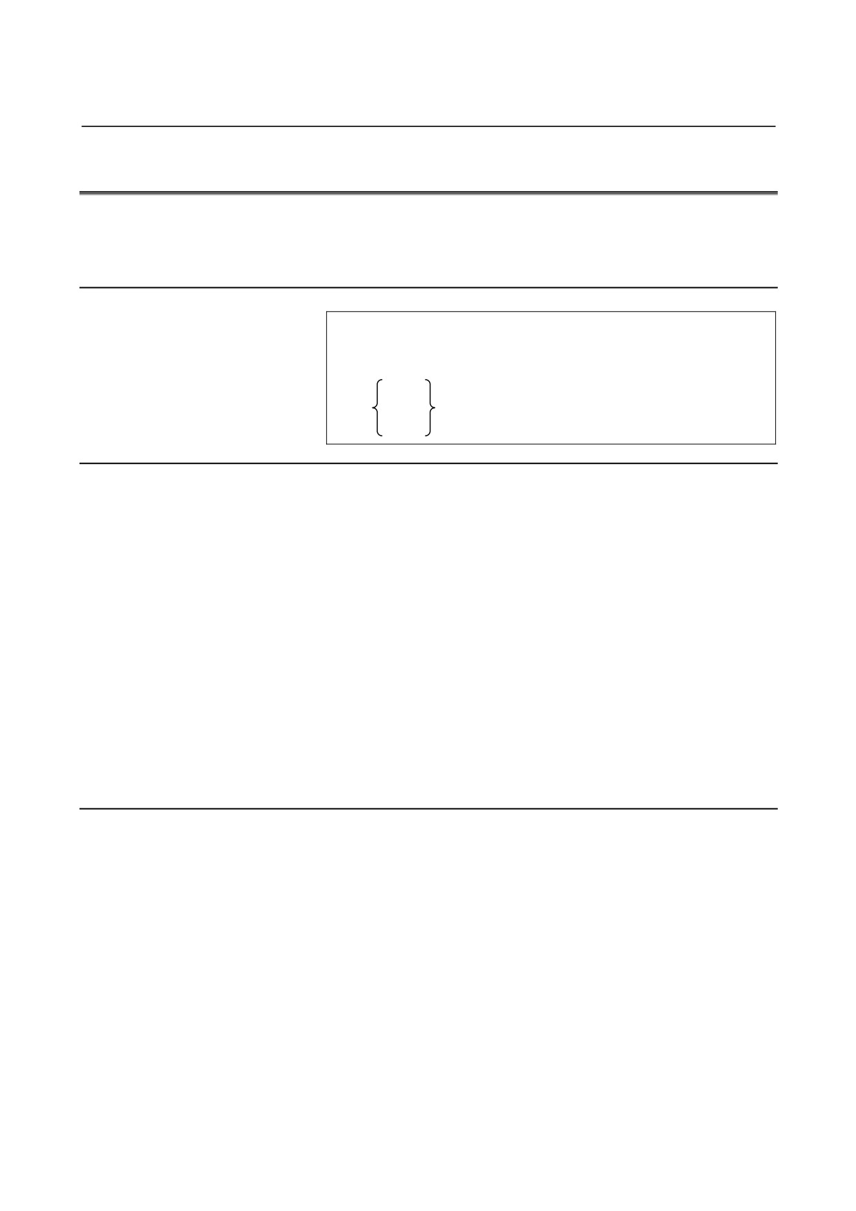
Format
In offset mode
G39 ;
or
I_ J_
G39
I_ K_
;
J_ K_
Explanation
- Corner circular interpolation
When the command indicated above is specified, corner circular
interpolation in which the radius equals compensation value can be
performed. G41 or G42 preceding the command determines whether
the arc is clockwise or counterclockwise. G39 is a one-shot G code.
- G39 without I, J, or K
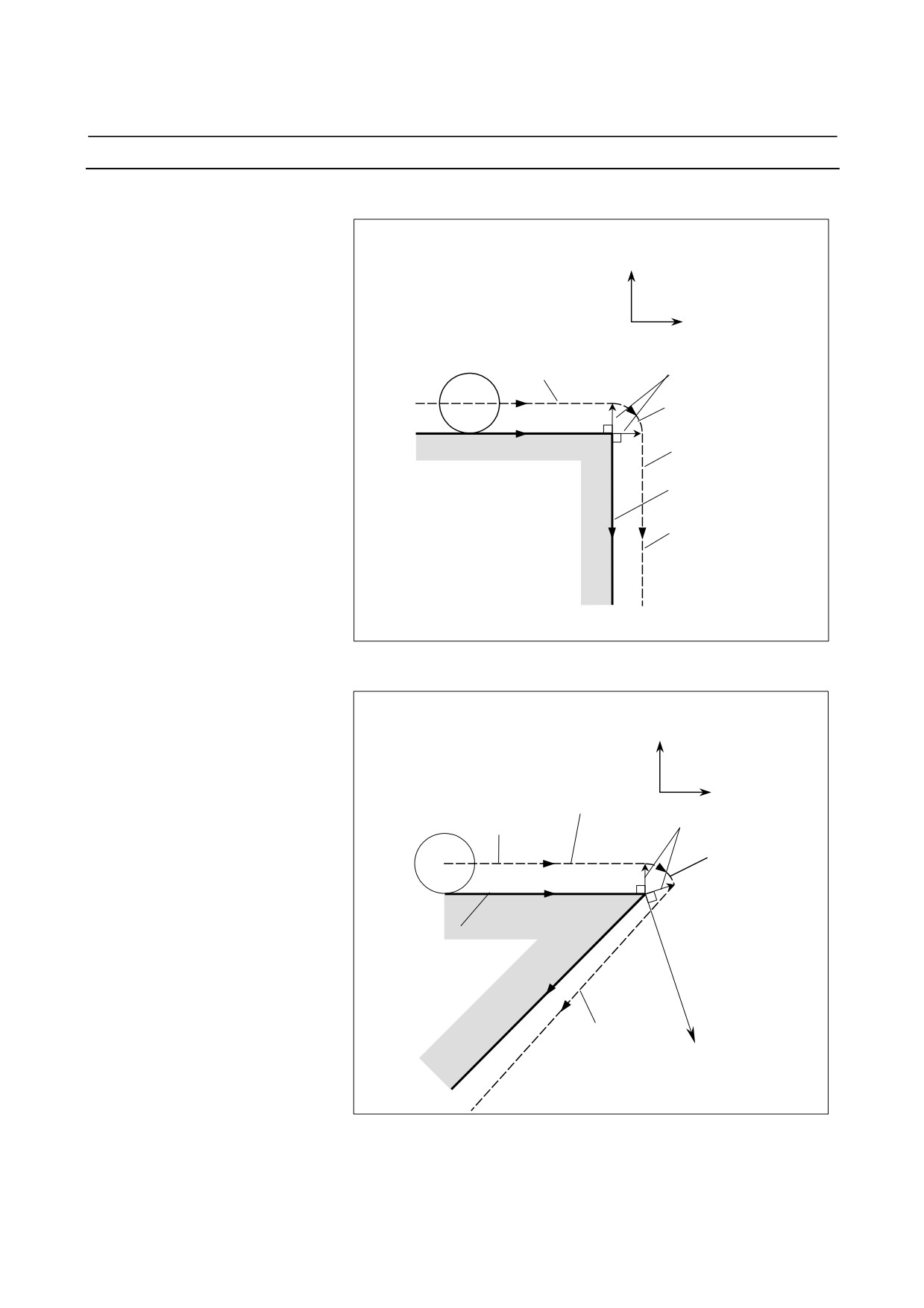
When G39 is programmed, the arc at the corner is formed so that the
vector at the end point of the arc is perpendicular to the start point of
the next block.
- G39 with I, J, and K
When G39 is specified with I, J, and K, the arc at the corner is formed
so that the vector at the end point of the arc is perpendicular to the
vector defined by the I, J, and K values.
Limitation
- Move command
In a block containing G39, no move command can be specified.
Otherwise, an alarm will occur.
- Inner corner
In an inner corner block, G39 cannot be specified. Otherwise,
overcutting will occur.
- Corner arc velocity
If a corner arc is specified with G39 in G00 mode, the corner arc block
velocity will be that of the F command previously specified. If G39
is specified in a state in which no F command has never been specified,
the velocity of the corner arc block will be that specified with
parameter (No. 1411).
- 210 -
B-64304EN-2/01
PROGRAMMING
6.COMPENSATION FUNCTION
Example
- G39 without I, J, or K
:
:
(In offset mode)
(G90)
Y axis
N1 X10.0
;
N2 G39 ;
N3 Y-10.0 ;
:
:
X axis
Block N1
Offset vector
Block N2 (Corner arc)
(10.0, 0.0)
Block N3
Programmed path
Tool center path
(10.0, -10.0)
- G39 with I, J, and K
:
:
(In offset mode)
(G90)
Y axis
N1 X10.0 ;
N2 G39 I1.0 J-3.0 ;
N3 X0.0 Y-10.0 ;
:
X axis
:
Block N1
Tool center path
Offset vector
Block N2 (Corner
arc)
(10.0, 0.0)
Programmed
path
Block N3
(I=-1.0, J=3.0)
(0.0, -10.0)
- 211 -
6.COMPENSATION FUNCTION
PROGRAMMING
B-64304EN-2/01
6.8
TOOL COMPENSATION VALUES, NUMBER OF
COMPENSATION VALUES, AND ENTERING VALUES
FROM THE PROGRAM (G10)
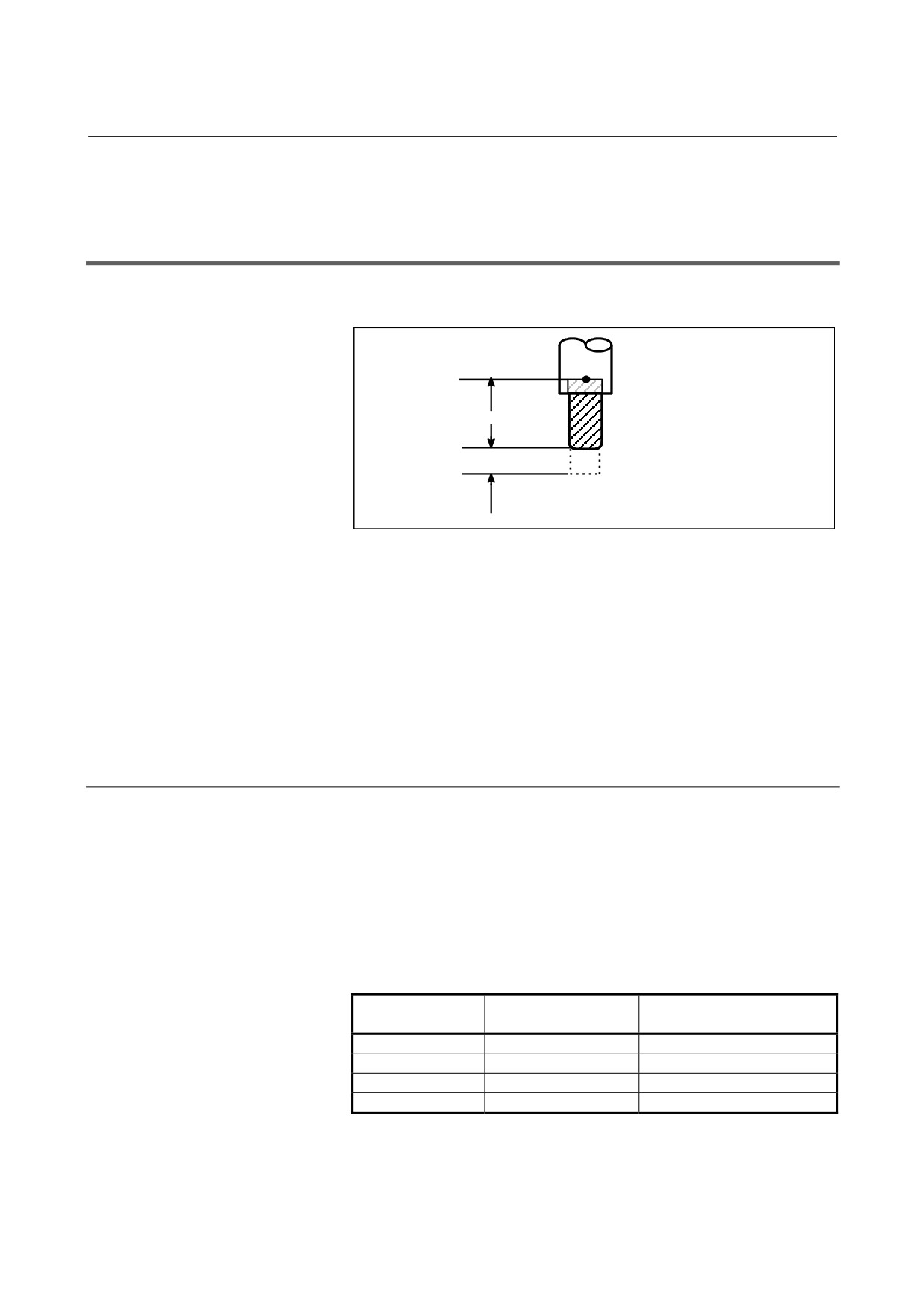
Tool compensation values include tool geometry compensation values
and tool wear compensation (Fig. 6.8 (a)).
Reference
position
OFSG
OFSW
OFSG
: Geometry compensation value
OFSW
: Wear compensation value
Fig. 6.8 (a) Geometric compensation and wear compensation
Tool compensation values can be entered into CNC memory from the
MDI panel (see section III-1.1.1) or from a program.
A tool compensation value is selected from the CNC memory when
the corresponding code is specified after address H or D in a program.
The value is used for tool length compensation, cutter compensation,
or the tool offset.
Two types of tool compensation memories are available according to
the compensation value configuration: tool compensation memory A
and C. One of the types can be selected (bit 6 (NGW) of parameter
No.8136).
Explanation
- Tool compensation memory A (bit 6 (NGW) of parameter No.8136 = 1)
In tool compensation memory A, memory for geometry compensation
and memory for wear compensation are not distinguished from each
other. So, the sum of geometry compensation and wear compensation
values is to be set in the compensation memory. Moreover, no
distinction is made between memory for cutter compensation (for D
code) and memory for tool length compensation (for H code).
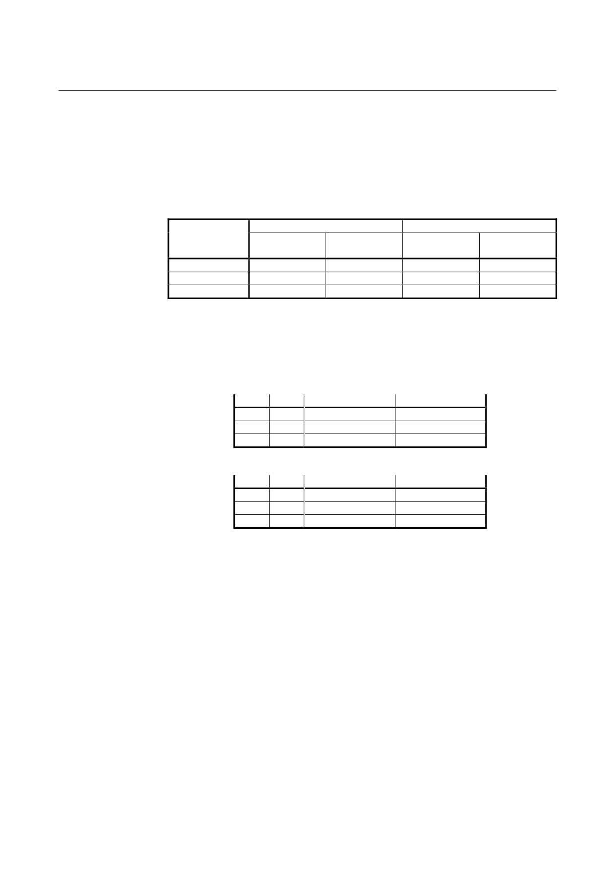
Setting example
Compensation
Compensation value
Common to D code/H code
number
(geometry+wear)
001
10.000
For D code
002
20.000
For D code
003
100.000
For H code
:
:
:
- 212 -
B-64304EN-2/01
PROGRAMMING
6.COMPENSATION FUNCTION
- Tool compensation memory C (bit 6 (NGW) of parameter No.8136 = 0)
In tool compensation memory C, memory for geometry compensation
and memory for wear compensation are prepared separately. So,
geometry compensation values and wear compensation values can be
set separately. Moreover, memory for cutter compensation (for D
code) and memory for tool length compensation (for H code) are
prepared separately.
Setting example
D code
H code
Compensation
For geometry
For wear
For geometry
For wear
number
compensation
compensation
compensation
compensation
001
10.000
0.100
100.000
0.100
002
20.000
0.200
200.000
0.300
:
:
:
:
:
- Unit and valid range of tool compensation values
The unit and valid range of values that can be set as a compensation
value is either of the following, depending on the bits 1 (OFC) and 0
(OFA) parameter No. 5042.
Unit and valid range of tool compensation values (metric input)
OFC
OFA
Unit
Valid range
0
1
0.01mm
±9999.99mm
0
0
0.001mm
±9999.999mm
1
0
0.0001mm
±9999.9999mm
Unit and valid range of tool compensation values (inch input)
OFC
OFA
Unit
Valid range
0
1
0.001inch
±999.999inch
0
0
0.0001inch
±999.9999inch
1
0
0.00001inch
±999.99999inch
- Number of tool compensation data items
Using the bit 5 (NDO) of parameter No. 8136 enables the total number
of items of tool compensation data to be specified as either 400 (bit 5
(NDO) of parameter No. 8136 = "0") or 32 (bit 5 (NDO) of parameter
No. 8136 = "1").
- 213 -

6.COMPENSATION FUNCTION
PROGRAMMING
B-64304EN-2/01
Format
The format for programming depends on the type of tool
compensation memory.
For tool compensation memory A
G10 L11 P_ R_ Q_ ;
P_
: Tool compensation number
R_
: Tool compensation value
Q_
: Imaginary tool nose number
For tool compensation memory C
G10 L_ P_ R_ Q_ ;
L_
: Type of compensation memory
L10 : Geometry compensation value
corresponding to an H code
L11 : Wear compensation value
corresponding to an H code
L12 : Geometry compensation value
corresponding to a D code
L13 : Wear compensation corresponding
to a D code
P_
: Tool compensation number
R_
: Tool compensation value
Q_
: Imaginary tool nose number
By specifying G10, a tool compensation value can be set or modified.
When G10 is specified by absolute input (G90), the specified value is
used as the new tool compensation value.
When incremental input (G91) is used, a specified value added to the
tool compensation value currently set is used as the new tool
compensation value.
NOTE
1 Address R follows the increment system for tool
offset values.
2 If L is omitted for compatibility with the conventional
CNC format, or L1 is specified, the same operation
as when L11 is specified is performed.
- 214 -
B-64304EN-2/01
PROGRAMMING
6.COMPENSATION FUNCTION
6.9
SCALING (G50, G51)
Overview
A programmed figure can be magnified or reduced (scaling).
Two types of scaling are available, one in which the same
magnification rate is applied to each axis and the other in which
different magnification rates are applied to different axes.
The magnification rate can be specified in the program.
Unless specified in the program, the magnification rate specified in the
parameter is applied.
Y
P4
P
3
P4’
P3’
P0
P2’
P1’
P2
P1
0
X
P0
: Scaling center
P1 to P4
: Programmed figure
P1’ to P4’
: Scaled figure
Fig. 6.9 (a) Scaling
NOTE
To enable scaling, set bit 5 (SCL) of parameter No.
8132 to "1".
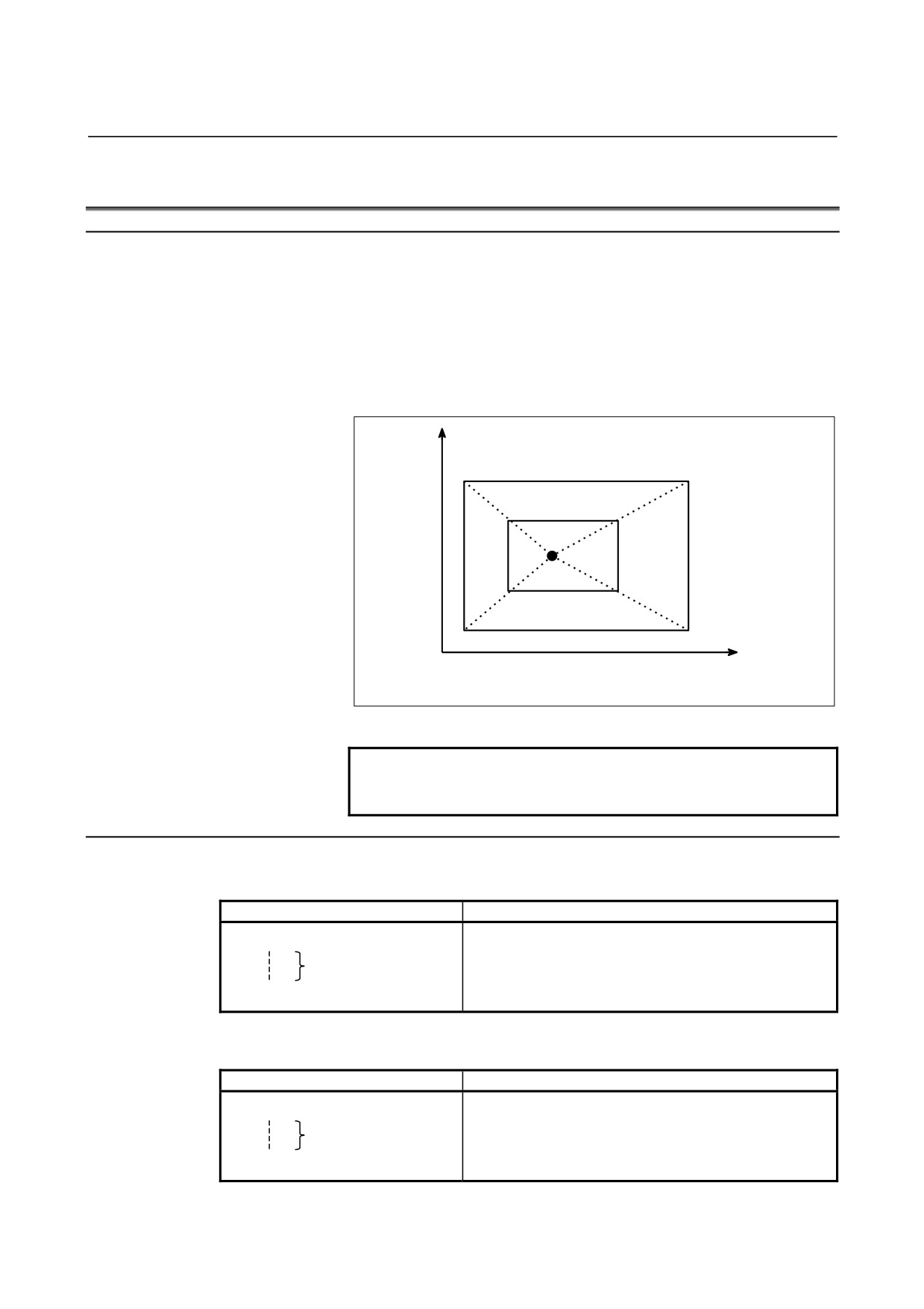
Format
Scaling up or down along all axes at the same rate of magnification
(When parameter XSC (No. 5400#6) = 0)
Format
Meaning of command
G51 IP_P_ ;
Scaling start
IP_
: Absolute command for center coordinate
Scaling is effective.
value of scaling
(Scaling mode)
P_
: Scaling magnification
G50 ;
Scaling cancel
Scaling up or down along each axes at a different rate of magnification (mirror image)
(When parameter XSC (No. 5400#6) = 1)
Format
Meaning of command
G51 IP_I_J_K_; Scaling start
IP_
: Absolute command for center coordinate
Scaling is effective.
value of scaling
(Scaling mode)
I_J_K_
: Scaling magnification for basic 3 axes (X, Y,
and Z axes) respectively
G50 ;
Scaling cancel
- 215 -
6.COMPENSATION FUNCTION
PROGRAMMING
B-64304EN-2/01
CAUTION
1 Specify G51 in a separate block.
2 After the figure is enlarged or reduced, specify G50
to cancel the scaling mode.
NOTE
1 Entering electronic calculator decimal point input
mode (bit 0 (DPI) of parameter No. 3401 = 1) does
not cause the units of the magnification rates P, I, J,
and K to change.
2 Setting the least input increment equal to 10 times
the least command increment (bit 7 (IPR) of
parameter No. 1004 = 1) does not cause the units
of the magnification rates P, I, J, and K to change.
3 An attempt to specify 0 as a magnification rate
causes alarm PS0142 to occur in a G51 block.
Explanation
- Axis for which scaling is to be enabled
For the axis for which scaling is to be enabled, set bit 0 (SCL) of
parameter No. 5401 to 1.
- Minimum unit of scaling magnification
Least input increment of scaling magnification is: 0.001 or 0.00001.
It is 0.00001 (one hundred thousandth) if bit 7 (SCR) of parameter No.
5400 is 0 and 0.001 if it is 1.
- Scaling center
Even in incremental command
(G91) mode, the scaling center
coordinates IP_ specified in the G51 block are assumed those of an
absolute position.
If the scaling center coordinates are omitted, the position assumed
when G51 is specified is assumed the scaling center.
CAUTION
With the move command subsequent to the G51
block, execute an absolute (G90 mode) position
command.
If no absolute position command is executed after
the G51 block, the position assumed when G51 is
specified is assumed the scaling center; once an
absolute position command is executed, the scaling
center assumes the coordinates specified in the
G51 block, after that block.
- 216 -
B-64304EN-2/01
PROGRAMMING
6.COMPENSATION FUNCTION
- Scaling along each axis at the same rate of magnification
Set bit 6 (XSC) of parameter No. 5400 to 0.
If the scaling magnification P is not specified, the magnification set in
parameter No. 5411 is used.
Decimal point input is not accepted as the magnification P. If decimal
point input is made, alarm PS0007 will occur.
A negative value cannot be specified as the magnification P. If a
negative value is specified, alarm PS0006 will occur.
The allowable magnification range is from 0.00001 to 9999.99999.
- Scaling of each axis, programmable mirror image (negative magnification)
Each axis can be scaled by different magnifications. Also when a
negative magnification is specified, a mirror image is applied. The
axis subject to the mirror image is the one that contains the scaling
center.
Set bit
6 (XSC) of parameter No. 5400to 1 to validate each axis
scaling (mirror image).
Using I, J, and K, specify the scaling magnifications for the basic 3
axes (X to Z axes). Use parameter No. 1022 to specify which axes to
use as the basic 3 axes. For those of the X to Z axes for which I, J,
and K are not specified and for axes other than the basic 3 axes, the
magnification set with parameter No. 5421 is used.
A value other than 0 must be set to parameter No. 5421.
Decimal point programming can not be used to specify the rate of
magnification (I, J, K).
Magnification can be set within the range of
±0.00001 to
±9999.99999.
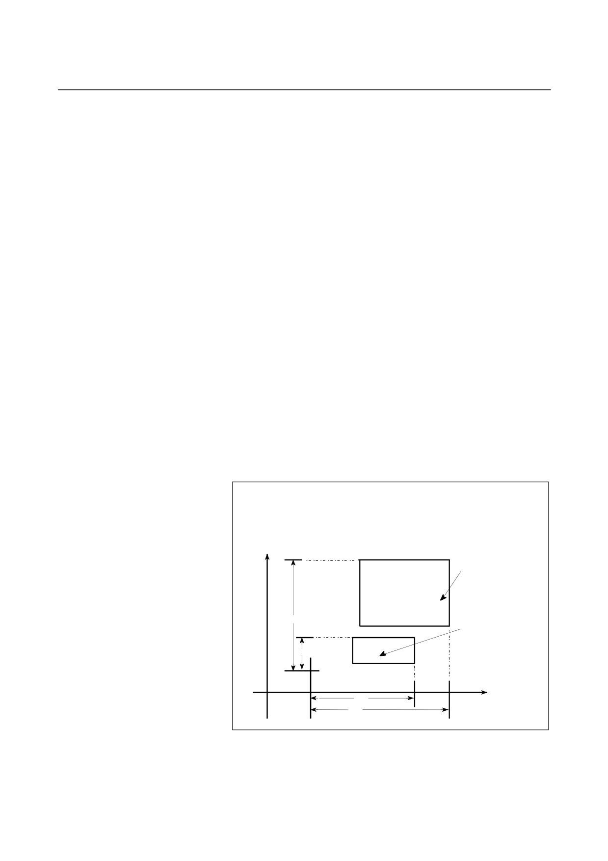
a/b
: Scaling magnification of X axis
c/d
: Scaling magnification of Y axis
o
: Scaling center
Y axis
Programmed figure
d
Scaled figure
c
o
X axis
a
b
Fig. 6.9 (b) Scaling of each axis
- 217 -
6.COMPENSATION FUNCTION
PROGRAMMING
B-64304EN-2/01
CAUTION
Specifying the following commands at the same
time causes them to be executed in the order
indicated below:
<1> Programmable mirror image (G51.1)
<2> Scaling (G51) (including a mirror image with a
negative magnification)
<3> Mirror image due to the external switch of the
CNC or the settings of the CNC
In this case, the programmable mirror image is
effective to the scaling center and magnification as
well.
To specify G51.1 and G51 at the same time,
specify them in this order; to cancel them, specify
them in the reverse order.
- 218 -
B-64304EN-2/01
PROGRAMMING
6.COMPENSATION FUNCTION
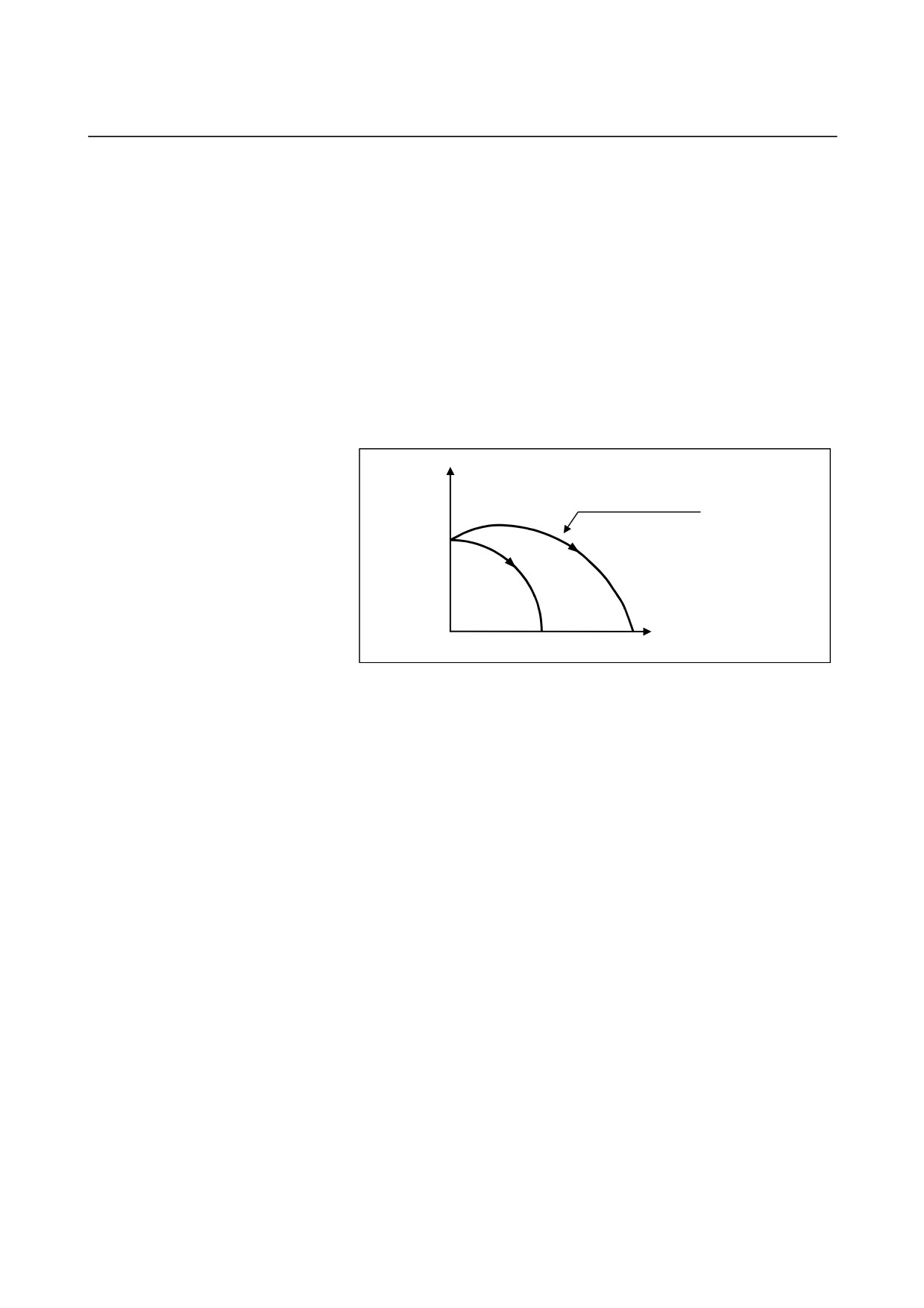
- Scaling of circular interpolation
Even if different magnifications are applied to each axis in circular
interpolation, the tool will not trace an ellipse.
G90 G00 X0.0 Y100.0 Z0.0;
G51 X0.0 Y0.0 Z0.0 I2000 J1000;
(A magnification of 2 is applied to the X-component and a
magnification of 1 is applied to the Y-component.)
G02 X100.0 Y0.0 I0 J-100.0 F500;
Above commands are equivalent to the following command:
G90 G00 X0.0 Y100.0 Z0.0;
G02 X200.0 Y0.0 I0 J-100.0 F500;
(Because the end point is not on an arc, spiral interpolation is
assumed.)
Y
Scaled shape
X
(0,0)
(100.0)
(200.0)
Fig. 6.9 (c) Scaling for circular interpolation1
Even for an R-specified arc, scaling is applied to each of I, J, and K
after the radius value (R) is converted into a vector in the center
direction of each axis.
If, therefore, the above G02 block contains the following R-specified
arc, the operation will be same as that in which I and J are specified.
G02 X100.0 Y0.0 R100.0 F500 ;
- 219 -
6.COMPENSATION FUNCTION
PROGRAMMING
B-64304EN-2/01
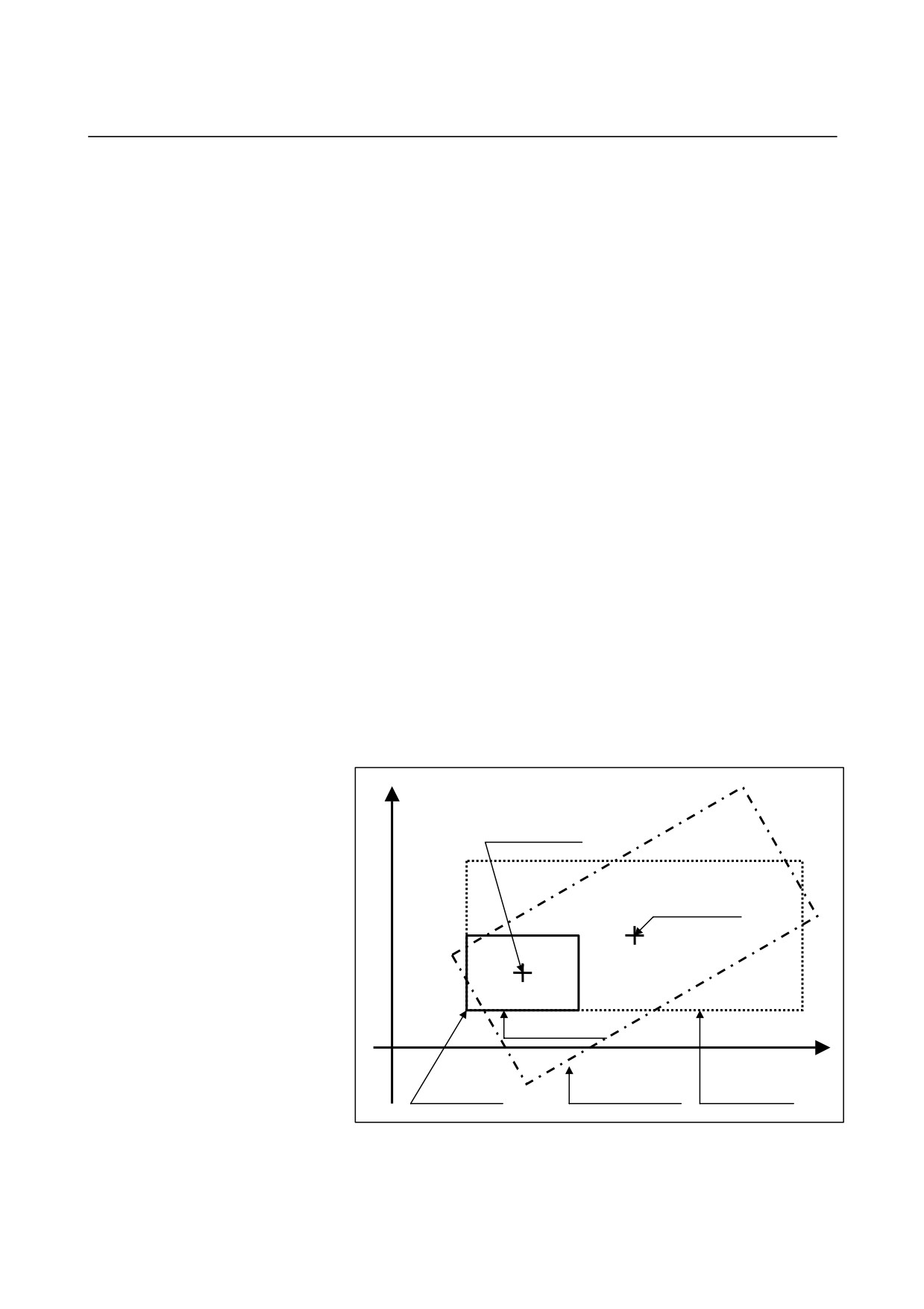
- Scaling and coordinate system rotation
If both scaling and coordinate system rotation are specified at the
same time, scaling is performed first, followed by coordinate system
rotation. In this case, scaling is effective to the rotation center as
well.
To specify both of them, specify scaling first and then coordinate
system rotation. To cancel them, specify them in the reverse order.
Example
Main program
O1
G90 G00 X20.0 Y10.0 ;
M98 P1000 ;
G51 X20.0 Y10.0 I3000 J2000 ; (x 3 in the X direction and x 2
in the Y direction)
M98 P1000 ;
G17 G68 X35.0 Y20.0 R30. ;
M98 P1000 ;
G69 ;
G50 ;
M30 ;
Subprogram
O1000 ;
G01 X20.0 Y10.0 F500 ;
G01 X50.0 ;
G01 Y30.0 ;
G01 X20.0 ;
G01 Y10.0 ;
M99 ;
Y
Rotation center
of coordinate
system before
scaling
Rotation center of
coordinate system
after scaling
Original program
X
Shape after
coordinate system
Scaling center
rotation
Scaled shape
Fig. 6.9 (d) Scaling and coordinate system rotation
- 220 -
B-64304EN-2/01
PROGRAMMING
6.COMPENSATION FUNCTION
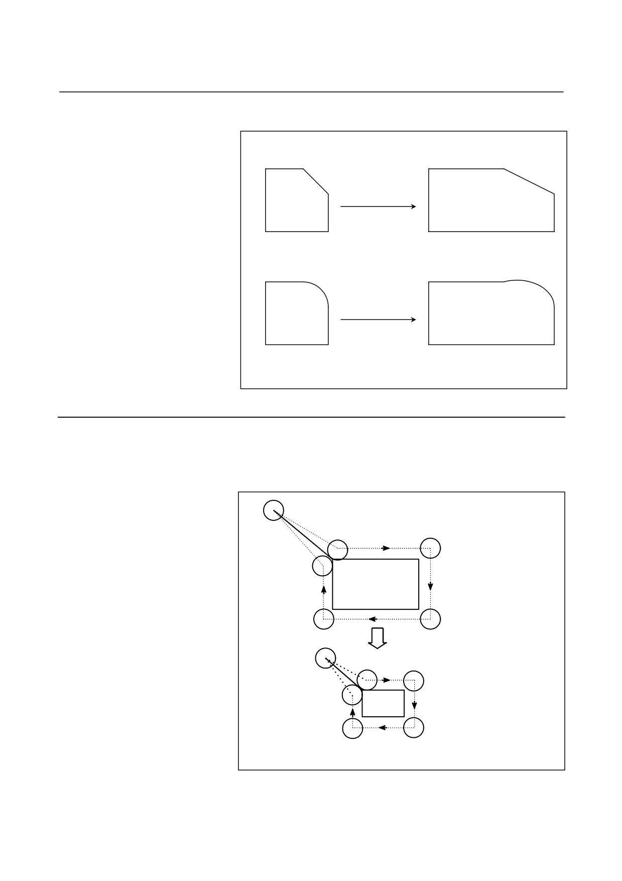
- Scaling and optional chamfering/corner R
Chamfering
Scaling
x 2 in the X direction
x 1 in the Y direction
Corner R
Scaling
x 2 in the X direction
x 1 in the Y direction
If different magnifications are applied to the individual axes, corner R results in
a spiral, not an arc, because scaling is applied to the end point and radius of
the arc.
Fig. 6.9 (e) Scaling and optional chamfering/corner R
Limitation
- Tool compensation
This scaling is not applicable to cutter compensation values, tool
length compensation values, and tool offset values (Fig. 6.9 (f) ).
Programmed figure
Scaled figure
Cutter compensation values are not scaled.
Fig. 6.9 (f) Scaling during cutter compensation
- 221 -
6.COMPENSATION FUNCTION
PROGRAMMING
B-64304EN-2/01
- Invalid scaling
Scaling is not applied to the travel distance during canned cycle
shown below.
• Cut-in value Q and retraction value d of peck drilling cycle (G83,
G73).
• Fine boring cycle (G76)
• Shift value Q of X and Y axes in back boring cycle (G87).
In manual operation, the travel distance cannot be increased or
decreased using the scaling.
CAUTION
1 If a parameter setting value is employed as a
scaling magnification without specifying P, the
setting value at G51 command time is employed as
the scaling magnification, and a change of this
value, if any, is not effective.
2 Before specifying the G code for reference position
return (G27, G28, G29, G30, etc.) or coordinate
system setting (G52 to G59, G92, etc.), cancel the
scaling mode. If it is specified without canceling
scaling, the alarm PS0412 is issued.
3 If scaling results are rounded by counting fractions
of 5 and over as a unit and disregarding the rest,
the move amount may become zero. In this case,
the block is regarded as a no movement block, and
therefore, it may affect the tool movement by cutter
compensation. See the description of cutter
compensation.
4 Refrain from scaling on a rotation axis for which the
rollover function is enabled. Otherwise, the tool
may rotate in a short-cut manner, possibly resulting
in unexpected movement.
NOTE
1 The position display represents the coordinate
value after scaling.
2 When a mirror image was applied to one axis of the
specified plane, the following results:
(1) Circular command
.........................Direction of rotation is reversed.
(2) Tool radius ⋅ tool nose radius compensation
................................Offset direction is reversed.
(3) Coordinate system rotation
.................................Rotation angle is reversed.
- 222 -
B-64304EN-2/01
PROGRAMMING
6.COMPENSATION FUNCTION
Example
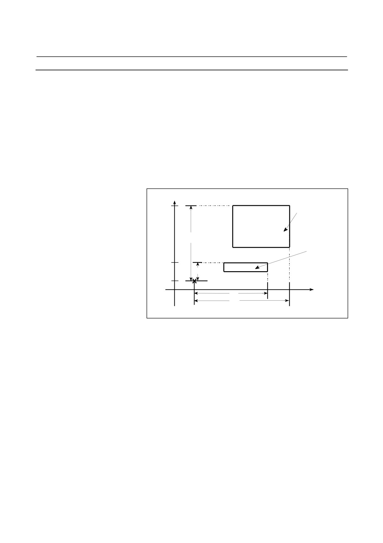
Sample program of a scaling in each axis
O1;
G51 X20.0 Y10.0 I750 J250; (× 0.75 in the X direction, × 0.25 in
the Y direction)
G00 G90 X60.0 Y50.0;
G01 X120.0 F100;
G01 Y90;
G01 X60;
G01 Y50;
G50;
M30;
Y axis
90
Programmed figure
80
(60,50)
Scaled figure
30
20
10
Scaling center
X axis
75
100
20
95
120
Fig. 6.9 (g) Program example of scaling in each axis
- 223 -
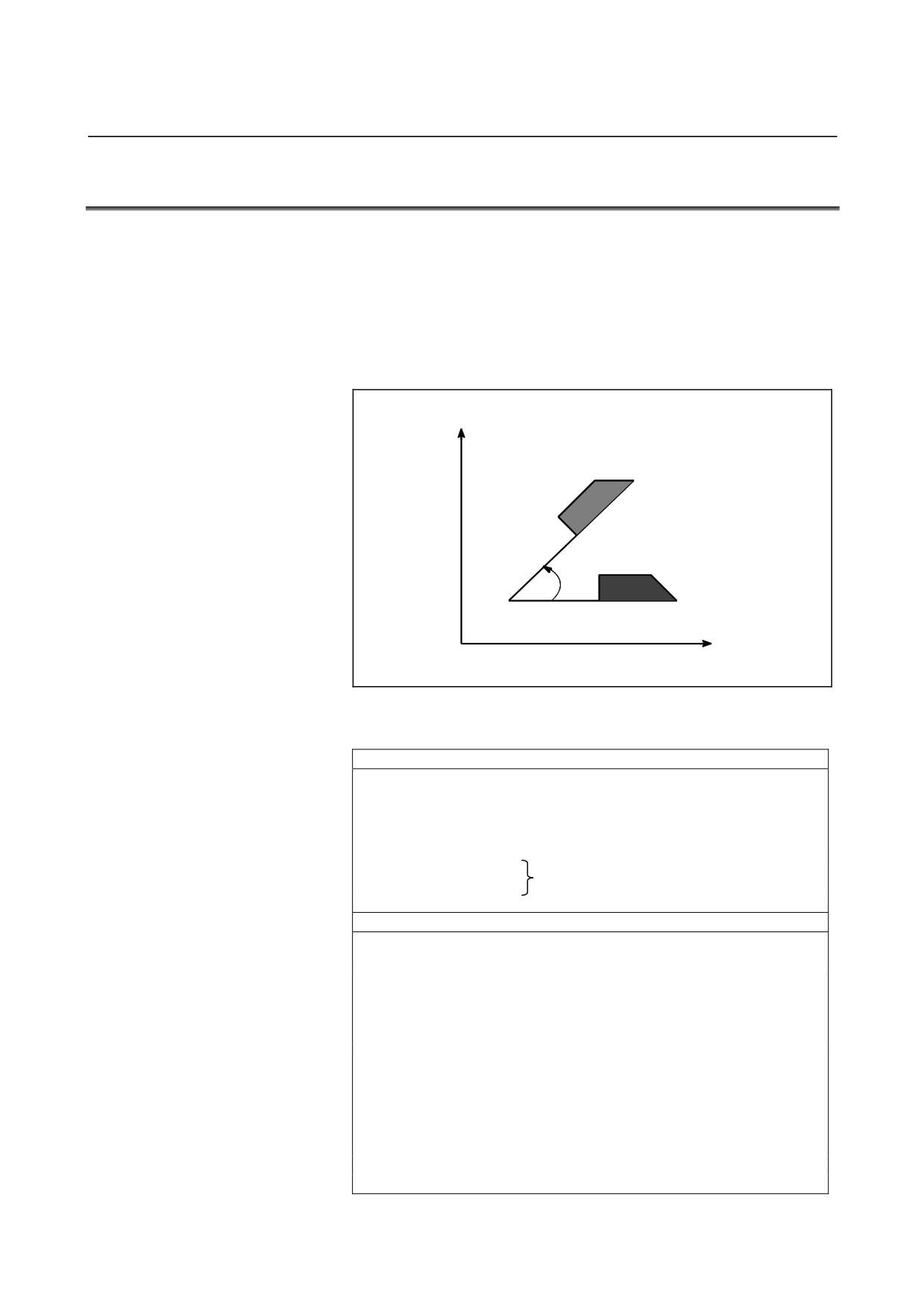
6.COMPENSATION FUNCTION
PROGRAMMING
B-64304EN-2/01
6.10 COORDINATE SYSTEM ROTATION (G68, G69)
A programmed shape can be rotated. By using this function it
becomes possible, for example, to modify a program using a rotation
command when a workpiece has been placed with some angle rotated
from the programmed position on the machine. Further, when there is
a pattern comprising some identical shapes in the positions rotated
from a shape, the time required for programming and the length of the
program can be reduced by preparing a subprogram of the shape and
calling it after rotation.
Y
Angle of rotation
Center of rotation
X
0
Fig. 6.10 (a) Coordinate system rotation
Format
Format
G17
Start rotation of a coordinate system.
G18
G68 α_β_ R_ ;
G19
:
Coordinate system rotation mode
(The coordinate system is rotated.)
G69 ;
Coordinate system rotation cancel command
Meaning of command
G17 (G18 or G19) :
Select the plane in which contains the figure
to be rotated.
α_β_ Absolute programming for two of the X_, Y_, and Z_ axes that
correspond to the current plane selected by a command (G17,
G18, or G19). The command specifies the coordinates of the
center of rotation for the values specified subsequent to G68
R_
Angular displacement with a positive value indicates counter
clockwise rotation. Parameter RIN (No. 5400#0) selects
whether the specified angular displacement is always
considered an absolute value or is considered an absolute or
incremental value depending on the specified G code (G90 or
G91).
Least input increment :
0.001 deg
Valid data range :
-360,000 to 360,000
- 224 -

B-64304EN-2/01
PROGRAMMING
6.COMPENSATION FUNCTION
Y
Angle of rotation R (incremental value)
Center of
Angle of rotation (absolute value)
rotation
(α, β)
X
Fig. 6.10 (b) Coordinate system rotation
NOTE
When a decimal fraction is used to specify angular
displacement (R_), the 1's digit corresponds to
degree units.
Explanation
- G code for selecting a plane: G17,G18 or G19
The G code for selecting a plane (G17,G18,or G19) can be specified
before the block containing the G code for coordinate system rotation
(G68). G17, G18 or G19 must not be designated in the mode of
coordinate system rotation.
- Incremental programming in coordinate system rotation mode
The center of rotation for an incremental programming programmed
after G68 but before an absolute programming is the tool position
when G68 was programmed (Fig. 6.11 (c)).
- Center of rotation
When α_β_ is not programmed, the tool position when G68 was
programmed is assumed as the center of rotation.
- Angular displacement
When R_ is not specified, the value specified in parameter No. 5410 is
assumed as the angular displacement.
To specify angular displacement
(R_) in
0.00001 degrees
(one
hundred-thousandth), set parameter FRD (No. 11630#0) to 1. In this
case, angular displacement R is specified within the range of
-36000000 to 36000000.
- Coordinate system rotation cancel command
The G code used to cancel coordinate system rotation (G69) may be
specified in a block in which another command is specified.
- Tool compensation
Cutter compensation, tool length compensation, tool offset, and other
compensation operations are executed after the coordinate system is
rotated.
- 225 -