FANUC Series 0i-MODEL D, Series 0i Mate-MODEL D. For Machining Center System USER’S MANUAL - page 6
6.COMPENSATION FUNCTION
PROGRAMMING
B-64304EN-2/01
CAUTION
8 If reference position return (G28 or G30) has been
specified, tool length compensation is canceled for
the axis specified at the time of positioning on the
reference point; however, tool length compensation
is not canceled for an un-specified axis. If
reference position return has been specified in the
same block as that containing tool length
compensation cancel (G49), tool length
compensation is canceled for both the specified and
un-specified axes at the time of positioning on the
mid-point.
9 With a machine coordinate system command
(G53), tool length compensation is canceled for the
axis specified at the time of positioning on the
specified point.
10 The tool length compensation vector canceled by
specifying G53, G28, or G30 during tool length
compensation is restored as described below:
• For tool length compensation types A and B, if
parameter EVO (No. 5001#6) is 1, the vector is
restored in the block buffered next; for all of tool
length compensation types A, B, and C, it is
restored in a block containing an H, G43, or G44
command if parameter is 0.
11 When a tool length compensation shift type is used,
if the start or cancellation of a tool length
compensation or other command is specified cutter
compensation mode, look-ahead is not performed.
As a result, overcutting or undercutting may occur
before or after the block in which the start or
cancellation is specified. Thus, specify the start and
cancellation of tool length compensation before the
entry to cutter compensation mode or at a location
where machining is not affected.
- 136 -
B-64304EN-2/01
PROGRAMMING
6.COMPENSATION FUNCTION
6.3
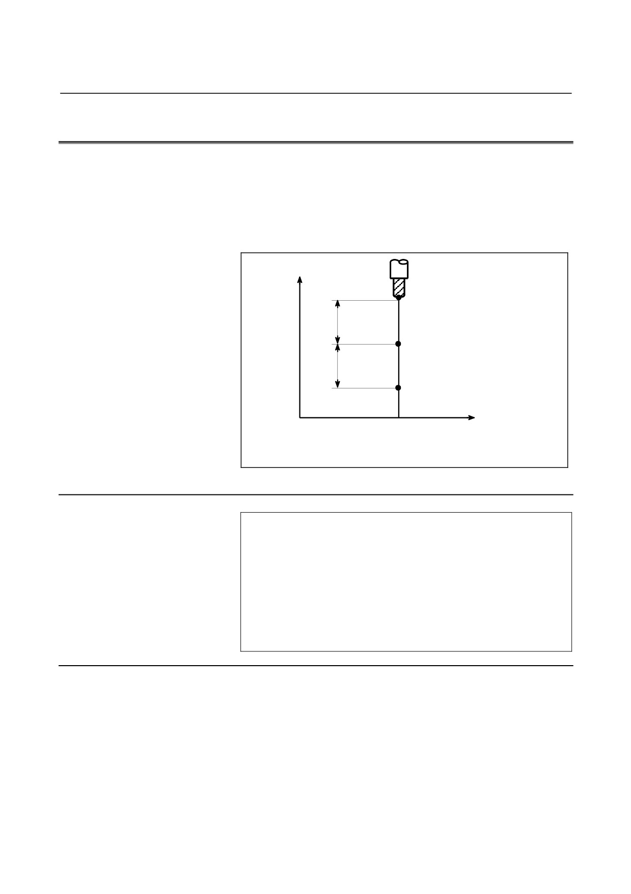
AUTOMATIC TOOL LENGTH MEASUREMENT (G37)
By issuing G37 the tool starts moving to the measurement position
and keeps on moving till the approach end signal from the
measurement device is output. Movement of the tool is stopped when
the tool nose reaches the measurement position.
Difference between coordinate value when tool reaches the
measurement position and coordinate value commanded by G37 is
added to the tool length compensation amount currently used.
Z
A (Start point)
Rapid
Measurement position is commanded
traverse
with G37
B (Deceleration position)
Measurement
feedrate
C (Measurement position)
The tool stops when the approach end
signal goes on.
X
0
Compensation value = (Current compensation value) + [(Coordinates of the
point at which the tool is stopped) - (Coordinates of the programmed measure
ment position)]
Fig. 6.3 (a) Automatic tool length measurement
Format
G92 IP_ ;
Sets the workpiece coordinate system.
(It can be set with G54 to G59. See
Chapter "Coordinate System" in User’s
Manual (Common to T/M series.))
Hxx ;
Specifies an offset number for tool
length compensation.
G90 G37 IP_ ; Absolute programming
G37 is valid only in the block in which it is specified.
IP_ indicates the X-, Y-, Z-, or fourth axis.
Explanation
- Setting the workpiece coordinate system
Set the workpiece coordinate system so that a measurement can be
made after moving the tool to the measurement position. The
coordinate system must be the same as the workpiece coordinate
system for programming.
- 137 -
6.COMPENSATION FUNCTION
PROGRAMMING
B-64304EN-2/01
- Specifying G37
Specify the absolute coordinates of the correct measurement position.
Execution of this command moves the tool at the rapid traverse rate
toward the measurement position, reduces the federate halfway, then
continuous to move it until the approach end signal from the
measuring instrument is issued. When the tool nose reaches the
measurement position, the measuring instrument sends an approach
end signal to the CNC which stops the tool.
- Changing the offset value
The difference between the coordinates of the position at which the
tool reaches for measurement and the coordinates specified by G37 is
added to the current tool length compensation value. (If parameter
MDC (No. 6210#6) is 1, it is subtracted.)
Offset value =
(Current compensation value) + [(Coordinates of the position at which
the tool reaches for measurement) - (Coordinates specified by G37)]
These offset values can be manually changed from MDI.
- Alarm
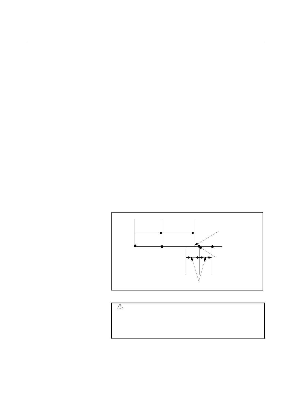
When automatic tool length measurement is executed, the tool moves
as shown in Fig. 6.2 (b). If the approach end signal goes on while the
tool is traveling from point B to point C, an alarm occurs. Unless the
approach end signal goes on before the tool reaches point F, the same
alarm occurs. The alarm number is PS0080.
Deceleration
feedrate
Rapid
(measurement
traverse
feedrate)
Approach end signal ON
A
B
C
D
E F
Start
point
Position commanded
by G37
Permitted range of approach end signal
Fig. 6.3 (b) Tool movement to the measurement position
CAUTION
When a manual movement is inserted into a
movement at a measurement federate, return the
tool to the position before the inserted manual
movement for restart.
- 138 -
B-64304EN-2/01
PROGRAMMING
6.COMPENSATION FUNCTION
NOTE
1
When an H code is specified in the same block as
G37, an alarm is generated. Specify H code before
the block of G37.
2
The measurement speed (FP), γ, and ε are set as
parameters (FP: No. 6241, γ: No. 6251, ε: No.
6254) by the machine tool builder. Make settings
so that e are always positive and γ are always
greater than ε.
3
When tool offset memory A is used, the offset
value is changed. When tool offset memory C is
used, the tool wear compensation value for the H
code is changed.
4
A delay or variation in detection of the
measurement position arrival signal is 0 to 2 msec
on the CNC side excluding the PMC side.
Therefore, the measurement error is the sum of 2
msec and a delay or variation (including a delay or
variation on the receiver side) in propagation of the
skip signal on the PMC side, multiplied by the
feedrate set in parameter No. 6241.
5
A delay or variation in time after detection of the
measurement position arrival signal until a feed
stops is 0 to 8 msec. To calculate the amount of
overrun, further consider a delay in
acceleration/deceleration, servo delay, and delay
on the PMC side.
- 139 -
6.COMPENSATION FUNCTION
PROGRAMMING
B-64304EN-2/01
Example
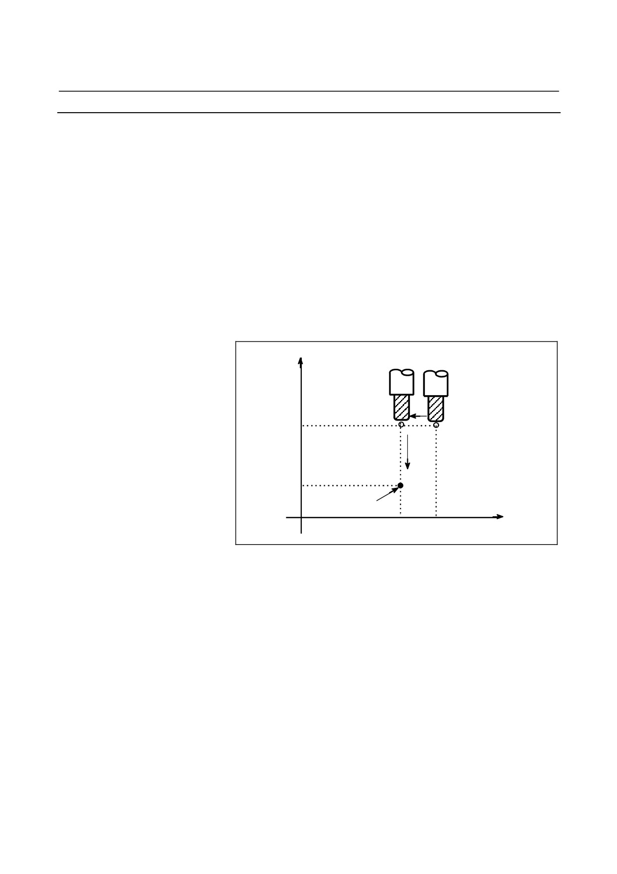
G92 Z760.0 X1100.0 ; Sets a workpiece coordinate system with
respect to the programmed absolute zero
point.
G00 G90 X850.0 ;
Moves the tool to X850.0.
That is the tool is moved to a position that is a
specified distance from the measurement
position along the Z-axis.
H01 ;
Specifies offset number 1.
G37 Z200.0 ;
Moves the tool to the measurement position.
G00 Z204.0 ;
Retracts the tool a small distance along the
Z-axis.
For example, if the tool reaches the measurement position with
Z198.0;, the compensation value must be corrected. Because the
correct measurement position is at a distance of
200 mm, the
compensation value is lessened by 2.0 mm (198.0 - 200.0 = -2.0).
Z
760
200
Measurement
position along Z axis
0
850
1100
X
- 140 -
B-64304EN-2/01
PROGRAMMING
6.COMPENSATION FUNCTION
6.4
TOOL OFFSET (G45 - G48)
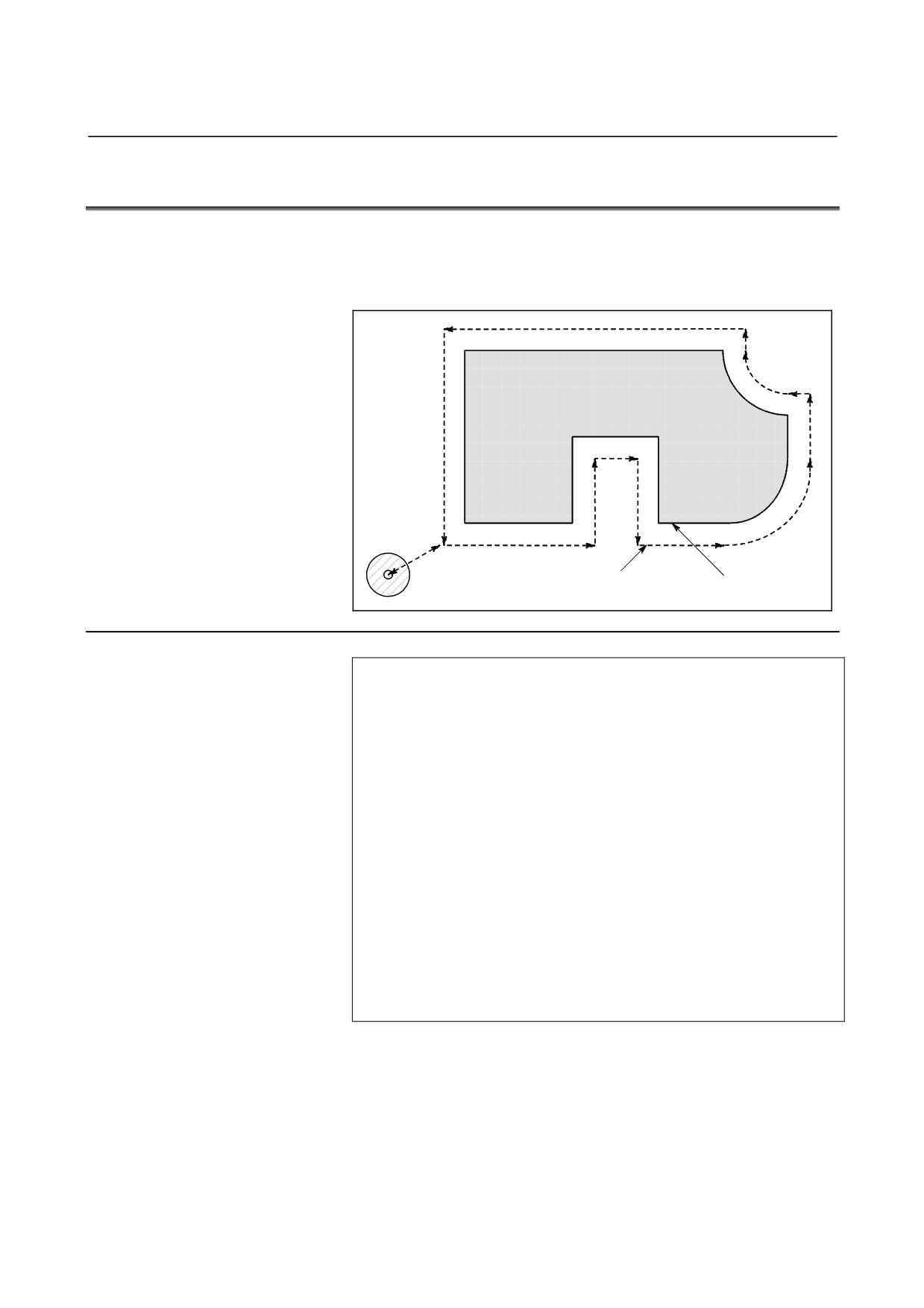
The programmed travel distance of the tool can be increased or
decreased by a specified tool offset value or by twice the offset value.
The tool offset function can also be applied to an additional axis.
Workpiece
Tool center path
Programmed path
Tool
Format
G45 IP_ D_ ; Increase the travel distance by the tool
offset value
G46 IP_ D_ ; Decrease the travel distance by the tool
offset value
G47 IP_ D_ ; Increase the travel distance by twice the
tool offset value
G48 IP_ D_ ; Decrease the travel distance by twice the
tool offset value
G45 to 48
: One-shot G code for increasing or decreasing
the travel distance
IP_
: Command for moving the tool
D_
Code for specifying the tool offset value
* If bit 2 (OFH) of parameter No. 5001 ="0", setting bit 5
(TPH) of parameter No. 5001 to "1" enables address H to
be used as a code for specifying a tool position offset
value.
- 141 -
6.COMPENSATION FUNCTION
PROGRAMMING
B-64304EN-2/01
Explanation
- Increase and decrease
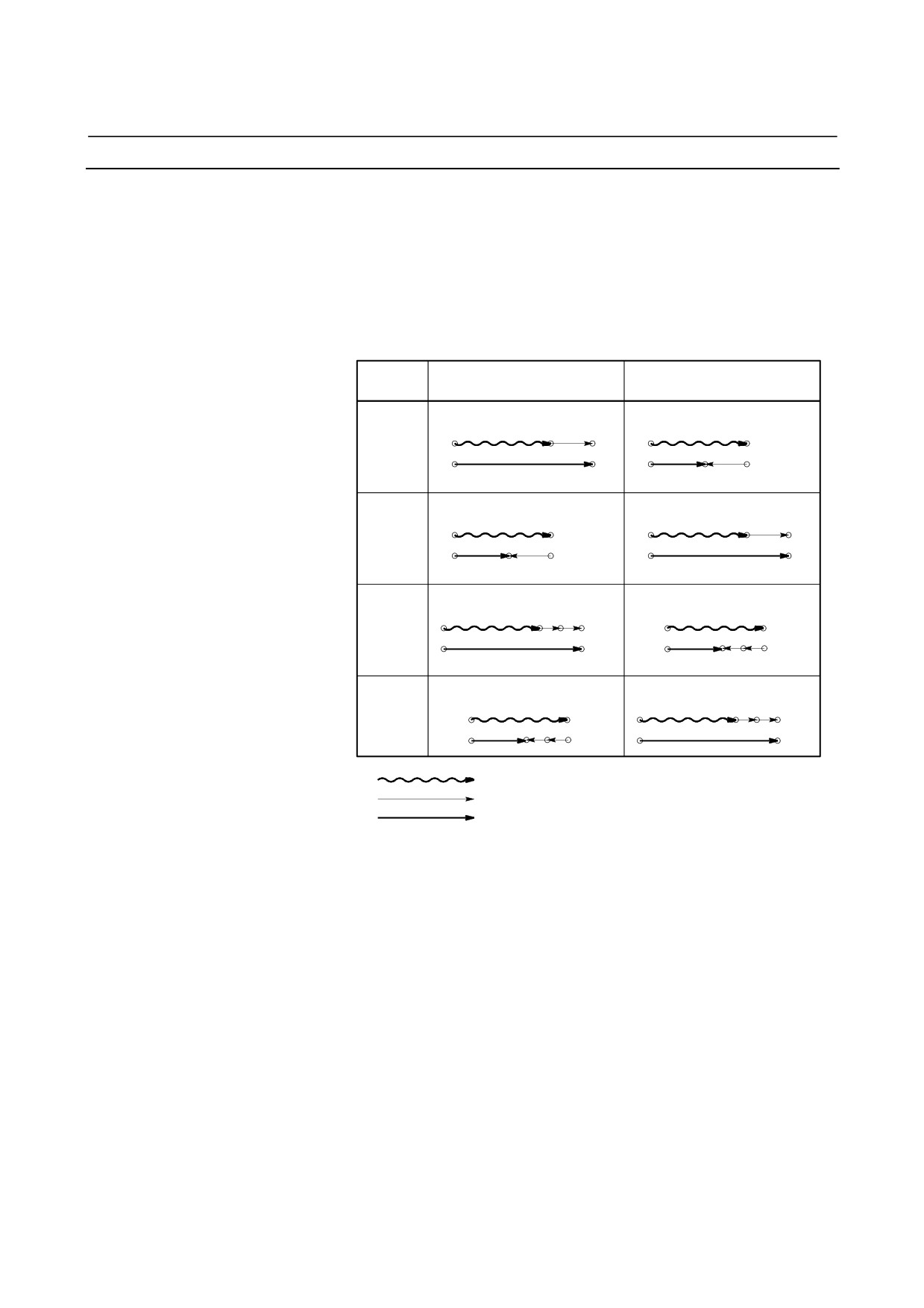
As shown in Table 6.4 (a), the travel distance of the tool is increased
or decreased by the specified tool offset value.
In the absolute mode, the travel distance is increased or decreased as
the tool is moved from the end point of the previous block to the
position specified by the block containing G45 to G48.
Table 6.4 (a) Increase and decrease of the tool travel distance
When a positive tool offset
When a negative tool offset
G code
value is specified
value is specified
Start point
End point
Start point
End point
G45
Start point
End point
Start point
End point
G46
Start point
End point
Start point
End point
G47
Start point
End point
Start point
End point
G48
Programmed movement distance
Tool offset value
Actual movement position
If a move command with a travel distance of zero is specified in the
incremental programming (G91) mode, the tool is moved by the
distance corresponding to the specified tool offset value.
If a move command with a travel distance of zero is specified in the
absolute programming (G90) mode, the tool is not moved.
- Tool offset value
Once selected by D code, the tool offset value remains unchanged
until another tool offset value is selected.
Tool offset values can be set within the following range:
D0 always indicates a tool offset value of zero.
* If bit 2 (OFH) of parameter No. 5001 ="0", setting bit 5 (TPH) of
parameter No. 5001 to "1" enables address H to be used as a code
for specifying a tool position offset value.
- 142 -
B-64304EN-2/01
PROGRAMMING
6.COMPENSATION FUNCTION
CAUTION
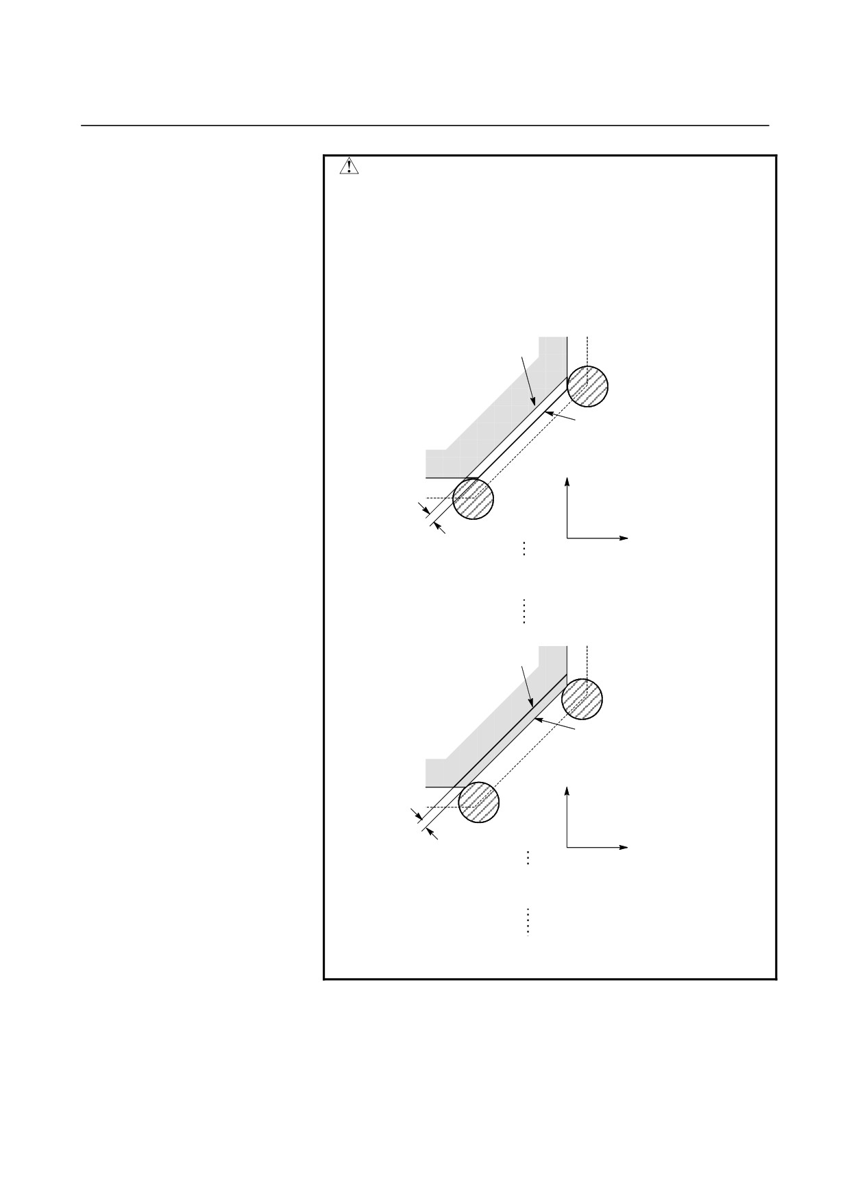
1 When G45 to G48 is specified to n axes (n=1-4)
simultaneously in a motion block, offset is applied to
all n axes.
When the cutter is offset only for cutter radius or
diameter in taper cutting, overcutting or undercutting
occurs.
Therefore, use cutter compensation (G40 - G42)
shown in II-6.4 or 6.6.
Shape actually cut
Desired
shape
Y axis
Overcutting
X axis
G01 X_ F_ ;
G47 X_ Y_ D_ ;
Y_ ;
Desired shape
Shape actually cut
Y axis
Undercutting
X axis
G01 G45 X_ F_ D_;
X_ Y_ ;
G45 Y_ ;
2 G45 to G48 (tool offset) must not be used in the
G41 or G42 (cutter compensation) mode.
- 143 -
6.COMPENSATION FUNCTION
PROGRAMMING
B-64304EN-2/01
NOTE
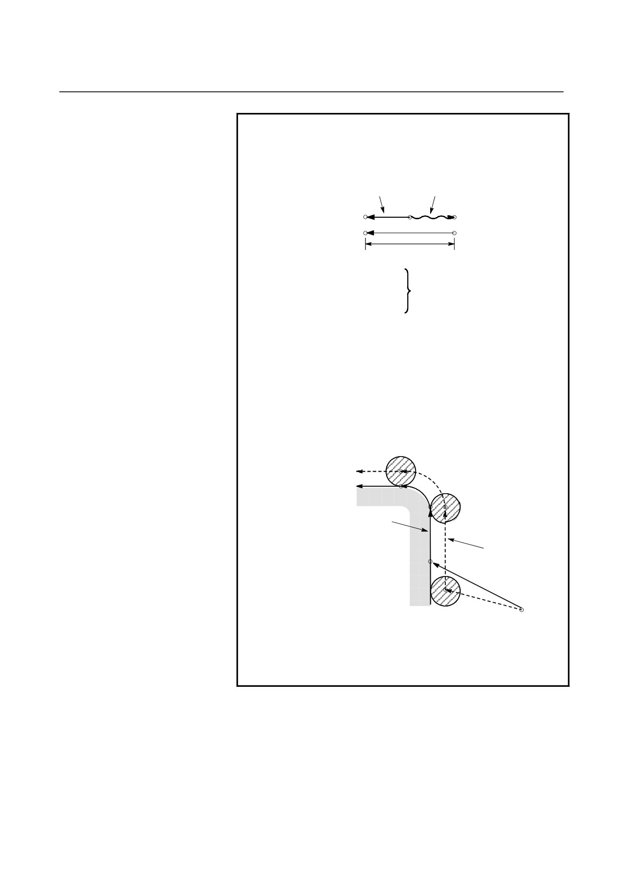
1 When the specified direction is reversed by
decrease as shown in the figure below, the tool
moves in the opposite direction.
Movement of the
Program command
Start
End
position
position
Tool offset value
Example
G46 X2.50 ;
Tool offset value
Equivalent command
+3.70
X-1.20 ;
2
Tool offset can be applied to circular interpolation
(G02, G03) with the G45 to G48 commands only for
1/4 and 3/4 circles using addresses I, J and K by the
parameter setting, providing that the coordinate
system rotation be not specified at the same time.
This function is provided for compatibility with the
conventional CNC program without any cutter
compensation. The function should not be used
when a new CNC program is prepared.
Tool offset for circular interpolation
N4
N3
Programmed tool path
N2
Program
Actual tool path
N1 G46 G00 X_ Y_ D_ ;
N2 G45 G01 Y_ F_ ;
N1
N3 G45 G03 X_ Y_ I_ ;
N4 G01 X_ ;
3
D code should be used in tool offset mode.
4
G45 to G48 are ignored in canned cycle mode.
Perform tool offset by specifying G45 to G48 before
entering canned cycle mode and cancel the offset
after releasing the canned cycle mode.
- 144 -
B-64304EN-2/01
PROGRAMMING
6.COMPENSATION FUNCTION
Example
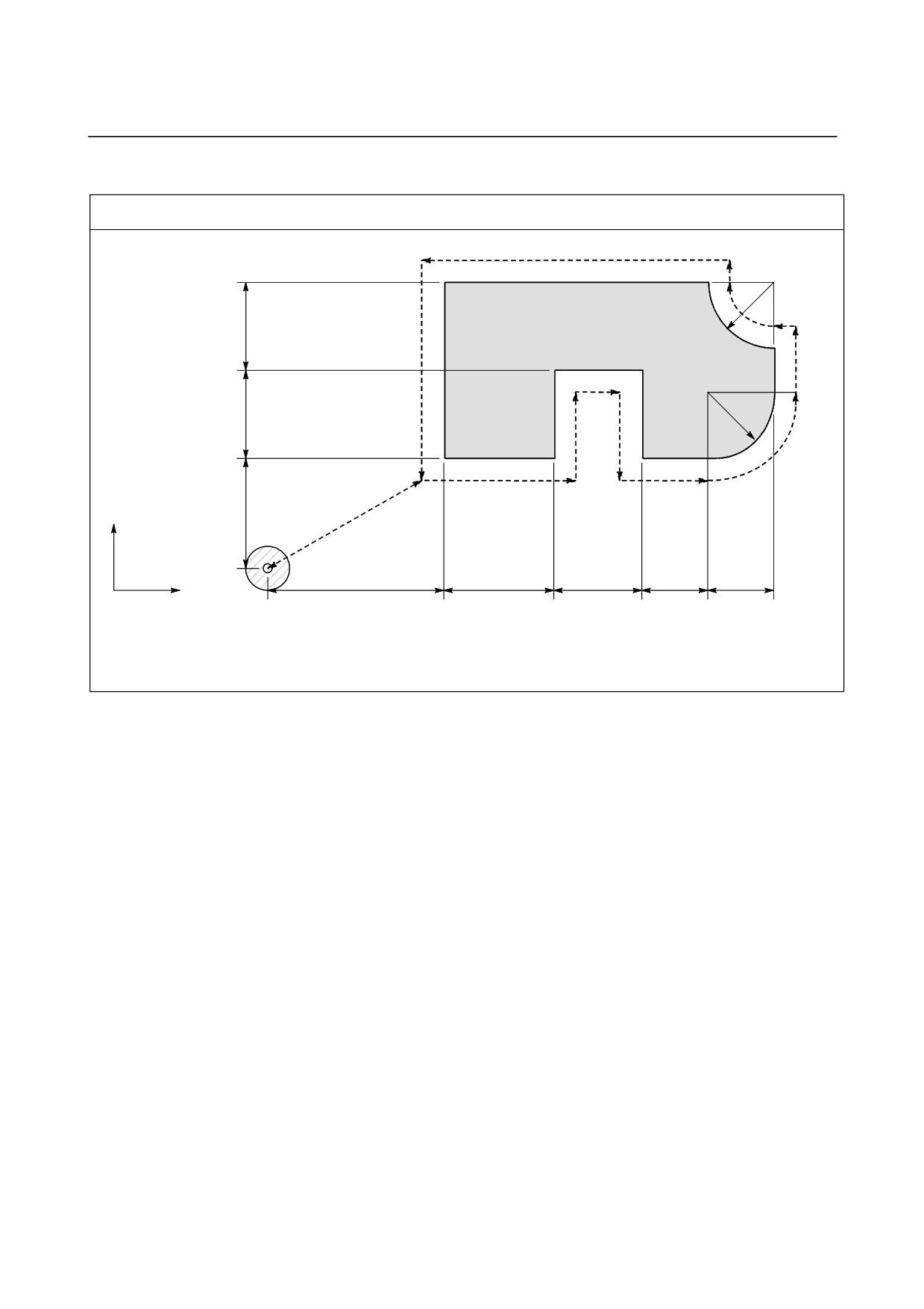
Program using tool offset
N12
N11
30R
N9
40
N10
N13
N8
N4
30R
40
N3
N5
N1
N7
N2
N6
Y axis
50
N14
80
50
40
30
30
X
Origin
Tool diameter
:
20φ
Offset No.
:
01
Tool offset value
:
+10.0
Program
N1 G91 G46 G00 X80.0 Y50.0 D01 ;
N2 G47 G01 X50.0 F120.0 ;
N3 Y40.0 ;
N4 G48 X40.0 ;
N5 Y-40.0 ;
N6 G45 X30.0 ;
N7 G45 G03 X30.0 Y30.0 J30.0 ;
N8 G45 G01 Y20.0 ;
N9 G46 X0 ; (Decreases toward the positive direction for movement
amount "0". The tool moves in the -X direction by the
offset value.)
N10 G46 G02 X-30.0 Y30.0 J30.0 ;
N11 G45 G01 Y0 ; (Increase toward the positive direction for
movement amount "0". The tool moves in the +Y
direction by the offset value.)
N12 G47 X-120.0 ;
N13 G47 Y-80.0 ;
N14 G46 G00 X-80.0 Y-50.0 ;
- 145 -
6.COMPENSATION FUNCTION
PROGRAMMING
B-64304EN-2/01
6.5
OVERVIEW OF CUTTER COMPENSATION (G40-G42)
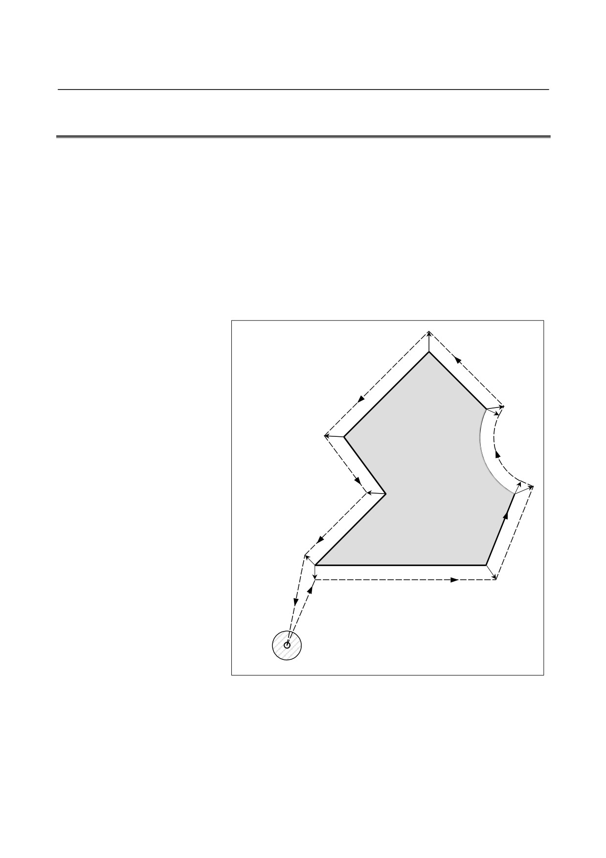
When the tool is moved, the tool path can be shifted by the radius of
the tool (Fig. 6.5 (a)).
To make an offset as large as the radius of the tool, CNC first creates
an offset vector with a length equal to the radius of the tool (start-up).
The offset vector is perpendicular to the tool path. The tail of the
vector is on the workpiece side and the head positions to the center of
the tool.
If a linear interpolation or circular interpolation command is specified
after start-up, the tool path can be shifted by the length of the offset
vector during machining.
To return the tool to the start point at the end of machining, cancel the
cutter compensation mode.
Cutter
compensation
cancel
Start-up
Fig. 6.5 (a) Outline of cutter compensation
- 146 -
B-64304EN-2/01
PROGRAMMING
6.COMPENSATION FUNCTION
Format
- Start up (cutter compensation start)
G00(or G01)G41(or G42) IP_D_;
G41
: Cutter compensation left (Group 07)
G42
: Cutter compensation right (Group 07)
IP_
: Command for axis movement
D_
: Code for specifying as the cutter compensation
value (1-3 digits) (D code)
* Setting bit 2 (OFH) of parameter No. 5001 to "1" enables
address H to be used as a code for specifying a cutter
compensation amount. When bit 2 (OFH) of parameter
No. 5001 = "1", if tool length compensation and cutter
compensation are specified in the same block, the latter
command takes precedence.
- Cutter compensation cancel (offset mode cancel)
G40 IP_;
G40
: Cutter compensation cancel (Group 07)
(Offset mode cancel)
IP_
: Command for axis movement
- Selection of the offset plane
Offset plane
Command for plane selection
IP_
XpYp
G17 ;
Xp_Yp_
ZpXp
G18 ;
Xp_Zp_
YpZp
G19 ;
Yp_Zp_
Explanation
- Offset cancel mode
At the beginning when power is applied the control is in the cancel
mode. In the cancel mode, the vector is always 0, and the tool center
path coincides with the programmed path.
- Start-up
When a cutter compensation command
(G41 or G42, nonzero
dimension word in the offset plane and command 0 in a non-D0 D
code) is specified in the offset cancel mode, the CNC enters the offset
mode.
Moving the tool with this command is called start-up.
Specify positioning (G00) or linear interpolation (G01) for start-up.
If circular interpolation (G02, G03) is specified, alarm PS0034 occurs.
For the start-up and subsequent blocks, the CNC prereads as many
blocks as the number of preread blocks set in the parameter (No.
19625).
- 147 -
6.COMPENSATION FUNCTION
PROGRAMMING
B-64304EN-2/01
- Offset mode
In the offset mode, compensation is accomplished by positioning
(G00), linear interpolation (G01), or circular interpolation (G02, G03).
If three or more blocks that move the tool cannot be read in offset
mode, the tool may make either an excessive or insufficient cut.
If the offset plane is switched in the offset mode, alarm PS0037 occurs
and the tool is stopped.
- Offset mode cancel
In the offset mode, when a block which satisfies any one of the
following conditions is executed, the CNC enters the offset cancel
mode, and the action of this block is called the offset cancel.
1.
G40 has been commanded.
2.
0 has been commanded as the offset number for cutter
compensation (D code).
When performing offset cancel, circular arc command (G02 or G03) is
not available. If these commands are specified, an PS0034 is
generated and the tool stops. In the offset cancel, the control
executes the instructions in that block and the block in the cutter
compensation buffer.
In the meantime, in the case of a single block mode, after reading one
block, the control executes it and stops. By pushing the cycle start
button once more, one block is executed without reading the next
block.
Then the control is in the cancel mode, and normally, the block to be
executed next will be stored in the buffer register and the next block is
not read into the buffer for cutter compensation.
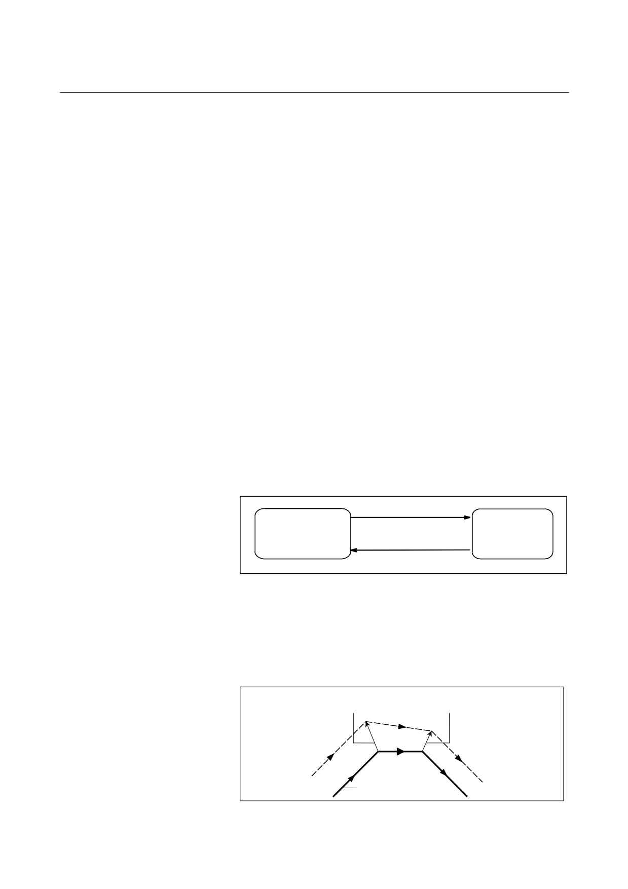
Start up
(G41/G42)
Offset cancel mode
Offset mode
Offset mode cancel
(G40/D0)
Fig. 6.5 (b) Changing the offset mode
- Change of the cutter compensation value
In general, the cutter compensation value shall be changed in the
cancel mode, when changing tools. If the cutter compensation value
is changed in offset mode, the vector at the end point of the block is
calculated for the new cutter compensation value.
Calculated from the cutter
Calculated from the cutter
compensation value in the block N6
compensation value in the block N7
N7
N6
N8
Programmed path
Fig. 6.5 (c) Changing the cutter compensation value
- 148 -
B-64304EN-2/01
PROGRAMMING
6.COMPENSATION FUNCTION
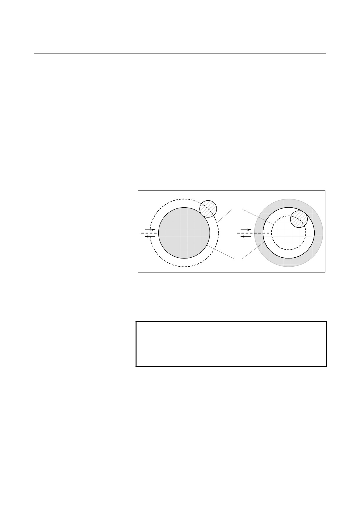
- Positive/negative cutter compensation value and tool center path
If the compensation value is negative (-), distribution is made for a
figure in which G41's and G42's are all replaced with each other on
the program. Consequently, if the tool center is passing around the
outside of the workpiece, it will pass around the inside, and vice versa.
Fig. 6.5 (d) shows one example.
Generally, the compensation value is programmed to be positive (+).
When a tool path is programmed as in <1>, if the compensation value
is made negative (-), the tool center moves as in <2>, and vice versa.
Consequently, the same program permits cutting both male and female
shapes, and any gap between them can be adjusted by the selection of
the compensation value.
Applicable if start-up and cancel is A type.
(See the descriptions
about the start-up of cutter compensation.)
<1>
<2>
Tool center path
Programmed path
Fig. 6.5 (d) Tool center paths when positive and negative cutter
compensation values are specified
- Cutter compensation value setting
Assign a cutter compensation values to the D codes on the MDI panel.
NOTE
The cutter compensation value for which the D
code corresponds to 0 always means 0.
It is not possible to set the cutter compensation
value corresponding to D0.
- 149 -
6.COMPENSATION FUNCTION
PROGRAMMING
B-64304EN-2/01
- Valid compensation value range
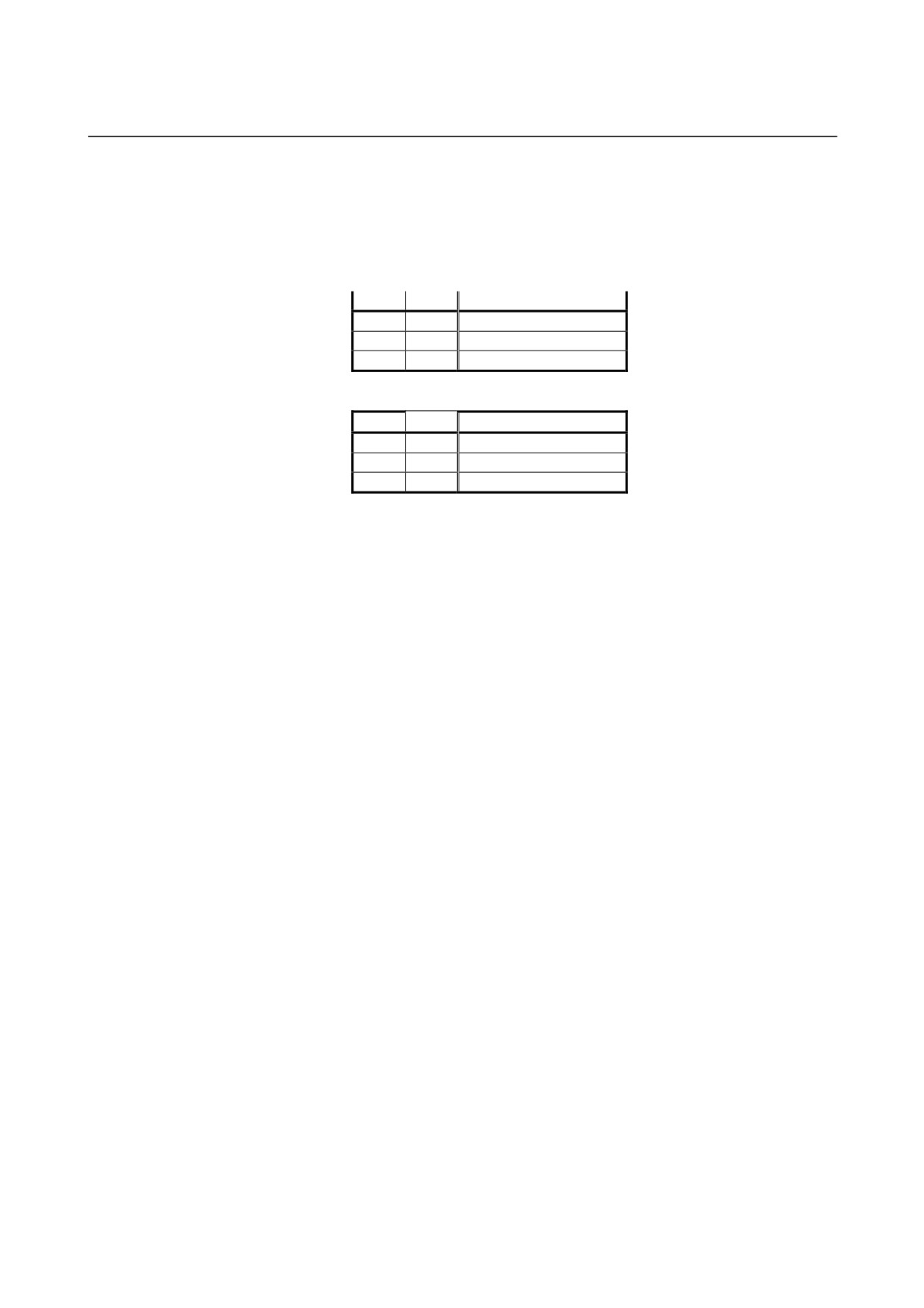
The valid range of values that can be set as a compensation value is
either of the following, depending on the bits 1 (OFC) and 0 (OFA)
parameter No. 5042.
Valid compensation range (metric input)
OFC
OFA
Range
0
1
±9999.99mm
0
0
±9999.999mm
1
0
±9999.9999mm
Valid compensation range (inch input)
OFC
OFA
Range
0
1
±999.999inch
0
0
±999.9999inch
1
0
±999.99999inch
The compensation value corresponding to offset No. 0 always means 0.
It is not possible to set the compensation value corresponding to offset
No. 0.
- Offset vector
The offset vector is the two dimensional vector that is equal to the
cutter compensation value assigned by D code. It is calculated inside
the control unit, and its direction is up-dated in accordance with the
progress of the tool in each block.
The offset vector is deleted by reset.
- Specifying a cutter compensation value
Specify a cutter compensation value with a number assigned to it.
The number consists of 1 to 3 digits after address D (D code).
The D code is valid until another D code is specified. The D code is
used to specify the tool offset value as well as the cutter compensation
value.
- Plane selection and vector
Offset calculation is carried out in the plane determined by G17, G18
and G19, (G codes for plane selection). This plane is called the
offset plane.
Compensation is not executed for the coordinate of a position which is
not in the specified plane. The programmed values are used as they
are.
In simultaneous 3 axes control, the tool path projected on the offset
plane is compensated.
The offset plane is changed during the offset cancel mode. If it is
performed during the offset mode, an PS0037 is displayed and the
machine is stopped.
- 150 -
B-64304EN-2/01
PROGRAMMING
6.COMPENSATION FUNCTION
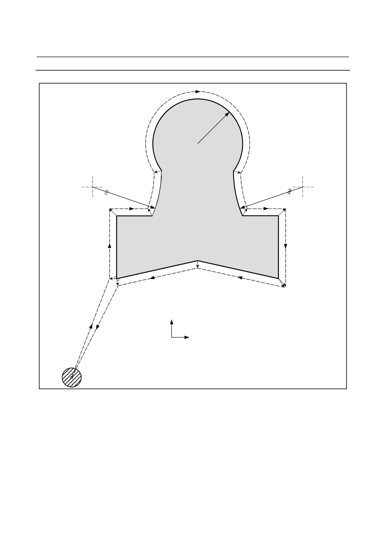
Example
250R
N5
C1(700,1300)
P4(500,1150) P5(900,1150)
C3
(-150,1150)
C2 (1550,1150)
650R
650R
N4
N6
N3
N7
P2
P3(450,900)
P6(950,900)
P7
(250,900)
(1150,900)
N8
N2
P9(700,650)
P1
P8
(250,550)
(1150,550)
N10
N9
Y axis
N1
N11
Unit : mm
X axis
Start point
- 151 -
6.COMPENSATION FUNCTION
PROGRAMMING
B-64304EN-2/01
G92 X0 Y0 Z0 ;
Specifies absolute coordinates.
The tool is positioned at the start point (X0, Y0, Z0).
N1 G90 G17 G00 G41 D07 X250.0 Y550.0 ;
Starts cutter compensation (start-up).
The tool is shifted to the left of the programmed path by
the distance specified in D07.
In other words the tool path is shifted by the radius of
the tool
(offset mode) because D07 is set to
15
beforehand (the radius of the tool is 15 mm).
N2 G01 Y900.0 F150 ;
Specifies machining from P1 to P2.
N3 X450.0 ;
Specifies machining from P2 to P3.
N4 G03 X500.0 Y1150.0 R650.0 ;
Specifies machining from P3 to P4.
N5 G02 X900.0 R-250.0 ;
Specifies machining from P4 to P5.
N6 G03 X950.0 Y900.0 R650.0 ;
Specifies machining from P5 to P6.
N7 G01 X1150.0 ;
Specifies machining from P6 to P7.
N8 Y550.0 ;
Specifies machining from P7 to P8.
N9 X700.0 Y650.0 ;
Specifies machining from P8 to P9.
N10 X250.0 Y550.0 ;
Specifies machining from P9 to P1.
N11 G00 G40 X0 Y0 ;
Cancels the offset mode.
The tool is returned to the start point (X0, Y0, Z0).
Notes
- Bit 2 (OFH) of parameter No.5001
If bit 2 (OFH) of parameter No. 5001 is set, cutter compensation takes
precedence over tool length compensation. Concrete explanations
follow:
If OFH = "0":
-
Processing is carried out properly according to a selected modal
state (G43, G44, or G49).
If OFH = "1":
-
In a block where G40, G41, or G42 is specified, tool length
compensation is disabled.
-
In the G40 mode, processing is carried out properly according to
a selected modal state (G43, G44, or G49).
-
In the G41 and G42 modes, tool length compensation is enabled
only in a block in which G43, G44, or G49 is specified. No
compensation amount is updated only with the H code.
G49 is enabled if G49 is specified in the same block as for G40,
however.
- 152 -
B-64304EN-2/01
PROGRAMMING
6.COMPENSATION FUNCTION
6.6
DETAILS OF CUTTER COMPENSATION
6.6.1
Overview
- Inner side and outer side
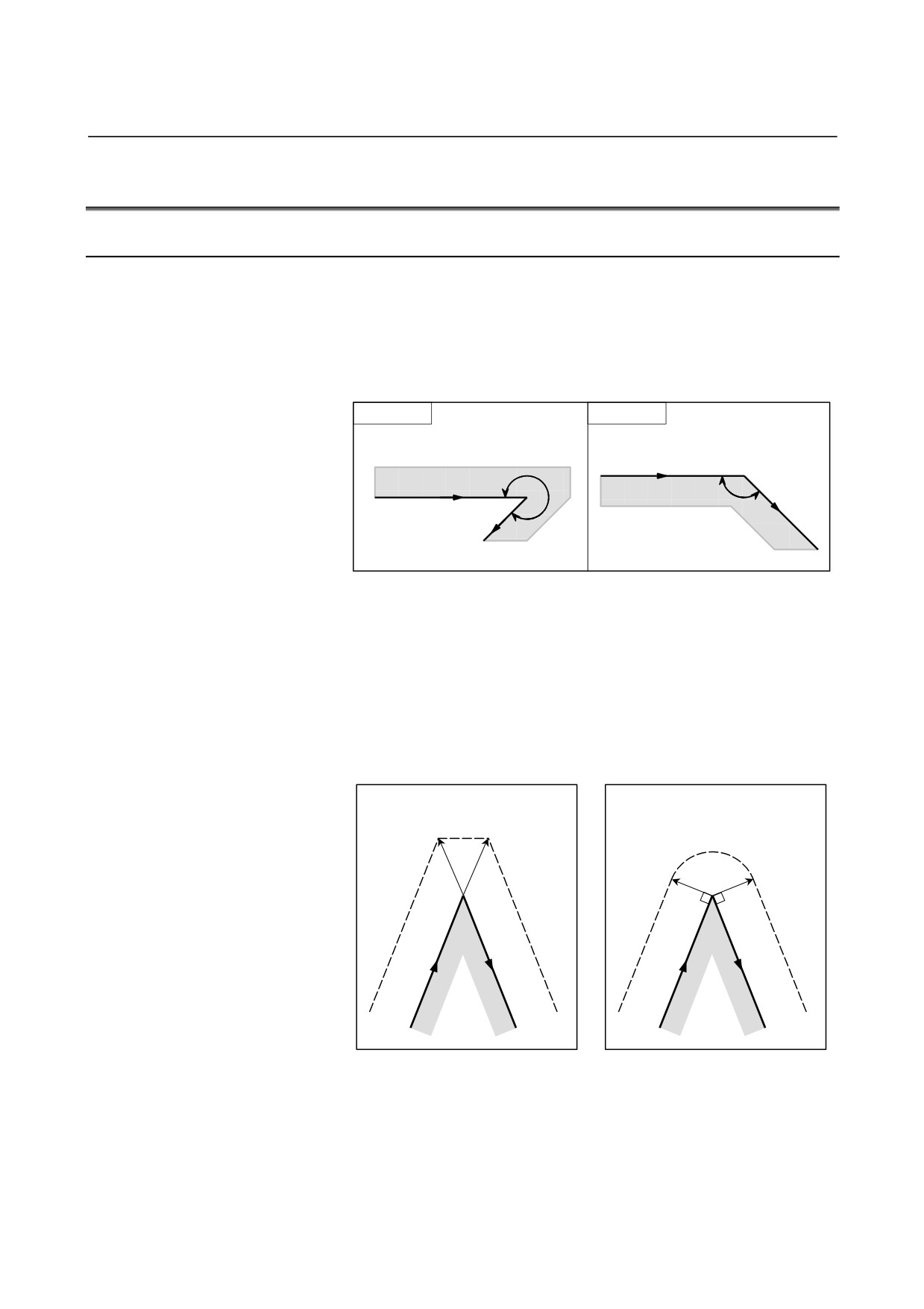
When an angle of intersection of the tool paths specified with move
commands for two blocks on the workpiece side is over 180°, it is
referred to as "inner side." When the angle is between 0° and 180°, it
is referred to as "outer side."
Inner side
Outer side
Programmed path
Workpiece
α
α
Workpiece
Programmed path
180°≤α
0°≤α<180°
- Outer corner connection method
If the tool moves around an outer corner in cutter compensation mode,
it is possible to specify whether to connect compensation vectors with
linear interpolation or with circular interpolation, using parameter
CCC (No. 19607#2).
<1> Linear connection type
<2> Circular connection type
[Bit 2 (CCC) of parameter
[Bit 2 (CCC) of
No.19607 = 0]
parameter No.19607 = 0]
Vectors are connected with linear
Vectors are connected with circular
interpolation.
interpolation.
- 153 -
6.COMPENSATION FUNCTION
PROGRAMMING
B-64304EN-2/01
- Cancel mode
The cutter compensation enters the cancel mode under the following
conditions.
(The system may not enter the cancel mode depending
on the machine tool.)
<1> Immediately after the power is turned on
<2> When the
key on the MDI panel is pushed
<3> After a program is forced to end by executing M02 or M30
<4> After the cutter compensation cancel command
(G40) is
exercised
In the cancel mode, the compensation vector is set to zero, and the
path of the center of tool coincides with the programmed path. A
program must end in cancel mode. If it ends in the cutter
compensation mode, the tool cannot be positioned at the end point,
and the tool stops at a location the compensation vector length away
from the end point.
NOTE
The operation to be performed when a reset operation
is performed during cutter compensation differs
depending on bit 6 (CLR) of parameter No. 3402.
- If CLR is 0
The system enters the reset state. G41/G42 are
retained as the modal code of group 07, but to
perform cutter compensation, an offset number (D
code) must be specified again.
- If CLR is 1
The system enters the clear state. The modal code
of group 07 is G40, and to perform cutter
compensation again, G41/G42 and an offset
number (D code) must be specified.
- Start-up
When a block which satisfies all the following conditions is executed
in cancel mode, the CNC enters the cutter compensation mode.
Control during this operation is called start-up.
<1> G41 or G42 is contained in the block, or has been specified to
place the CNC in the cutter compensation mode.
<2> 0 < compensation number of cutter compensation ≤ maximum
compensation number
<3> Positioning (G00) or linear interpolation (G01) mode
<4> A compensation plane axis command with a travel distance of 0
(except start-up type C) is specified.
If start-up is specified in circular interpolation
(G02, G03) mode,
PS0034 will occur.
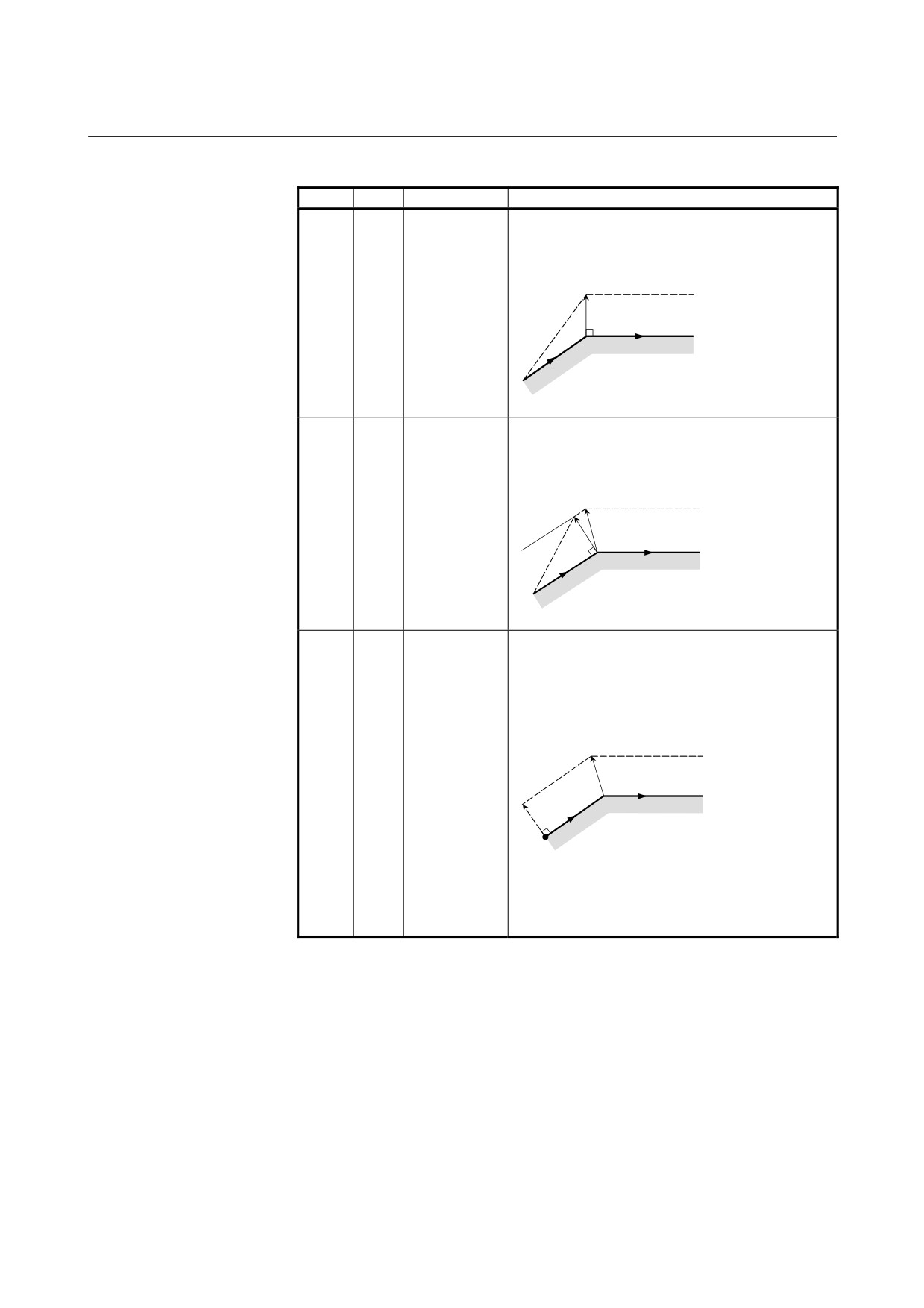
As a start-up operation, one of the three types A, B, and C can be
selected by setting parameter SUP (No. 5003#0) and parameter SUV
(No. 5003#1) appropriately. The operation to be performed if the
tool moves around an inner side is of single type only.
- 154 -
B-64304EN-2/01
PROGRAMMING
6.COMPENSATION FUNCTION
Table 6.6.1 (a) Start-up/cancel operation
SUV
SUP
Type
Operation
0
0
Type A
A compensation vector is output, which is vertical
to the block subsequent to the start-up block and
the block preceding the cancel block.
Tool center path
G41
Programmed path
N2
N1
0
1
Type B
A compensation vector is output, which is vertical
to the start-up block and the cancel block. An
intersection vector is also output.
Intersection
Tool center path
Programmed path
G41
N2
N1
1
0
Type C
When the start-up block and the cancel block are
1
blocks without tool movement, the tool moves by
the cutter compensation value in the direction
vertical to the block subsequent to the start-up
block and the block preceding the cancel block.
Intersection
Tool center path
Programmed path
Programmed
N3
path
G41
N2
N1
For a block with tool movement, the tool follows
the SUP setting: If it is 0, type A is assumed and
if 1, type B is assumed.
- Reading input commands in cutter compensation mode
In cutter compensation mode, input commands are read from usually
three blocks and up to eight blocks depending on the setting of
parameter
(No.
19625) to perform intersection calculation or an
interference check, described later, regardless of whether the blocks
are with or without tool movement, until a cancel command is
received.
To perform intersection calculation, it is necessary to read at least two
blocks with tool movement. To perform an interference check, it is
necessary to read at least three blocks with tool movement.
- 155 -
6.COMPENSATION FUNCTION
PROGRAMMING
B-64304EN-2/01
As the setting of parameter (No. 19625), that is, the number of blocks
to read, increases, it is possible to predict overcutting (interference)
for up to more subsequent commands. Increases in blocks to read
and analyze, however, cause reading and analysis to take more time.
- Ending (canceling) cutter compensation
In cutter compensation mode, cutter compensation is canceled if a
block that satisfies at least either one of the following conditions is
executed:
<1> G40 is specified.
<2> D00 is specified as the compensation number of cutter
compensation.
If cutter compensation cancel is to be performed, it must not be by a
circular command (G02, G03). Otherwise, an alarm will occur.
For a cancel operation, one of three types, A, B, and C, can be
selected by appropriately setting parameter SUP (No. 5003#0) and
parameter SUV (No. 5003#1). The operation to be performed if the
tool turns around the inside is of a single type.
- Meaning of symbols
The following symbols are used in subsequent figures:
• S indicates a position at which a single block is executed once.
• SS indicates a position at which a single block is executed twice.
• SSS indicates a position at which a single block is executed three
times.
• L indicates that the tool moves along a straight line.
• C indicates that the tool moves along an arc.
• r indicates the cutter compensation value.
• An intersection is a position at which the programmed paths of two
blocks intersect with each other after they are shifted by r.
•
indicates the center of the tool.
- 156 -
B-64304EN-2/01
PROGRAMMING
6.COMPENSATION FUNCTION
6.6.2
Tool Movement in Start-up
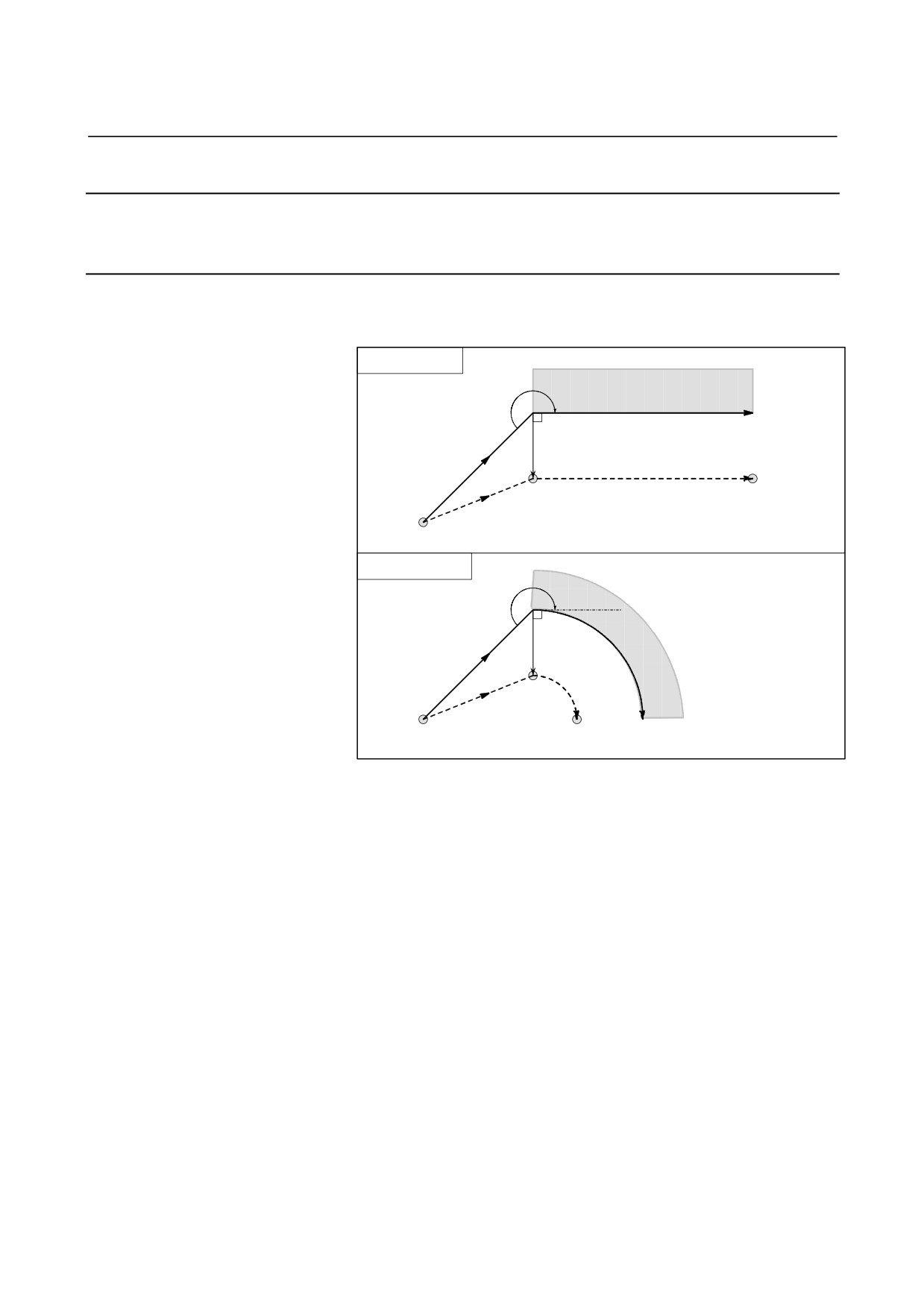
When the offset cancel mode is changed to offset mode, the tool
moves as illustrated below (start-up):
Explanation
- Tool movement around an inner side of a corner (180°≤ α)
Linear→Linear
α
Workpiece
Programmed path
r
G42
S
L
Tool center path
L
Start point
Linear→Circular
α
Work-
G42
piece
S
C
L
Start point
Tool center path Programmed path
- 157 -
6.COMPENSATION FUNCTION
PROGRAMMING
B-64304EN-2/01
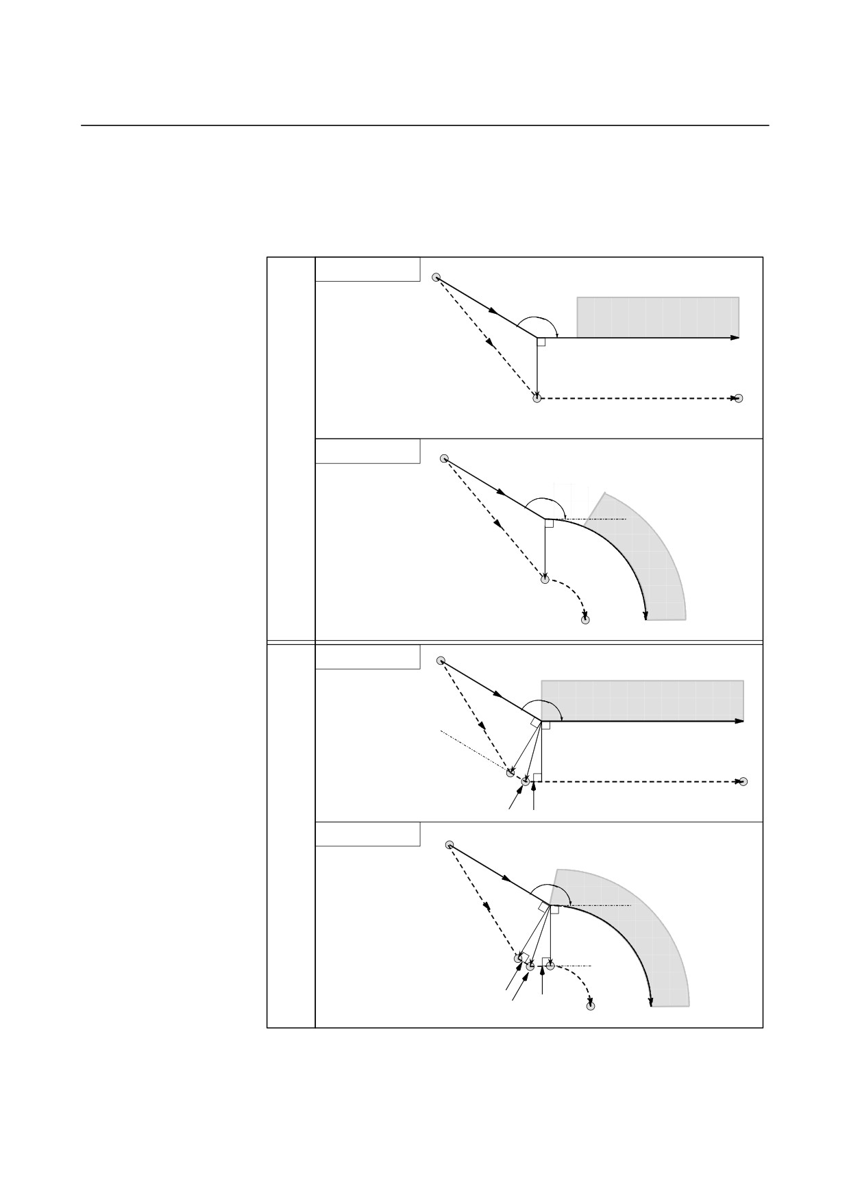
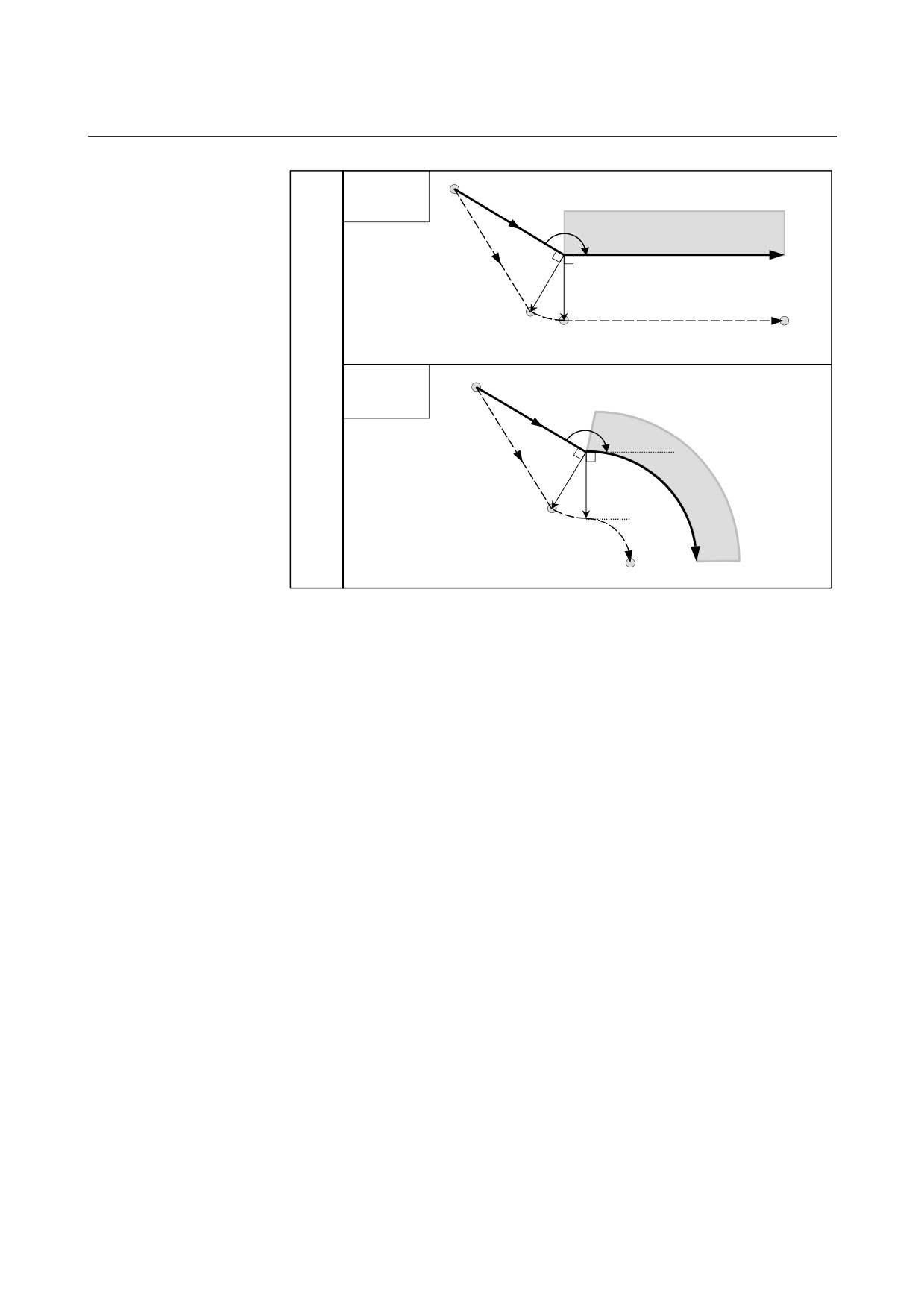
- Cases in which the start-up block is a block with tool movement and the tool
moves around the outside at an obtuse angle (90°≤ α<180°)
Tool path in start-up has two types A and B, and they are selected by
parameter SUP (No.5003#0).
Linear→Linear
Start point
G42
α
Workpiece
L
Programmed path
r
S
L
Tool center path
Type
A
Linear→Circular
Start point
G42
α
L
r
Work-
piece
e
S
Tool center path
Programmed path
Linear→Linear
(Linear connection type)
Start point
G42
α
Workpiece
L
Programmed path
r
r
L
S
Tool center path
Intersection
L
Type
Linear→Circular
B
Start point
(Linear connection type)
G42
α
L
r
ork-
r
ece
S
C
L
Intersection
th
Programmed path
- 158 -
B-64304EN-2/01
PROGRAMMING
6.COMPENSATION FUNCTION
Linear→Linear
Start point
(Circular
connection type)
G42
α
Workpiece
L
Programmed path
r
r
C
L
Tool center path
S
Type
B
Linear→Circular
Start point
(Circular
connection type)
G42
α
L
r
Workpiece
r
C
S
C
Tool center path Programmed path
- 159 -
6.COMPENSATION FUNCTION
PROGRAMMING
B-64304EN-2/01
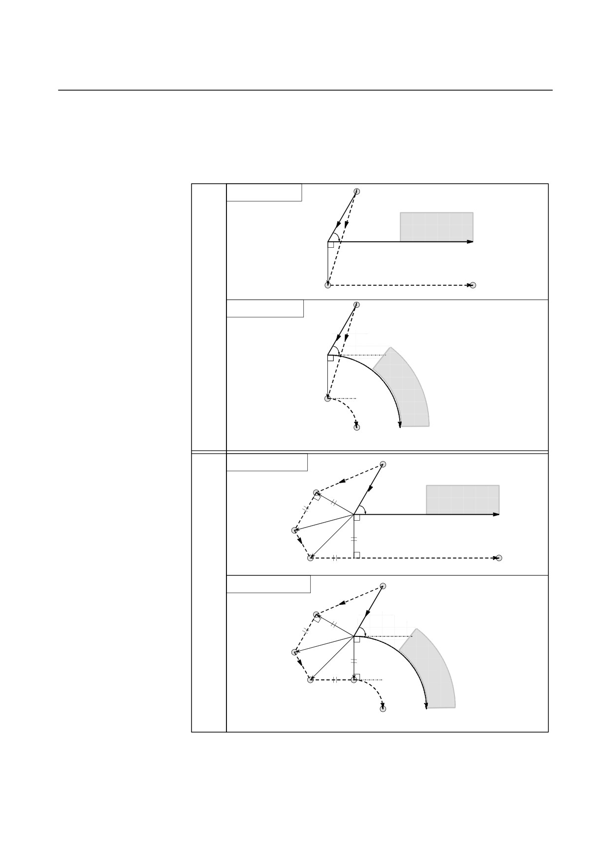
- Cases in which the start-up block is a block with tool movement and the tool
moves around the outside at an acute angle (α<90°)
Tool path in start-up has two types A and B, and they are selected by
parameter SUP (No.5003#0).
Linear→Linear
Start point
G42
Workpiece
α L
Programmed path
r
S
L
Tool center path
Type
A
Linear→Circular
Start point
G42
L
α
r
Work-
piece
S
C
Tool center path
Programmed path
Linear→Linear
Start point
(Linear connection type)
L
G42
Workpiece
r
α
L
Programmed path
r
L
S
L
L
Tool center path
Type
Linear→Circular
B
Start point
(Linear connection type)
L
G42
r
α
L
r
L
Work-
S
L
C
piece
Tool center path
Programmed path
- 160 -
B-64304EN-2/01
PROGRAMMING
6.COMPENSATION FUNCTION
Linear→Linear
Start point
(Circular
L
connection type)
G42
Workpiece
r
α
Programmed path
r
C
S
L
Tool center path
Type
B
Linear→Circular
Start point
(Circular
L
connection type)
G42
r
α
r
Work-
C
piece
S
C
Tool center path
Programmed path
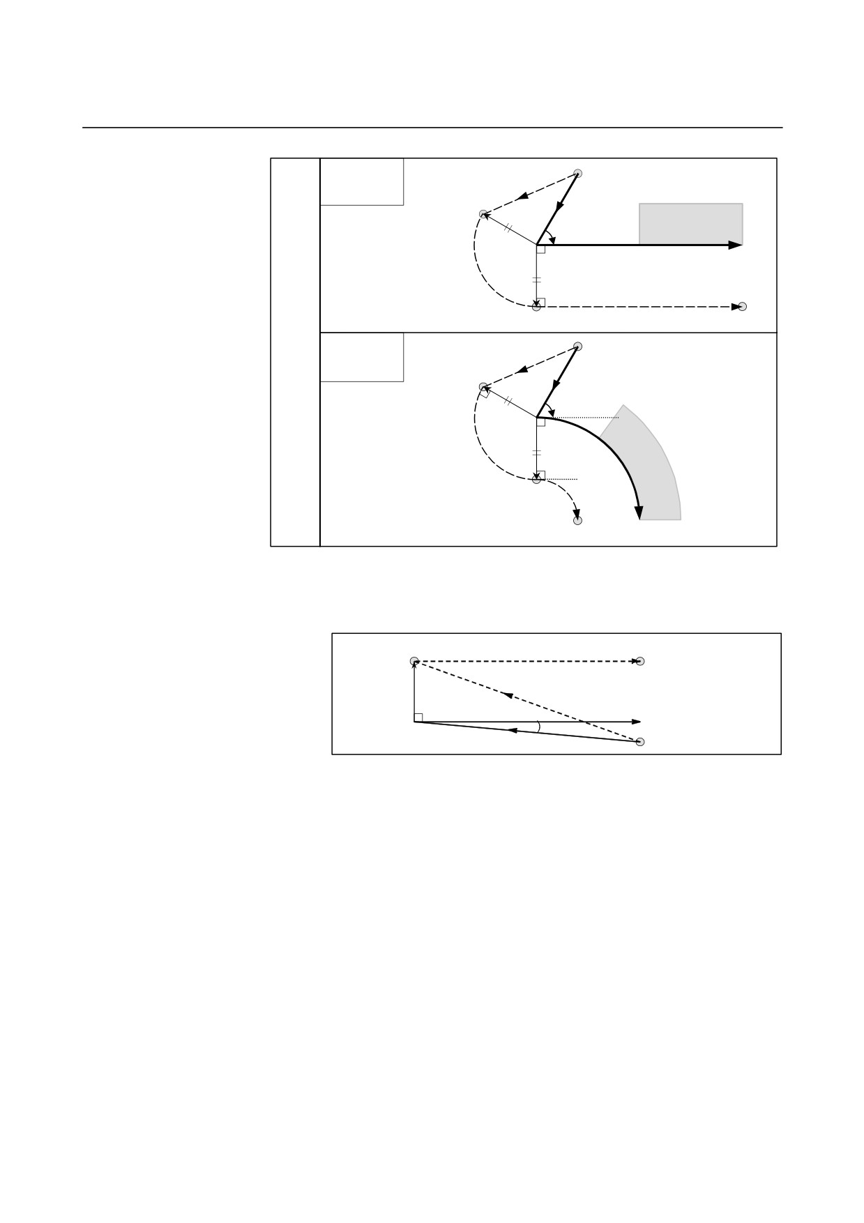
- Tool movement around the outside linear → linear at an acute angle less than 1
degree (α<1°)
S
Tool center path
L
L
r
Programmed path
(G41)
G41
Start point
Less than 1 deg
- 161 -
6.COMPENSATION FUNCTION
PROGRAMMING
B-64304EN-2/01
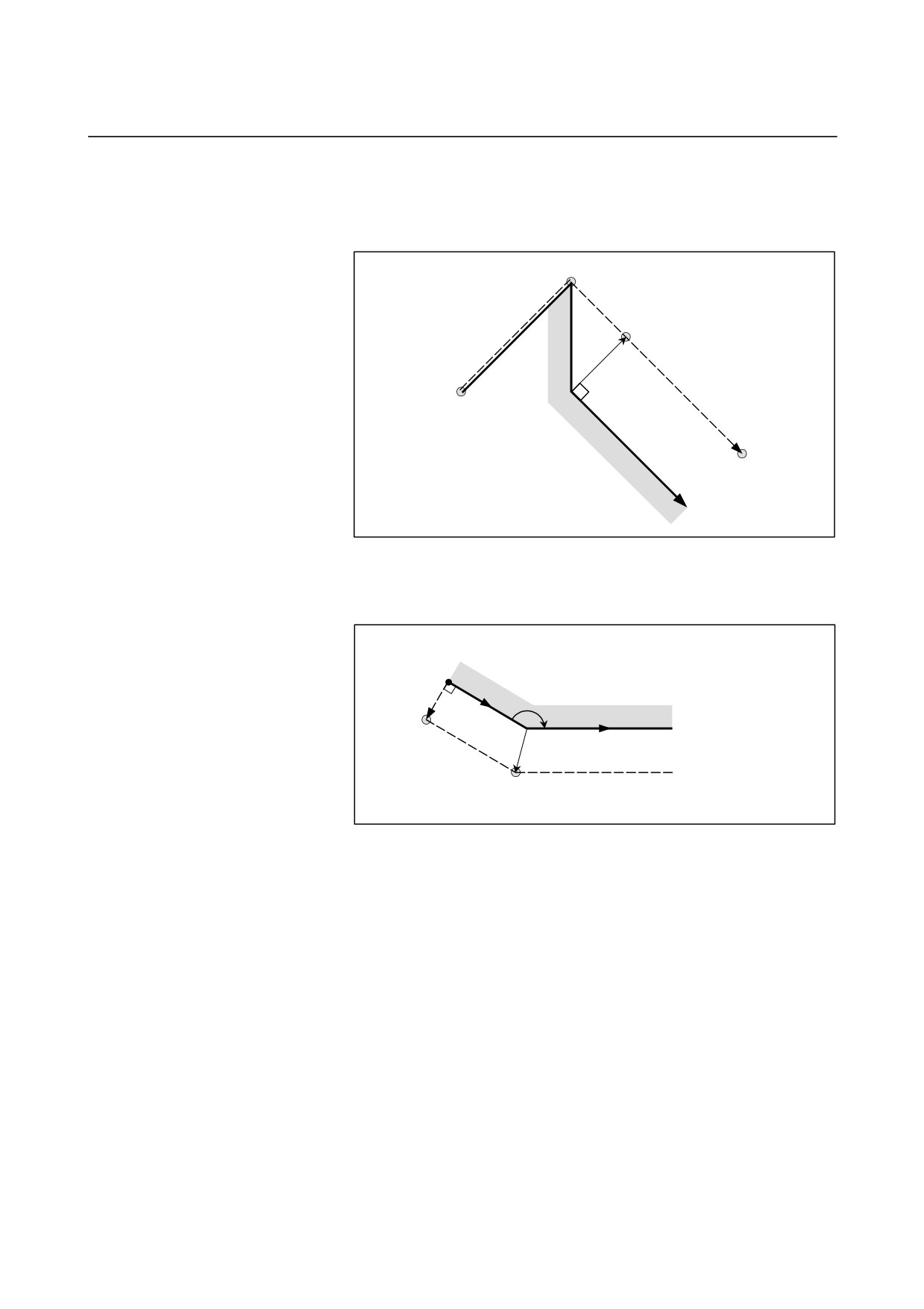
- A block without tool movement specified at start-up
For type A and B
If the command is specified at start-up, the offset vector is not
created. The tool does not operate in a start-up block.
SS
N7
S
N6
N8
r
Tool center path
G40 … ;
N9
N6 X100.0 Y100.0 ;
N7 G41 X0 ;
N8 Y-100.0 ;
N9 Y-100.0 X100.0 ;
Programmed path
For type C
The tool shifts by the compensation value in the direction vertical
to the block with tool movement subsequent to the start-up block.
Without tool
movement
L
α
S
Programmed path
L
Tool center path
S
Intersection
- 162 -
B-64304EN-2/01
PROGRAMMING
6.COMPENSATION FUNCTION
6.6.3
Tool Movement in Offset Mode
In offset mode, compensation is performed even for positioning
commands, not to speak of linear and circular interpolations. To
perform intersection calculation, it is necessary to read at least two
blocks with tool movement. If, therefore, two or more blocks with
tool movement cannot be read in offset mode because blocks without
tool movement, such as auxiliary function independent commands and
dwell, are specified in succession, excessive or insufficient cutting
may occur because intersection calculation fails. Assuming the
number of blocks to read in offset mode, which is determined by
parameter (No. 19625), to be N and the number of commands in those
N blocks without tool movement that have been read to be M, the
condition under which intersection calculation is possible is (N - 2) ≥
M. For example, if the maximum number of blocks to read in offset
mode is 5, intersection calculation is possible even if up to three
blocks without tool movement are specified.
NOTE
The condition necessary for an interference check,
described later, differs from this condition. For
details, see the explanation of the item,
“interference check.”
If a G or M code in which buffering is suppressed is specified, no
subsequent commands can be read before that block is executed,
regardless of the setting of parameter (No. 19625). Excessive or
insufficient cutting may, therefore, occur because of an intersection
calculation failure.
- 163 -
6.COMPENSATION FUNCTION
PROGRAMMING
B-64304EN-2/01
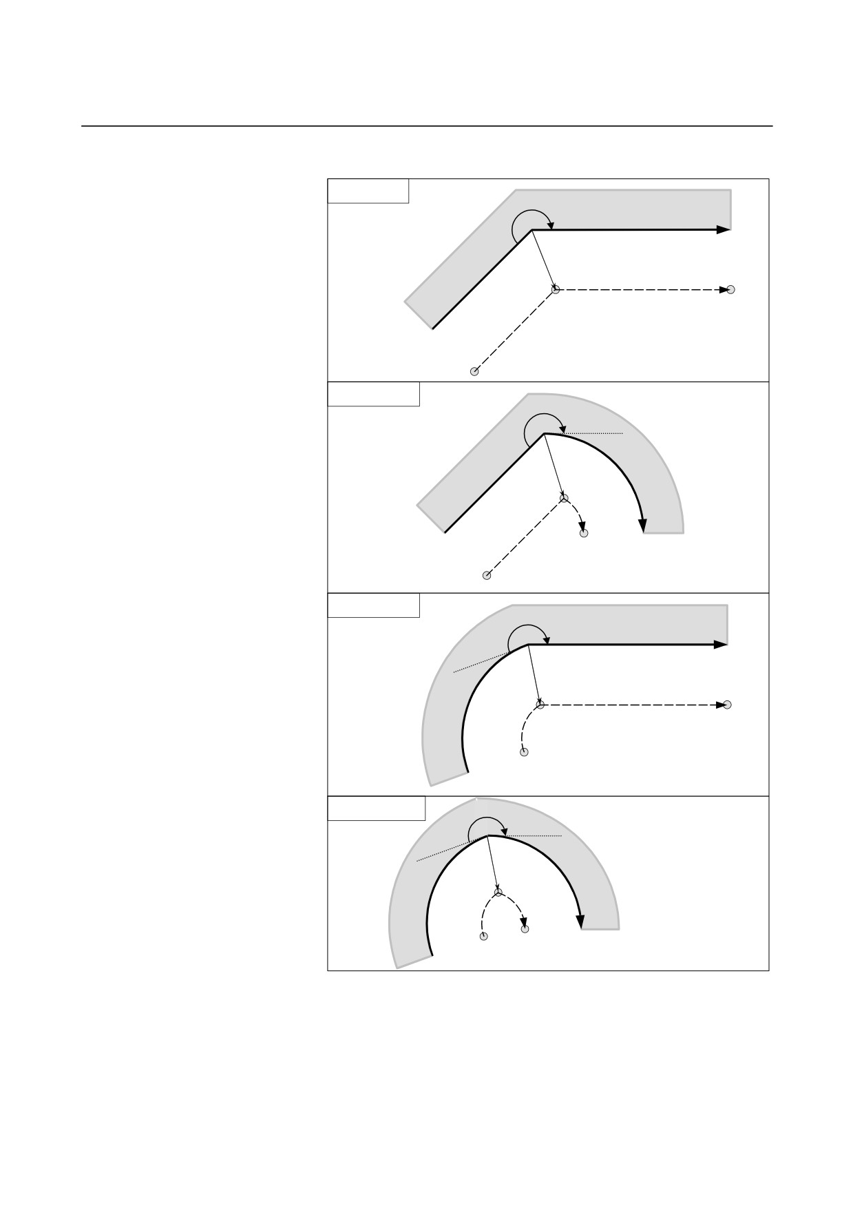
- Tool movement around the inside of a corner (180°≤ α)
Linear→Linear
α
Workpiece
Programmed path
S
L
Tool center path
Intersection
L
Linear→Circular
α
Work-
piece
Intersection
S
C
L
Tool center path
Programmed path
Circular→Linear
α
Workpiece
Programmed path
L
S
Tool center path
C Intersection
Circular→Circular
α
Work-
Intersection
piece
S
C
C
Tool center
Programmed path
path
- 164 -
B-64304EN-2/01
PROGRAMMING
6.COMPENSATION FUNCTION
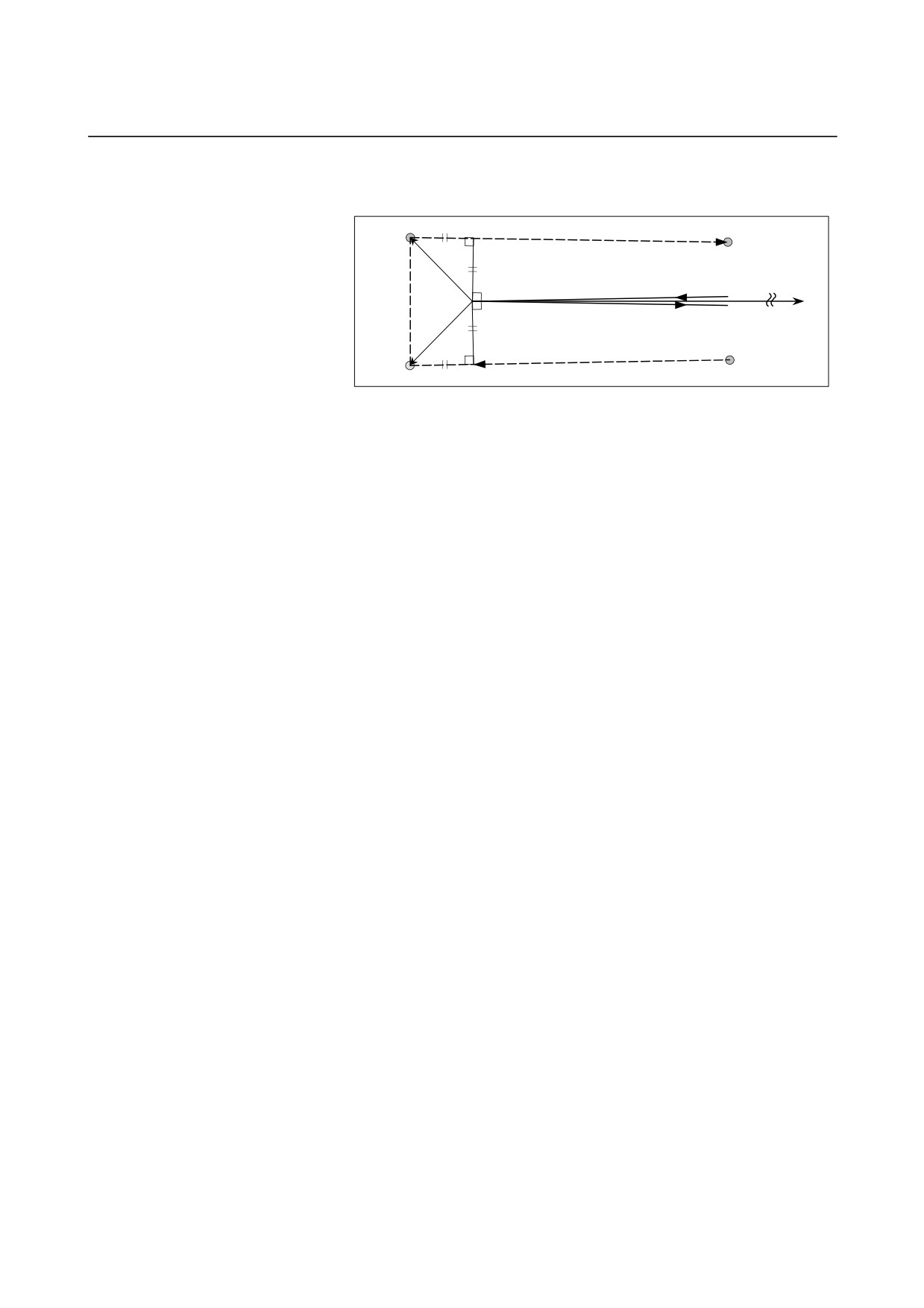
- Tool movement around the inside (α<1°) with an abnormally long vector, linear →
linear
Intersection
r
Tool center path
Programmed path
r
r
S
Intersection
Also in case of arc to straight line, straight line to arc and arc to arc,
the reader should infer in the same procedure.
- 165 -