FANUC Series 0i-MODEL D, Series 0i Mate-MODEL D. For Machining Center System USER’S MANUAL - page 4
5. FUNCTIONS TO SIMPLIFY
PROGRAMMING
PROGRAMMING
B-64304EN-2/01
- Rigid mode
Rigid mode can be specified using any of the following methods:
• Specify M29 S***** before a tapping command.
• Specify M29 S***** in a block which contains a tapping command.
• Specify G84 for rigid tapping (parameter G84 No. 5200 #0 set to 1).
- Thread lead
In feed-per-minute mode, the thread lead is obtained from the
expression, feedrate ÷ spindle speed. In feed-per-revolution mode,
the thread lead equals the feedrate speed.
- Tool length compensation
If a tool length compensation (G43, G44, or G49) is specified in the
canned cycle, the offset is applied at the time of positioning to point
R.
- Series 10/11 format command
Rigid tapping can be performed using Series 10/11 format commands.
The rigid tapping sequence (including data transfer to and from the
PMC), Limitation, and the like are the same as described in this
chapter.
- Acceleration/deceleration after interpolation
Linear or bell-shaped acceleration/deceleration can be applied.
- Look-ahead acceleration/deceleration before interpolation
Look-ahead acceleration/deceleration before interpolation is invalid.
- Override
Various types of override functions are invalid. The following
override functions can be enabled by setting corresponding
parameters:
•
Extraction override
•
Override signal
See “Override during Rigid Tapping” below for details.
- Dry run
Dry run can be executed also in G84 (G74). When dry run is
executed at the feedrate for the drilling axis in G84 (G74), tapping is
performed according to the feedrate. Note that the spindle speed
becomes faster at a higher dry run feedrate.
- Machine lock
Machine lock can be executed also in G84 (G74).
When G84 (G74) is executed in the machine lock state, the tool does
not move along the drilling axis. Therefore, the spindle does not also
rotate.
- 76 -
5.FUNCTIONS TO SIMPLIFY
B-64304EN-2/01
PROGRAMMING
PROGRAMMING
- Reset
When a reset is performed during rigid tapping, the rigid tapping
mode is canceled and the spindle motor enters the normal mode.
Note that the G84 (G74) mode is not canceled in this case when bit 6
(CLR) of parameter No. 3402 is set.
- Interlock
Interlock can also be applied in G84 (G74).
- Feed hold and single block
When bit 6 (FHD) of parameter No. 5200 is set to 0, feed hold and
single block are invalid in the G84 (G74) mode. When this bit is set
to 1, they are valid.
- Backlash compensation
In the rigid tapping mode, backlash compensation is applied to
compensate the lost motion when the spindle rotates clockwise or
counterclockwise. Set the amount of backlash in parameters Nos.
5321 to 5324.
Along the drilling axis, backlash compensation has been applied.
Limitation
- Axis switching
Before the drilling axis can be changed, the canned cycle must be
canceled. If the drilling axis is changed in rigid mode, alarm PS0206
is issued.
- S command
• If a speed higher than the maximum speed for the gear being used
is specified, alarm PS0200 is issued.
• When the rigid tapping canned cycle is cancelled, the S command
used for rigid tapping is cleared to S0.
- Distribution amount for the spindle
The maximum distribution amount is as follows
(displayed on
diagnosis display No. 451):
•
For a serial spindle:
32,767 pulses per 8 ms
This amount is changed according to the gear ratio setting for the
position coder or rigid tapping command. If a setting is made to
exceed the upper limit, alarm PS0202 is issued.
- F command
If a value exceeding the upper limit of cutting feedrate is specified,
alarm PS0011 is issued.
- 77 -

5. FUNCTIONS TO SIMPLIFY
PROGRAMMING
PROGRAMMING
B-64304EN-2/01
- Unit of F command
Metric input
Inch input
Remarks
Decimal point programming
G94
1 mm/min
0.01 inch/min
allowed
Decimal point programming
G95
0.01 mm/rev
0.0001 inch/rev
allowed
- M29
If an S command and axis movement are specified between M29 and
G84, alarm PS0203 is issued. If M29 is specified in a tapping cycle,
alarm PS0204 is issued.
- P
Specify P in a block that performs drilling. If P is specified in a
non-drilling block, it is not stored as modal data.
- Cancel
Do not specify a G code of the 01 group (G00 to G03) and G74 in a
single block. Otherwise, G74 will be canceled.
- Tool offset
In the canned cycle mode, tool offsets are ignored.
- Program restart
A program cannot be restarted during rigid tapping.
- Subprogram call
In the canned cycle mode, specify the subprogram call command
M98P_ in an independent block.
Example
Z-axis feedrate
1000 mm/min
Spindle speed
1000 min-1
Thread lead
1.0 mm
<Programming of feed per minute>
G94;
Specify a feed-per-minute command.
G00 X120.0 Y100.0 ;
Positioning
M29 S1000 ;
Rigid mode specification
G84 Z-100.0 R-20.0 F1000 ;
Rigid tapping
<Programming of feed per revolution>
G95 ;
Specify a feed-per-revolution command.
G00 X120.0 Y100.0 ;
Positioning
M29 S1000 ;
Rigid mode specification
G84 Z-100.0 R-20.0 F1.0 ;
Rigid tapping
- 78 -
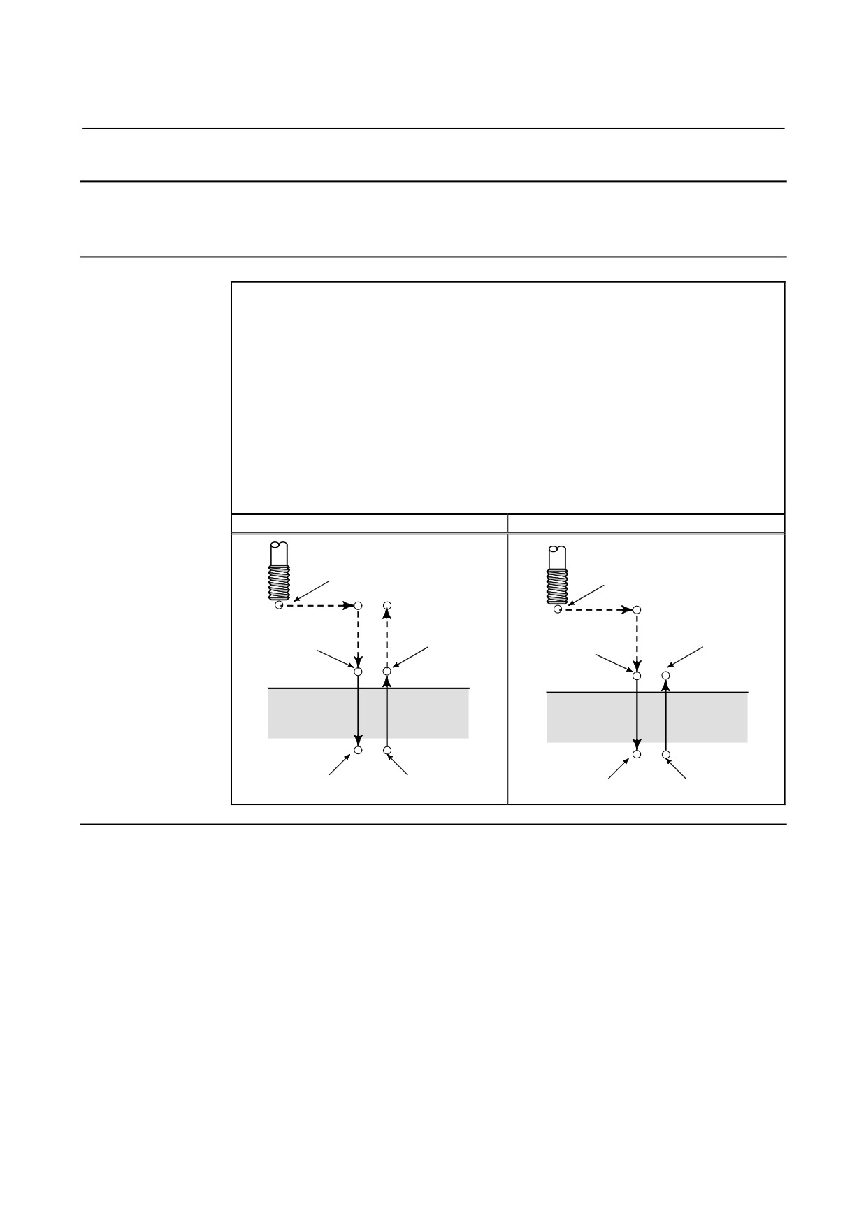
5.FUNCTIONS TO SIMPLIFY
B-64304EN-2/01
PROGRAMMING
PROGRAMMING
5.2.2
Left-Handed Rigid Tapping Cycle (G74)
When the spindle motor is controlled in rigid mode as if it were a
servo motor, tapping cycles can be speed up.
Format
G74 X_ Y_ Z_ R_ P_ F_ K_ ;
X_ Y_ : Hole position data
Z_
: The distance from point R to the bottom of the hole and the
position of the bottom of the hole
R_
: The distance from the initial level to point R level
P_
: Dwell time at the bottom of the hole and at point R when return is
made.
F_
: Cutting feedrate
K_
: Number of repeats (if required)
G84.3 X_ Y_ Z_ R_ P_ F_ L_ ;
(Series 10/11 format)
L_
: Number of repeats (if required)
G74 (G98)
G74 (G99)
Spindle stop
Spindle stop
Initial level
Operation 1
Operation 2
Operation 6
Spindle stop
Spindle CCW
Spindle CCW
Spindle
P
stop
P
Point R
Point R level
Point R
Point R level
Operation 3
Operation 5
Point Z
Point Z
P
P
Spindle stop
Spindle CW
Spindle stop
Spindle CW
Operation 4
Explanation
After positioning along the X- and Y-axes, rapid traverse is performed
to point R.
Tapping is performed from point R to point Z. When tapping is
completed, the spindle is stopped and a dwell is performed. The
spindle is then rotated in the normal direction, the tool is retracted to
point R, then the spindle is stopped. Rapid traverse to initial level is
then performed.
While tapping is being performed, the feedrate override and spindle
override are assumed to be 100%. Feedrate override can be enabled
by setting, however.
- 79 -
5. FUNCTIONS TO SIMPLIFY
PROGRAMMING
PROGRAMMING
B-64304EN-2/01
- Rigid mode
Rigid mode can be specified using any of the following methods:
•
Specify M29 S***** before a tapping command.
•
Specify M29 S***** in a block which contains a tapping
command.
•
Specify G74 for rigid tapping. (parameter G84 (No. 5200#0) set
to1).
- Thread lead
In feed-per-minute mode, the thread lead is obtained from the
expression, feedrate ÷ spindle speed. In feed-per-revolution mode,
the thread lead equals the feedrate.
- Tool length compensation
If a tool length compensation (G43, G44, or G49) is specified in the
canned cycle, the offset is applied at the time of positioning to point
R.
- Series 10/11 format command
Rigid tapping can be performed using Series 15 format commands.
The rigid tapping sequence (including data transfer to and from the
PMC), Limitation, and the like are the same as described in this
chapter.
- Acceleration/deceleration after interpolation
Linear or bell-shaped acceleration/deceleration can be applied.
- Look-ahead acceleration/deceleration before interpolation
Look-ahead acceleration/deceleration before interpolation is invalid.
- Override
Various types of override functions are invalid. The following
override functions can be enabled by setting corresponding
parameters:
• Extraction override
• Override signal
See “Override during Rigid Tapping” below for details.
- Dry run
Dry run can be executed also in G84 (G74). When dry run is
executed at the feedrate for the drilling axis in G84 (G74), tapping is
performed according to the feedrate. Note that the spindle speed
becomes faster at a higher dry run feedrate.
- Machine lock
Machine lock can be executed also in G84 (G74).
When G84 (G74) is executed in the machine lock state, the tool does
not move along the drilling axis. Therefore, the spindle does not also
rotate.
- 80 -

5.FUNCTIONS TO SIMPLIFY
B-64304EN-2/01
PROGRAMMING
PROGRAMMING
- Reset
When a reset is performed during rigid tapping, the rigid tapping
mode is canceled and the spindle motor enters the normal mode.
Note that the G84 (G74) mode is not canceled in this case when bit 6
(CLR) of parameter No. 3402 is set.
- Interlock
Interlock can also be applied in G84 (G74).
- Feed hold and single block
When bit 6 (FHD) of parameter No. 5200 is set to 0, feed hold and
single block are invalid in the G84 (G74) mode. When this bit is set
to 1, they are valid.
- Backlash compensation
In the rigid tapping mode, backlash compensation is applied to
compensate the lost motion when the spindle rotates clockwise or
counterclockwise. Set the amount of backlash in parameters Nos.
5321 to 5324.
Along the drilling axis, backlash compensation has been applied.
Limitation
- Axis switching
Before the drilling axis can be changed, the canned cycle must be
canceled. If the drilling axis is changed in rigid mode, alarm PS0206
is issued.
- S command
• Specifying a rotation speed exceeding the maximum speed for the
gear used causes alarm PS0200.
• When the rigid tapping canned cycle is cancelled, the S command
used for rigid tapping is cleared to S0.
- Distribution amount for the spindle
The maximum distribution amount is as follows
(displayed on
diagnosis display No. 451):
• For a serial spindle:
32,767 pulses per 8 ms
This amount is changed according to the gear ratio setting for the
position coder or rigid tapping command. If a setting is made to
exceed the upper limit, alarm PS0202 is issued.
- F command
Specifying a value that exceeds the upper limit of cutting feedrate
causes alarm PS0011.
- Unit of F command
Metric input
Inch input
Remarks
G94
1 mm/min
0.01 inch/min
Decimal point programming allowed
G95
0.01 mm/rev
0.0001 inch/rev
Decimal point programming allowed
- 81 -
5. FUNCTIONS TO SIMPLIFY
PROGRAMMING
PROGRAMMING
B-64304EN-2/01
- M29
Specifying an S command or axis movement between M29 and G84
causes alarm PS0203.
Then, specifying M29 in the tapping cycle causes alarm PS0204.
- P
Specify P in a block that performs drilling. If P is specified in a
non-drilling block, it is not stored as modal data.
- Cancel
Do not specify a G code of the 01 group (G00 to G03) and G74 in a
single block. Otherwise, G74 will be canceled.
- Tool offset
In the canned cycle mode, tool offsets are ignored.
- Subprogram call
In the canned cycle mode, specify the subprogram call command
M98P_ in an independent block.
Example
Z-axis feedrate
1000 mm/min
Spindle speed
1000 min-1
Thread lead
1.0 mm
<Programming for feed per minute>
G94 ;
Specify a feed-per-minute command.
G00 X120.0 Y100.0 ;
Positioning
M29 S1000 ;
Rigid mode specification
G74 Z-100.0 R-20.0 F1000 ;
Rigid tapping
<Programming for feed per revolution>
G95 ;
Specify a feed-per-revolution command.
G00 X120.0 Y100.0 ;
Positioning
M29 S1000 ;
Rigid mode specification
G74 Z-100.0 R-20.0 F1.0 ;
Rigid tapping
- 82 -
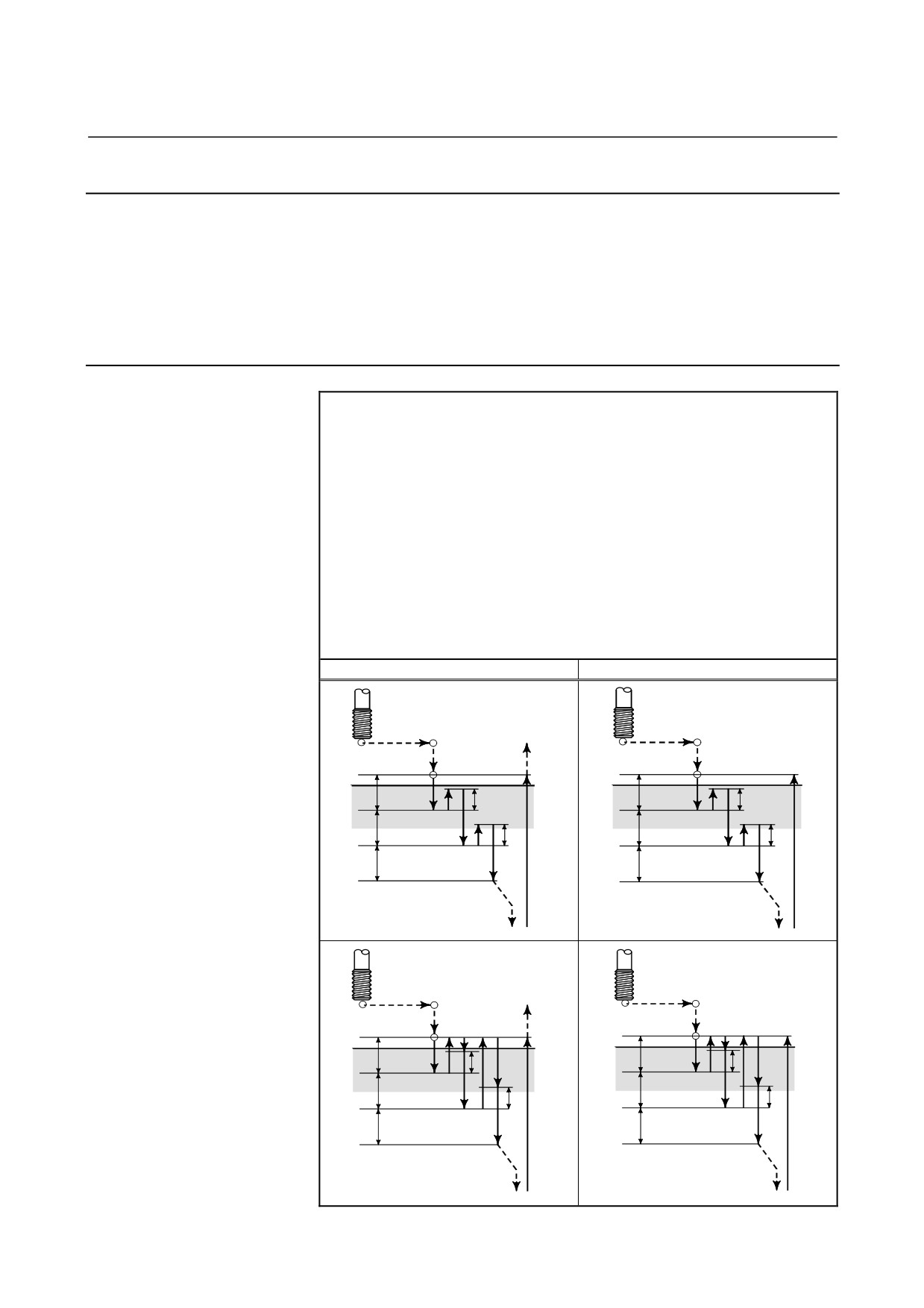
5.FUNCTIONS TO SIMPLIFY
B-64304EN-2/01
PROGRAMMING
PROGRAMMING
5.2.3
Peck Rigid Tapping Cycle (G84 or G74)
Tapping a deep hole in rigid tapping mode may be difficult due to
chips sticking to the tool or increased cutting resistance. In such
cases, the peck rigid tapping cycle is useful.
In this cycle, cutting is performed several times until the bottom of the
hole is reached.
Two peck tapping cycles are available:
High-speed peck tapping cycle and standard peck tapping cycle.
These cycles are selected using the PCP bit (bit 5) of parameter 5200.
Format
G84 (or G74) X_ Y_ Z_ R_ P_ Q_ F_ K_ ;
X_ Y_ : Hole position data
Z_
: The distance from point R to the bottom of the hole and
the position of the bottom of the hole
R_
: The distance from the initial level to point R level
P_
: Dwell time at the bottom of the hole and at point R when
a return is made
Q_
: Depth of cut for each cutting feed
F_
: The cutting feedrate
K_
: Number of repeats (if required)
G84.2 (or G84.3) X_ Y_ Z_ R_ P_ Q_ F_ L_ ;
(Series 10・11 format)
L_
: Number of repeats (if required)
G84, G74 (G98)
G84, G74 (G99)
• High-speed peck tapping cycle
d = retraction distance
(Parameter
PCP(No.5200#5)=0)
Initial level
<1> The tool operates at a
normal cutting feedrate.
Point R
Point R level
Point R
Point R level
The normal time constant
<1>
<1>
q
q
is used.
<2>
d
<2>
d
<2> Retraction can be
q
q
overridden.
d
d
The retraction time
q
q
constant is used.
Point Z
Point Z
• Peck tapping cycle (Parameter
d = cutting start distance
PCP(No.5200#5)=1)
<1> The tool operates at a
Initial level
normal cutting feedrate.
The normal time constant is
Point R
Point R level
Point R
Point R level
<3>
<3>
used.
‡
‡
<1>
<1>
q
q
<2> Retraction can be
<2>
d
<2>
d
overridden.
q
q
d
d
The retraction time constant
is used.
q
q
<3> Retraction can be
overridden.
The normal time constant is
Point Z
Point Z
used.
- 83 -
5. FUNCTIONS TO SIMPLIFY
PROGRAMMING
PROGRAMMING
B-64304EN-2/01
Explanation
- High-speed peck tapping cycle
After positioning along the X- and Y-axes, rapid traverse is performed
to point R. From point R, cutting is performed with depth Q (depth
of cut for each cutting feed), then the tool is retracted by distance d.
The DOV bit (bit 4) of parameter 5200 specifies whether retraction
can be overridden or not. When point Z has been reached, the
spindle is stopped, then rotated in the reverse direction for retraction.
Set the retraction distance, d, in parameter 5213.
- Peck tapping cycle
After positioning along the X- and Y-axes, rapid traverse is performed
to point R level. From point R, cutting is performed with depth Q
(depth of cut for each cutting feed), then a return is performed to point
R. The DOV bit (bit 4) of parameter 5200 specifies whether the
retraction can be overridden or not. The moving of cutting feedrate
F is performed from point R to a position distance d from the end
point of the last cutting, which is where cutting is restarted. For this
moving of cutting feedrate F, the specification of the DOV bit (bit 4)
of parameter 5200 is also valid. When point Z has been reached, the
spindle is stopped, then rotated in the reverse direction for retraction.
Set d (distance to the point at which cutting is started) in parameter
5213.
- Acceleration/deceleration after interpolation
Linear or bell-shaped acceleration/deceleration can be applied.
- Look-ahead acceleration/deceleration before interpolation
Look-ahead acceleration/deceleration before interpolation is invalid.
- Override
Various types of override functions are invalid. The following
override functions can be enabled by setting corresponding
parameters:
• Extraction override
• Override signal
See “Override during Rigid Tapping” below for details.
- Dry run
Dry run can be executed also in G84 (G74). When dry run is
executed at the feedrate for the drilling axis in G84 (G74), tapping is
performed according to the feedrate. Note that the spindle speed
becomes faster at a higher dry run feedrate.
- Machine lock
Machine lock can be executed also in G84 (G74).
When G84 (G74) is executed in the machine lock state, the tool does
not move along the drilling axis. Therefore, the spindle does not also
rotate.
- 84 -

5.FUNCTIONS TO SIMPLIFY
B-64304EN-2/01
PROGRAMMING
PROGRAMMING
- Reset
When a reset is performed during rigid tapping, the rigid tapping
mode is canceled and the spindle motor enters the normal mode.
Note that the G84 (G74) mode is not canceled in this case when bit 6
(CLR) of parameter No. 3402 is set.
- Interlock
Interlock can also be applied in G84 (G74).
- Feed hold and single block
When bit 6 (FHD) of parameter No. 5200 is set to 0, feed hold and
single block are invalid in the G84 (G74) mode. When this bit is set
to 1, they are valid.
- Backlash compensation
In the rigid tapping mode, backlash compensation is applied to
compensate the lost motion when the spindle rotates clockwise or
counterclockwise. Set the amount of backlash in parameters Nos.
5321 to 5324.
Along the drilling axis, backlash compensation has been applied.
Limitation
- Axis switching
Before the drilling axis can be changed, the canned cycle must be
canceled. If the drilling axis is changed in rigid mode, alarm PS0206
is issued.
- S command
• Specifying a rotation speed exceeding the maximum speed for the
gear used causes alarm PS0200.
• When the rigid tapping canned cycle is cancelled, the S command
used for rigid tapping is cleared to S0.
- Distribution amount for the spindle
The maximum distribution amount is as follows
(displayed on
diagnosis display No. 451):
• For a serial spindle:
32,767 pulses per 8 ms
This amount is changed according to the gear ratio setting for the
position coder or rigid tapping command. If a setting is made to
exceed the upper limit, alarm PS0202 is issued.
- F command
Specifying a value that exceeds the upper limit of cutting feedrate
causes alarm PS0011.
- Unit of F command
Metric input
Inch input
Remarks
G94
1 mm/min
0.01 inch/min
Decimal point programming allowed
G95
0.01 mm/rev
0.0001 inch/rev
Decimal point programming allowed
- 85 -
5. FUNCTIONS TO SIMPLIFY
PROGRAMMING
PROGRAMMING
B-64304EN-2/01
- M29
Specifying an S command or axis movement between M29 and G84
causes alarm PS0203.
Then, specifying M29 in the tapping cycle causes alarm PS0204.
- P/Q
Specify P and Q in a block that performs drilling. If they are
specified in a block that does not perform drilling, they are not stored
as modal data.
When Q0 is specified, the peck rigid tapping cycle is not performed.
- Cancel
Do not specify a group 01 G code (G00 to G03) and G84 in the same
block. If they are specified together, G84 is canceled.
- Tool offset
In the canned cycle mode, tool offsets are ignored.
- Subprogram call
In the canned cycle mode, specify the subprogram call command
M98P_ in an independent block.
- d (parameter No.5213)
Perform operation in the peck tapping cycle within point R. That is,
set a value which does not exceed point R for d (parameter No. 5213).
5.2.4
Canned Cycle Cancel (G80)
The rigid tapping canned cycle is canceled. For how to cancel this
cycle, see the Subsection 5.1.14, "Canned Cycle Cancel for Drilling
(G80)."
NOTE
When the rigid tapping canned cycle is cancelled,
the S value used for rigid tapping is also cleared
(as if S0 is specified).
Accordingly, the S command specified for rigid
tapping cannot be used in a subsequent part of the
program after the cancellation of the rigid tapping
canned cycle.
After canceling the rigid tapping canned cycle,
specify a new S command as required.
- 86 -
5.FUNCTIONS TO SIMPLIFY
B-64304EN-2/01
PROGRAMMING
PROGRAMMING
5.2.5
Override during Rigid Tapping
Various types of override functions are invalid. The following
override functions can be enabled by setting corresponding
parameters:
•
Extraction override
•
Override signal
5.2.5.1 Extraction override
For extraction override, the fixed override set in the parameter or
override specified in a program can be enabled at extraction (including
retraction during peck drilling/high-speed peck drilling).
Explanation
- Specifying the override in the parameter
Set bit 4 (DOV) of parameter No. 5200 to 1 and set the override in
parameter No. 5211.
An override from 0% to 200% in 1% steps can be set. Bit 3 (OVU)
of parameter No. 5201 can be set to 1 to set an override from 0% to
2000% in 10% steps.
- Specifying the override in a program
Set bit 4 (DOV) of parameter No. 5200 and bit 4 (OV3) of parameter
No. 5201 to 1. The spindle speed at extraction can be specified in
the program.
Specify the spindle speed at extraction using address "J" in the block
in which rigid tapping is specified.
Example) To specify 1000 min-1 for S at cutting and 2000 min-1 for S
at extraction
M29 S1000 ;
G84 Z-100. F1000. J2000 ;
The difference in the spindle speed is converted to the actual override
by the following calculation.
Therefore, the spindle speed at extraction may not be the same as that
specified at address "J". If the override does not fall in the range
between 100% and 200%, it is assumed to be 100%.
Spindle speed at extraction (specified at
J)
Override (% )
=
×
100
Spindle speed (specified at
S
)
Bit 6 (OVE) of parameter No. 5202 can be set to 1 to extend the
override value to 100% to 2000%. If the specified override value is
outside the range between 100% and 2000%, it is assumed to be
100%.
- 87 -
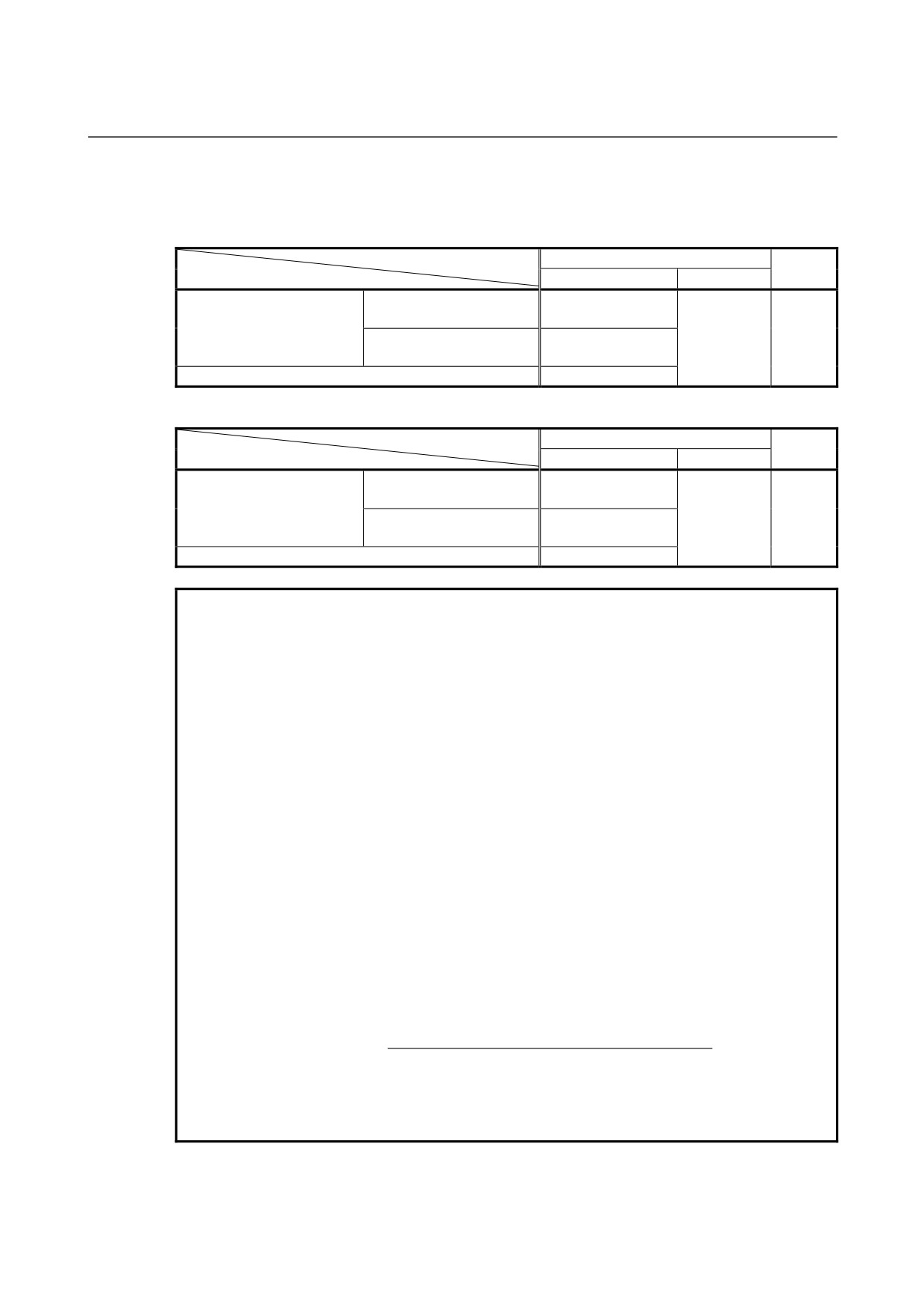
5. FUNCTIONS TO SIMPLIFY
PROGRAMMING
PROGRAMMING
B-64304EN-2/01
The override to be applied is determined according to the setting of
parameters and that in the command as shown in the table below.
When bit 6 (OVE) of parameter No. 5202 is set to 0
Parameter setting
DOV = 1
DOV = 0
Command
OV3 = 1
OV3 = 0
Within the range between
Command in the
Spindle speed at extraction
100% to 200%
program
Parameter
specified at address "J"
Outside the range between
100%
100%
No. 5211
100% to 200%
No spindle speed at extraction specified at address "J"
Parameter No. 5211
When bit 6 (OVE) of parameter No. 5202 is set to 1
Parameter setting
DOV = 1
DOV = 0
Command
OV3 = 1
OV3 = 0
Within the range between
Command in the
Spindle speed at extraction
100% to 2000%
program
Parameter
specified at address "J"
Outside the range between
100%
100%
No. 5211
100% to 2000%
No spindle speed at extraction specified at address "J"
Parameter No. 5211
NOTE
1
Do not use a decimal point in the value specified at address "J".
If a decimal point is used, the value is assumed as follows:
Example) When the increment system for the reference axis is IS-B
• When pocket calculator type decimal point programming is not used
The specified value is converted to the value for which the least
input increment is considered.
"J200." is assumed to be 200000 min-1.
• When pocket calculator type decimal point programming is used
The specified value is converted to the value obtained by rounding
down to an integer.
"J200." is assumed to be 200 min-1.
2
Do not use a minus sign in the value specified at address "J".
If a minus sign is used, a value outside the range is assumed to be
specified.
3
The maximum override is obtained using the following equation so that
the spindle speed to which override at extraction is applied do not
exceed the maximum used gear speed (specified in parameters Nos.
5241 to 5243). For this reason, the obtained value is not the same as
the maximum spindle speed depending on the override.
Maximum spindle speed (specified in
parameters
)
Maximum override (%)
=
×
100
Spindle speed (specified at
S
)
4
When a value is specified at address "J" for specifying the spindle speed
at extraction in the rigid tapping mode, it is valid until the canned cycle is
canceled.
- 88 -
5.FUNCTIONS TO SIMPLIFY
B-64304EN-2/01
PROGRAMMING
PROGRAMMING
5.2.5.2
Override signal
By setting bit 4 (OVS) of parameter No. 5203 to 1, override can be
applied to cutting/extraction operation during rigid tapping as follows:
•
Applying override using the feedrate override signal
•
Canceling override using the override cancel signal
There are the following relationships between this function and
override to each operation:
•
At cutting
-
When the override cancel signal is set to 0
Value specified by the override signal
-
When the override cancel signal is set to 1
100%
•
At extraction
-
When the override cancel signal is set to 0
Value specified by the override signal
-
When the override cancel signal is set to 1 and extraction
override is disabled
100%
-
When the override cancel signal is set to 1 and extraction
override is enabled
Value specified for extraction override
NOTE
1 The maximum override is obtained using the following equation so
that the spindle speed to which override is applied do not exceed the
maximum used gear speed (specified in parameters Nos. 5241 to
5243). For this reason, the obtained value is not the same as the
maximum spindle speed depending on the override.
Maximum spindle speed (specified in
parameters
)
Maximum override (%)
=
×
100
Spindle speed (specified at
S
)
2 Since override operation differs depending on the machine in use,
refer to the manual provided by the machine tool builder.
- 89 -
5. FUNCTIONS TO SIMPLIFY
PROGRAMMING
PROGRAMMING
B-64304EN-2/01
5.3
OPTIONAL CHAMFERING AND CORNER R
Overview
Chamfering and corner R blocks can be inserted automatically
between the following:
•
Between linear interpolation and linear interpolation blocks
•
Between linear interpolation and circular interpolation blocks
•
Between circular interpolation and linear interpolation blocks
•
Between circular interpolation and circular interpolation blocks
Format
, C_ Chamfering
, R_ Corner R
Explanation
When the above specification is added to the end of a block that
specifies linear interpolation (G01) or circular interpolation (G02 or
G03), a chamfering or corner R block is inserted.
Blocks specifying chamfering and corner R can be specified
consecutively.
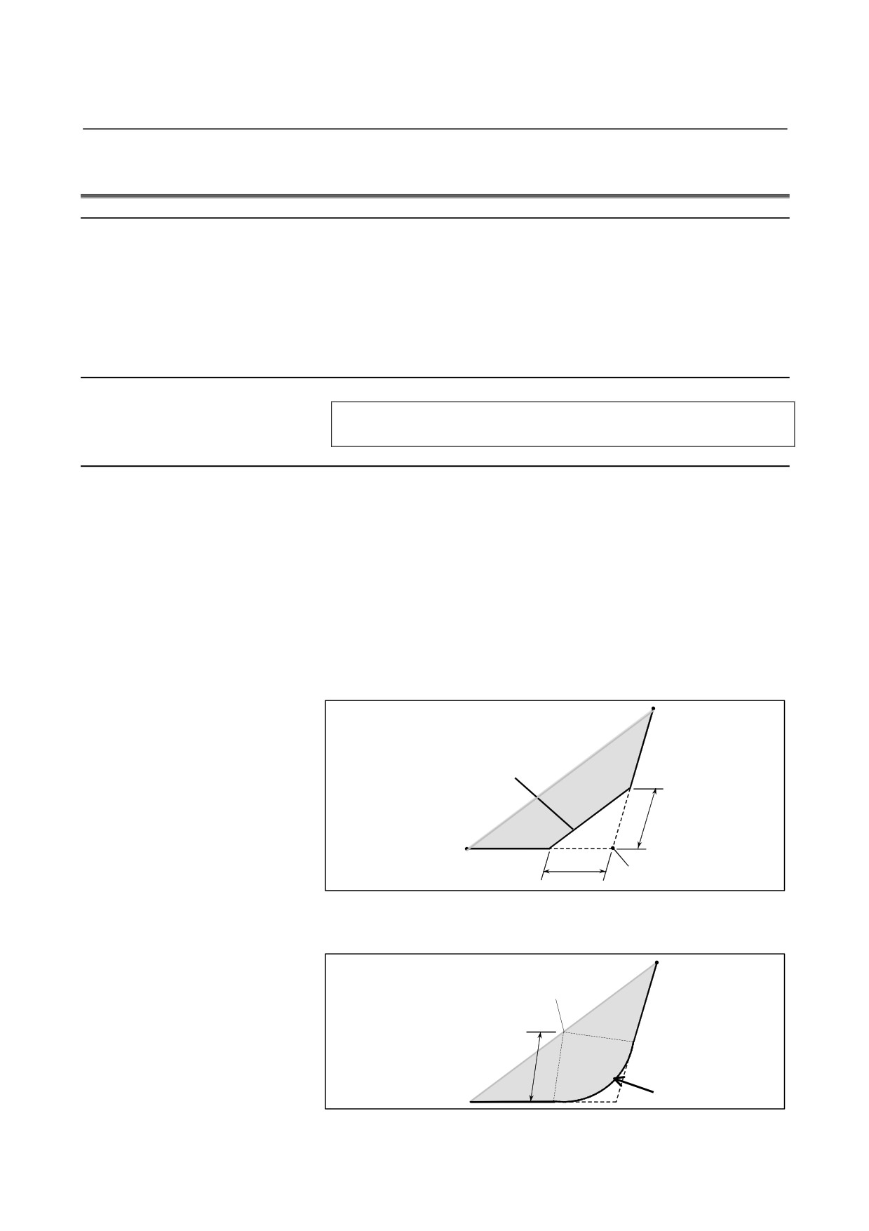
- Chamfering
After C, specify the distance from the hypothetical corner intersection
to the start and end points. The hypothetical corner point is the
corner point that would exist if chamfering were not performed.
<1> G91 G01 X100.0 ,C10.0 ;
<2> X100.0 Y100.0 ;
Inserted chamfering block
C
C
Hypothetical corner intersection
- Corner R
After R, specify the radius for corner R.
<1> G91 G01 X100.0 ,R10.0 ;
<2> X100.0 Y100.0 ;
Center of a circle with radius R
R
Inserted corner R
block
- 90 -
5.FUNCTIONS TO SIMPLIFY
B-64304EN-2/01
PROGRAMMING
PROGRAMMING
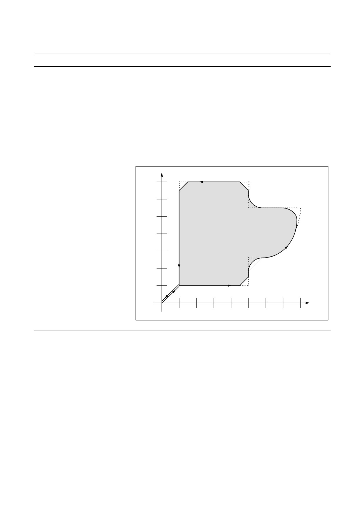
Example
N001 G92 G90 X0 Y0 ;
N002 G00 X10.0 Y10.0 ;
N003 G01 X50.0 F10.0 ,C5.0 ;
N004 Y25.0 ,R8.0 ;
N005 G03 X80.0 Y50.0 R30.0 ,R8.0 ;
N006 G01 X50.0 ,R8.0 ;
N007 Y70.0 ,C5.0 ;
N008 X10.0 ,C5.0 ;
N009 Y10.0 ;
N010 G00 X0 Y0 ;
N011 M0;
Y
N008
70.0
N007
60.0
N006
50.0
40.0
N009
N005
30.0
20.0
N004
10.0
N003
N010
N002
N011
0
N001
X
10.0
20.0
30.0
40.0
50.0
60.0
70.0
80.0
Limitation
- Invalid specification
Chamfering (,C) or corner R (,R) specified in a block other than a
linear interpolation (G01) or circular interpolation (G02 or G03) block
is ignored.
- Next block
A block specifying chamfering or corner R must be followed by a
block that specifies a move command using linear interpolation (G01)
or circular interpolation (G02 or G03). If the next block does not
contain these specifications, alarm PS0051 is issued.
Between these blocks, however, only one block specifying G04
(dwell) can be inserted. The dwell is executed after execution of the
inserted chamfering or corner R block.
- 91 -
5. FUNCTIONS TO SIMPLIFY
PROGRAMMING
PROGRAMMING
B-64304EN-2/01
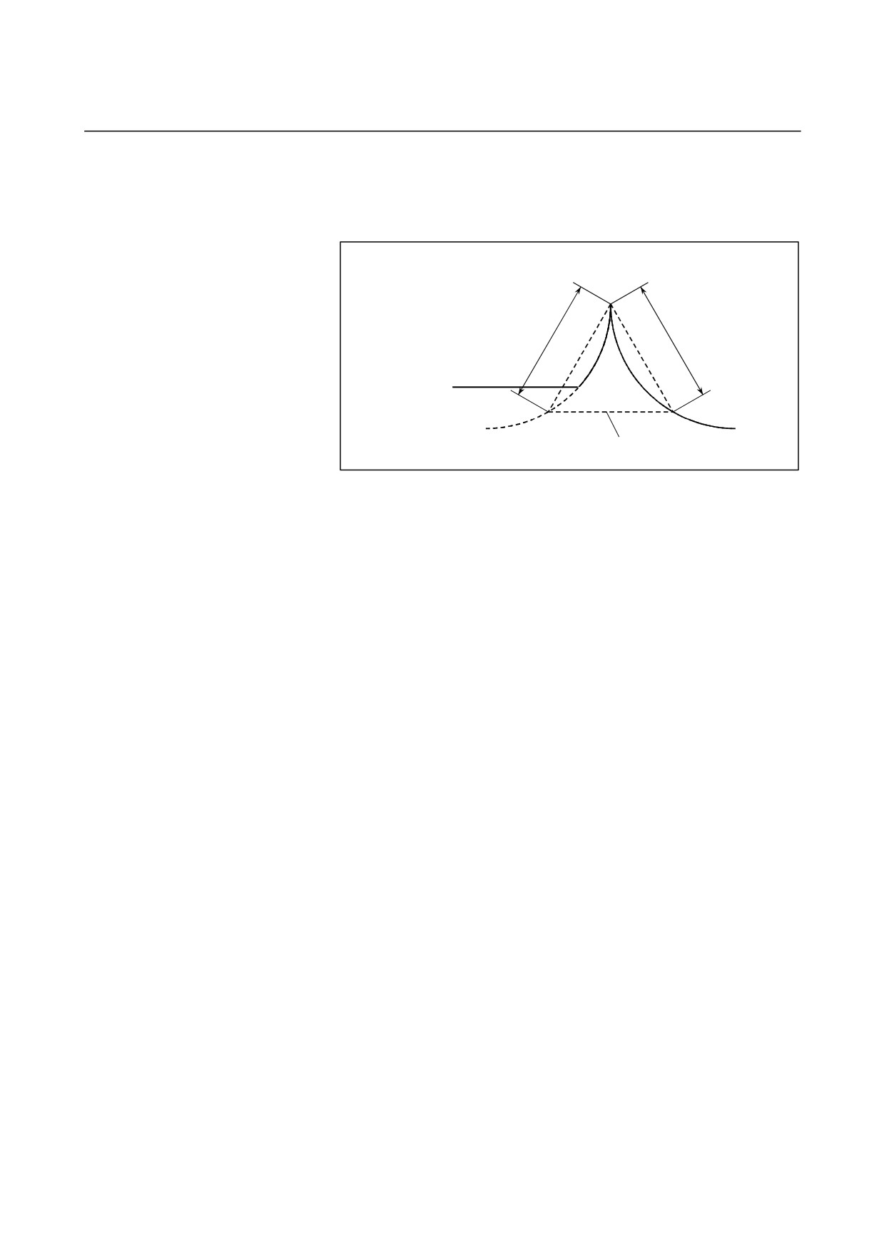
- Exceeding the move range
If the inserted chamfering or corner R block causes the tool to go
beyond the original interpolation move range, alarm PS0055 is issued.
G91 G01 X30.0 ;
G03 X7.5 Y16.0 R37.0 ,C28.0 ;
G03 X67.0 Y-27.0 R55.0 ;
C
C
The tool path without
chamfering is indicated
with a solid line.
Chamfering block to be inserted
Fig 5.3 (a) Exceeding the move range
- Plane selection
A chamfering or corner R block is inserted only for a command to
move the tool within the same plane.
Example:
When the U-axis is set as an axis parallel to the basic X-axis (by
setting parameter No.
1022 to
5), the following program
performs chamfering between cutting feed along the U-axis and
that along the Y-axis:
G17 U0 Y0
G00 U100.0 Y100.0
G01 U200.0 F100 ,C30.0
Y200.0
The following program causes alarm PS0055, however.
(Because chamfering is specified in the block to move the tool
along the X-axis, which is not on the selected plane)
G17 U0 Y0
G00 U100.0 Y100.0
G01 X200.0 F100 ,C30.0
Y200.0
The following program also causes alarm PS0055.
(Because
the block next to the chamfering command moves the tool along
the X-axis, which is not on the selected plane)
G17 U0 Y0
G00 U100.0 Y100.0
G01 Y200.0 F100 ,C30.0
X200.0
If a plane selection command (G17, G18, or G19) is specified in the
block next to the block in which chamfering or corner R is specified,
alarm PS0051 is issued.
- 92 -
5.FUNCTIONS TO SIMPLIFY
B-64304EN-2/01
PROGRAMMING
PROGRAMMING
- Travel distance 0
When two linear interpolation operations are performed, the
chamfering or corner R block is regarded as having a travel distance
of zero if the angle between the two straight lines is within ±1°.
When linear interpolation and circular interpolation operations are
performed, the corner R block is regarded as having a travel distance
of zero if the angle between the straight line and the tangent to the arc
at the intersection is within ±1°. When two circular interpolation
operations are performed, the corner R block is regarded as having a
travel distance of zero if the angle between the tangents to the arcs at
the intersection is within ±1°.
- Single block operation
When the block in which chamfering or corner R is specified is
executed in the single block mode, operation continues to the end
point of the inserted chamfering or corner R block and the machine
stops in the feed hold mode at the end point. When bit 0 (SBC) of
parameter No. 5105 is set to 1, the machine stops in the feed hold
mode also at the start point of the inserted chamfering or corner R
block.
- Unusable G codes
The following G codes are unusable in the same block as for
chamfering or corner R commands or with a block for chamfering or
corner R inputs that define continuous figures.
・G codes (except G04) in group 00
・G68 in group 16
- Threading
If ”,C” or “,R” is specified in a threading command block, the alarm
PS0050 is issued.
NOTE
When ",C" and ",R" are specified in the same
block, the address specified last is valid.
- 93 -
5. FUNCTIONS TO SIMPLIFY
PROGRAMMING
PROGRAMMING
B-64304EN-2/01
5.4
INDEX TABLE INDEXING FUNCTION
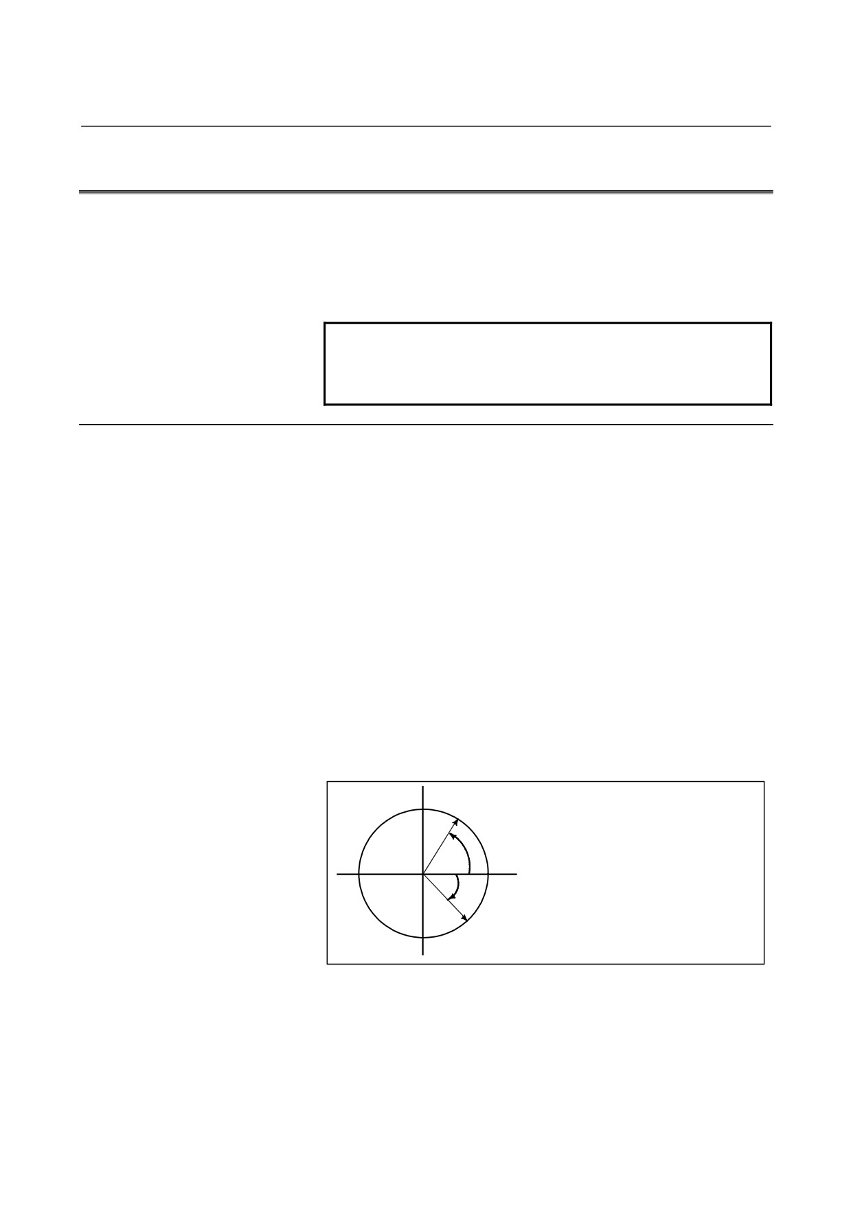
By specifying indexing positions (angles) for the indexing axis (one
rotation axis, A, B, or C), the index table of the machining center can
be indexed.
Before and after indexing, the index table is automatically unclamped
or clamped .
NOTE
To enable the index table indexing function, reset
bit 0 (ITI) of parameter No. 5501 to "0" and set bit 3
(IXC) of parameter No. 8132 to "1".
Explanation
- Indexing position
Specify an indexing position with address A, B, or C (set to bit 0 of
parameter ROTx No.1006).
The indexing position is specified by either of the following
(depending on bit 4 of parameter G90 No.5500):
1.
Absolute value only (Bit 4 (G90) of parameter No.5500 =1)
2.
Absolute or incremental value depending on the specified G
code: G90 or G91 (Bit 4 (G90) of parameter No.5500 =0)
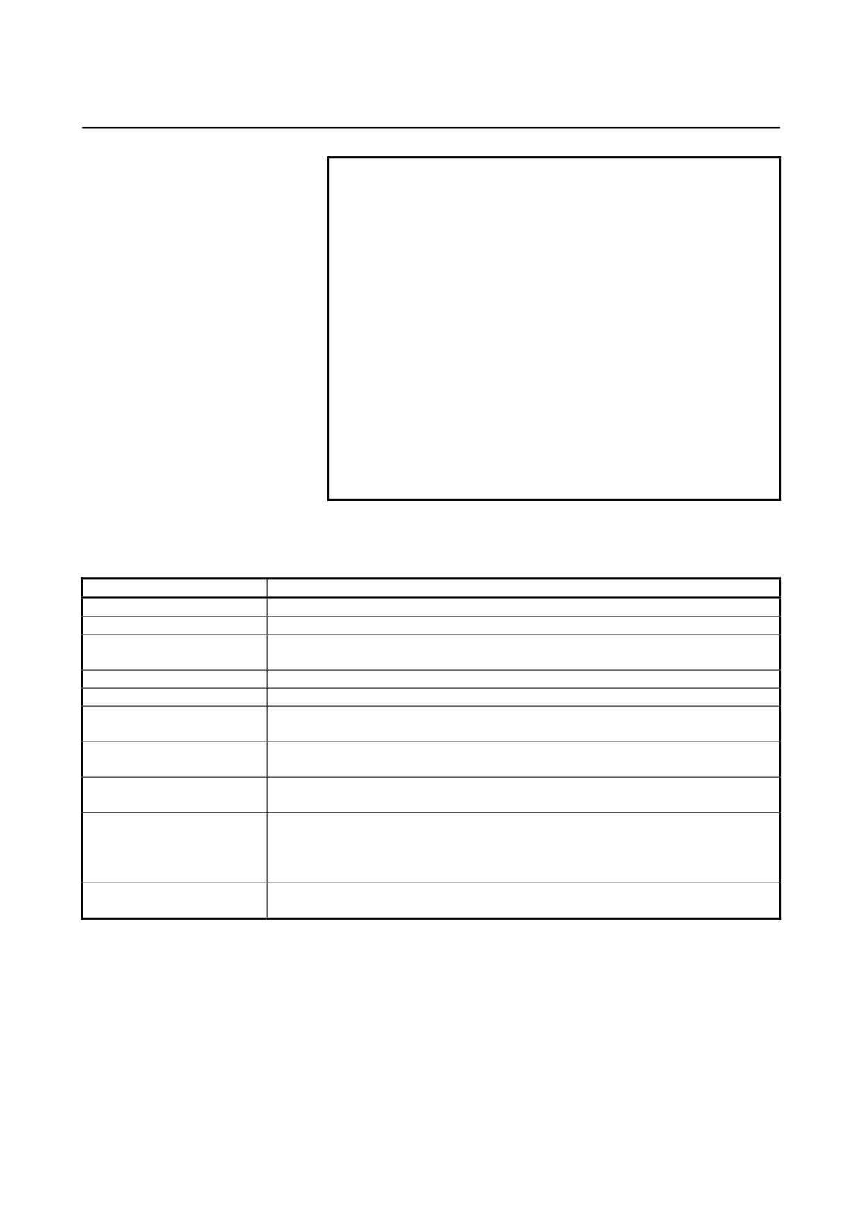
A positive value indicates an indexing position in the
counterclockwise direction. A negative value indicates an indexing
position in the clockwise direction.
The minimum indexing angle of the index table is the value set to
parameter 5512. Only multiples of the least input increment can be
specified as the indexing angle. If any value that is not a multiple is
specified, an alarm PS1561 occurs. Decimal fractions can also be
entered. When a decimal fraction is entered, the 1's digit corresponds
to degree units.
A
Value specified for rotation from A to B
(case 2 described above)
G90 B-45.0 ; or
G91 B-105.0;
+60°
0°
-45°
B
- 94 -
5.FUNCTIONS TO SIMPLIFY
B-64304EN-2/01
PROGRAMMING
PROGRAMMING
- Direction and value of rotation
The direction of rotation and angular displacement are determined by
either of the following two methods. Refer to the manual written by
the machine tool builder to find out which method is applied.
1.
Using the auxiliary function specified in parameter No. 5511
(Address) (Indexing position) (Auxiliary function); Rotation in
the negative direction (Address) (Indexing position); Rotation in
the positive direction (No auxiliary functions are specified.)
An angular displacement greater than 360° is rounded down to
the corresponding angular displacement within 360° when bit 2
of parameter ABS No. 5500 specifies this option.
For example, when G90 B400.0 (auxiliary function); is specified
at a position of 0 , the table is rotated by 40° in the negative
direction.
2.
Using no auxiliary functions
By setting to bits
2,
3, and
4 of parameter ABS, INC,G90
No.5500, operation can be selected from the following two
options.
Select the operation by referring to the manual written by the
machine tool builder.
(1) Rotating in the direction in which an angular displacement
becomes shortest
This is valid only in absolute programming. A specified
angular displacement greater than 360° is rounded down to
the corresponding angular displacement within 360° when
bit 2 of parameter ABS No.5500 specifies this option.
For example, when G90 B400.0; is specified at a position of
0, the table is rotated by 40° in the positive direction.
(2) Rotating in the specified direction
In the absolute programming, the value set in bit
2 of
parameter ABS No.5500 determines whether an angular
displacement greater than
360° is rounded down to the
corresponding angular displacement within 360°.
In the incremental programming, the angular displacement
is not rounded down. For example, when G90 B720.0; is
specified at a position of 0, the table is rotated twice in the
positive direction, when the angular displacement is not
rounded down.
- Feedrate
The table is always rotated around the indexing axis in the rapid
traverse mode.
Dry runs cannot be executed for the indexing axis.
WARNING
If a reset is made during indexing of the index
table, a reference position return must be made
before each time the index table is indexed
subsequently.
- 95 -
5. FUNCTIONS TO SIMPLIFY
PROGRAMMING
PROGRAMMING
B-64304EN-2/01
NOTE
1 If an index table indexing axis and another
controlled axis are specified in the same block
either alarm PS1564 is issued or the command is
executed, depending on bit 6 (SIM) of parameter
No. 5500 and bit 0 (IXS) of parameter No. 5502.
2 The waiting state which waits for completion of
clamping or unclamping of the index table is
indicated on diagnosis display No.12.
3 The auxiliary function specifying a negative
direction is processed in the CNC.
The relevant M code signal and completion signal
are sent between the CNC and the machine.
4 If a reset is made while waiting for completion of
clamping or unclamping, the clamp or unclamp
signal is cleared and the CNC exits the completion
wait state.
- Indexing function and other functions
Table 5.4 (a) Index indexing function and other functions
Item
Explanation
Relative position display
This value is rounded down when bit 1 of parameter REL No.5500 specifies this option.
Absolute position display
This value is rounded down when bit 2 of parameter ABS No.5500 specifies this option.
Movement in the machine
Impossible to move
coordinate system (G53)
Single direction positioning
Impossible to specify
2nd auxiliary function (B code)
Possible with any address other than B that of the indexing axis.
Operations while moving the
Unless otherwise processed by the machine, feed hold, interlock and emergency stop
indexing axis
can be executed. Machine lock can be executed after indexing is completed.
Disabled
SERVO OFF signal
The indexing axis is usually in the servo-off state.
Incremental commands for
The workpiece coordinate system and machine coordinate system must always agree
indexing the index table
with each other on the indexing axis (the workpiece zero point offset value is zero.).
Manual operation is disabled in the JOG, INC, or HANDLE mode.
Operations for indexing the
A manual reference position return can be made. If the axis selection signal is set to
index table
zero during manual reference position return, movement is stopped and the clamp
command is not executed.
This function cannot be used on an axis on which the pole position detection function is
Pole position detection function
used.
- 96 -
5.FUNCTIONS TO SIMPLIFY
B-64304EN-2/01
PROGRAMMING
PROGRAMMING
5.5
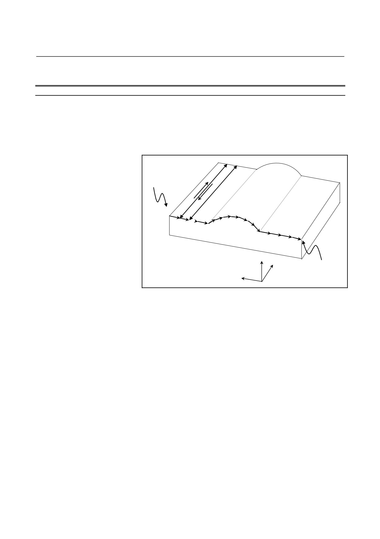
IN-FEED CONTROL (FOR GRINDING MACHINE)
Overview
Each time the switch on the machine operator's panel is input when
the machine is at a table swing end point, the machine makes a cut by
a constant amount along the programmed profile on the specified YZ
plane. This makes it possible to perform grinding and cutting in a
timely manner and facilitating the grinding of a workpiece with a
profile.
X=a
C
•
•
External
(2)
signal input
(3)
A
α
•
(1)
•
•
B(4)
D
Y
X=0
X
Sensor placement
Z
For example, it is possible to machine a workpiece with a profile
programmed with linear interpolation, circular interpolation, and
linear interpolation on the YZ plane, such as that shown in the figure
above.
A sensor is placed at a X = 0 position so that the switch on the
machine operator's panel is input when the sensor detects the grinding
wheel. When the program is started at point A, the machine is first
placed in the state in which it waits for the input of the switch on the
machine operator's panel. Then, when the sensor detects the grinding
wheel, the switch on the machine operator's panel is input, and the
machine makes a cut by the constant amount α along the programmed
profile on the specified YZ plane and moves to point B (operation (1)).
The machine is then placed in the state in which it waits for the input
of the switch on the machine operator's panel again, and performs a
grinding operation along the X-axis. It grinds from point B to point C
(operation (2)) and grinds back from point C to point B (operation (3)).
When the machine returns to point B, the sensor detects the grinding
wheel again, and the switch on the machine operator's panel is input,
so that the machine makes a cut by the amount of α and moves to
point D (operation (4)). At point D, the machine performs a grinding
operation along the X-axis.
Afterwards, each time the switch on the machine operator's panel is
input, the machine makes a cut by the amount of α along the profile
program, so that the workpiece is machined to a profile such as that
shown in the figure above.
- 97 -

5. FUNCTIONS TO SIMPLIFY
PROGRAMMING
PROGRAMMING
B-64304EN-2/01
NOTE
In-feed control function is optional function.
Format
G161 R_ ;
Profile program
G160 ;
Explanation
- G161 R_
This specifies an operation mode and the start of a profile program.
A dept of cut can be specified with R.
- Profile program
Program the profile of a workpiece on the YZ plane, using linear
interpolation
(G01) or circular interpolation
(G02, G03).
Multiple-block commands are possible.
When a profile program is started, the machine is placed in the state in
which it waits for the input of the switch on the machine operator's
panel. When the switch on the machine operator's panel is input in this
state, the machine makes a cut by the amount of cut specified with R.
Later, until the end point of the program, the machine makes a cut
each time the switch on the machine operator's panel is input. If the
final depth of cut is less than R, the remaining travel distance is
assumed the depth of cut.
The feedrate is the one specified in the program with an F code. As in
normal linear interpolation (G01) or circular interpolation (G02, G03),
override can be applied.
- G160
This specifies the cancellation of an operation mode (end of a profile
program).
Limitation
- G161 R_
If no value is specified with R or if the value specified with R is
negative, alarm PS0230 is issued.
- Profile program
In a profile program, do not issue move commands other than those
for linear interpolation (G01) and circular interpolation (G02, G03).
- 98 -
5.FUNCTIONS TO SIMPLIFY
B-64304EN-2/01
PROGRAMMING
PROGRAMMING
CAUTION
If a move command other than those for linear
interpolation (G01) and circular interpolation (G02,
G03) is issued in a profile program, an unexpected
movement may result.
- Grinding operation
In this operation mode, a grinding operation that causes the machine
to move to and from the grinding wheel cannot be specified in an NC
program. Perform such an operation in another way.
- Block overlap
In this operation mode, block overlap is disabled.
- Switch on the machine operator's panel
The switch on the machine operator's panel is disabled when it is input
before a profile program is started. Input the switch on the machine
operator's panel after the start of a profile program. Also, even if the
switch on the machine operator's panel is input during a cut, this is not
accepted in the next cut. It is necessary to input the switch again after
the end of the cut, when the machine is in the state in which it waits
for the input of the switch on the machine operator's panel.
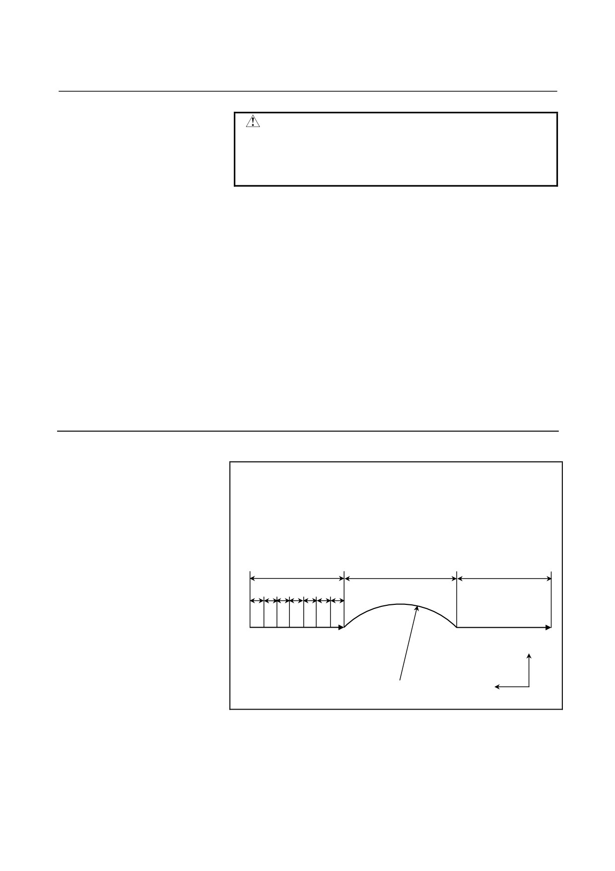
Example
O0001 ;
:
N0 G161 R10.0 ;
N1 G91 G01 Z-70.0 F100 ;
N2 G19 G02 Z-80.0 R67.0 ;
N3 G01 Z-70.0 ;
N4 G160 ;
:
70.0
80.0
70.0
α
N2
N1
N3
Y
R=67.000
Z
The program above causes the machine to move by 10.000 along the
machining profile in the figure above each time the switch on the
machine operator's panel is input.
α = Travel distance at each input of the switch on the machine
operator's panel.
The feedrate is the one specified in the program with an F code.
- 99 -
5. FUNCTIONS TO SIMPLIFY
PROGRAMMING
PROGRAMMING
B-64304EN-2/01
Note
NOTE
If manual intervention is performed during in-feed
control, the tool path after the manual intervention
can be switched by setting the manual absolute
switch to on or off as in normal linear/circular
interpolation. When the manual absolute switch is
on, the machine returns to the programmed path
for an absolute command or for an incremental
command with bit 1 (ABS) of parameter No. 7001
being 1.
- 100 -
5.FUNCTIONS TO SIMPLIFY
B-64304EN-2/01
PROGRAMMING
PROGRAMMING
5.6
CANNED GRINDING CYCLE (FOR GRINDING MACHINE)
With the canned grinding cycle, repetitive machining operations that
are specific to grinding and are usually specified using several blocks
can be specified using one block including a G function. So, a
program can be created simply. At the same time, the size of a
program can be reduced, and the memory can be used more efficiently.
Four types of canned grinding cycles are available:
•
Plunge grinding cycle (G75)
•
Direct constant-dimension plunge grinding cycle (G77)
•
Continuous-feed surface grinding cycle (G78)
•
Intermittent-feed surface grinding cycle (G79)
In the descriptions below, an axis used for cutting with a grinding
wheel and an axis used for grinding with a grinding wheel are referred
to as follows:
Axis used for cutting with a grinding wheel: Cutting axis
Axis used for grinding with a grinding wheel: Grinding axis
Axis on which to make a dresser cut:
Dressing axis
During execution of a canned grinding cycle, the following functions
cannot be used:
•
Programmable mirror image
•
Scaling
•
Coordinate system rotation
•
One-digit F code feed
•
Tool length compensation
For a depth of cut on a cutting axis and a distance of grinding on a
grinding axis, the incremental system (parameter No. 1013) for the
reference axis (parameter No. 1031) is used. If 0 is set in parameter
No. 1031 (reference axis), the incremental system for the first axis is
used.
- 101 -
5. FUNCTIONS TO SIMPLIFY
PROGRAMMING
PROGRAMMING
B-64304EN-2/01
WARNING
The G codes for canned grinding cycles G75, G77,
G78, and G79 are G codes of group 01. A G code
for cancellation such as G80 used for a canned
cycle for drilling is unavailable. By specifying a G
code of group 00 other than G04, modal information
such as a depth of cut is cleared but no canned
grinding cycle can be canceled. To cancel a canned
grinding cycle, a G code of group 01 other than
G75, G77, G78, and G79 needs to be specified. So,
when switching to another axis move command
from canned grinding cycles, for example, be sure
to specify a G code of group 01 such as G00 or G01
to cancel the canned grinding cycle. If another axis
move command is specified without canceling the
canned grinding cycle, an unpredictable operation
can result because of continued cycle operation.
NOTE
1 If the G code for a canned grinding cycle (G75,
G77, G78, or G79) is specified, the canned grinding
cycle is executed according to the values of I, J, K,
α, R, F, and P preserved as modal data while the
cycle is valid, even if a block specified later
specifies none of G75, G77, G78, and G79.
Example:
G75 I_ J_ K_ α_ R_ F_ P_ ;
;
← The canned grinding cycle is executed even
if an empty block is specified.
%
2 When switching from a canned cycle for drilling to a
canned grinding cycle, specify G80 to cancel the
canned cycle for drilling.
3 When switching from a canned grinding cycle to
another axis move command, cancel the canned
cycle according to the warning above.
- 102 -
5.FUNCTIONS TO SIMPLIFY
B-64304EN-2/01
PROGRAMMING
PROGRAMMING
5.6.1
Plunge Grinding Cycle (G75)
A plunge grinding cycle can be executed.
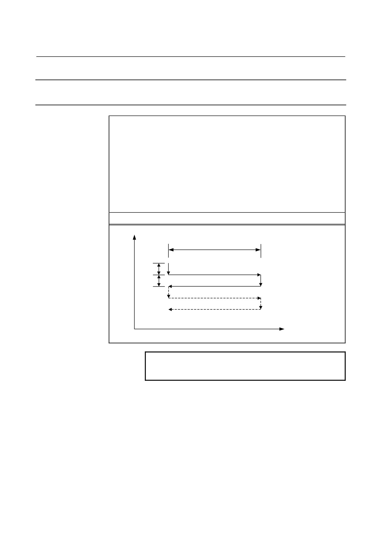
Format
G75 I_ J_ K_ α_ R_ F_ P_ L_ ;
I_
: First depth of cut (The cutting direction depends on the sign.)
J_
: Second depth of cut (The cutting direction depends on the sign.)
K_ : Total depth of cut (The cutting direction depends on the sign.)
α_
: Grinding range (The grinding direction depends on the sign.)
R_ : Feedrate for I and J
F_
: Feedrate for α
P_ : Dwell time
L_
: Grinding-wheel wear compensation number (during continuous
dressing only)
G75
Y
α
I
<1> (R)
<3> (F)
<2> P
<4> (R)
J
<6> (F)
<5> P
α
NOTE
α is an arbitrary axis address on the grinding axis
as determined with parameter No. 5176.
- 103 -
5. FUNCTIONS TO SIMPLIFY
PROGRAMMING
PROGRAMMING
B-64304EN-2/01
Explanation
A plunge grinding cycle consists of a sequence of six operations.
Operations <1> to <6> are repeated until the depth of cut reaches the
total depth of cut specified with address K. For a single block,
operations <1> to <6> are executed with a single cycle start.
- Operation sequence in a cycle
<1> Cutting with a grinding wheel
Makes a cut in the Y-axis direction with cutting feed by the amount
specified as the first depth of cut I. The feedrate is the one specified
with R.
<2> Dwell
Performs a dwell for the time specified with P.
<3> Grinding
Causes the machine to move with cutting feed by the amount specified
with α. The grinding axis is specified with parameter No. 5176. The
feedrate is the one specified with F. If L is specified when the
continuous dressing function is enabled, dressing is performed with
the cutting axis and the dressing axis. The dressing axis is specified
with parameter No. 5180.
<4> Cutting with a grinding wheel
Makes a cut in the Y-axis direction with cutting feed by the amount
specified as the second depth of cut J. The feedrate is the one specified
with R.
<5> Dwell
Performs a dwell for the time specified with P.
<6> Grinding (return direction)
Feeds the machine at the feedrate specified with F in the opposite
direction by the amount specified with α. If L is specified when the
continuous dressing function is enabled, dressing is performed with
the cutting axis and the dressing axis.
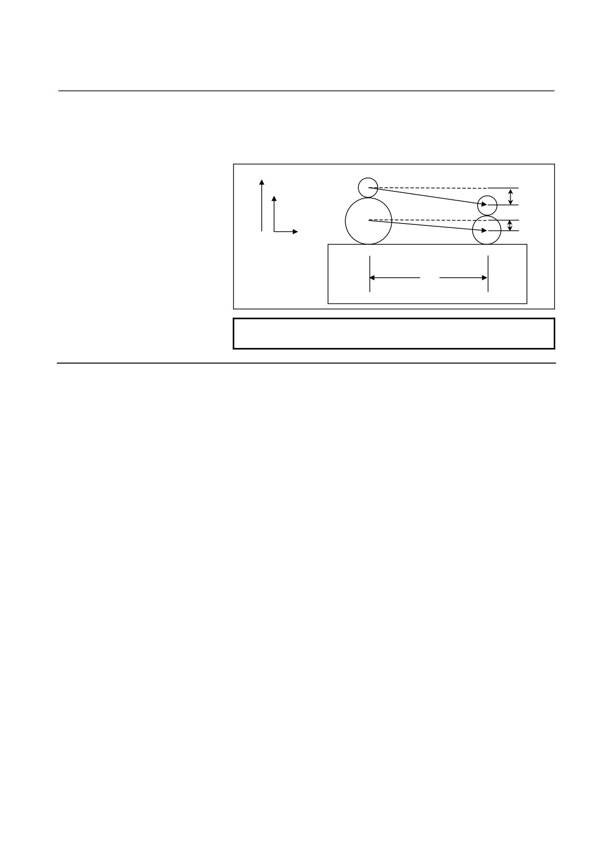
- Continuous dressing
If the continuous dressing function is enabled, the grinding-wheel cut
and the dresser cut are continuously compensated for according to the
dressing amount specified with L during the execution of grinding.
That is, continuous dressing is performed in each grinding operation
in the sequence of operations in the cycle, resulting in simultaneous
3-axis interpolation with compensation in the cutting axis direction
and compensation in the dressing axis direction simultaneous with
movement along the grinding axis. At this time, the travel distance
(compensation) along the cutting axis is equal to the specified dressing
amount, and the travel distance along the dressing axis is equal to
double the specified dressing amount (diameter).
For the dressing amount, specify an offset number (grinding-wheel
wear compensation number) with address L. Up to 400 offset numbers
(L1 to L400) can be specified. Establish correspondence between
compensation amounts and offset numbers, and set it in offset memory
in advance, using the MDI panel.
- 104 -
5.FUNCTIONS TO SIMPLIFY
B-64304EN-2/01
PROGRAMMING
PROGRAMMING
No compensation operation is performed in the following cases:
The continuous dressing function is disabled.
L is not specified.
L0 is specified.
Dresser
a: Amount of dressing
Dressing axis
Cutting axis
2a
Grinding wheel
a
Grinding axis
Workpiece
α
NOTE
Continuous dressing function is optional function.
Limitations
- Cutting axis
The cutting axis is the second controlled axis. By setting bit 0 (FXY)
of parameter No. 5101 to 1, the axis can be switched with a plane
selection command (G17, G18, or G19).
- Grinding axis
To specify a grinding axis, set its axis number, which must be other
than that of the cutting axis, in parameter No. 5176.
- Dressing axis
To specify a dressing axis, set its axis number, which must be other
than those of the cutting axis and the grinding axis, in parameter No.
5180.
- α,I,J,K
α, I, J, and K commands are all incremental ones.
Spark-out (execution of movement in the grinding direction only)
occurs in the following cases:
•
I or J is not specified or I = J = 0
•
K is not specified or K = 0
If I or J is not specified or if I = J = 0 is true, and K is not equal to 0, a
grinding operation is performed infinitely.
- Clearing
The data items I, J, K, α, R, F, and P in a canned cycle are modal
information common to G75, G77, G78, and G79, so that once
specified, they remain effective until specified anew. The data is
cleared when a G code of group 00 other than G04 or a G code of
group 01 other than G75, G77, G78, and G79 is specified. L is
effective only in the block in which it is specified.
- 105 -