FANUC Series 0i-MODEL C, Series 0i Mate-MODEL C. PARAMETER MANUAL (B-64120EN/01) - page 13
4.DESCRIPTION OF PARAMETERS
B-64120EN/01
4.46
PARAMETERS OF FS0i BASIC FUNCTIONS
8130
Total number of controlled axes
NOTE
When this parameter has been set, the power must
be turned off before operation is continued.
[Data type]
Byte
[Valid data range]
2 to 4
This parameter sets the total number of axes controlled by the CNC.
#7
#6
#5
#4
#3
#2
#1
#0
EDC
HPG
8131
AOV
EDC
F1D
HPG
NOTE
When this parameter has been set, the power must
be turned off before operation is continued.
[Data type]
Bit
HPG
Manual handle feed is:
0 : Not Used.
1 : Used.
F1D
One-digit F code feed is:
0 : Not Used.
1 : Used.
EDC
External deceleration is:
0 : Not Used.
1 : Used.
AOV
Automatic corner override is:
0 : Not Used.
1 : Used.
#7
#6
#5
#4
#3
#2
#1
#0
BCD
YOF
TLF
8132
SCL
SPK
IXC
BCD
TLF
NOTE
When this parameter has been set, the power must
be turned off before operation is continued.
[Data type]
Bit
TFL
Tool life management is:
0 : Not Used.
1 : Used.
- 352 -
B-64120EN/01
4.DESCRIPTION OF PARAMETERS
NOTE
When TLF is changed, the data listed below is
erased.
Therefore, before changing TLF, save the following
data:
- Additional custom macro common variable data
- Tool offset data
- Tool life management data
- Additional workpiece coordinate system data
(0i-MC / 0i Mate-MC only)
YOF
Y-axis offset is:
0 : Not Used.
1 : Used.
BCD
Second auxiliary function is:
0 : Not Used.
1 : Used.
IXC
Index table indexing is:
0 : Not Used.
1 : Used.
SPK
Small diameter peck drinlling cycle is:
0 : Not Used.
1 : Used.
SCL
Scaling is:
0 : Not Used.
1 : Used.
#7
#6
#5
#4
#3
#2
#1
#0
SSN
SYC
MSP
SCS
AXC
SSC
8133
SSN
SYC
SCS
SSC
NOTE
1 When this parameter has been set, the power must
be turned off before operation is continued.
2 A small diameter peck drilling cycle and scaling
cannot be used at the same time.
[Data type]
Bit
SSC
Constant surface speed control is:
0 : Not Used.
1 : Used.
AXC
Spindle positioning is:
0 : Not Used.
1 : Used.
SCS
Cs cotour control is:
0 : Not Used.
1 : Used.
MSP
Multi-spindle is:
0 : Not Used.
1 : Used.
- 353 -
4.DESCRIPTION OF PARAMETERS
B-64120EN/01
SYC
Spindle synchronization is:
0 : Not Used.
1 : Used.
SSN
Serial spindle function is:
0: Used. (The analog spindle function is not used.)
1: Not Used. (The analog spindle function is used.)
NOTE
Spindle positioning and Cs contour control by the
serial spindle cannot be used at the same time.
#7
#6
#5
#4
#3
#2
#1
#0
CCR
BAR
IAP
8134
IAP
NOTE
When this parameter has been set, the power must
be turned off before operation is continued.
[Data type]
Bit
IAP
Conversational programming with graphic function is:
0 : Not Used.
1 : Used.
BAR
Chuck and tail stock barrier function is:
0 : Not Used.
1 : Used.
CCR
Chamfering / corner R is:
0 : Not Used.
1 : Used.
NOTE
When the chuck and tail stock barrier function is
selected, stored stroke limits 2 and 3 cannot be
used.
- 354 -
B-64120EN/01
4.DESCRIPTION OF PARAMETERS
4.47
PARAMETERS OF ANGULAR AXIS CONTROL
#7
#6
#5
#4
#3
#2
#1
#0
8200
AZP
AZR
AAC
NOTE
When this parameter is set, the power must be
turned off before operation is continued.
[Data type]
Bit
AAC
0 : Does not perform angular axis control.
1 : Performs inclined axis control.
AZR
0 : The machine tool is moved along the Cartesian axis during
manual reference position return along the slanted axis under
angular axis control.
1 : The machine tool is not moved along the Cartesian axis during
manual reference position return along the slanted axis under
angular axis control.
AZP
When an angular axis moves, the reference position return completion
signal for the Cartesian axis, ZPx <F094, F096, F098, or F100>, is:
0 : Not cleared.
1 : Cleared.
#7
#6
#5
#4
#3
#2
#1
#0
ADG
A53
ACL
ALN
AO3
AO2
AOT
8201
ADG
A53
ACL
ALN
AO2
AOT
[Data type]
Bit
AOT
When angular axis control is enabled, the values indicating the area
for stored stroke check 1 (parameters Nos. 1320, 1321, 1326, and
1327) are treated as:
0 : Coordinates in the angular coordinate system.
1 : Coordinates in the Cartesian coordinate system.
AO2
When angular axis control is enabled, the values indicating the area
for stored stroke check 2 (parameters Nos. 1322 and 1323) are treated
as:
0 : Coordinates in the angular coordinate system.
1 : Coordinates in the Cartesian coordinate system.
AO3
When angular axis control is enabled, the values indicating the area
for stored stroke check 3 (parameters Nos. 1324 and 1325) are treated
as:
0 : Coordinates in the angular coordinate system.
1 : Coordinates in the Cartesian coordinate system.
- 355 -
4.DESCRIPTION OF PARAMETERS
B-64120EN/01
ALN
When manual rapid traverse or reference position return without dogs
is performed for an angular axis during angular axis control:
0 : The acceleration/deceleration time for a Cartesian axis is not
controlled.
1 : The acceleration/deceleration time for a Cartesian axis is
controlled so that it matches the acceleration/deceleration time
for the angular axis. (A linear path is formed by the angular axis
and Cartesian axis.)
ACL
In linear interpolation type rapid traverse, the feedrate clamp function
for angular axis control is:
0 : Enabled.
1 : Disabled.
NOTE
This parameter is valid when bit 1 (LRP) of
parameter No. 1401 is set to 1.
A53
During angular axis control, when a machine coordinate system
command (G53) specifies an angular axis alone:
0 : A movement along a Cartesian axis is also made.
1 : A movement is made along the angular axis only.
ADG
The contents of diagnostic data Nos. 306 and 307 are:
0 : Not swapped. The angular axis and Cartesian axis are displayed
in this order.
1 : Swapped. The Cartesian axis and angular axis are displayed in
this order.
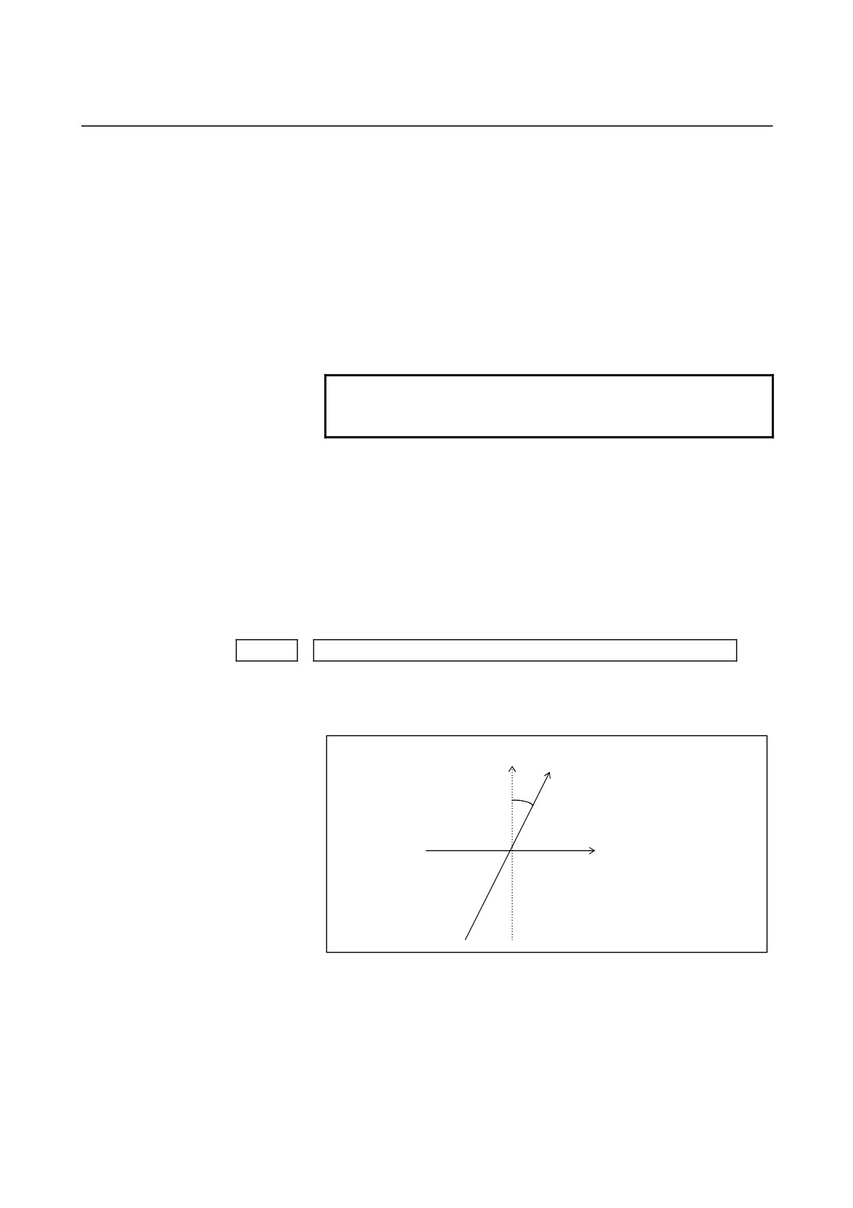
8210
Inclination angle for angular axis control
[Data type]
2-word
[Unit of data]
0.001 degree
[Valid data range]
20000 to 60000
+X Program coordinate system
+X (angular axis):
Actual movement coordinate system
θ
+Z (Cartesian axis)
θ : Inclination angle
- 356 -

B-64120EN/01
4.DESCRIPTION OF PARAMETERS
Axis number of a slanted axis subject to angular axis control
8211
Axis number of a Cartesian axis subject to slanted axis control
8212
[Data type] Byte
[Unit of data] Axis number
[Valid data range]
1 to number of controlled axes
When angular axis control is to be applied to an arbitrary axis, these
parameters set the axis numbers of a slanted axis and Cartesian axis.
- 357 -
4.DESCRIPTION OF PARAMETERS
B-64120EN/01
4.48
PARAMETERS OF SIMPLE SYNCHRONOUS CONTROL
#7
#6
#5
#4
#3
#2
#1
#0
8301
SOF
SYE
SYA
[Data type]
Bit
SYA
In the servo-off state in simple synchronous control, the limit of the
difference between the positioning deviation of the master axis and
that of the slave axis is:
0 : Checked.
1 : Not checked.
SYE
During execution of synchronization, the limit of the difference
between positioning deviations (parameter No. 8313 or 8323) is:
0 : Checked.
1 : Not checked.
SOF
The synchronization function in simple synchronous control (one pair)
is:
0 : Not used.
1 : Used.
#7
#6
#5
#4
#3
#2
#1
#0
8302
SMA
SSE
ATS
ATE
NOTE
When this parameter is set, the power must be
turned off before operation is continued.
[Data type]
Bit
ATE
Automatic setting of grid positioning for simplified synchronous
control one pair is:
0 : Disabled
1 : Enabled
ATS
Automatic setting of grid positioning for simplified synchronous
control one pair is:
0 : Not started
1 : Started
NOTE
1 When the bits are set to 1, parameter No.8316 and
bit 4 (APZx) of parameter No.1815 for the master
and slave axes are set to 0.
2 These bits are automatically set to 0 once grid
positioning has been completed.
SSE
In simple synchronization control, the external machine coordinate
system shift function for the slave axis is:
0 : Not used.
- 358 -
B-64120EN/01
4.DESCRIPTION OF PARAMETERS
1 : Used.
For axes under simple synchronization control, when the external
machine coordinate system shift is performed for the master axis, it
can also performed for the slave axis simultaneously.
NOTE
The simple synchronous signal must be
manipulated.
Carefully turn the simple synchronous signal on
and off because the machine may move at that
time.
SMA
When bit 4x (APZx) of parameter No. 1815 is turned off for one axis
under simple synchronous control, APZx for the other axis under
simple synchronous control is:
0 : Not turned off.
1 : Turned off.
When an axis for which the simple synchronous axis parameter is set
is under simple synchronous control, the simple synchronous signal is
turned on for the axis.
#7
#6
#5
#4
#3
#2
#1
#0
8303
SOFx
ATSx
ATEx
NOTE
After this parameter has been set, the power must
be turned off then on again for the setting to
become effective.
[Data type]
Bit axis
ATEx
In simple synchronous control, automatic setting for grid positioning
is:
0 : Disabled.
1 : Enabled.
ATSx
In simple synchronous control, automatic setting for grid positioning
is:
0 : Not started.
1 : Started.
NOTE
When starting automatic setting for grid positioning,
set ATSx to 1. Upon the completion of setting,
ATSx is automatically set to 0.
SOFx
In simple synchronous control, the synchronization function is:
0 : Not used.
1 : Used.
- 359 -
4.DESCRIPTION OF PARAMETERS
B-64120EN/01
NOTE
Set this parameter on the master axis side.
#7
#6
#5
#4
#3
#2
#1
#0
8304
USD
[Data type]
Bit axis
USD
In simple synchronous control, the uni-directional synchronization
function uses:
0 : Axis of which machine coordinate is larger as the reference.
1 : Axis of which machine coordinate is smaller as the reference.
NOTE
Set this parameter (USD) to the same value for
both the master and slave axes.
#7
#6
#5
#4
#3
#2
#1
#0
8305
USE
USC
[Data type]
Bit
USC
In simple synchronous control, the uni-directional synchronization
function is:
0 : Not used.
1 : Used.
NOTE
This parameter is valid only when bit 7 (SOF) of
parameter No. 8301 or bit 7 (SOFx) of parameter
No. 8303 is set to 1.
USE
In simple synchronous control, after emergency stop, the
uni-directional synchronization function is:
0 : Used.
1 : Not used.
NOTE
This parameter is valid only when bit 7 (SOF) of
parameter No. 8301 or bit 7 (SOFx) of parameter
No. 8303 is set to 1.
- 360 -
B-64120EN/01
4.DESCRIPTION OF PARAMETERS
8311
Axis number of master axis in synchronous control
NOTE
When this parameter is set, the power must be
turned off before operation is continued.
[Data type]
Byte axis
<For the T series>
[Valid data range]
0 to (Number of controlled axes - 1)
Select a master axis and slave axis in simple synchronous control. Set
a master axis number with a slave axis. For the parameters for the first
axis through the fourth axis of parameter No.8311, set the following:
Units digit of the parameter for the first axis →
Set the axis number of the master axis when the first axis is used
as the slave axis.
Tens digit of the parameter for the first axis →
Set the axis number of the master axis when the second axis is
used as the slave axis.
Units digit of the parameter for the second axis →
Set the axis number of the master axis when the third axis is used
as the slave axis.
Tens digit of the parameter for the second axis →
Set the axis number of the master axis when the fourth axis is
used as the slave axis.
Units digit of the parameter for the third axis →
Always set to 0.
Tens digit of the parameter for the third axis →
Always set to 0.
Units digit of the parameter for the fourth axis →
Always set to 0.
Tens digit of the parameter for the fourth axis →
Always set to 0.
Number
Tens digit
Units digit
No.8311 : First axis
Second axis
First axis
No.8311 : Second axis
Fourth axis
Third axis
Note that the axis number settings are as follows:
0 -> First axis, 1 -> Second axis, 2 -> Third axis, 3 -> Fourth axis
Example:
To use the third axis as the master axis and the fourth axis as the
slave axis, set the axis number (setting of 2) of the third axis
(master axis) in the tens digit for the second axis in the fourth
axis (slave axis) parameter, that is, parameter No. 8311.
No. 8311
First:
00
Second:
20
Third:
00
Fourth:
00
- 361 -

4.DESCRIPTION OF PARAMETERS
B-64120EN/01
NOTE
For an axis for which 0 is set, the first axis serves
as the master axis. So, when the control signal for
the axis is set to 1, the first axis serves as a master
axis, and synchronous control is exercised.
<For the M series>
[Valid data range]
0, 1 to Number of controlled axes
Select a master axis and slave axis in simple synchronous control. Set
a master axis number with the slave axis side. The axis number
settings are: 1 → First axis, 2 → Second axis, 3 → Third axis, 4 →
Fourth axis. Up to four pairs can be specified.
Example1:
Simple synchronous control is exercised with one pair.
When using the first axis (X-axis) as the master axis, and the
third axis (Z-axis) as the slave axis, set parameter No.8311 as
follows:
Parameter No. 8311 X (first axis)
= 0
Y (second axis)
= 0
Z (third axis)
= 1
A (fourth axis)
= 0
Example2:
Simple synchronous control is exercised with two pairs.
Assume that the following two pairs are to be used:
The master axis is the first axis, while a slave axis is the fourth
axis.
The master axis is the second axis, while a slave axis is the third
axis.
For this specification, set this parameter as follows:
Parameter No.8311
X (First axis)
= 0
Y (Second axis)
= 0
Z (Third axis)
= 2
(Fourth axis)
= 1
NOTE
The axis number of a master axis must always be
smaller than the corresponding slave axis number.
Multiple slave axes cannot be assigned to a master
axis.
Enabling/disabling mirror image in synchronous control
8312
[Data type]
Byte axis
[Valid data range]
-127 to +128
This parameter sets the mirror image function. When 100 or a greater
value is set with this parameter, the mirror image function is applied to
synchronous control. Set this parameter to the slave axis.
- 362 -
B-64120EN/01
4.DESCRIPTION OF PARAMETERS
[Example]
To establish reversed synchronization when using the third axis
as the master axis and the fourth axis as the slave axis, set
parameter
No.8311 and parameter No.8312 as follows:
Parameter No.8311 (first axis)
= 0
Parameter No.8311 (second axis) = 20
Parameter No.8311 (third axis)
= 0
Parameter No.8311 (fourth axis) = 0
Parameter No.8312 (first axis) = 0
Parameter No.8312 (second axis) = 0
Parameter No.8312 (third axis) = 0
Parameter No.8312 (fourth axis) = 100
8313
Limit of the difference between the amount of positioning deviation of the
master and slave axes (Synchronous control one pair)
[Data type]
Word
[Unit of data]
Detection unit
[Valid data range]
0 to 32767
Set the limit of the difference between the amount of positioning
deviation of the master and slave axes. If the difference between them
exceeds the limit assigned to the parameter, the P/S alarm (No.213) is
activated.
8314
Maximum error in synchronization error check
[Data type]
Word axis
[Unit of data]
Input increment
IS-A
IS-B
IS-C
Unit
Millimeter machine
0.01
0.001
0.0001
mm
Inch machine
0.001
0.0001
0.00001
inch
Rotation axis
0.01
0.001
0.0001
deg
[Valid data range]
0 to 32767
The machine coordinates on a master axis and slave axis are
monitored. If a difference (synchronization error) which is greater
than the value specified in this parameter is detected, a servo alarm
(No.407) is generated, and the machine is stopped.
Set this parameter with a master axis. When 0 is set in this parameter,
no synchronization error check is made.
- 363 -

4.DESCRIPTION OF PARAMETERS
B-64120EN/01
8315
Maximum compensation value for synchronization (Synchronous control
one pair)
[Data type] Word axis
[Unit of data] Unit used for the detection
[Valid data range]
0 to 32767
This parameter sets the maximum compensation value for
synchronization. When a compensation value greater than the value
set in this parameter is used, servo alarm No.410 of slave axis is
issued.
8316
Difference between reference counters for master and slave axes
(Synchronous control one pair)
NOTE
When this parameter is set, the power must be
turned off before operation is continued.
[Data type]
2-word
[Data unit]
Detection unit
[Valid data range]
-99999999 to 99999999
This parameter indicates the difference between the values in the
reference counter for the master axis and that for the slave axis.
NOTE
Once grid positioning has been completed, the
difference between the reference counters is
automatically set in this parameter. At this time, bit
1 (ATS) of parameter No.8302 is set to 0.
8317
Torque difference alarm detection time (Synchronous control one pair)
[Data type]
Word
[Data unit]
ms
[Valid data range]
0 to 4000 (When 0 is set, 512 ms is assumed.)
This parameter specifies the period between the servo preparation
completion signal (SA <F000 bit 6>) being set to 1 and the check of
the torque difference alarm being started, for the torque difference
alarm detection function.
The set value is rounded up to the nearest a multiple of 16 ms.
[Example]
When 100 is specified, 112 ms is assumed.
- 364 -

B-64120EN/01
4.DESCRIPTION OF PARAMETERS
8318
Detection timer for the limit of the difference between the positioning
deviation of the master axis and that of the slave axis
[Data type] Word
[Unit of data]
8m
[Valid data range]
0 to 1000
This parameter sets the time from the output of a compensation pulse
to the slave axis to the start of the check of the limit of the difference
between the positioning deviation of the master axis and that of the
slave axis by the synchronization function. The setting is also used for
the check of an excessive error at stop.
NOTE
If a value greater than 1000 is set, a value of 1000
is assumed.
8323
Maximum allowable difference between master axis and slave axis positional
deviations
[Data type] Word axis
[Unit of data] Detection unit
[Valid data range]
0 to 32767
This parameter sets the maximum allowable difference between the
master axis and slave axis position deviations. If a positional deviation
difference exceeds the value specified in this parameter, an alarm
(No.213) is issued.
Set this parameter with a master axis. If 0 is specified in this parameter,
no position deviation difference check is made.
8325
Maximum compensation value for synchronization
[Data type] Word axis
[Unit of data] Detection unit
[Valid data range]
0 to 32767
This parameter sets the maximum compensation value for
synchronization. If a compensation value exceeds the value specified
with this parameter, a servo alarm (No.407) is issued.
Specify a master axis for this parameter. To enable this parameter, set
the SOFx parameter (bit 7 of parameter No.8303) to 1.
- 365 -

4.DESCRIPTION OF PARAMETERS
B-64120EN/01
8326
Difference between master axis and slave axis reference counters
[Data type]
2-word axis
[Unit of data]
Detection unit
[Valid data range]
-99999999 to 99999999
The difference between the master axis reference counter and slave
axis reference counter
(master axis and slave axis grid shift) is
automatically set when automatic setting for grid positioning is
performed. Then, the difference is transferred together with an
ordinary grid shift value to the servo system when the power is turned
on.
This parameter is set with a master axis.
8327
Torque difference alarm detection timer
[Data type]
Word axis
[Unit of data]
ms
[Valid data range]
0 to 4000
This parameter sets a time from the servo preparation completion
signal, SA (F000#6), being set to 1 until torque difference alarm
detection is started in simple synchronous control. A fraction of less
than 16 msec is rounded up.
Example:
Setting = 100: The specification of 112 msec is assumed.
Set this parameter with a master axis. If 0 is set in this parameter,
the specification of 512 msec is assumed.
- 366 -
B-64120EN/01
4.DESCRIPTION OF PARAMETERS
4.49
PARAMETERS OF SEQUENCE NUMBER COMPARISON
AND STOP
8341
Program number subject to comparison and stop
[Data type]
Word
[Valid data range]
0 to 9999
This parameter sets the program number, including a sequence number,
subject to sequence number comparison and stop. Parameter No.8342
is used to set a sequence number subject to check termination.
NOTE
A program number can also be set on the setting
screen. If a program number is set on the setting
screen, the value of the parameter is changed
accordingly.
8342
Sequence number subject to comparison and stop
[Data type]
2-word
[Valid data range]
0 to 9999
This parameter sets the sequence number subject to sequence number
comparison and stop.
If the block containing the sequence number set with this parameter is
executed while the program set with parameter No.8341 is being
executed, a single block stop occurs after the block is executed. At this
time, the setting is automatically set to -1. Upon power-up, the setting
is automatically set to 0.
NOTE
A sequence number can also be set by using the
setting screen. If a sequence number is set on the
setting screen, the value of the parameter is
changed accordingly.
- 367 -
4.DESCRIPTION OF PARAMETERS
B-64120EN/01
4.50
OTHER PARAMETERS
#7
#6
#5
#4
#3
#2
#1
#0
8700
DMM
[Data type]
Bit
DMM
In DNC operation from the PMC, OPEN CNC, or C-EXE, pre-reading
is:
0 : Not performed.
1 : Performed.
#7
#6
#5
#4
#3
#2
#1
#0
8701
WPR
[Data type]
Bit
WPR
The function that allows parameters that are rewritten using the PMC
window to be enabled during automatic operation is:
0 : Disabled.
1 : Enabled.
NOTE
If this parameter is set, a move command based on
manual operation is disabled (interlock state) while
parameter rewriting using the PMC window is being
executed.
#7
#6
#5
#4
#3
#2
#1
#0
8702
LFM
SME
[Data type]
Bit
SME
During DNC operation or M198 call, parameter No. 8790 (timing for
executing an auxiliary macro) is:
0 : Invalid.
1 : Valid.
LFM
At the beginning of program uploading in response to a request using
the data window library:
0 : "LF+%" is not output.
1 : "LF+%" is output.
#7
#6
#5
#4
#3
#2
#1
#0
8703
WSP
[Data type]
Bit
WSP
When serial spindle parameter Nos. 4000 to 4799 are rewritten with
function code 18 (parameter write) of the PMC window function, the
new data is:
0 : Not transferred to the spindle amplifier immediately.
1 : Transferred to the spindle amplifier immediately.
- 368 -
B-64120EN/01
4.DESCRIPTION OF PARAMETERS
MOTE
1 When a parameter write operation with all axes
specified (axis specification:
-1) is performed with
function code 18 of the PMC window function, this
function cannot be used. (Even if the function is
specified, data for all axes is not transferred to the
spindle amplifier.)
2 When a spindle startup operation is being
performed at the time of power-up and so on, or
when serial spindle parameter data (parameter
Nos. 4000 to 4799) is being rewritten through MDI
keys, RS-232C, or programmable data input (G10),
the serial spindle parameter data (parameter Nos.
4000 to 4799) must not be rewritten with the PMC
window function at the same time.
3
When spindle orientation with the stop position set
externally or incremental command type spindle
orientation (both set by bit 2 (OR1) and bit 3 (OR2)
of parameter No. 3702) is used, the same condition
as described in NOTE 2 above applies if the status
of the spindle orientation external stop position
command signals (below) changes. When a
change to the spindle orientation external stop
position command signals and rewriting of spindle
parameters (parameter Nos. 4000 to 4799) by the
PMC window function are performed successively,
insert a wait time of at least 50 ms between these
operations.
Spindle orientation external stop position command
signals
First spindle SHA00 to SHA11 <G078, G079>
Second spindle SHB00 to SHB11 <G080,
G081>
4
When a parameter has been changed using this
function, it requires 1000 ms for the new parameter
data to become valid on the spindle amplifier side.
To use a parameter as soon as changing it, wait for
at least 1000 ms after the PMC window completion
code is returned.
- 369 -

4.DESCRIPTION OF PARAMETERS
B-64120EN/01
#7
#6
#5
#4
#3
#2
#1
#0
8706
NWD
HSD
NOTE
When this parameter has been set, the power must
be turned off before operation is continued.
[Data type]
Bit
HSD
Main machining during DNC operation with FOCAS1/HSSB is:
0 : Normal operation.
1 : High-speed operation.
Set this parameter according to machining during DNC operation.
Usually, when binary operation and programs containing contiguous
small blocks are performed during DNC operation with
FOCAS1/HSSB, high-speed operation is selected.
NOTE
For details of this parameter, also refer to "FANUC
Open CNC DNC Operation Management Package"
and other manuals.
NWD
During DNC operation with FOCAS1/HSSB, new DNC functions are:
0 : Not executed.
1 : Executed.
When this parameter is set, the M198 command (subprogram call) can
also be executed with FOCAS1/HSSB.
NOTE
To execute the M198 command with
FOCAS1/HSSB, parameter No. 20 must be set to
"15".
For details of this parameter, also refer to "FANUC
Open CNC DNC Operation Management Package"
and other manuals.
Program number for data registration (data input/output function using the
8760
I/O link)
[Data type]
Word
[Valid data range]
0 to 9999
When the data input/output function using the I/O link is used, this
parameter sets the program numbers of the programs to be used for
registering data
(parameters, macro variables, and diagnostic data)
from Power Mates.
For a Power Mate in group n, the following program numbers are
used:
For parameters: Setting + n × 10 + 0
For macro variables: Setting + n × 10 + 1
For diagnostic data: Setting + n × 10 + 2
- 370 -

B-64120EN/01
4.DESCRIPTION OF PARAMETERS
Example: When 8000 is set
8000:
Parameters of group 0 (I/O channel = 20)
8001:
Macro variables of group 0 (I/O channel = 20)
8002:
Diagnostic data of group 0 (I/O channel = 20)
8010:
Parameters of group 1 (I/O channel = 21)
8011:
Macro variables of group 1 (I/O channel = 21)
8012:
Diagnostic data of group 1 (I/O channel = 21)
8020:
Parameters of group 2 (I/O channel = 22)
8021:
Macro variables of group 2 (I/O channel = 22)
8022:
Diagnostic data of group 2 (I/O channel = 22)
:
:
8150:
Parameters of group 15 (I/O channel = 35)
8151:
Macro variables of group 15 (I/O channel = 35)
8152:
Diagnostic data of group 15 (I/O channel = 35)
NOTE
1 When 0 is set, the input/output of parameters,
macro variables, and diagnostic data cannot be
performed, but program input/output processing is
performed.
2 When data is input from or output to the Power
Mate, setting data of I/O CHANNEL must also be
set.
8790
Timing for executing an auxiliary macro
[Data type]
Word
[Unit of data]
This parameter sets the timing for executing a macro executor
auxiliary macro while NC programs, offset data, and so forth are being
read or punched out.
When as many characters as the number specified with this parameter
are read or punched out, an auxiliary macro is executed once. When 0
is set in this parameter, no auxiliary macro is executed during read or
punch processing.
#7
#6
#5
#4
#3
#2
#1
#0
8801
[Data type]
Bit
Bit parameter 1 for machine tool builder
- 371 -
4.DESCRIPTION OF PARAMETERS
B-64120EN/01
#7
#6
#5
#4
#3
#2
#1
#0
8802
[Data type]
Bit
Bit parameter 2 for machine tool builder
NOTE
These parameters are used only by the machine
tool builder. Refer to the relevant manual supplied
by the machine tool builder for details.
8811
2-word parameter 1 for machine tool builder
8812
2-word parameter 2 for machine tool builder
8813
2-word parameter 3 for machine tool builder
[Data type]
2-word
-99999999 to 99999999
NOTE
These parameters are used only by the machine
tool builder. Refer to the relevant manual supplied
by the machine tool builder for details.
- 372 -
B-64120EN/01
4.DESCRIPTION OF PARAMETERS
4.51
PARAMETERS OF FAILURE DIAGNOSIS
#7
#6
#5
#4
#3
#2
#1
#0
8850
MDG
[Data type]
Bit
MDG
The failure diagnosis function is:
0 : Enabled.
1 : Disabled.
#7
#6
#5
#4
#3
#2
#1
#0
8853
TS8
TS7
TS6
TS5
TS4
TS3
TS2
TS1
[Data type]
Bit
TS8 to TS1
For the thermal simulation data for each servo axis:
0 : Failure prediction is not performed.
1 : Failure prediction is performed.
(Set a prediction level
in
parameter No. 8860.)
#7
#6
#5
#4
#3
#2
#1
#0
8854
TR8
TR7
TR6
TR5
TR4
TR3
TR2
TR1
[Data type]
Bit
TR8 to TR1
For the disturbance load torque value for each servo axis:
0 : Failure prediction is not performed.
1 : Failure prediction is performed.
(Set a prediction level
in
parameter No. 8861.)
8860
Failure prediction level of thermal simulation data
[Data type]
Word axis
[Unit of data]
%
[Valid data range]
0 to 100
8861
Failure prediction level of disturbance load torque
[Data type]
Word axis
[Unit of data]
%
[Valid data range]
0 to 100
- 373 -
4.DESCRIPTION OF PARAMETERS
B-64120EN/01
4.52
PARAMETERS OF MAINTENANCE
#7
#6
#5
#4
#3
#2
#1
#0
8901
FAN
[Data type] Bit
FAN A fan motor error is:
0 : Detected. (When the fan motor error is detected, an overheating
alarm occurs.)
1 : Not detected. (Use inhibited)
#7
#6
#5
#4
#3
#2
#1
#0
8903
PRM
[Data type] Bit
PRM A periodic maintenance expiration message is:
0 : Not displayed.
1 : Displayed.
8911
Ratio of the items on the periodic maintenance screen to the respective lives
[Data type]
Byte
[Unit of data]
1%
[Valid data range]
0 to 100
On the periodic maintenance screen, if the remaining time of an item
falls to a value less than the percentage of the life specified in this
parameter, the remaining time is displayed in red as a warming.
8940
Title character code 1
8941
Title character code 2
:
8949
Title character code 10
[Data type]
Byte
[Valid data range]
See below.
When the CNC is turned on, up to ten characters specified in these
parameters are displayed on the screen showing the series and edition
of the CNC.
•
The following characters can be used.
0 to 9, A to Z, - (minus sign), . (period), and space
•
The character codes to be specified are listed in the character
code list in Appendix A.
•
If any code other than those character codes that can be specified
is specified, a space is displayed.
- 374 -

B-64120EN/01
4.DESCRIPTION OF PARAMETERS
4.53 PARAMETERS OF SERVO SPEED CHECK
#7
#6
#5
#4
#3
#2
#1
#0
12290
SSA
SSC
[Data type] Bit
SSC The servo speed check is:
0 : Disabled.
1 : Enabled.
SSA When the actual speed is lower than the setting of the reference speed
parameter (No.12291) of the servo speed check:
0 : No alarm is issued.
1 : An alarm is issued. (Servo alarm 616)
12291
Reference speed for servo speed check
[Data type] Word axis
[Unit of data] min-1
[Valid data range]
0 to 8000
This parameter sets the reference speed used for the servo speed check,
which is conducted when bit 0 (SSC) of parameter No. 12290 is set to
1.
- 375 -
4.DESCRIPTION OF PARAMETERS
B-64120EN/01
4.54
PARAMETERS OF MANUAL HANDLE FUNCTION
12305
Address of the X signal for first manual handle
12306
Address of the X signal for second manual handle
12307
Address of the X signal for third manual handle
[Data type]
Word
[Valid data range]
0 to 127, 200 to 327
These parameters set the address of the X signal used for each manual
handle.
These parameters are valid when bit 1 (HDX) of parameter No.7105 is
set to 1.
If the address assigned to a manual handle of an I/O module connected
to the I/O Link is not set correctly, the manual handle does not
function.
#7
#6
#5
#4
#3
#2
#1
#0
12330
GR7
GR6
GR5
GR4
GR3
GR2
GR1
GR0
12331
GRF
GRE
GRD
GRC
GRB
GRA
GR9
GR8
[Data type]
Bit
GR0
When group 0 (channel 1) of the PMC is a Power Mate or I/O Link β,
pulses of a manual pulse generator connected via the I/O Link are:
0 : Transferred to the target group.
1 : Not transferred to the target group.
GR1 to GRD
When group 1 (channel 1) of the PMC is a Power Mate or I/O Link β,
pulses of a manual pulse generator connected via the I/O Link are:
0 : Transferred to the target group.
1 : Not transferred to the target group.
GRE
When group 14 (channel 1) of the PMC is a Power Mate or I/O Link β,
pulses of a manual pulse generator connected via the I/O Link are:
0 : Transferred to the target group.
1 : Not transferred to the target group.
GRF
When group 15 (channel 1) of the PMC is a Power Mate or I/O Link β,
pulses of a manual pulse generator connected via the I/O Link are:
0 : Transferred to the target group.
1 : Not transferred to the target group.
NOTE
When a Power Mate is connected to the I/O Link,
set this parameter to 1.
- 376 -
B-64120EN/01
4.DESCRIPTION OF PARAMETERS
12350
Manual handle feed magnification m
[Data type]
Word axis
[Unit of data]
1
[Valid data range]
0 to 127
This parameter sets the magnification to be used for each axis when
manual handle feed movement amount select signal MP1 <G019#4>
is set to 0, and MP2 <G019#5> is set to 1.
If this parameter is set to 0 for a target axis for movement, the setting
of parameter No. 7113 applies.
12351
Manual handle feed magnification n
[Data type]
Word axis
[Unit of data]
1
[Valid data range]
0 to 1000
This parameter sets the magnification to be used for each axis when
manual handle feed movement amount select signal MP1 <G019#4>
is set to 1, and MP2 <G019#5> is set to 1.
If this parameter is set to 0 for a target axis for movement, the setting
of parameter No. 7114 applies.
Movement amount select signal
Movement amount (manual handle
feed or manual handle interrupt)
MP2
MP1
0
0
Least input increment × 1
0
1
Least input increment × 10
1
0
Least input increment × m
1
1
Least input increment × n
- 377 -
4.DESCRIPTION OF PARAMETERS
B-64120EN/01
4.55 PARAMETERS OF ACCELERATION CONTROL
12700
Feedrate when overtravel occurs during linear acceleration/deceleration
before interpolation (for stored stroke check 2)
[Data type]
Word
[Unit of data, valid data range]
Valid data range
Increment system
Units of data
IS-A, IS-B
IS-C
Millimeter machine
1 mm/min
6 to 15000
6 to 12000
Inch machine
0.1 inch/min
6 to 6000
6 to 4800
Rotation axis
1 deg/min
6 to 15000
6 to 12000
When an overtravel alarm is issued during linear
acceleration/deceleration before interpolation, deceleration is
performed in advance so that the feedrate set in this parameter can be
attained at the time of issuance of the alarm
(when the limit is
reached). Use of this parameter reduces the amount of overrun that
occurs when the overtravel alarm is issued.
If bit 2 (DS2) of parameter No. 1604 is set to 1, set in parameter No.
12700 the feedrate to be attained when the overtravel alarm for stored
stroke check 2 is issued.
NOTE
When bit 2 (DS2) of parameter No. 1604 is set to 1,
and parameter No. 12700 is set to 0, parameter
No. 1784 is used.
12710
Maximum cutting feedrate for each axis in HRV3 mode
[Data type]
2-word axis
[Unit of data, valid data range]
Valid data range
Increment system
Units of data
IS-A, IS-B
IS-C
Millimeter machine
1 mm/min
0 to 240000
0 to 100000
Inch machine
0.1 inch/min
0 to 96000
0 to 48000
Rotation axis
1 deg/min
0 to 240000
0 to 100000
This parameter sets the maximum cutting feedrate applied in HRV3
mode for each axis. For a specified axis, the cutting feedrate is
clamped at a maximum feedrate that does not allow the result of
interpolation to exceed the maximum cutting feedrate for that axis.
- 378 -
B-64120EN/01
4.DESCRIPTION OF PARAMETERS
NOTE
1 The maximum cutting feedrate for each axis is valid
for linear interpolation and circular interpolation
only. During polar coordinate interpolation or
cylindrical interpolation, the value in parameter No.
1431, which is common to all axes, is used.
2 If the settings in this parameter are all 0, the
maximum cutting feedrate set in parameter No.
1432 is used.
- 379 -
4.DESCRIPTION OF PARAMETERS
B-64120EN/01
4.56
PARAMETERS OF OPERATION HISTORY
Number of a signal symbol table for selecting an operation history signal
12801
(01)
Number of a signal symbol table for selecting an operation history signal
12802
(02)
Number of a signal symbol table for selecting an operation history signal
12803
(03)
Number of a signal symbol table for selecting an operation history signal
12804
(04)
Number of a signal symbol table for selecting an operation history signal
12805
(05)
Number of a signal symbol table for selecting an operation history signal
12806
(06)
Number of a signal symbol table for selecting an operation history signal
12807
(07)
Number of a signal symbol table for selecting an operation history signal
12808
(08)
Number of a signal symbol table for selecting an operation history signal
12809
(09)
Number of a signal symbol table for selecting an operation history signal
12810
(10)
Number of a signal symbol table for selecting an operation history signal
12811
(11)
Number of a signal symbol table for selecting an operation history signal
12812
(12)
Number of a signal symbol table for selecting an operation history signal
12813
(13)
Number of a signal symbol table for selecting an operation history signal
12814
(14)
Number of a signal symbol table for selecting an operation history signal
12815
(15)
Number of a signal symbol table for selecting an operation history signal
12816
(16)
Number of a signal symbol table for selecting an operation history signal
12817
(17)
Number of a signal symbol table for selecting an operation history signal
12818
(18)
- 380 -
B-64120EN/01
4.DESCRIPTION OF PARAMETERS
Number of a signal symbol table for selecting an operation history signal
12819
(19)
Number of a signal symbol table for selecting an operation history signal
12820
(20)
[Data type]
Byte
[Valid data range]
1 to 12
Set the number of a symbol table including a signal of which
operation history is to be recorded for operation history channel (01)
to (20) as follows:
1
: G0
to G511
3
: F0
to F511
5
: Y0
to Y127
6
: X0
to X127
10 : Y200
to Y327
10 : X200
to X327
12841
Number of a signal selected as an operation history signal (01)
12842
Number of a signal selected as an operation history signal (02)
12843
Number of a signal selected as an operation history signal (03)
12844
Number of a signal selected as an operation history signal (04)
12845
Number of a signal selected as an operation history signal (05)
12846
Number of a signal selected as an operation history signal (06)
12847
Number of a signal selected as an operation history signal (07)
12848
Number of a signal selected as an operation history signal (08)
12849
Number of a signal selected as an operation history signal (09)
12850
Number of a signal selected as an operation history signal (10)
12851
Number of a signal selected as an operation history signal (11)
12852
Number of a signal selected as an operation history signal (12)
12853
Number of a signal selected as an operation history signal (13)
12854
Number of a signal selected as an operation history signal (14)
12855
Number of a signal selected as an operation history signal (15)
12856
Number of a signal selected as an operation history signal (16)
-
381 -