FANUC Series 0i-MODEL C, Series 0i Mate-MODEL C. PARAMETER MANUAL (B-64120EN/01) - page 12

4.DESCRIPTION OF PARAMETERS
B-64120EN/01
6910
Axis corresponding to the first position switch
6911
Axis corresponding to the second position switch
6912
Axis corresponding to the third position switch
6913
Axis corresponding to the fourth position switch
6914
Axis corresponding to the fifth position switch
6915
Axis corresponding to the sixth position switch
6916
Axis corresponding to the seventh position switch
6917
Axis corresponding to the eighth position switch
6918
Axis corresponding to the ninth position switch
6919
Axis corresponding to the tenth position switch
6920
Axis corresponding to the eleventh position switch
6921
Axis corresponding to the twelveth position switch
6922
Axis corresponding to the thirteenth position switch
6923
Axis corresponding to the fourteenth position switch
6924
Axis corresponding to the fifteenth position switch
6925
Axis corresponding to the sixteenth position switch
[Data type]
Byte
[Valid data range]
0 to Number of controlled axes
These parameters sequentially specify the numbers of the controlled
axes corresponding to the 1st through 16th position switch functions.
The corresponding position switch signal is output to the PMC when
the machine coordinate of the corresponding axis is within the range
set in parameters.
NOTE
Set 0 for the number corresponding to a position
switch which is not to be used.
- 322 -
B-64120EN/01
4.DESCRIPTION OF PARAMETERS
6930
Maximum operation range of the first position switch
6931
Maximum operation range of the second position switch
6932
Maximum operation range of the third position switch
6933
Maximum operation range of the fourth position switch
6934
Maximum operation range of the fifth position switch
6935
Maximum operation range of the sixth position switch
6936
Maximum operation range of the seventh position switch
6937
Maximum operation range of the eighth position switch
6938
Maximum operation range of the ninth position switch
6939
Maximum operation range of the tenth position switch
6940
Maximum operation range of the eleventh position switch
6941
Maximum operation range of the twelveth position switch
6942
Maximum operation range of the thirteenth position switch
6943
Maximum operation range of the fourteenth position switch
6944
Maximum operation range of the fifteenth position switch
6945
Maximum operation range of the sixteenth position switch
[Data type]
2-word
[Unit of data]
Input increment
IS-A
IS-B
IS-C
Unit
Metric machine
0.01
0.001
0.0001
mm
Inch machine
0.001
0.0001
0.00001
inch
Rotation axis
0.01
0.001
0.0001
deg
[Valid data range]
-99999999 to 99999999
These parameters sequentially set the maximum operation ranges of
the 1st through 16th position switches.
- 323 -
4.DESCRIPTION OF PARAMETERS
B-64120EN/01
6950
Minimum operation range of the first position switch
6951
Minimum operation range of the second position switch
6952
Minimum operation range of the third position switch
6953
Minimum operation range of the fourth position switch
6954
Minimum operation range of the fifth position switch
6955
Minimum operation range of the sixth position switch
6956
Minimum operation range of the seventh position switch
6957
Minimum operation range of the eighth position switch
6958
Minimum operation range of the ninth position switch
6959
Minimum operation range of the tenth position switch
6960
Minimum operation range of the eleventh position switch
6961
Minimum operation range of the twelveth position switch
6962
Minimum operation range of the thirteenth position switch
6963
Minimum operation range of the fourteenth position switch
6964
Minimum operation range of the fifteenth position switch
6965
Minimum operation range of the sixteenth position switch
[Data type]
2-word
[Unit of data]
Input increment
IS-A
IS-B
IS-C
Unit
Metric machine
0.01
0.001
0.0001
mm
Inch machine
0.001
0.0001
0.00001
inch
Rotation axis
0.01
0.001
0.0001
deg
[Valid data range]
-99999999 to 99999999
These parameters sequentially set the minimum operation ranges of
the 1st through 16th position switches.
- 324 -
B-64120EN/01
4.DESCRIPTION OF PARAMETERS
4.38
PARAMETERS OF MANUAL OPERATION AND
AUTOMATIC OPERATION
#7
#6
#5
#4
#3
#2
#1
#0
7001
MIN
[Data type]
Bit
MIN
The manual intervention and return function is:
0 : Disabled.
1 : Enabled.
7015
Least command increment setting for jog feed
[Data type]
Word
[Unit of data]
Input increment
IS-A
IS-B
IS-C
Unit
Metric machine
0.01
0.001
0.0001
mm
Inch machine
0.001
0.0001
0.00001
inch
Rotation axis
0.01
0.001
0.0001
deg
[Valid data range]
0 to 10000
This parameter sets the least command increment for jog feed when
PMC signal JGUNIT <G0023#0> is set to 1. If the setting of this
parameter is 0, a value of 1 is recognized.
#7
#6
#5
#4
#3
#2
#1
#0
7050
MI1
MI0
NOTE
After setting this parameter, turn off the power.
Then, turn the power back on to enable the setting.
[Data type]
Bit
MI0, MI1
Set this parameter as indicated below.
MI1
MI0
When the servo FAD function is not used in AI advanced
0
1
preview control or AI contour control
When the servo FAD function is used in AI advanced preview
0
0
control or AI contour control
- 325 -
4.DESCRIPTION OF PARAMETERS
B-64120EN/01
#7
#6
#5
#4
#3
#2
#1
#0
7051
ACR
[Data type]
Bit
ACR
When rigid tapping is specified in AI advanced preview control mode
or AI contour control mode, the mode is:
0 : Not turned off.
1 : Turned off.
When the serial spindle does not support advanced preview control of
rigid tapping, AI advanced preview control mode or AI contour
control mode must be turned off in rigid tapping.
Setting this parameter and satisfying the following conditions can
automatically turn AI advanced preview control mode or AI contour
control mode off only during execution of rigid tapping when rigid
tapping is specified in AI advanced preview control mode or AI
contour control mode.
Conditions
•
To specify rigid mode, use "the method for specifying M29
S**** prior to the tapping command."
If a method other than the above is used, P/S alarm No. 5110 is
issued.
•
The interval between M29 (rigid mode specification M code) and
the completion signal (FIN) must be at least 32 msec.
•
The rigid mode cancel command and cutting feed move
command cannot be specified simultaneously. If they are
specified simultaneously, P/S alarm No. 5110 is issued.
(Additional information: The rigid mode cancel command and
rapid traverse move command can be specified in the same
block.)
•
Set bit 2 (CRG) of parameter No. 5200 to 0.
(This setting specifies that rigid tapping mode is canceled when
the rigid tapping signal RGTAP is set to "0".)
#7
#6
#5
#4
#3
#2
#1
#0
7052
NMI
NOTE
After this parameter has been set, the power must
be turned off.
[Data type]
Bit axis
NMI
Set this parameter as indicated below.
NMI
Axes used for the function below when the servo FAD function is
not used:
• PMC axis
1
• Cs axis
• Index table indexing axis set for follow-up (fourth axis)
When the servo FAD function is used
0
- 326 -
B-64120EN/01
4.DESCRIPTION OF PARAMETERS
#7
#6
#5
#4
#3
#2
#1
#0
7053
AIP
NOTE
When this parameter has been set, the power must
be turned off before operation is continued.
[Data type]
Bit
AIP
In AI contour control, a stroke limit check before movement is:
0 : Disabled.
1 : Enabled.
NOTE
The stroke limit check before movement must be
enabled (by setting bit 7 (PLC) of parameter No.
1301 to 1).
#7
#6
#5
#4
#3
#2
#1
#0
7054
AIL
AZR
FNS
AIR
[Data type]
Bit
AIR
In AI advanced preview control mode or AI contour control mode, the
rapid traverse type is:
0 : Linear interpolation type positioning (acceleration/deceleration
before interpolation is performed).
1 : According to the setting of bit 1 (LRP) of parameter No. 1401.
FNS
When an S code is specified in AI advanced preview control or AI
contour control mode, execution of a move command in the same
block as the block specifying the S code is:
0 : Decelerated to stop once.
1 : Not decelerated to stop.
AZR
In AI advanced preview control mode or AI contour control mode, the
G27, G28, G30, G30.1, and G53 commands are executed:
0 : In normal mode.
(advanced preview feed forward is valid.)
1 : In AI contour control mode.
AIL
When non-linear type positioning is specified in AI advanced preview
control mode or AI contour control mode and an axis-by-axis
interlock signal is input:
0 : The tool stops along all axes.
1 : The setting of bit 4 (XIK) of parameter No. 1002 is used.
- 327 -

4.DESCRIPTION OF PARAMETERS
B-64120EN/01
#7
#6
#5
#4
#3
#2
#1
#0
7055
ODA
ADP
BCG
ALZ
AF1
ACO
[Data type]
Bit
ACO
In AI advanced preview control mode or AI contour control mode:
0 : Automatic corner override and changing both internal and
external circular feedrates are disabled.
1 : Automatic corner override and changing the internal circular
feedrate are enabled, and whether to enable changing the external
circular feedrate depends on the setting of bit
2 (COV) of
parameter No. 1602.
AF1
During one-digit F code feed in AI advanced preview control mode or
AI contour control mode, changing the feedrate by the manual handle
is:
0 : Disabled.
1 : Enabled.
ALZ
If no reference position has been established and G28 is specified in
AI contour control mode:
0 : P/S alarm No. 090 is issued.
1 : AI advanced preview control mode or AI contour control mode is
turned off and the command is executed.
BCG
The bell-shaped acceleration/deceleration time constant change
function in AI contour control mode is:
0 : Disabled.
1 : Enabled.
See also the description of parameter No. 7066.
ADP
In AI advanced preview control or AI contour control mode,
positioning in a single direction is:
0 : Performed in normal mode.
1 : Performed in AI contour control or AI nano contour control
mode.
ODA
In advanced preview control, AI advanced preview control, or AI
contour control mode, the distance to a stored stroke limit is
determined for:
0 : The axes specified by the current block and next block.
1 : The axes specified by the current block.
- 328 -

B-64120EN/01
4.DESCRIPTION OF PARAMETERS
Acceleration/deceleration reference speed for the bell-shaped
7066
acceleration/deceleration time constant change function in AI contour
control mode
[Data type]
2 word
[Unit of data, valid data range]
Valid data range
Increment system
Units of data
IS-B
IS-C
Millimeter input
1 mm/min
0 - 600000
0 - 60000
Inch machine
0.1 inch/min
0 - 600000
0 - 60000
Set the acceleration/deceleration reference speed for the function for
changing the time constant of bell-shaped acceleration/deceleration
before interpolation (bit 3 (BCG) of parameter No. 7055 = 1) in AI
contour control.
Since this parameter is set in the input unit, when the input unit has
been changed, the setting of the parameter must be changed.
- 329 -
4.DESCRIPTION OF PARAMETERS
B-64120EN/01
4.39
PARAMETERS OF MANUAL HANDLE FEED, MANUAL
HANDLE INTERRUPTION AND TOOL DIRECTION
HANDLE FEED
#7
#6
#5
#4
#3
#2
#1
#0
7100
HPF
HCL
IHD
THD
JHD
[Data type]
Bit
JHD
Manual handle feed in JOG feed mode or incremental feed in the
manual handle feed
0 : Invalid
1 : Valid
When JHD:=0
When JHD:=1
JOG
Manual
JOG
Manual
feed
handle feed
feed
handle feed
mode
mode
mode
mode
JOG feed
O
X
O
X
Manual handle feed
X
O
O
O
Incremental feed
X
X
X
O
THD
Manual pulse generator in TEACH IN JOG mode
0 : Invalid
1 : Valid
IHD
The travel increment for manual handle interrupt is:
0 : Output unit, and acceleration/deceleration after interpolation is
disabled.
1 : Input unit, and acceleration/deceleration after interpolation is
enabled.
HCL
The clearing of handle interruption amount display by soft key [CAN]
operation is:
0 : Disabled.
1 : Enabled.
HPF
When a manual handle feed exceeding the rapid traverse rate is issued,
0 : The rate is clamped at the rapid traverse rate, and the handle
pulses corresponding to the excess are ignored. (The graduations
of the manual pulse generator may not agree with the distance the
machine has traveled.)
1 : The rate is clamped at the rapid traverse rate, and the handle
pulses corresponding to the excess are not ignored, but stored in
the CNC. (If the rotation of the manual pulse generator is stopped,
the machine moves by the distance corresponding to the pulses
preserved in the CNC, then stops.)
- 330 -
B-64120EN/01
4.DESCRIPTION OF PARAMETERS
#7
#6
#5
#4
#3
#2
#1
#0
7102
HNGx
[Data type]
Bit axis
HNGx
Axis movement direction for rotation direction of manual
pulse
generator
0 : Same in direction
1 : Reverse in direction
#7
#6
#5
#4
#3
#2
#1
#0
7103
HIE
IBH
HIT
HNT
RHD
[Data type]
Bit
RHD
By a reset, the amount of manual handle interruption is:
0 : Not canceled.
1 : Canceled.
NOTE
This parameter is valid when bit 2 (IHD) of
parameter No. 7100 is set to 1.
HNT
The manual handle feed/incremental feed magnification is:
0 : Multiplied by 1.
1 : Multiplied by 10.
HIT
The manual handle interruption magnification is:
0 : Multiplied by 1.
1 : Multiplied by 10.
IBH
Manual handle feed for the β servo unit using an I/O link manual
pulse generator is:
0 : Disabled.
1 : Enabled.
HIE
As the acceleration/deceleration type and time constant for manual
handle interruption:
0 : Those used in automatic operation are used.
1 : Those used in manual feed are used.
(The acceleration/deceleration type is determined by bit 0 (CTL)
and bit 4 (JGL) of parameter No. 1610. As the time constant, the
value set in parameter No. 1624 is used, and as the FL feedrate,
the value set in parameter No. 1625 is used.)
NOTE
This parameter is valid when bit 2 (IHD) of
parameter No. 7100 is set to 1.
- 331 -
4.DESCRIPTION OF PARAMETERS
B-64120EN/01
#7
#6
#5
#4
#3
#2
#1
#0
7105
HDX
[Data type]
Bit
HDX
I/O Link manual handles are:
0 : Assigned automatically in the order of connection to the I/O
Link.
1 : Assigned to the addresses of the X signals set in parameter Nos.
12305 to 12307.
#7
#6
#5
#4
#3
#2
#1
#0
7106
CLH
[Data type]
Bit
CLH
When a high-speed type manual reference position return, reference
position setting without dogs after the establishment of the reference
position, reference position setting by pressing an axis against the
stopper, or workpiece coordinate system presetting is performed, the
indication of the manual handle interruption amount is:
0 : Not cleared.
1 : Cleared.
7110
Number of manual pulse generators used
[Data type]
Byte
[Valid data range]
1 or 2 (T series), 3 (M series)
This parameter sets the number of manual pulse generators.
7113
Manual handle feed magnification m
[Data type]
Word
[Unit of data]
One time
[Valid data range]
1 to 127
This parameter sets the magnification when manual handle
feed
movement selection signals MP1 and MP2 are set to 0 and 1.
7114
Manual handle feed magnification n
[Data type]
Word
[Unit of data]
One time
[Valid data range]
1 to 1000
This parameter sets the magnification when manual handle
feed
movement selection signals MP1 and MP2 are set to 1.
Movement selection signal
Movement
MP2
MP1
(Manual handle feed)
0
0
Least input increment 1
0
1
Least input increment 10
1
0
Least input increment m
1
1
Least input increment n
- 332 -

B-64120EN/01
4.DESCRIPTION OF PARAMETERS
Allowable number of pulses that can be accumulated during manual handle
7117
feed
[Data type]
2-Word
[Unit of data]
Pulses
[Valid data range]
0 to 99999999
If manual handle feed is specified such that the rapid traverse rate will
be exceeded momentarily, those pulses received from the manual
pulse generator that exceed the rapid traverse rate are accumulated
rather than canceled.
This parameter sets the maximum number of pulses which can be
accumulated in such a case.
NOTE
If the specification of manual handle feed is such
that the rapid traverse rate will be exceeded, for
example, when the manual pulse generator is
rotated at high speed with a large magnification
such as 100, the axial feedrate is clamped at the
rapid traverse rate and those pulses received from
the manual pulse generator that exceed the rapid
traverse rate are ignored. In such a case,
therefore, the scale on the manual pulse generator
may differ from the actual amount of travel. If such
a difference is not acceptable, this parameter can
be set to temporarily accumulate the excess pulses
in the CNC, rather than ignoring them, up to the
specified maximum (pulses in excess of the set
maximum are ignored). The accumulated pulses
are output and converted to a move command
once the feedrate falls below the rapid traverse rate
by reducing the rotational speed of the manual
pulse generator or stopping its rotation altogether.
Note, however, that if the maximum number of
pulses to be accumulated is too large, stopping the
rotation of the manual pulse generator does not
stop feeding until the tool moves by an amount
corresponding to the pulses accumulated in the
CNC.
- 333 -
4.DESCRIPTION OF PARAMETERS
B-64120EN/01
4.40
PARAMETERS OF BUTT-TYPE REFERENCE POSITION
SETTING
7181
First withdrawal distance in butt-type reference position setting
[Data type]
2-word axis
[Unit of data]
Input increment
IS-A
IS-B
IS-C
Unit
Millimeter input
0.01
0.001
0.0001
mm
Inch input
0.001
0.0001
0.00001
inch
[Valid data range]
-99999999 to 99999999
When the butt-type reference position setting is used, this parameter
sets a distance an axis, along which withdrawal is performed after the
mechanical stopper is hit (distance from the mechanical stopper to the
withdrawal point).
NOTE
Set the same direction as that set in bit 5 (ZMIx) of
parameter No. 1006. Cycle operation cannot be
started if the opposite direction is set.
7182
Second withdrawal distance in butt-type reference position setting
[Data type]
2-word axis
[Unit of data]
Input increment
IS-A
IS-B
IS-C
Unit
Millimeter input
0.01
0.001
0.0001
mm
Inch input
0.001
0.0001
0.00001
inch
[Valid data range]
-99999999 to 99999999
When the butt-type reference position setting is used, this parameter
sets a distance an axis, along which withdrawal is performed after the
mechanical stopper is hit (distance from the mechanical stopper to the
withdrawal point).
NOTE
Set the same direction as that set in bit 5 (ZMIx) of
parameter No. 1006. Cycle operation cannot be
started if the opposite direction is set.
- 334 -
B-64120EN/01
4.DESCRIPTION OF PARAMETERS
7183
First butting feedrate in butt-type reference position setting
[Data type]
Word axis
[Unit of data, valid data range]
Valid data range
Increment system
Units of data
IS-A, IS-B
IS-C
Millimeter machine
1 mm/min
30 to 15000
30 to 12000
Inch machine
0.1 inch/min
30 to 6000
30 to 4800
When the butt-type reference position setting is used, this parameter
sets the feedrate first used to hit the stopper on an axis.
7184
Second butting feedrate in butt-type reference position setting
[Data type]
Word axis
[Unit of data, valid data range]
Valid data range
Increment system
Units of data
IS-A, IS-B
IS-C
Millimeter machine
1 mm/min
30 to 15000
30 to 12000
Inch machine
0.1 inch/min
30 to 6000
30 to 4800
When the butt-type reference position setting is used, this parameter
sets the feedrate used to hit the stopper on an axis for a second time.
Withdrawal feedrate (common to the first and second butting operations) in
7185
butt-type reference position setting
[Data type]
Word axis
[Unit of data, valid data range]
Valid data range
Increment system
Units of data
IS-A, IS-B
IS-C
Millimeter machine
1 mm/min
30 to 15000
30 to 12000
Inch machine
0.1 inch/min
30 to 6000
30 to 4800
When the butt-type reference position setting is used, this parameter
sets the feedrate used for withdrawal along an axis after the
mechanical stopper has been hit.
7186
Torque limit value in butt-type reference position setting
[Data type]
Byte axes
[Unit of data]
%
[Valid data range]
0 to 100
This parameter sets a torque limit value in butt-type reference position
setting.
NOTE
When 0 is set in this parameter, 100% is assumed.
- 335 -

4.DESCRIPTION OF PARAMETERS
B-64120EN/01
4.41
PARAMETERS OF SOFTWARE OPERATOR'S PANEL
#7
#6
#5
#4
#3
#2
#1
#0
7200
OP7
OP6
OP5
OP4
OP3
OP2
OP1
[Data type]
Bit
OP1
Mode selection on software operator's panel
0 : Not performed
1 : Performed
OP2
JOG feed axis select and JOG rapid traverse buttons on software
operator's panel
0 : Not performed
1 : Performed
OP3
Manual pulse generator's axis select and manual pulse generator's
magnification switches on software operator's panel
0 : Not performed
1 : Performed
OP4
JOG speed override and rapid traverse override switches on software
operator's panel
0 : Not performed
1 : Performed
OP5
Optional block skip, single block, machine lock, and dry run switches
on software operator's panel
0 : Not performed
1 : Performed
OP6
Protect key on software operator's panel
0 : Not performed
1 : Performed
OP7
Feed hold on software operator's panel
0 : Not performed
1 : Performed
#7
#6
#5
#4
#3
#2
#1
#0
7201
JPC
[Data type]
Bit
JPC
For the name of a general-purpose switch function on the software
operator's panel, the use of full-size characters is:
0 : Not allowed.
1 : Allowed.
- 336 -
B-64120EN/01
4.DESCRIPTION OF PARAMETERS
7210
Job-movement axis and its direction on software operator's panel “↑”
7211
Job-movement axis and its direction on software operator's panel “↓”
7212
Job-movement axis and its direction on software operator's panel “→”
7213
Job-movement axis and its direction on software operator's panel “←”
7214
Job-movement axis and its direction on software operator's panel “
”
7215
Job-movement axis and its direction on software operator's panel “
”
7216
Job-movement axis and its direction on software operator's panel “
”
7217
Job-movement axis and its direction on software operator's panel “
”
[Data type]
Byte
[Valid data range]
0 to 8
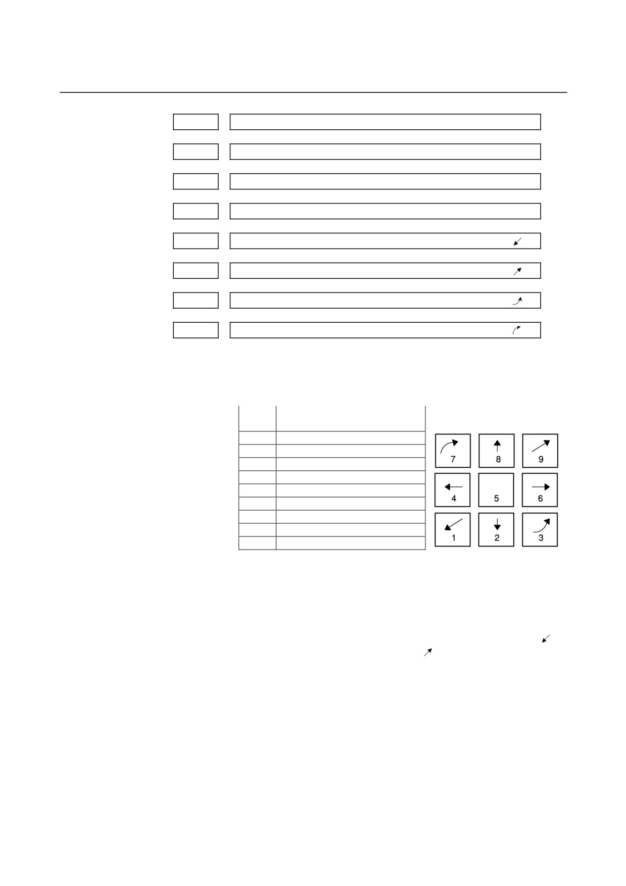
On software operator's panel, set a feed axis corresponding to an
arrow key on the MDI panel when jog feed is performed.
Set
Feed axis and direction
Arrow keys on the MDI panel
value
0
Not moved
1
First axis, positive direction
2
First axis, negative direction
3
Second axis, positive direction
4
Second axis, negative direction
5
Third axis, positive direction
6
Third axis, negative direction
7
Fourth axis, positive direction
8
Fourth axis, negative direction
[Example]
Under X, Y, and Z axis configuration, to set arrow keys to feed the
axes in the direction specified as follows, set the parameters to the
values given below. [8 ↑] to the positive direction of the Z axis, [2 ↓]
to the negative direction of the Z axis, [6 →] to the positive direction
of the X axis [4 ←] to the negative direction of the X axis, [1
] to
the positive direction of the Y axis, [9
] to the negative direction of
the Y axis
Parameter No.7210 = 5 (Z axis, positive direction)
Parameter No.7211 = 6 (Z axis, negative direction)
Parameter No.7212 = 1 (X axis, positive direction)
Parameter No.7213 = 2 (X axis, negative direction)
Parameter No.7214 = 3 (Y axis, positive direction)
Parameter No.7215 = 4 (Y axis, negative direction)
Parameter No.7216 = 0 (Not used)
Parameter No.7217 = 0 (Not used)
- 337 -
4.DESCRIPTION OF PARAMETERS
B-64120EN/01
7220
Name of general-purpose switch on software operator's panel
:
:
7283
Name of general-purpose switch on software operator's panel
[Data type] Byte
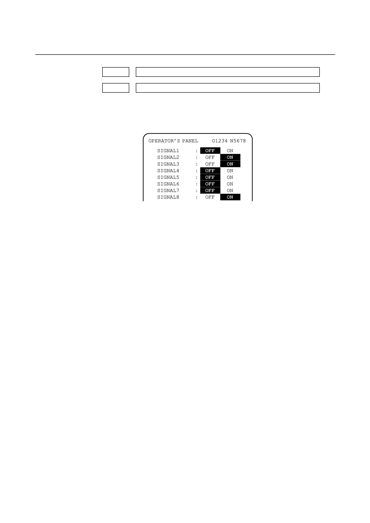
[Example] These parameters set the names of the general-purpose switches
(SIGNAL 1 through SIGNAL 8) on the software operator's panel as
described below.
These names are set using character codes that are displayed in
parameter Nos. 7220 to 7283.
Parameter No.7220:
Sets the character code (083) corresponding to S of SIGNAL 1.
Parameter No.7221:
Sets the character code (073) corresponding to I of SIGNAL 1.
Parameter No.7222:
Sets the character code (071) corresponding to G of SIGNAL 1.
Parameter No.7223:
Sets the character code (078) corresponding to N of SIGNAL 1.
Parameter No.7224:
Sets the character code (065) corresponding to A of SIGNAL 1.
Parameter No.7225:
Sets the character code (076) corresponding to L of SIGNAL 1.
Parameter No.7226:
Sets the character code
(032) corresponding to
(space) of
SIGNAL 1.
Parameter No.7227:
Sets the character code (049) corresponding to 1 of SIGNAL 1.
Parameter Nos. 7228 to 7235:
Set the character codes of SIGNAL 2 shown in the figure above.
Parameter Nos. 7236 to 7243:
Set the character codes of SIGNAL 3 shown in the figure above.
Parameter Nos. 7244 to 7251:
Set the character codes of SIGNAL 4 shown in the figure above.
Parameter Nos. 7252 to 7259:
Set the character codes of SIGNAL 5 shown in the figure above.
Parameter Nos. 7260 to 7267:
Set the character codes of SIGNAL 6 shown in the figure above.
Parameter Nos. 7268 to 7275:
Set the character codes of SIGNAL 7 shown in the figure above.
Parameter Nos. 7276 to 7283:
Set the character codes of SIGNAL 8 shown in the figure above.
The character codes are shown in Appendix A CHARACTER CODE
LIST.
- 338 -
B-64120EN/01
4.DESCRIPTION OF PARAMETERS
4.42
PARAMETERS OF PROGRAM RESTART
#7
#6
#5
#4
#3
#2
#1
#0
MOU
MOA
7300
MOU
MOA
SJG
[Data type]
Bit
SJG
Return feedrate in program restart operation
0 : Dry run feedrate
1 : Jog feedrate
MOA
In program restart operation, before movement to a machining restart
point after restart block search:
0 : The last M, S, T, and B codes are output.
1 : All M codes and the last S, T, and B codes are output.
NOTE
This parameter is enabled when the MOU
parameter is set to 1.
MOU
In program restart operation, before movement to a machining restart
point after restart block search:
0 : The M, S, T, and B codes are not output.
1 : The last M, S, T, and B codes are output.
7310
Movement sequence to program restart position
The following parameter can be set at "Setting screen".
[Data type]
Byte axis
[Valid data range]
1 to No. of controlled axes
This parameter sets the axis sequence when the machine moves to the
restart point by dry run after a program is restarted.
[Example]
The machine moves to the restart point in the order of the fourth,
first, second, and third axes one at a time when the first axis =
2, the second axis = 3, the third axis = 4, and the fourth axis = 1
are set.
- 339 -
4.DESCRIPTION OF PARAMETERS
B-64120EN/01
4.43
PARAMETERS OF POLYGON TURNING
#7
#6
#5
#4
#3
#2
#1
#0
PLZ
PQE
7600
[Data type]
Bit
PQE
The specification range of the rotation ratio for polygon turning
0 : P=1 to 9, Q=-9 to -1, 1 to 9
1 : P=1 to 999, Q=-999 to -1, 1 to 999
PLZ
Synchronous axis using G28 command
0: Returns to the reference position in the same sequence as the
manual reference position return.
1: Returns to the reference position by positioning at a rapid
traverse.
The synchronous axis returns to the reference position in the
same sequence as the manual reference position return when no
return-to-reference position is performed after the power is
turned on.
#7
#6
#5
#4
#3
#2
#1
#0
PLR
SBR
7603
[Data type]
Bit
SBR
For spindle synchronization, speed ratio control is:
0 : Disabled.
1 : Enabled.
NOTE
1 This parameter is used to set the slave spindle
speed to a multiple of the master spindle speed
when the spindle synchronization function is used.
2 This parameter is not related to the polygon turning
function.
3 The spindle synchronization option is needed.
4 Parameter Nos. 7635 and 7636 also need be set
up.
PLR
The machine coordinates of a tool axis for polygon turning are:
0 : Rounded by the setting in parameter 7620.
1 : Rounded by 360° (or the setting in parameter No. 1260 when bit
0 (ROA) of parameter No. 1008 is set to 1).
- 340 -
B-64120EN/01
4.DESCRIPTION OF PARAMETERS
Control axis number of tool rotation axis for polygon turning
7610
[Data type]
Byte
[Valid data range]
1, 2, 3, . . . number of control axes
This parameter sets the control axis number of a rotation tool axis
used for polygon turning.
Movement of tool rotation axis per revolution
7620
[Data type]
2-word
Input increment
IS-A
IS-B
IS-C
Unit
Rotation axis
0.01
0.001
0.0001
deg
[Valid data range]
1 to 9999999
This parameter sets the movement of a tool rotation axis per
revolution.
Maximum allowable speed for the tool rotation axis (polygon
7621
synchronization axis)
[Data type]
Word
[Unit of data]
min-1
[Valid data range]
0 to 1.2 × 10⁸ / Set value of the parameter No.7620
This parameter sets the maximum allowable speed of the tool rotation
axis (polygon synchronization axis).
If the speed of the tool rotation axis (polygon synchronization axis)
exceeds the specified maximum allowable speed during polygon
turning, the speed is clamped at the maximum allowable speed. When
the speed is clamped at a maximum allowable speed, however,
synchronization between the spindle and tool rotation axis (polygon
synchronization axis) is lost. And, when the speed is clamped, P/S
alarm No.5018 is issued.
Multiplier influencing the slave spindle speed
7635
[Data type]
Byte
[Unit of data]
Slave spindle (min-1)/master spindle (min-1)
[Valid data range]
1 to 9
Set up a multiplier that will act on the distance through which the
slave spindle is to move.
In speed ratio control, the relationship between the speeds of the
spindles is:
setting of parameter
Slave spindle speed
= master spindle speed
×
No. 7635
- 341 -

4.DESCRIPTION OF PARAMETERS
B-64120EN/01
NOTE
1 This parameter is used to set the slave spindle
speed to a multiple of the master spindle speed
when the spindle synchronization function is used.
2 This parameter is not related to the polygon turning
function.
3 The spindle synchronization control is needed.
4 Bit 2 (SBR) of parameter No. 7603 and parameter
No. 7636 must be set as well.
Upper limit of the slave spindle speed
7636
[Data type]
Word
[Unit of data]
min-1
[Valid data range]
1 to 19999
Specify a clamp speed for the slave spindle. If the slave spindle
speed calculated from the master spindle speed exceeds the specified
slave spindle clamp speed, the actual slave spindle speed is clamped at
this clamp speed. At the same time, the master spindle speed is
decreased to maintain a constant spindle rotation ratio.
NOTE
1 This parameter is used to set the slave spindle
speed to a multiple of the master spindle speed
when the spindle synchronization function is used.
2 This parameter is not related to the polygon turning
function.
3 The spindle synchronization control is needed.
4 Bit 2 (SBR) of parameter No. 7603 and parameter
No. 7635 must be set as well.
- 342 -
B-64120EN/01
4.DESCRIPTION OF PARAMETERS
4.44 PARAMETERS OF GENERAL-PURPOSE RETRACTION
#7
#6
#5
#4
#3
#2
#1
#0
7704
ACR
[Data type]
Bit
ACR
In advanced preview control, AI advanced preview control, or
AI
contour control mode, the general-purpose retraction function is:
0 : Not used.
1 : Used.
(See the description of parameter No. 7745.)
#7
#6
#5
#4
#3
#2
#1
#0
7730
RTRx
[Data type]
Bit axis
RTRx
Retraction function is:
0 : Disabled for each axis.
1 : Enabled for each axis.
7740
Feedrate during retraction for each axis
[Data type]
2-word axis
[Unit of data, valid data range]
Valid data range
Increment system
Units of data
IS-B
IS-C
Millimeter machine
1 mm/min
30 to 240000
6 to 100000
Inch machine
0.1 inch/min
30 to 96000
6 to 48000
This parameter sets the feedrate during retraction for each axis.
7741
Retracted distance for each axis
[Data type]
2-word axis
Unit of data
Increment system
IS-B
IS-C
Millimeter input
0.001 mm
0.0001 mm
Inch input
0.0001 inch
0.00001 inch
[Valid range]
-99999999 to 99999999
This parameter sets the retracted distance for each axis.
- 343 -

4.DESCRIPTION OF PARAMETERS
B-64120EN/01
7745
Time constant of linear acceleration/deceleration during retraction
[Data type] Word axis
[Unit of data] msec
[Valid range]
0 to 4000
This parameter is used to set the acceleration rate of linear
acceleration/deceleration performed during retraction by the
general-purpose retraction function. For each axis, set a time (time
constant) required to achieve the feedrate set in parameter No. 7740.
NOTE
This parameter is valid when bit 0 (ACR) of
parameter No. 7704 is set to 1.
- 344 -

B-64120EN/01
4.DESCRIPTION OF PARAMETERS
4.45
PARAMETERS OF AXIS CONTROL BY PMC
#7
#6
#5
#4
#3
#2
#1
#0
8001
SKE
AUX
NCC
RDE
OVE
MLE
[Data type]
Bit
MLE
Whether all axis machine lock signal MLK <G044#1> is valid for
PMC-controlled axes
0 : Valid
1 : Invalid
NOTE
Each-axis machine lock signals MLK1 to MLK8
<G108#0 to #7> are always valid, regardless of the
setting of this parameter.
OVE
Signals related to dry run and override used in PMC axis control
0: Same signals as those used for the CNC
(1) Feedrate override signals *FV0 to *FV7 <G012#0 to #7>
(2) Override cancellation signal OVC <G006#4>
(3) Rapid traverse override signals ROV1 and ROV2
<G014#0,#1>
(4) Dry run signal DRN <G046#7>
(5)
Rapid traverse selection signal RT <G019#7>
1: Signals specific to the PMC
(1) Feedrate override signals *FV0E to *FV7E <G151#0 to
#7>
(2) Override cancellation signal OVCE <G150#5>
(3) Rapid traverse override signals ROV1E and ROV2E
<G150#0,#1>
(4) Dry run signal DRNE <G150#7>
(5) Rapid traverse selection signal RTE <G150#6>
RDE
Whether dry run is valid for rapid traverse in PMC axis control
0 : Invalid
1 : Valid
NCC
When a travel command is issued for a PMC-controlled axis (selected
by a controlled-axis selection signal) according to the program:
0 : P/S alarm 139 is issued while the PMC controls the axis with an
axis control command. While the PMC does not control the axis,
a CNC command is enabled.
1 : P/S alarm 139 is issued unconditionally.
AUX
The number of bytes for the code of an auxiliary function (12H)
command to be output is
0 :
1 (0 to 255)
1 :
2 (0 to 65535)
SKE
Skip signal during axis control by the PMC
0 : Uses the same signal SKIP <X004#7> as CNC.
1 : Uses dedicated axis control signal ESKIP <X004#6> used by the
PMC.
- 345 -
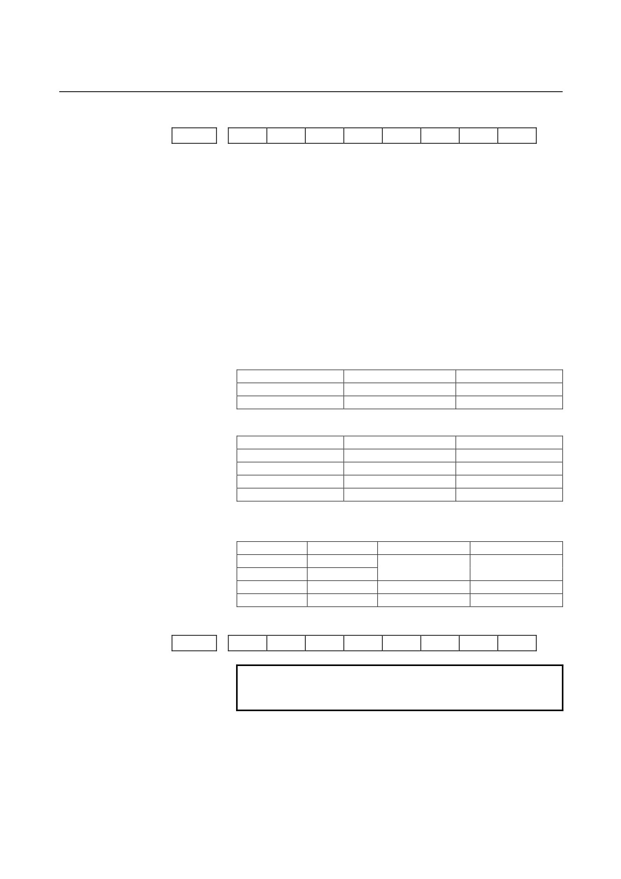
4.DESCRIPTION OF PARAMETERS
B-64120EN/01
#7
#6
#5
#4
#3
#2
#1
#0
8002
FR2
FR1
PF2
PF1
F10
SUE
DWE
RPD
[Data type]
Bit
RPD
Rapid traverse rate for PMC-controlled axes
0 : Feedrate specified with parameter No.1420
1 : Feedrate specified with the feedrate data in an axis control
command
DWE
Minimum time which can be specified in a dwell command in PMC
axis control when the increment system is IS-C
0 :
1 ms
1 :
0.1 ms
SUE
Whether acceleration/deceleration is performed for an axis that is
synchronized with external pulses, for external pulse synchronization
commands in PMC axis control
0 : Performed (exponential acceleration/deceleration)
1 : Not performed
F10
Least increment for the feedrate for cutting feed (per minute) in PMC
axis control
F10
Millimeter input
Inch input
0
1 mm/min
0.01 inch/min
1
10 mm/min
0.1 inch/min
PF1, PF2
Set the feedrate unit of feed per minute in PMC axis control
PF2
PF1
Feedrate unit
0
0
1/1
0
1
1/10
1
0
1/100
1
1
1/1000
FR1, FR2
Set the feedrate unit for feed per rotation for an axis controlled by the
PMC.
FR2
FR1
Millimeter input
Inch input
0
0
0.0001 mm/rev
0.000001 inch/rev
1
1
0
1
0.001 mm/rev
0.00001 inch/rev
1
1
0.01 mm/rev
0.0001 inch/rev
#7
#6
#5
#4
#3
#2
#1
#0
8003
PAX
PIM
NOTE
When this parameter is set, the power must be
turned off before operation is continued.
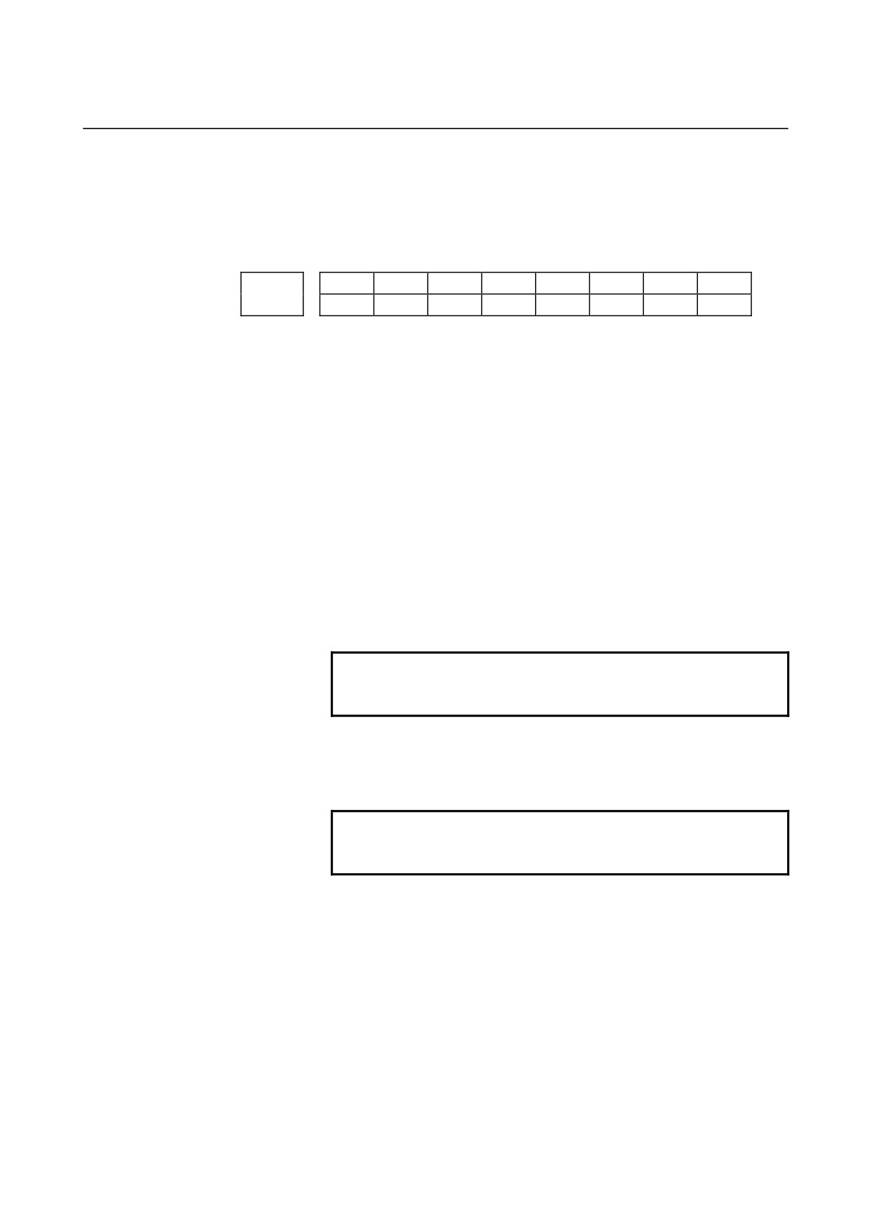
[Data type]
Bit
PIM
Specifies whether to cause an inch/metric input to affect the linear axis
that is subjected only to PMC axis control
(see the parameter
No.1010), as follows:
0: To affect.
1: Not to affect.
- 346 -
B-64120EN/01
4.DESCRIPTION OF PARAMETERS
PAX
When the number of CNC-controlled axes (parameter No. 1010) is set
to 0:
0 : All axes are assumed to be CNC axes.
1 : All axes are assumed to be PMC axes.
#7
#6
#5
#4
#3
#2
#1
#0
NDI
NCI
DSL
NMT
CMV
8004
NDI
NCI
DSL
G8R
G8C
NMT
CMV
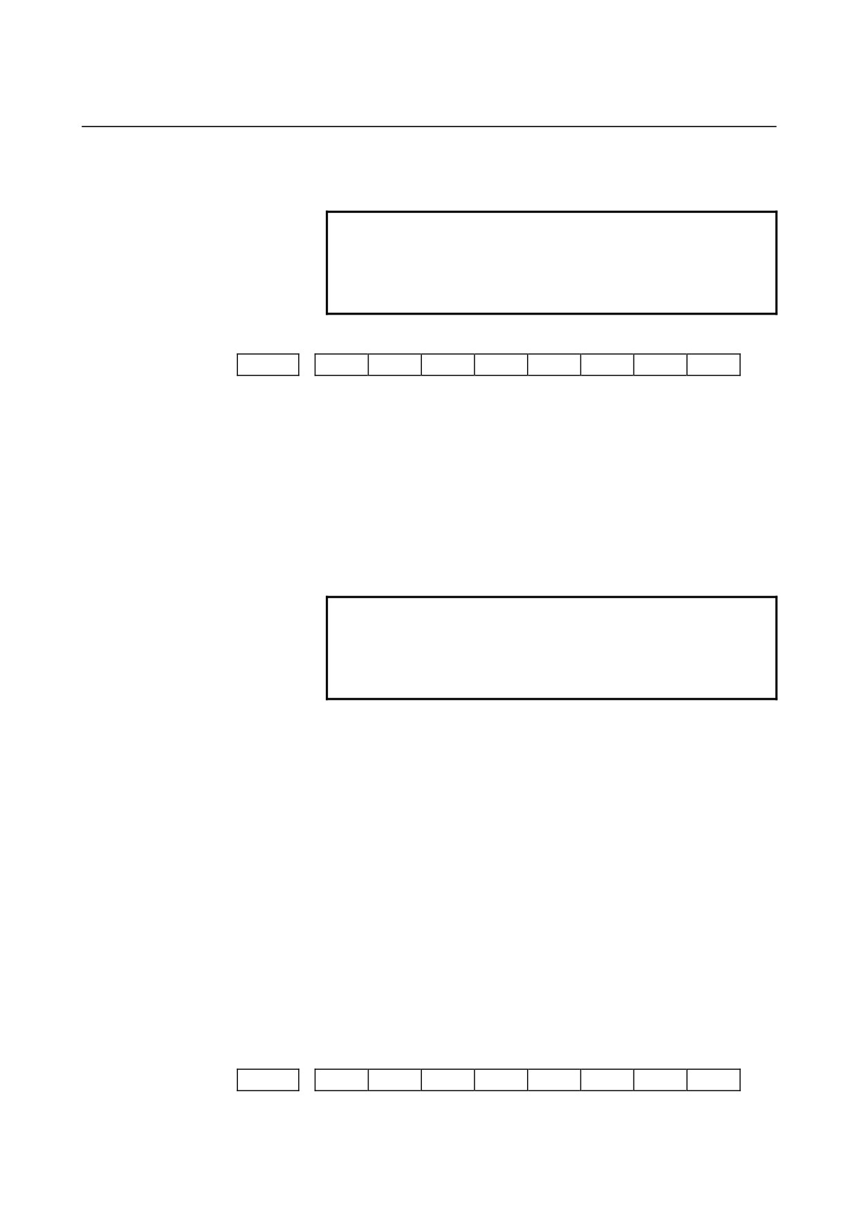
[Data type]
Bit
CMV
When a move command and auxiliary function are specified from the
CNC, and the system is awaiting the auxiliary function completion
signal after completion of the specified axis movement:
0 : An alarm (No.130) is issued when an axis control command is
issued from the PMC for the same axis.
1 : An axis control command, when issued from the PMC for the
same axis, is executed.
NMT
When a command is specified from the CNC for the axis on which the
tool is moving according to axis control specification from the PMC:
0 : P/S alarm No.130 is issued.
1 : The command is executed without issuing an alarm, provided the
command does not involve a movement on the axis.
G8C
Advanced preview control for the axes controlled by the PMC is:
0 : Disabled.
1 : Enabled.
NOTE
This parameter is valid for an axis for which bit 7
(NAHx) of parameter No.1819 is set to 0.
G8R
Advanced preview control over axes controlled by the PMC is:
0 : Enabled for cutting feed (disabled for rapid traverse).
1 : Enabled for both cutting feed and rapid traverse.
NOTE
This parameter is valid for an axis for which bit 7
(NAHx) of parameter No.1819 is set to 0.
DSL
If the selection of an axis is changed when PMC axis selection is
disabled:
0 : P/S alarm No.139 is issued.
1 : The change is valid, and no alarm is issued for an unspecified
system.
NCI
In axis control by the PMC, a position check at the time of
deceleration is:
0 : Performed.
1 : Not performed.
NDI
For PMC axis control, when diameter programming is specified for a
PMC-controlled axis:
0 : The amount of travel and feedrate are each specified with a
radius.
- 347 -
4.DESCRIPTION OF PARAMETERS
B-64120EN/01
1 : The amount of travel and feedrate are each specified with a
diameter.
NOTE
NDI is valid for an axis for which diameter
programming is specified (bit 3 (DIAx) of parameter
No. 1006 is set to 1) when bit 1 (CDI) of parameter
No. 8005 is set to 0.
#7
#6
#5
#4
#3
#2
#1
#0
8005
MFD
IFV
PVP
DRR
R10
CDI
EDC
[Data type]
Bit
EDC
In PMC-based axis control, an external deceleration signal is:
0 : Disabled.
1 : Enabled.
CDI
For PMC axis control, when diameter programming is specified for a
PMC-controlled axis:
0 : The amount of travel and feedrate are each specified with a
radius.
1 : The amount of travel is specified with a diameter while the
feedrate is specified with a radius.
NOTE
1 This parameter is valid when bit 3 (DIA) of
parameter No.1006 is set to 1.
2 When CDI is set to 1, bit 7 (NDI) of parameter
No.8004 is disabled.
R10
When the RPD parameter (bit 0 of parameter No.8002) is set to 1, the
unit for specifying a rapid traverse rate for the PMC axis is:
0 :
1 mm/min.
1 :
10 mm/min.
DRR
For cutting feed per rotation in PMC axis control, the dry run function
is:
0 : Disabled.
1 : Enabled.
PVP
For velocity command in PMC axis control, position control is:
0 : Not performed.
1 : Performed.
IFV
Override for each group in PMC axis control is:
0 : Disabled.
1 : Enabled.
MFD
Output by each auxiliary function of the PMC axis control function is:
0 : Disabled.
1 : Enabled.
#7
#6
#5
#4
#3
#2
#1
#0
8006
EAL
EZR
ESI
IPA
EML
- 348 -
B-64120EN/01
4.DESCRIPTION OF PARAMETERS
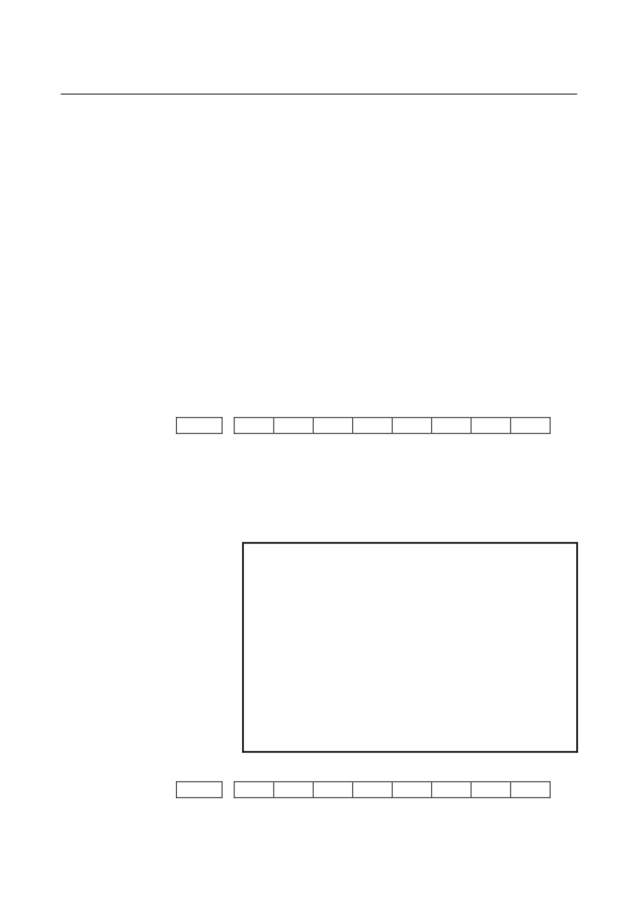
[Data type]
Bit
EML
When bit 0 (MLE) of parameter No. 8001 is set to 1, for PMC axes:
0 : The all axis machine lock signal and axis-by-axis machine lock
signals are disabled.
1 : The all axis machine lock signal is disabled and the axis-by-axis
machine lock signals are enabled.
IPA
For controlled axis at PMC axis control only
(see the parameter
No.1010) :
0 : The in-position check is performed when no move command is
issued for the PMC axis.
1 : No in-position check is always performed.
EZR
For PMC axes, the setting of bit 0 (ZRN) of parameter No. 1005 is:
0 : Not followed. (Constant checking of the reference position return
status is not made.)
1 : Followed.
(The reference position return status is checked
according to the setting of bit 0 (ZRN) of parameter No. 1005.)
EAL
In axis control by the PMC, the function that allows the alarm signal
(EIALg) to be reset by a CNC reset operation is:
0 : Disabled.
1 : Enabled.
#7
#6
#5
#4
#3
#2
#1
#0
8007
NIS
[Data type]
Bit
NIS
In the in-position check of PMC axes, in-position check disable signal
NOINPS
<G023#5> and in-position check disable signals for
individual axes NOINP1 to NOINP8 <G359> are:
0 : Invalid.
1 : Valid.
NOTE
Although in-position checks of ordinary blocks can
be disabled by using in-position check disable
signal NOINPS <G023#5> and in-position check
disable signals for individual axes NOINP1 to
NOINP8 <G359>, the in-position check at the
reference position obtained by a reference position
return operation (G28 or G30) is always performed.
The in-position check at an intermediate point,
however, can be disabled. To disable the
in-position check at the reference position as well,
set bit 0 (RF2) of parameter No. 3454 to 1, and
specify a reference position return by using G28.2
or G30.2.
#7
#6
#5
#4
#3
#2
#1
#0
8008
MIRx
[Data type]
Bit axis
- 349 -
4.DESCRIPTION OF PARAMETERS
B-64120EN/01
MIRx
When a PMC axis control command is issued in mirror image mode,
the mirror image is:
0 : Not considered.
1 : Considered.
This parameter is valid when PMC signals MI1 to MI4 <G106#0-3>
are set to "1" or bit 0 (MIRx) of parameter No. 0012 is set to "1".
8010
Selection of the DI/DO group for each axis controlled by the PMC
[Data type]
Byte axis
[Valid data range]
1 to 4
Specify the DI/DO group to be used to specify a command for each
PMC-controlled axis.
Value
Description
1
DI/DO group A (G142 to G153) is used.
2
DI/DO group B (G154 to G165) is used.
3
DI/DO group C (G166 to G177) is used.
4
DI/DO group D (G178 to G189) is used.
8020
Low-speed feedrate at reference position return in axis control by PMC (FL)
[Data type]
Word axis
[Unit of data, valid data range]
Valid data range
Increment system
Units of data
IS-B
IS-C
Millimeter machine
1 mm/min
6 to 15000
6 to 12000
Inch machine
0.1 inch/min
6 to 6000
6 to 4800
Rotation axis
1 deg/min
6 to 15000
6 to 12000
This parameter specifies the low-speed feedrate at a reference position
return on a PMC-controlled axis (FL).
NOTE
If 0 is specified, the value of parameter No. 1425 is
used.
- 350 -
B-64120EN/01
4.DESCRIPTION OF PARAMETERS
8021
Minimum speed of rapid traverse override in axis control by PMC (Fo)
[Data type]
Word axis
[Unit of data, valid data range]
Valid data range
Increment system
Units of data
IS-B
IS-C
Millimeter machine
1 mm/min
6 to 15000
6 to 12000
Inch machine
0.1 inch/min
6 to 6000
6 to 4800
Rotation axis
1 deg/min
6 to 15000
6 to 12000
This parameter specifies the minimum speed of rapid traverse override
on a PMC-controlled axis (Fo).
8022
Upper-limit rate of feed per revolution during PMC axis control
[Data type]
Word
[Unit of data, valid data range]
Valid data range
Increment system
Units of data
IS-B
IS-C
Millimeter machine
1 mm/min
6 to 15000
6 to 12000
Inch machine
0.1 inch/min
6 to 6000
6 to 4800
Rotation axis
1 deg/min
6 to 15000
6 to 12000
This parameter sets the upper limit rate of feed per revolution during
PMC axis control.
NOTE
The upper limit specified for the first axis is valid for
all axes. The specifications for the second and
subsequent axes are ignored.
Linear acceleration/deceleration time constant for speed commands for PMC
8028
axis control
[Data type] Word axis
[Unit of data] ms/1000 min-1
[Valid data range]
0 to 32767
This parameter sets the time required for the servo motor rotation
speed to increase or decrease by 1000 min-1, for each axis, as a linear
acceleration/deceleration time constant for speed commands for PMC
axis control. (See also the description of bit 6 (JVB) of parameter No.
8003.)
NOTE
If this parameter is set to 0,
acceleration/deceleration control is not applied.
- 351 -