FANUC Series 90-30 PLC. Installation and Hardware Manual (GFK-0356Q) - page 13

B
Example of Cable Configurations
Examples of cable configurations required when using the converter can be found in Appendix C.
Specifications for the converter are shown in the following table.
Table B-4. Specifications for IC690ACC900 Converter
Power Requirements:
Voltage
5 volts DC, +5%
Current
170 mA, ±5%
RS-422/RS-485 Interface Cables:
Maximum cable length
1000 feet(300m)
Cable Type: *
6 feet (2m)
Cable type: Belden 9508, AWG #24 (0.22 mm2)
30 feet (10m) **
Cable type: Belden 9309, AWG #22 (0.36 mm2)
≥30 feet, up to 1000 feet (300m) ]
Same cable as for 30 feet.
Connector Type
15-pin D-type Male Subminiature (both ends)
RS-232 Interface Cable:
Maximum cable length
50 feet (15m)
Up to 50 feet (15m)
Connector Type
25-pin D-type Female Subminiature (converter end) 9-pin, 15-pin, or
25-pin (depending on type of connector on your serial device) D-type
Female Subminiature (programming device end)
* Catalog numbers are provided as suggestions only. Any cable having the same electrical
characteristics is acceptable. It is strongly recommended that you use stranded wire. Since it
is sometimes hard to find a cable with the desired number of twisted pairs (the Belden 9309
has an extra pair), you may end up with a cable with extra pairs.
** For distances over 10 feet, the +5 volt DC logic power source must be provided externally by
connecting an external power supply to the +5V and SG (0V) connections at the converter end
of the cable. The +5V pin at the PLC connector end of the cable must not be connected to
the cable. The +5V and SG connections from the external power supply must be isolated from
its own power line ground connection. Ensure that there is no connection between the external
supply and the PLC except the SG cable connection.
GFK-0356Q
Appendix B IC690ACC900 Converter
B-9
Appendix
IC655CCM690 Isolated Repeater/Converter
C
Note: This product is no longer available. This appendix is for reference by
those already using this product. It has been replaced by catalog number
IC690ACC903 (see Appendix E for details).
This appendix describes how to use the Isolated Repeater/Converter (IC655CCM590) with Series
90 PLCs. The following topics are covered in this appendix.
■ Description of the Isolated Repeater/Converter
■ System Configurations
■ Cable Diagrams
Note: The catalog number for the Isolated Repeater/Converter was previously
IC630CCM390.
Description of the Isolated Repeater/Converter
The Isolated Repeater/Converter (IC655CCM590) can be used for the following purposes.
■ To provide ground isolation where a common ground cannot be established between
components.
■ To boost RS-422 signals for greater distance and more drops.
■ To convert signals from RS-232 to RS-422 or RS-422 to RS-232.
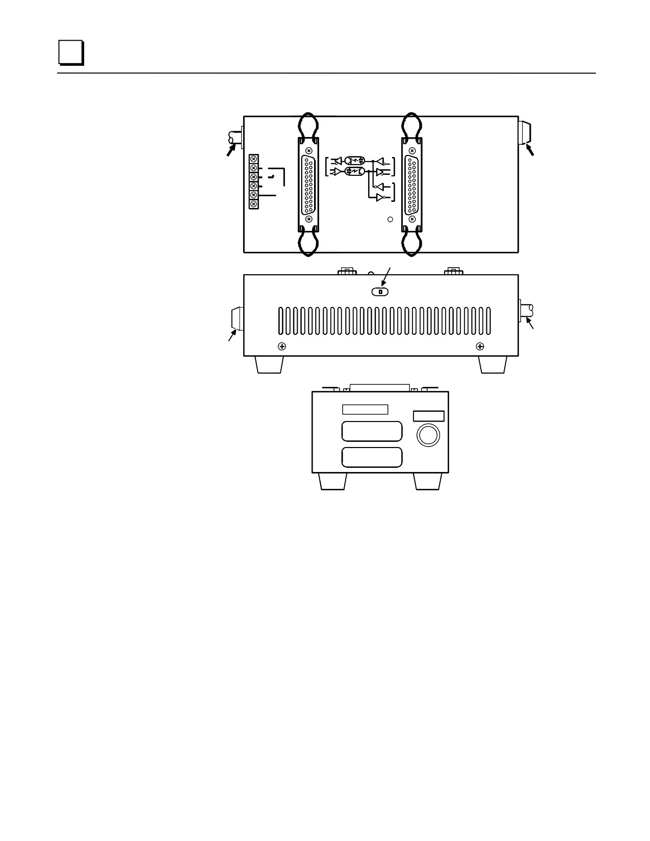
The figure on the next page shows the appearance of the unit and the locations of key features.
GFK-0356Q
C-1
C
(TOP VIEW)
RS422
RS422
POWER
GE Fanuc
FUSE
CORD
H
115VAC
N
RS232C
230VAC
N
G
ISOLATED
ADAPTOR
POWER
J1
J2
SWITCH
POWER
CORD
FUSE
(BACK
VIEW)
FUSE-1AMP
(SIDE
VIEW)
Figure C-1. Isolated/Repeater Converter
Items of interest to the user on the Isolated Repeater/Converter are described below.
Two 25-pin female D-type connectors (Two 25-pin male, D-type connectors (solder pot), are
included for user cabling.)
115/230 VAC power connection (internal) 4-position terminal block.
Fused 1 Amp power protection.
Power ON (green) indicator LED.
Three-position toggle switch, recessed in the back of the unit, is set according to the system
configurations shown later in this appendix.
C-2
Series 90-30 PLC Installation and Hardware Manual - August 2002
GFK-0356Q
IC655CCM590 Converter
C
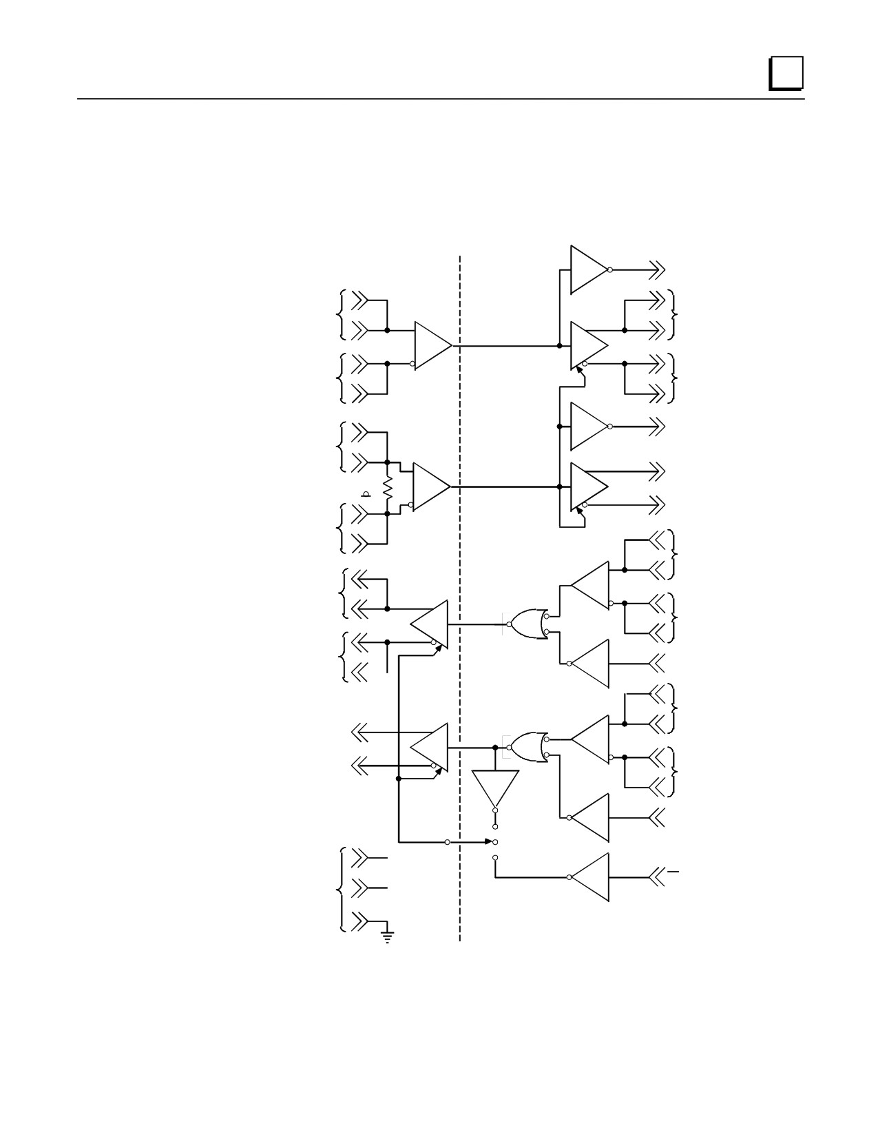
Logic Diagram of the Isolated Repeater/Converter
The figure below provides a functional look at the unit. Note the 3-position switch for controlling
the J1 port transmitters. This switch is discussed in System Configurations later in this appendix..
OPTICAL
RS-422/RS-232C
RS-422
ISOLATION
J2
J1
2
SD (RS-232C)
22
22
RD ( B' )
SD (B )
14
14
15
15
RD ( A' )
SD (A )
23
23
4
8
RTS (RS-232C)
CTS ( B' )
10
10
RTS (B )
RESISTOR
150
11
11
RTS (A )
CTS ( A' )
19
9
RD ( B' )
17
25
SD ( B )
16
17
RD ( A' )
18
16
3
SD ( A )
24
RD (RS-232C)
8
CTS ( B' )
12
12
RTS (B )
13
13
RTS (A )
CTS ( A ')
9
5
CTS (RS-232C)
( CTS)
(ON)
(SE)
ISOLATED
25
POWER
SUPPLIES
SE (RS-232C)
115
VAC
Figure C-2. RS-422 Isolated Repeater/RS-232 Converter Logic Diagram
Note: All inputs are biased to the inactive state. Inputs left unconnected will produce a binary 1
(OFF) state on the corresponding output.
GFK-0356Q
Appendix C IC655CCM690 Isolated Repeater/Converter
C-3
C
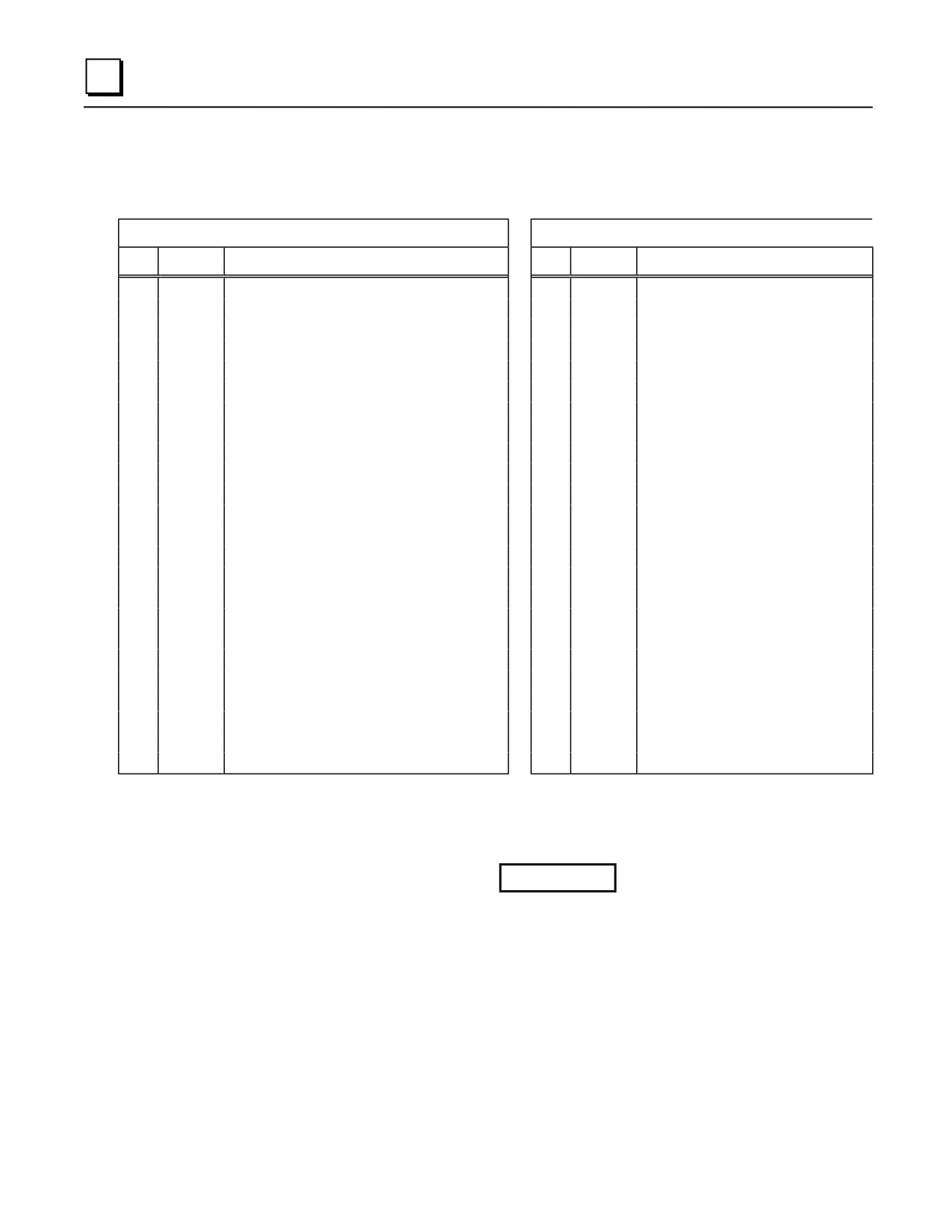
Pin Assignments for the Isolated Repeater/Converter
Table C-1. Isolated Repeater/Converter Pin Assignments
J1 RS-422 Port (25-pin female connector)
J2 RS-422/RS-232 Port (25-pin female connector)
Pin
Signal
Description
Pin
Signal
Description
1
NC
1
NC
2
NC
2
SD
Send Data (RS-232)
3
NC
3
RD
Receive Data (RS-232)
4
NC
4
RTS
Request to Send (RS-232)
5
NC
5
CTS
Clear to Send (RS-232)
6
NC
6
NC
7
0V
Ground Connection
7
0V
Ground Connection
8
CTS(B’)
Clear to Send (Optional Termination)
8
CTS(B’)
Clear to Send Optional Termination)
9
CTS(A’)
Clear to Send (Optional Termination)
9
CTS(A’)
Clear to Send (Optional Termination)
10
CTS(B’)
Clear to Send
10
RTS(B)
Request to Send
11
CTS(A’)
Clear to Send
11
RTS(A)
Request to Send
12
RTS(B)
Request to Send
12
CTS(B’)
Clear to Send
13
RTS(A)
Request to Send
13
CTS(A’)
Clear to Send
14
RD(B’)
Receive Data
14
SD(B)
Send Data
15
RD(A’)
Receive Data
15
SD(A)
Send Data
16
SD(A)
Send Data
16
RD(A’)
Receive Data
17
SD(B)
Send Data
17
RD(B’)
Receive Data
18
NC
18
RD(A’)
Receive Data (Optional Termination)
19
NC
19
RD(B’)
Receive Data (Optional Termination)
20
NC
20
NC
21
NC
21
NC
22
RD(B’)
Receive Data
22
SD(B)
Send Data (Optional Termination)
23
RD(A’)
Receive Data
23
SD(A)
Send Data (Optional Termination)
24
SD(A)
Send Data
24
NC
NC=No Connection
SD (Send Data) and RD (Receive Data) are the same as TXD and RXD (used in the Series Six PLC).
(A) and (B) are the same as - and + A and B denote outputs, and A’ and B’ denote inputs.
Caution
The signal ground connections (pin 7 on each connector) must be made
between the Isolated Repeater/Converter and the PLC for J1, and the
Isolated Repeater/Converter and the host computer for J2.
Pin 7 of the J1 port is connected to the metal shell of the J1 connector. Pin 7
of the J2 port is connected to the metal shell of the J2 connector. These two
signal ground connections are isolated from each other and from the power
system ground (green wire on the terminal block). To maintain proper
isolation, these signal grounds cannot be tied together.
C-4
Series 90-30 PLC Installation and Hardware Manual - August 2002
GFK-0356Q
IC655CCM590 Converter
C
RS-232
RS-422 ISOLATED REPEATER
RS-422
a44783
SHIELDED
RS-232 CONVERTER
TWISTED SHIELDED
PAIRS
(IC655CCM590)
PAIRS
J2
J1
PIN
PIN
PIN
PIN
150 Ω
TD
3
RD
RD (B')A' )22
2
SD ( A )
RD
2
SD
**
RD (A')B' )23
3
SD ( B )
RTS
5
CTS
SD ( A )15
12
RD ( A' )
CTS
4
RTS
SD ( B )14
13
RD ( B' )
DCD
7
GND
CTS ( A' )16
10
RT
SERIES
DTR
CTS ( B' )17
11
RTS ( A )
90 PLC
HOST
GND
RTS ( A )
9
RTS ( B )
11
RS-422
COMPUTER
RTS ( B )10
6
CTS ( A' )
PORT
13
14
CTS ( B' )
12
15
0V
7
8
SHLD
7
1
0V
25-PIN
25-PIN
25-PIN
25- PIN
15- PIN
15- PIN
MALE
FEMALE
FEMALE
MALE
MALE
FEMALE
RS-232/
RS-422
RS-422
PORT
** SWITCH IN CENTER POSITION
PORT
115VAC
TERMINATION RESISTANCE FOR THE RECEIVE DATA (RD) SIGNAL NEEDS TO BE CONNECTED ONLY ON UNITS AT THE END OF THE LINES.
* THIS TERMINATION IS MADE ON THE SERIES 90 PLC PRODUCTS BY CONNECTING A JUMPER BETWEEN PIN 9 AND PIN 10 INSIDE THE
15-PIN D-SHELL WITH THE FOLLOWING EXCEPTION. FOR SERIES 90-70 PLCs, CATALOG NUMBERS IC697CPU731 AND IC697CPU771,
THE TERMINATION FOR RD AT THE PLC IS IMPLEMENTED BY A JUMPER BETWEEN PIN 9 AND PIN 11.
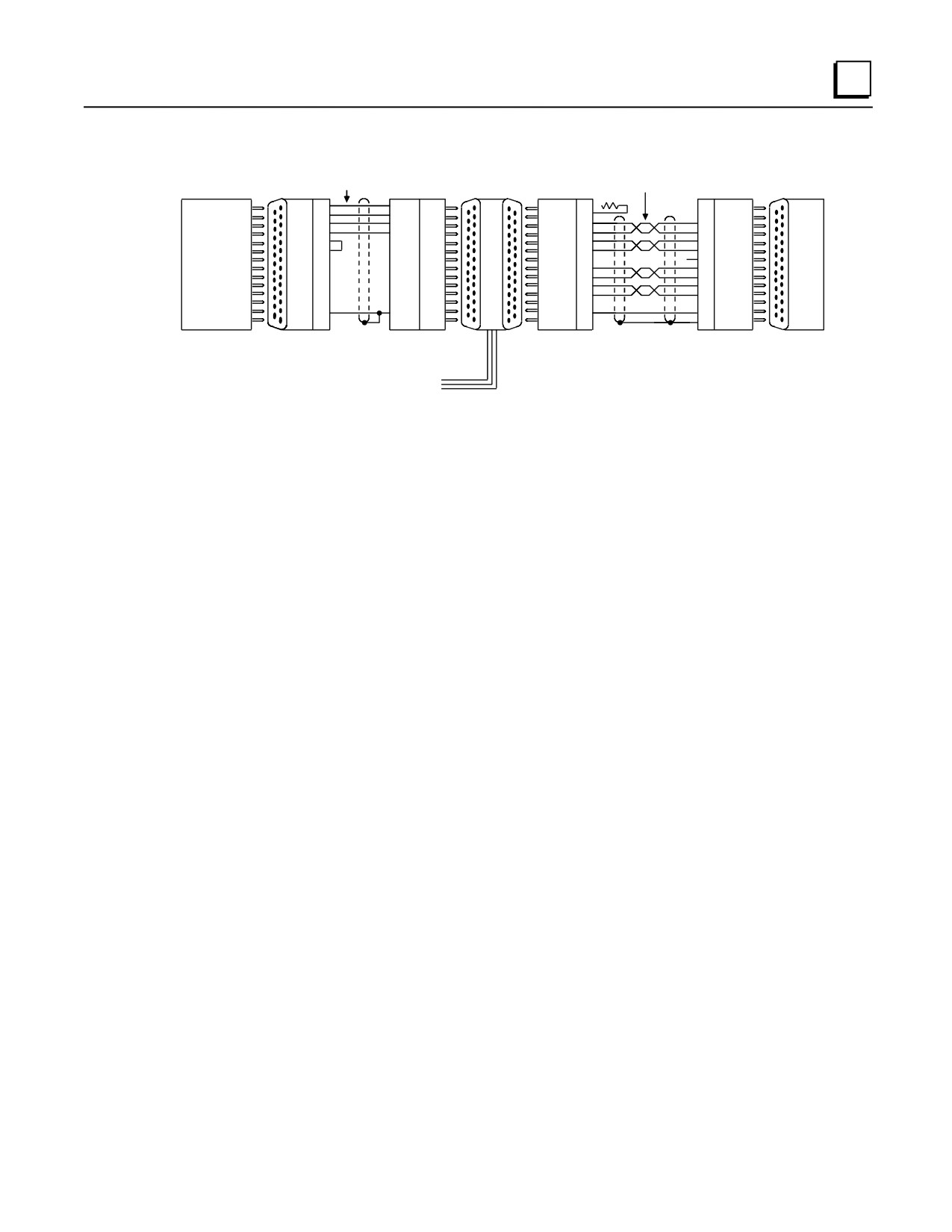
Figure C-3. Example RS-422 Isolated Repeater/RS-232 Converter Connection
System Configurations
The figures below show various ways you can connect the Isolated Repeater/Converter to convert
signals, expand the number of drops, and obtain greater distance. Any system configuration can be
reduced to a minimum number of cables each covering a part of the overall system configuration.
The following examples of system configurations refer to these cables as Cables A through E
which are described in Cable Diagrams later in this section.
Downstream and Upstream Contention. In this section, simple multidrop configurations are
those where a single Isolated Repeater/Converter is used. Complex multidrop configurations
contain one or more multidrop sections where an Isolated Repeater/Converter is included as one
of the drops. In both simple and complex multidrop configurations, the transmitters directed
downstream from the master can be on at all times. There will be no contention for the
communication line because only one device (the master) transmits downstream.
In simple multidrop configurations, there will be no contention when transmitting upstream as long
as devices tri-state their drivers when idle and turn them on only when they have something to
transmit. This is the case for the Series 90-70 and Series 90-30 CMMs.
In complex multidrop configurations, however, special steps must be taken to switch the upstream
transmitters of the Isolated Repeater/Converter.
Switching Upstream Transmitters. For the RS-422 drivers to be active at the J2 port of the
Isolated Repeater/Converter, the RTS input at J1 must be true. The state of the RS-422 drivers at
the J1 port depends on the position of the switch on the unit. When the switch is in the center
position, the J1 transmitters will always be turned on. When the switch is in the CTS position,
(toward the power cable), then either the RS-232 or RS-422 CTS signal must be true to turn on the
J1 drivers.
Note: Note the position of the switch on the Isolated/Repeater Converter in the system
configurations below.
GFK-0356Q
Appendix C IC655CCM690 Isolated Repeater/Converter
C-5
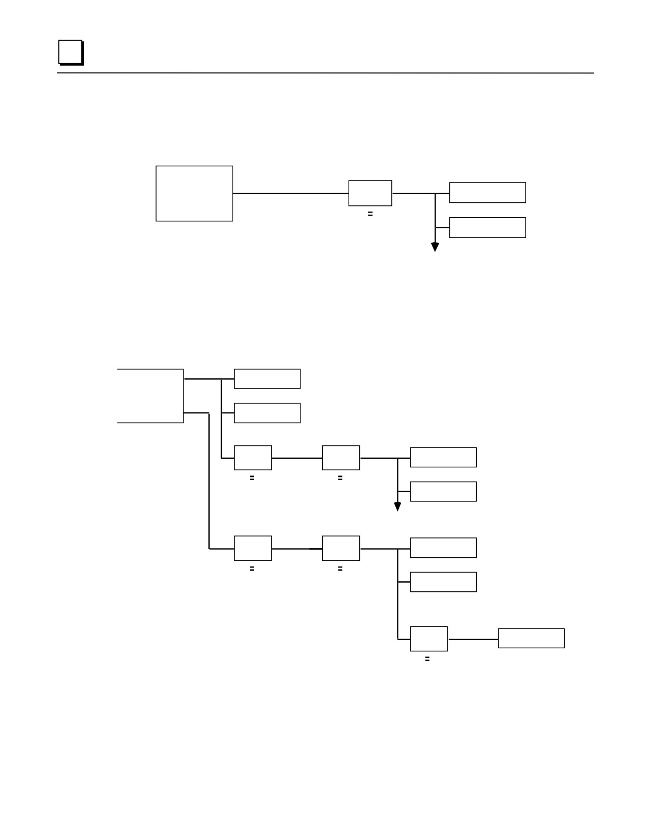
C
Simple Multidrop Configuration
This configuration shows how to connect a single Isolated Repeater/Converter for signal
conversion or greater distance.
RS-232
RS-422
RS-422
(CABLE A)
(CABLE B)
(CABLE D)
SERIES 90 PLC
OR
* BRICK
SERIES 90 PLC
HOST
J2
J1
SW
ON
SERIES 90 PLC
* BRICK IS THE NICKNAME FOR THE
ISOLATED REPEATER/CONVERTER
Figure C-4. Simple System Configuration Using the Isolated Repeater/Converter
Complex Multidrop Configuration
This configuration shows how to connect multiple Isolated Repeater/Converters for signal
conversion, greater distance, and more drops.
RS-422
(CABLE
C)
SERIES 90
SERIES 90
C
C OR
HOST
SERIES 90
C
RS-422
RS-422
(CABLE
(CABLE
D)
D)
BRICK
BRICK
SERIES 90
J2
J1
J2
J1
PLC
RS-232
SWON
SWON
(CABLE
SERIES 90
)
C
RS-422
(CABLE
B)
RS-422
RS-422
(CABLE
(CABLE
D)
D)
SERIES 90
BRICK
BRICK
J2
J1
J2
J1
C
SWON
SWON
SERIES 90
PLC
RS-232
(CABLE
* BRICK IS THE NICKNAME FOR THE
BRICK
)
SERIES 90
ISOLATED REPEATER/CONVERTER
J1
J2
PLC
SW
CTS
Figure C-5. Complex System Configuration Using the Isolated Repeater/Converter
C-6
Series 90-30 PLC Installation and Hardware Manual - August 2002
GFK-0356Q
IC655CCM590 Converter
C
Rules for Using Repeater/Converters in Complex Networks
When designing a complex multidrop network including PLCs and RS-422 repeater/converters
(bricks), the following rules apply:
Rule 1: When using a brick as a repeater, port J2 should always be directed toward the host
device, and Port J1 should always be directed away from the host device. The switch located on
the side of the brick should always be in the center position (ON). The only case in which Port J1
is directed toward the host is when the brick is used as a converter (RS-232) at the slave. The
switch is in the right position (CTS).
Rule 2: If a Series 90 CMM slave device is located downstream of a brick, set the configuration of
the CMM serial port to NONE flow control with a 10 ms Modem Turnaround Delay (Applies to
CCM, SNP, and SNP-X protocols only).
Rule 3: Do not place more than three bricks in a single communication path between the host and
the slave devices.
GFK-0356Q
Appendix C IC655CCM690 Isolated Repeater/Converter
C-7
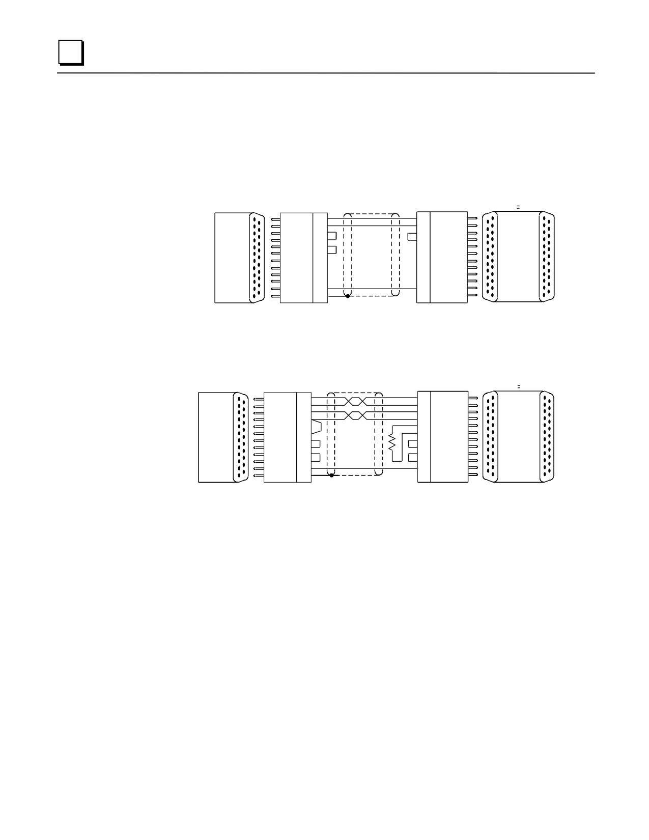
C
Cable Diagrams
The cable diagrams below are referred to as Cables A-E from the system configurations in the
previous figures. These diagrams show the principles for constructing your own cables and can be
modified to fit your specific application.
a44929
J2
J1
PIN
PIN
SW ON
TD
2
3
RD
RD
3
2
SD
RTS
4
4
RTS
CTS
5
5
CTS
SERIES 90
DCD
8
7
GND
DTR
20
ISOLATED
CMM
REPEATER/
PORT
GND
7
CONVERTER
1 OR 2
SHLD
1
(BRICK)
25- PIN
25- PIN
25- PIN
25- PIN
FEMALE
MALE
MALE
FEMALE
Figure C-6. Cable A; RS-232 CMM To Converter
a44930
J2
SW ON
J1
PIN
PIN
SD (A)
9
16
RD (A')
SD (B)
21
17
RD (B')
RD (A')
13
15
SD (A)
RD (B')
25
14
SD (B)
12
19
RTS (B)
SERIES 90
RTS (A)
24
18
CTS (B')
ISOLATED
CMM
TERMA')
10
10
TERM)
REPEATER/
PORT
TERMB)
11
12
TERM')
CONVERTER
1 OR 2
CTS (B')
22
11
GND
(BRICK)
GND
23
13
SHLD
7
7
1
25- PIN
25- PIN
25- PIN
25- PIN
FEMALE
MALE
MALE
FEMALE
ON THE ISOLATED REPEATER/CONVERTER, INSTALL 150 OHM RESISTOR (SUPPLIED).
* TERMINATE CONNECTION: ON THE CMM, INSTALL JUMPER TO CONNECT INTERNAL 120 OHM RESISTOR.
Figure C-7. Cable B; RS-422 CMM To Converter
C-8
Series 90-30 PLC Installation and Hardware Manual - August 2002
GFK-0356Q
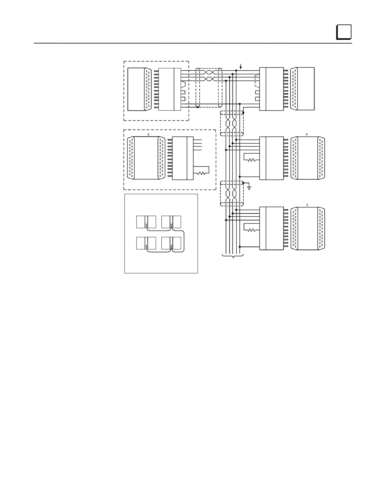
IC655CCM590 Converter
C
SUBSTITUTE APPROPRIATE UP STREAM DEVICE
(WITHIN DOTTED BOX) PER SYSTEM DIAGRAMS.
MAKE CONNECTIONS
SHIELDED
TWISTED
INSIDE D-CONNECTORS
PIN
PAIRS
PIN
SD (A)
9
13
RD (A')
SD (B)
21
25
RD (B')
SERIES 90
RD (A')
13
9
SD (A)
CMM
RD (B')
25
21
SD (B)
SERIES 90
PORT
12
12
TERM
CMM
1 OR 2
TERMA)
24
24
TERM
PORT
TERMA')
10
*
10
RTS (A)
I
RTS (B)
11
11
CTS (A')
OR
CTS (B')
22
22
RTS (B)
2
GND
23
23
CTS (B')
SHLD
7
7
0V
**
1
1
SHLD
25- PIN
25- PIN
25- PIN
25- PIN
FEMALE
MALE
MALE
FEMALE
J2
SW
ON
J1
PIN
PIN
J1
SW
CTS
J2
SD (A)
16
15
RD (A')
SD (B)
17
14
RD (B')
RD (A')
15
16
SD (A)
RD (B')
14
17
SD (B)
RTS (B)
12
22
TERM
ISOLATED
ISOLATED
REPEATER/
REPEATER/
CTS (B')
10
23
TERM
CONVERTER
CONVERTER
RTS (A)
13
150 OHMS
7
GND
(BRICK)
CTS (A')
11
(USED AS A
(BRICK)
TERM
22
TERM
23
CONVERTER)
GND
7
150 OHMS
25- PIN
25- PIN
25- PIN
25- PIN
FEMALE
MALE
MALE
FEMALE
NOTE
WHEN WIRING RS-422 /485 MULTIDROP
REFLECTIONS ON THE TRANSMISSION LINE
J2
SW
J1
REDUCED BY CONFIGURING THE CABLE IN A
PIN
ON
J
CHAIN FASHION AS SHOWN
1
16
RD (A')
MASTER
CMM SLAVE 1
17
RD (B')
15
SD (A)
14
SD (B)
ISOLATED
19
TERM
REPEATER/
18
TERM
CONVERTER
150 OHMS
7
GND
(BRICK)
(USED AS A
CPU BUILT-IN PORT CMM SLAVE 2
REPEATER)
25- PIN
25- PIN
ALSO IT IS RECOMMENDED TO MAKE ANY
MALE
FEMALE
CONNECTIONS INSIDE THE CABLE CONNECTOR
MOUNTED ON THE CMM. IT IS NOT
TO OTHER DEVICES
USE TERMINAL STRIPS OR OTHER TYPES
(MAXIMUM OF 8 DEVICES ON A MULTIDROP)
CONNECTORS ALONG THE LENGTH OF
TERMINATE THE RD (B') SIGNAL ONLY AT END
TRANSMISSION
OF MULTIDROP CABLE
TERMINATE CONNECTION ON FIRST AND LAST DROPS ONLY: ON THE CMM, INSTALL JUMPER TO CONNECT INTERNAL 120 OHM
RESISTOR. ON THE ISOLATED REPEATER/CONVERTER, INSTALL 150 OHM RESISTOR (SUPPLIED)
ON THE CMM311, ONLY PORT 2 CAN SUPPORT RS-422/RS-485.
*
Figure C-8. Cable C; RS422 Twisted Pair
GFK-0356Q
Appendix C IC655CCM690 Isolated Repeater/Converter
C-9
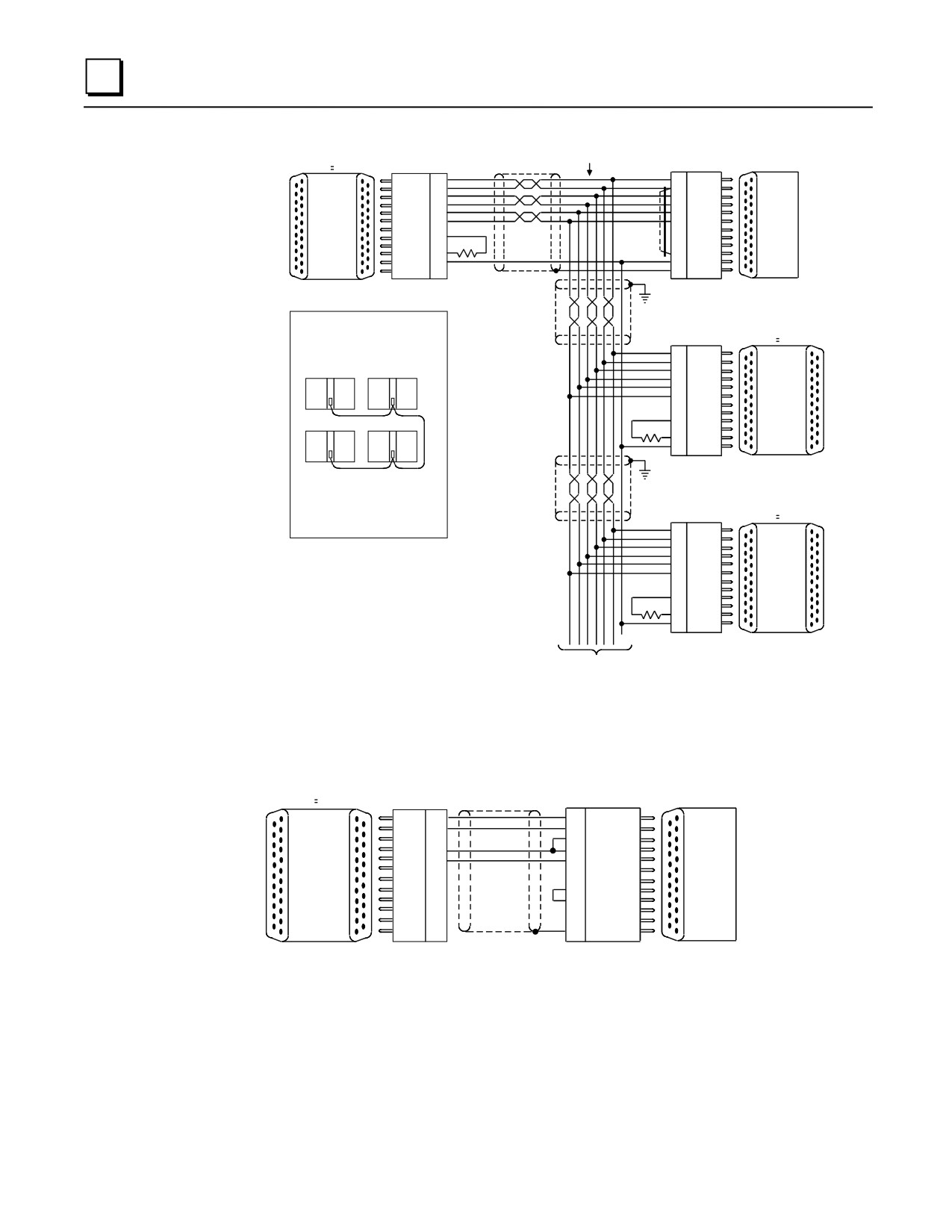
C
SHIELDED MAKE CONNECTIONS
a44932
TWISTED INSIDE D-CONNECTORS
J2
SW
J1
PAIRS
PIN
ON
PIN
SD (A)
16
13
RD (A')
SD (B)
17
25
RD (B')
RD (A')
15
9
SD (A)
RD (B')
14
21
SD (B)
SERIES 90
ISOLATED
CTS (A')
11
10
RTS (A)
CMM
CTS (B')
10
22
RTS (B)
PORT
REPEATER/
TERM
22
24
TERM
I
CONVERTER
TERM
23
GND
(BRICK)
7
OR
GND
7
1
SHLD
2
**
25- PIN
25- PIN
25- PIN
25- PIN
FEMALE
MALE
MALE
FEMALE
NOTE
WHEN WIRING RS-422 /485 MULTIDROP CABLES,
REFLECTIONS ON THE TRANSMISSION
J1
SW
J2
LINE CAN BE REDUCED BY CONFIGURING THE
PIN
CTS
CABLE IN A DAISY CHAIN FASHION AS
SHOWN BELOW.
15
RD (A')
14
RD (B')
16
SD (A)
MASTER
CMM SLAVE 1
17
SD (B)
ISOLATED
13
RTS (A)
REPEATER/
12
RTS (B)
CONVERTER
22
TERM
(BRICK)
23
TERM
(USED AS A
7
GND
CONVERTER)
CPU BUILT-IN PORT CMM SLAVE 2
150 OHMS
25- PIN
25- PIN
MALE
FEMALE
ALSO IT IS RECOMMENDED TO MAKE ANY
NECESSARY CONNECTIONS INSIDE THE
CABLE CONNECTOR TO BE MOUNTED ON
THE CMM. IT IS NOT RECOMMENDED TO
USE TERMINAL STRIPS OR OTHER TYPES
OF CONNECTORS ALONG THE LENGTH OF
SW ON
THE TRANSMISSION LINE.
PIN
J2
J1
16
RD (A')
17
RD (B')
15
SD (A)
14
SD (B)
ISOLATED
11
RTS (A)
REPEATER/
10
RTS (B)
CONVERTER
19
TERM
(BRICK)
18
TERM
(USED AS A
7
GND
REPEATER)
* 150 OHMS
25- PIN
25- PIN
MALE
FEMALE
TO OTHER DEVICES
(MAXIMUM OF 8 DEVICES ON A MULTIDROP)
TERMINATE THE RD (B') SIGNAL ONLY AT END OF MULTIDROP CABLE
TERMINATE CONNECTION ON FIRST AND LAST DROPS ONLY: ON THE CMM, INSTALL JUMPER TO CONNECT INTERNAL
120 OHM RESISTOR. ON THE ISOLATED REPEATER/CONVERTER, INSTALL 150 OHM RESISTOR (SUPPLIED)
ON THE CMM311, ONLY PORT 2 CAN SUPPORT RS-422/RS-485.
Figure C-9. Cable D; RS-422 Twisted Pair
J1
J2
SW CTS
PIN
PIN
a45239
SD
2
3
RD
RD
3
2
SD
CTS
5
5
CTS
GND
7
4
RTS
SERIES 90
7
GND
CMM
ISOLATED
8
DCD
PORT
REPEATER/
20
1
DTR
OR
CONVERTER
1
SHLD
(BRICK)
2
25- PIN
25- PIN
25- PIN
25- PIN
FEMALE
MALE
MALE
FEMALE
Figure C-10. Cable E; RS-232 Converter to CMM
C-10
Series 90-30 PLC Installation and Hardware Manual - August 2002
GFK-0356Q
Appendix
IC690ACC901 Miniconverter Kit
D
Description of Miniconverter
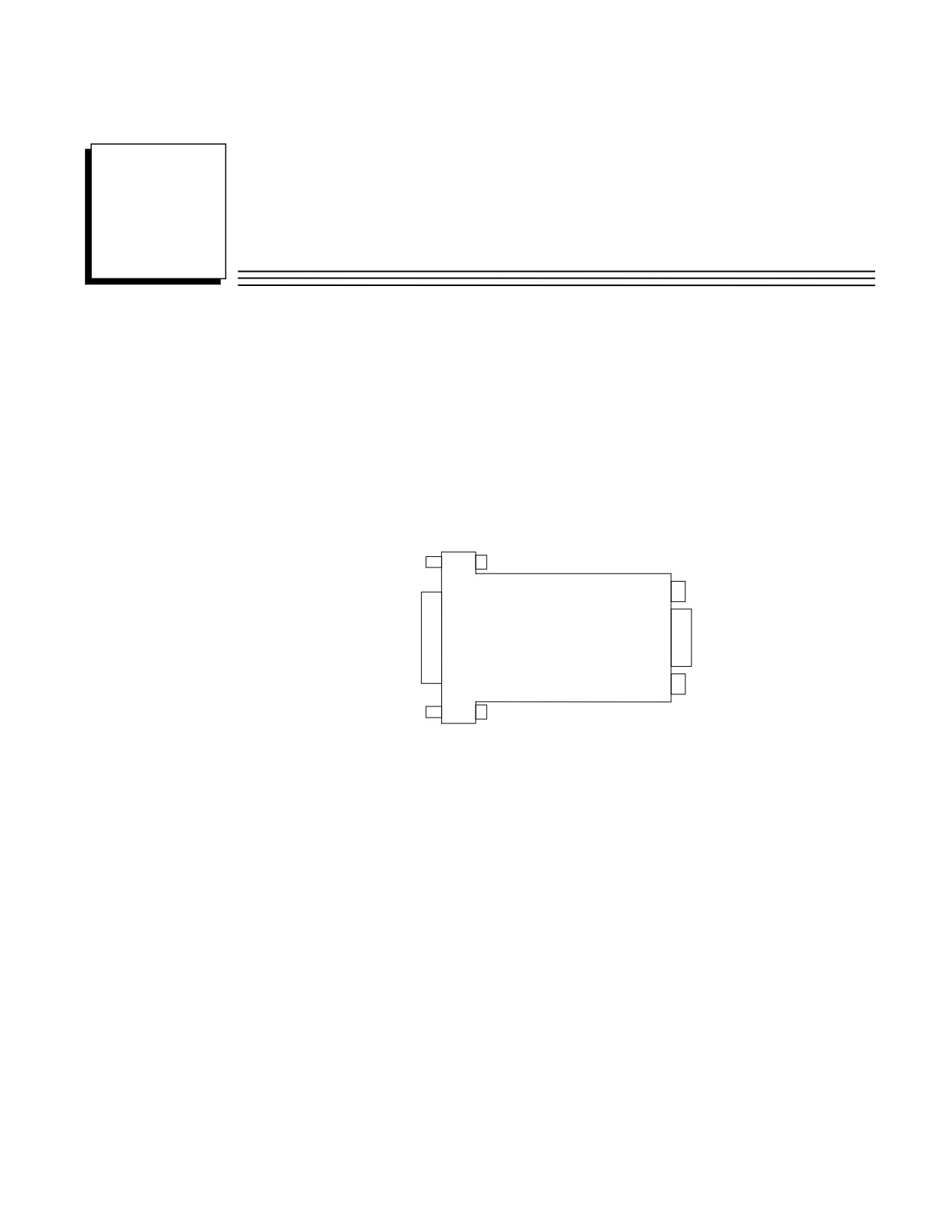
The Miniconverter Kit (IC690ACC901) consists of an RS-422 (SNP) to RS-232 Miniconverter, a 6
foot (2 meter) serial extension cable, and a 9-pin to 25-pin Converter Plug assembly. The 15-pin
SNP port connector on the Miniconverter plugs directly into the serial port connector on the Series
90-30 power supply, Series 90-70 CPU or Series 90-20 CPU. The 9-pin RS-232 port connector on
the Miniconverter connects to an RS-232 compatible device.
a44985
RS-422
RS-232
PORT
PORT
Figure D-1. Series 90 SNP to RS-232 Miniconverter
When used with an IBM PC-AT, or compatible computer, one end of the extension cable plugs into
the Miniconverter’s 9-pin serial port connector, the other end plugs into the 9-pin serial port of the
computer. The Converter plug (supplied with kit) is required to convert the 9-pin serial port
connector on the Miniconverter to the 25-pin serial port connector on the GE Fanuc Workmaster II
computer, or an IBM PC-XT or PS/2 Personal Computer.
The GE Fanuc Workmaster computer requires an additional adapter (not supplied with kit - please
contact your local GE Fanuc PLC distributor) for use with the Miniconverter.
GFK-0356Q
D-1

D
Pin Assignments
The pinouts of the Miniconverter are shown in the following two tables. The first table shows the
pinout for the RS-232 port, the second table shows the RS-422 port.
Pin Assignments, RS-232 Port
Table D-1 is for the RS-232 port. The direction of signal flow is with respect to the Miniconverter.
Table D-1. Miniconverter RS-232 Port
Pin
Signal Name
Direction
2
SD - Send Data
Output
3
RD - Receive Data
Input
5
GND - Ground
n/a
7
CTS - Clear To Send
Input
8
RTS - Request To Send
Output
The pinouts were chosen to allow direct connection (using a straight through, or 1 to 1 cable (as
provided with kit)) to the IBM PC-AT. Most IBM compatible computers equipped with an RS-232
port will provide a pinout compatible with the one shown above.
Pin Assignments, RS-422 Port
Table D-2 is the pinout for the Miniconverter’s RS-422 serial port. The direction of signal flow is
also with respect to the Miniconverter.
Table D-2. Miniconverter RS-422 Port
Pin
Signal Name
Direction
1
SHLD - Shield
n/a
5
+5 VDC - Power
Input
6
CTS(A’) - Clear To Send
Input
7
GND - Ground
n/a
8
RTS(B) - Request To Send
Output
9
RT - Receive Termination
Output
10
SD(A) - Send Data
Output
11
SD(B) - Send Data
Output
12
RD(A’) - Receive Data
Input
13
RD(B’) - Receive Data
Input
14
CTS(B’) Clear To Send
Input
15
RTS(A) - Request To Send
Output
D-2
Series 90-30 PLC Installation and Hardware Manual - August 2002
GFK-0356Q
D
System Configurations
The Miniconverter can be used in a point-to-point configuration as described above, or in a
multidrop configuration with the host device configured as the master and one or more PLCs
configured as slaves.
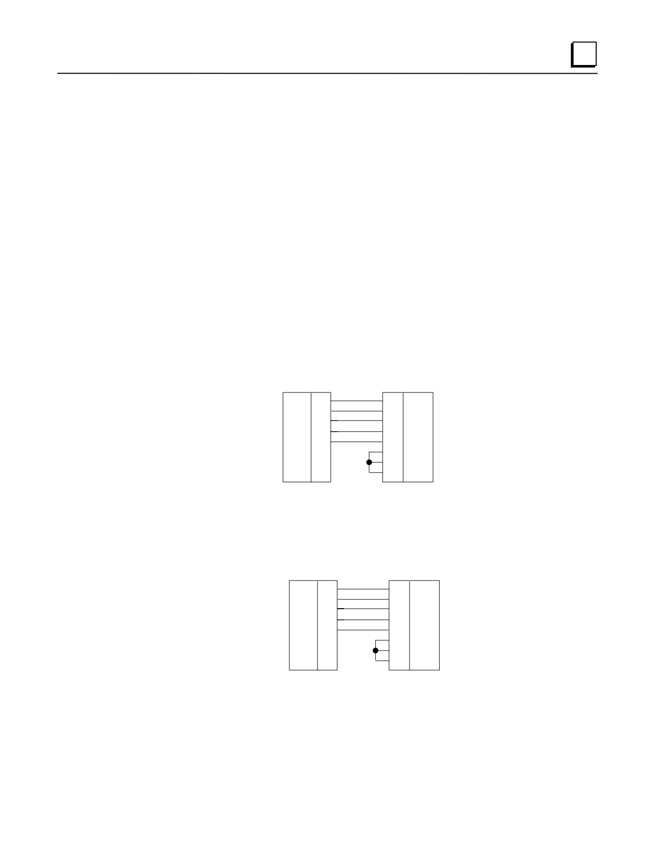
The multidrop configuration requires a straight through (1 to 1) cable from the Miniconverter’s RS-
422 port to the first slave PLC’s SNP port. Other slaves will require a daisy chain connection
between slaves. A maximum of eight devices can be connected in an RS-422 multidrop
configuration. All of the devices must have a common ground. If ground isolation is required, you
can use the GE Fanuc Isolated Repeater/Converter (IC655CCM590) in place of the Miniconverter.
When using the Miniconverter with a modem connection, it may be necessary to jumper RTS to
CTS (consult the user’s manual for your modem).
Cable Diagrams (Point-To-Point)
When connecting the Miniconverter to IBM PC and compatible computers with hardware
handshaking, the following cable connections should be used.
a44982
PIN
PIN
TXD
2
2
RXD
RXD
3
3
TXD
CTS
7
7
RTS
RTS
8
8
CTS
GND
5
5
GND
1
DCD
6
DSR
4
DTR
MINICONVERTER
IBM PC-AT
RS-232 PORT
9-PIN
9-PIN
CONNECTOR
CONNECTOR
Figure D-2. Miniconverter to PC-AT
a44983
PIN
PIN
TXD
2
3
RXD
RXD
3
2
TXD
CTS
7
4
RTS
RTS
8
5
CTS
GND
5
7
GND
8
DCD
6
DSR
20
DTR
MINICONVERTER
WORKMASTER II,
RS-232 PORT
IBM PC-XT, PS/2
9-PIN
25-PIN
CONNECTOR
CONNECTOR
Figure D-3. Miniconverter to Workmaster II, PC-XT, PS/2
GFK-0356Q
Appendix D IC690ACC901 Miniconverter Kit
D-3

D
a44984
PIN
PIN
TXD
2
3
RXD
RXD
3
2
TXD
CTS
7
4
RTS
RTS
8
5
CTS
GND
5
7
GND
MINICONVERTER
WORKMASTER
RS-232 PORT
9-PIN
9-PIN
CONNECTOR
CONNECTOR
Note: Additional adapter required
Figure D-4. Miniconverter to 9-Pin Workmaster or PC-XT Computer
Table D-3. Miniconverter Specifications
Mechanical:
RS-422
15-pin D shell male for direct mounting to Series 90 serial port.
RS-232
9-pin D shell male for connection to RS-232 serial port of a Workmaster
II computer or Personal Computer.
Electrical and General:
Voltage Supply
+5 VDC (supplied by PLC power supply)
Typical Current
Version A (IC690ACC901A) - 150 mA
Version B (IC690ACC901B) - 100 mA
Operating Temperature
0 to 70°C (32 to 158°F)
Baud Rate
38.4K Baud maximum
Conformance
EIA-422 (Balanced Line) or EIA-423 (Unbalanced Line)
Ground Isolation
Not provided
D-4
Series 90-30 PLC Installation and Hardware Manual - August 2002
GFK-0356Q
Appendix
IC690ACC903 Port Isolator
E
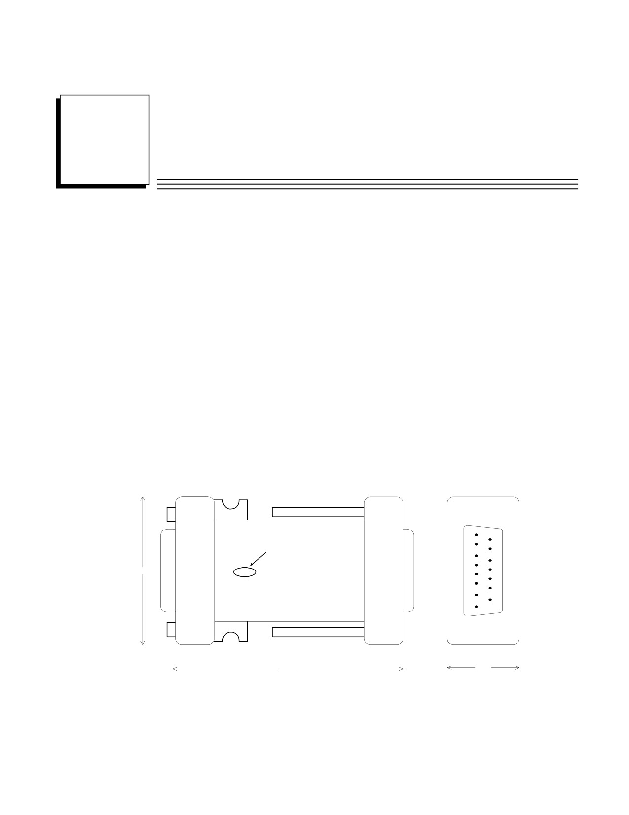
The IC690ACC903 RS-485 Port Isolator replaces the IC655CMM590 Isolated Repeater/Converter
(also referred to as the “Brick”). The device features 500 volts of isolation in a compact package
servicing all IC693, IC697, and IC200 PLC product lines. The product connects directly to an RS-
485 serial port or though a short extender cable provided with the device. The extension cable is
intended for use in applications where direct connection to the port is obstructed by surrounding
equipment or when it is not acceptable for the device to protrude from a PLC module. The Port
Isolator can operate in either single- or multi-drop mode, which is selected by a slide switch on the
top of the module.
The Port Isolator provides the following features:
• Four opto-isolated signal channels: SD, RD, RTS, and CTS
• Electrical compatibility with RS-485
• Single- or multi-drop operation
• Input termination consistent with standard for serial channels
• A 5V DC/DC converter for power isolation
• Hot insertion is supported
FRONT VIEW
Multidrop
Switch
1.7 in
TOP VIEW
FRONT VIEW
2.6 in
0.7 in
Figure E-1. RS485 Port Isolator
GFK-0356Q
E-1

E
Connectors
The Isolator provides two connectors, one 15 pin male D-type (PL1) and one
15 pin female D-type (PL2).
RS-485 Connectors
Pin
Pin Name
Pin Type
Description
PL1
1
SHLD
-
Chassis Ground
2
NC
-
3
NC
-
4
NC
-
5
5V
-
+5V power
6
CTS (A')
In
Clear to send -
7
0V
-
Signal Ground
8
RTS (B)
Out
Request to send +
9
NC
-
10
SD (A)
Out
Send data -
11
SD (B)
Out
Send data +
12
RD (A')
In
Read data -
13
RD (B')
In
Read data +
14
CTS (B')
In
Clear to send +
15
RTS (A)
Out
Request to send -
Pin
Pin Name
Pin Type
Description
PL2
1
NC
-
2
NC
-
3
NC
-
4
NC
-
5
5V
-
+5V power
6
RTS (A)
Out
Request to send -
7
0V
-
Signal Ground
8
CTS (B')
In
Clear to send +
9
RT
-
Terminating Resistor*
10
RD (A')
In
Read data -
11
RD (B')
In
Read data +
12
SD (A)
Out
Send data -
13
SD (B)
Out
Send data +
14
RTS (B)
Out
Request to send +
15
CTS (A')
In
Clear to send -
* Use the terminating resistor if the Port Isolator is used in port-to-port mode or at the end of a multi-drop
configuration. To terminate the RD balanced line, place a jumper wire from pin 9 to pin 10.
* A denotes - and B denotes +. A and B denote outputs and A' and B' denote inputs.
E-2
Series 90-30 PLC Installation and Hardware Manual - August 2002
GFK-0356Q
E
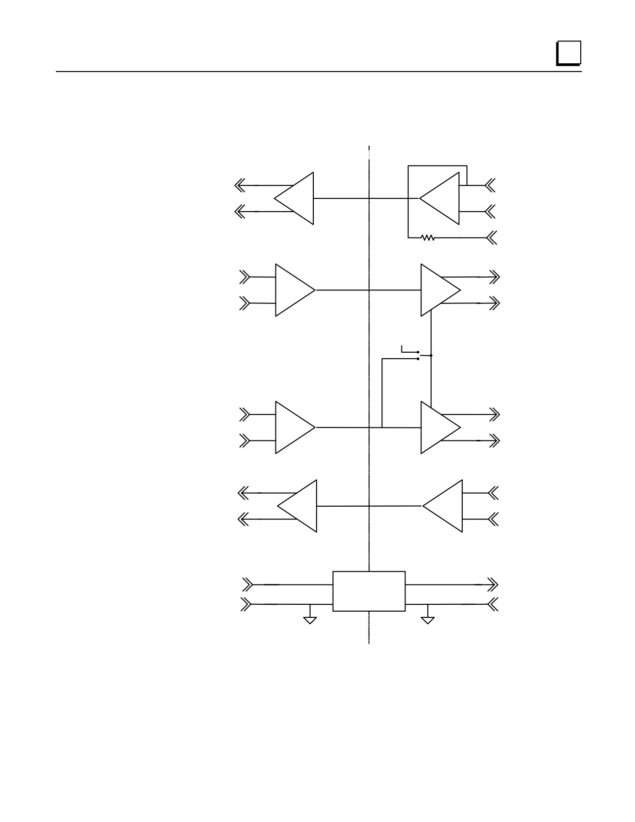
Logic Diagram
Optical Isolation
15-pin male D-connector
15-pin female D-connector
PL1
PL2
11
11
SD(B)
RD(B')
10
10
SD(A)
RD(A')
9
RT
121 ohms
13
13
RD(B')
SD(B)
12
12
RD(A')
SD(A)
Output Enable
Always on
(single port mode)
+5V
Multidrop
Switch
RTS Driven
(multidrop mode)
Output Enable
14
14
CTS(B')
RTS(B)
6
6
CTS(A')
RTS(A)
8
8
RTS(B)
CTS(B')
15
15
RTS(A)
CTS(A')
+5Vdc
DC/DC
+5Vdc
Converter
GND
GND
Ground 1
Ground 2
Figure E-2. IC690ACC903 Block Diagram
GFK-0356Q
Appendix E IC690ACC903 Port Isolator
E-3
E
Installation
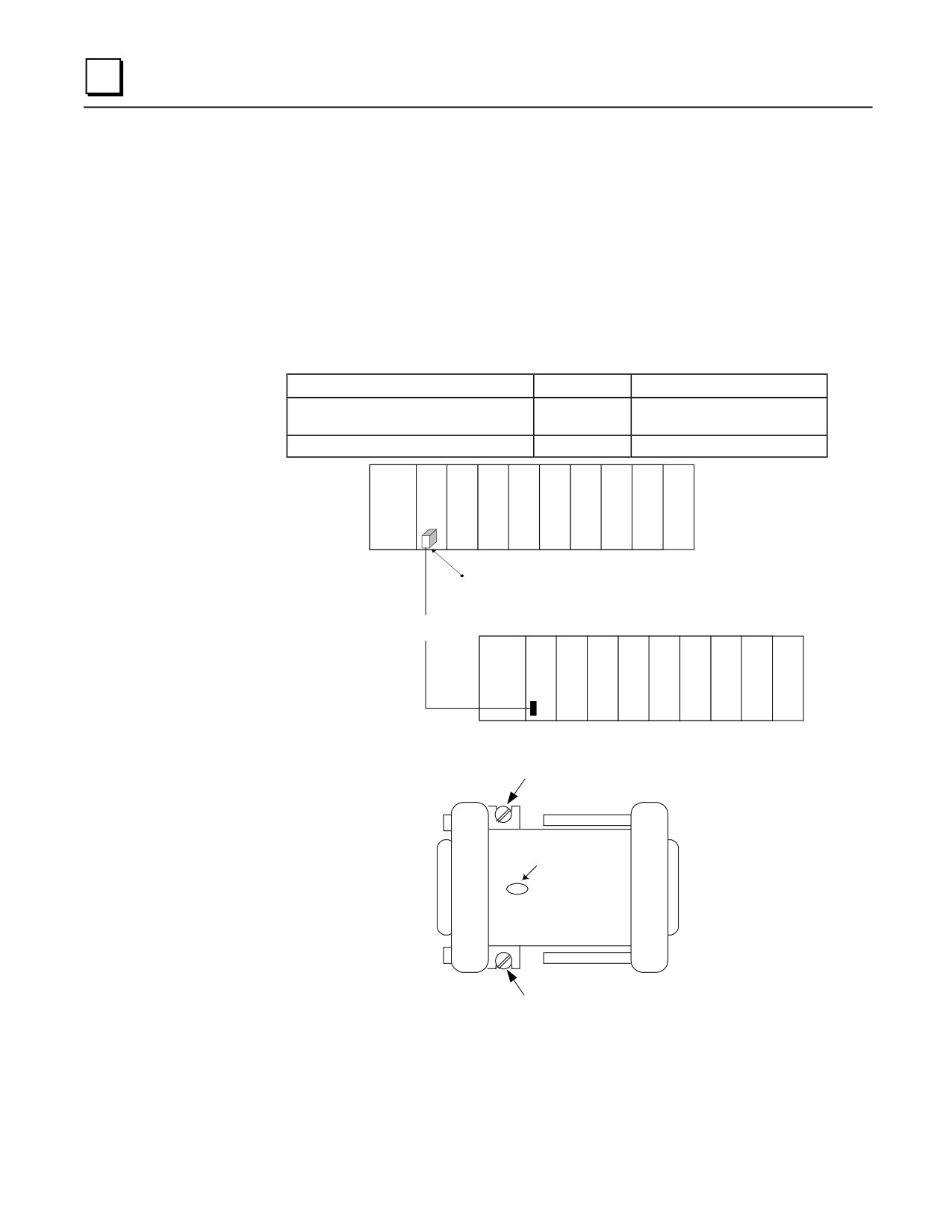
The Isolator is packaged in a contoured plastic enclosure designed for either direct attachment to a
serial port or through a 12” extender cable for panel mounted applications. Two M3 thumbscrews
secure the device to its mating connector. The device can be easily inserted into an existing
communication channel with no additional hardware. In Figure E-2, the Isolator is shown
connected directly to a CPU module. Alternatively, the Isolator can be mounted separately from the
PLC system using the extender cable provided. For mounting separately to a panel, you will need
to provide two #6-32 (4 mm)mounting screws (Figure E-3).
When installing the Isolator, tighten the connector screws and panel mounting screws (if used) to
the following torque values:
Screws
Type
Torque
Connector Thumbscrews (supplied with
M3
8 in./lbs. (0.9 Newton-meter)
Isolator)
Panel Mounting Screws (user-supplied)
#6/32 (4 mm)
12 in./lbs. (1.4 Newton-meters)
PLC 1
PS
CPU
RS-485 Port
Isolator
4000 ft
SNP
Cable
PLC 2
PS
CPU
Figure E-3. RS-485 Port Isolator in PLC Network
#6-32 (4 mm) screw
Multidrop Switch
TOP
VIEW
#6-32 (4 mm) screw
Figure E-4. Mounting Port Isolator to Panel
E-4
Series 90-30 PLC Installation and Hardware Manual - August 2002
GFK-0356Q
E
The RS485 Port Isolator supports both port-to-port and multi-drop configurations (Figure E-4). For
installation information, refer to section 3 of the Serial Communications User's Manual
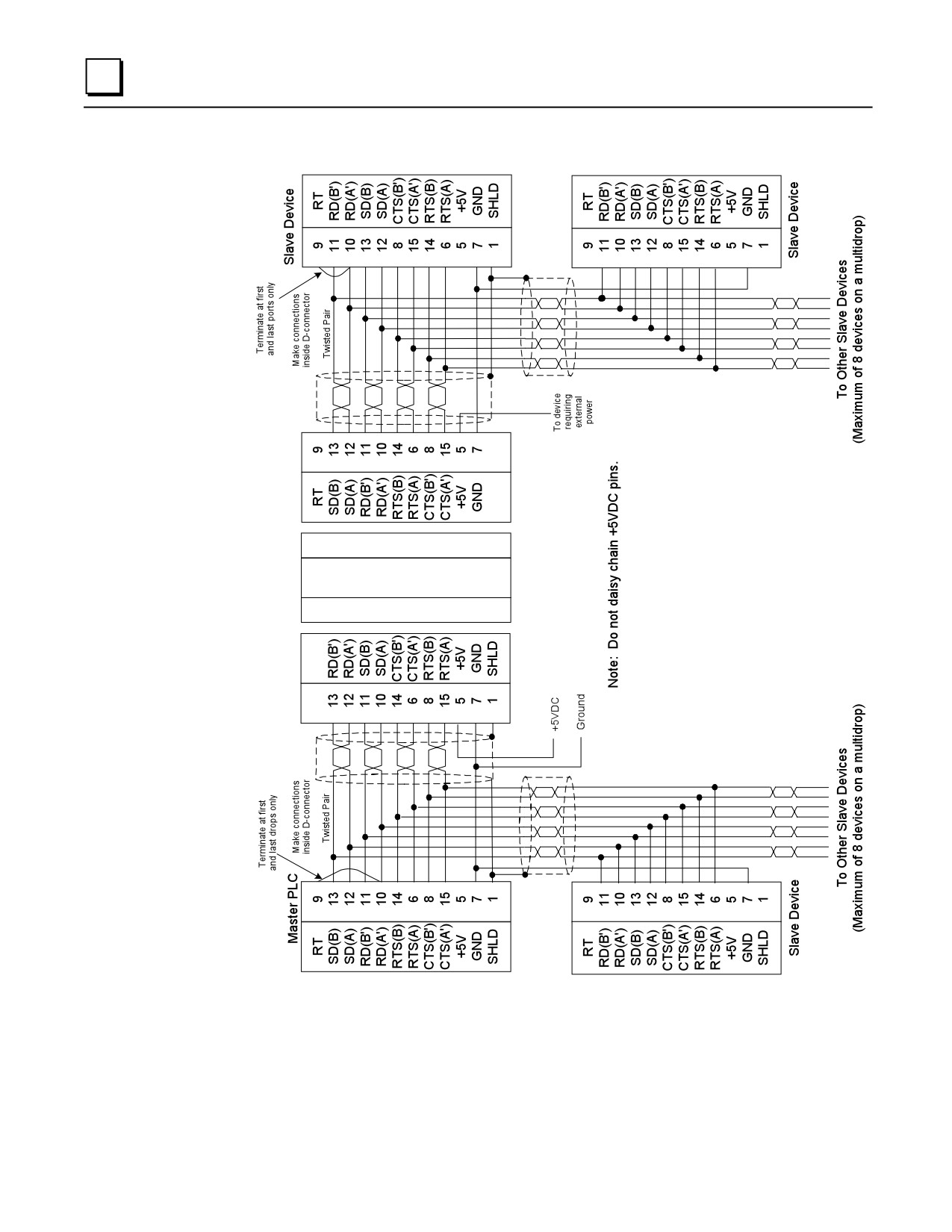
(GFK-0582). One configuration not covered in the User's Manual is the case where the Isolator is
powered by a source other than the host port. This configuration is used to prevent an interrupt in
communications if the host system requires a power cycle. It also prevents power loss to equipment
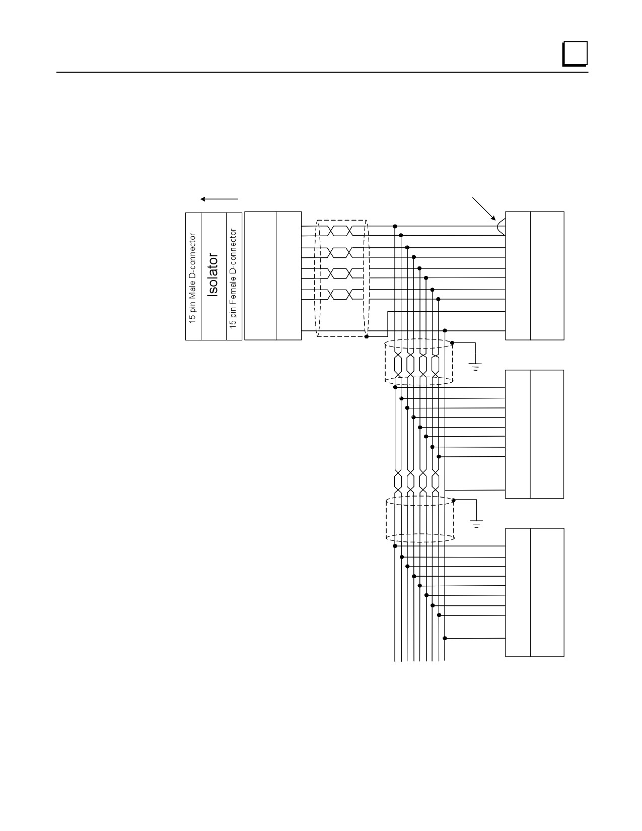
using the port for power. For this, you will need to build a custom cable as shown in Figure E-5.
Terminate at first
and last drop only
Slave Device
Master PLC
15 pin port
Make connectons
Twisted Pairs
RT
9
inside D connectors
9
RT
SD(B)
13
11
RD(B')
SD(A)
12
10
RD(A')
RD(B')
11
13
SD(B)
RD(A')
10
12
SD(A)
RTS(B)
14
8
CTS(B')
RTS(A)
6
15
CTS(A')
CTS(B')
8
14
RTS(B)
CTS(A')
15
6
RTS(A)
1
SHLD
+5V
5
5
+5V
GND
7
7
GND
Slave Device
15 pin port
9
RT
11
RD(B')
10
RD(A')
13
SD(B)
12
SD(A)
8
CTS(B')
15
CTS(A')
14
RTS(B)
6
RTS(A)
1
SHLD
5
+5V
7
GND
Slave Device
25 pin port
24
RT
25
RD(B')
13
RD(A')
21
SD(B)
9
SD(A)
23
CTS(B')
11
CTS(A')
22
RTS(B)
10
RTS(A)
7
GND
1
SHLD
To Other Slave Devices
(Maximum of 8 devices on a multidrop)
Figure E-5. Multidrop Configuration Connecting Devices with 15-Pin Ports and 25-Pin Ports
GFK-0356Q
Appendix E IC690ACC903 Port Isolator
E-5
E
Figure E-6. Cable for Supplying External Power Through the Port Isolator
E-6
Series 90-30 PLC Installation and Hardware Manual - August 2002
GFK-0356Q

E
Specifications
Mechanical
RS-485
15-pin D shell male for direct mounting to serial port on the programmable
controller
15-pin D shell female for communication cable
Installation Hardware
Two M3 thread connector thumbscrews. Recommended torque: 8 in./lbs. (0.9
Newton-meter). These are supplied with Isolator.
Two user supplied #6/32 (4mm) thread panel mounting screws. Recommended
torque: 12 in./lbs. (1.4 Newton-meter)
Electrical
Voltage Supply
+5VDC (supplied by port)
Typical Current
25 mA
100 mA available for external equipment
Ground Isolation
500 Volts
Conformance
EIA-422/485 Balanced Line
Operating
0° - 60°C (32° - 140° F)
Temperature
Baud Rate
Those supported by PLC
Note: This appendix is based on Data Sheet GFK-1663.
GFK-0356Q
Appendix E IC690ACC903 Port Isolator
E-7
Appendix
Calculating Series 90-30 Heat Dissipation
F
Overview
Series 90-30 PLCs must be mounted in a protective enclosure. The enclosure should be capable of
properly dissipating the heat produced by all of the devices mounted inside it. This appendix
describes how to calculate heat dissipation for a Series 90-30 PLC. The strategy is to calculate a
heat dissipation value, in watts, for each individual module in the PLC. To obtain a total heat
dissipation figure for the PLC, add the individual values together.
The procedure consists of the following steps:
Step 1: Basic Method to Calculate Module Dissipation
F-2
Step 2: Calculation for PLC Power Supplies
F-3
Step 3: Output Calculations for Discrete Output Modules
F-3
Step 4: Input Calculations for Discrete Input Modules
F-4
Step 5: Final Calculation
F-6
Information Required
■ In addition to the information in this manual, you will need GFK-0898, Series 90-30 I/O
Module Specifications Manual.
■ You will need operating current values for the discrete output devices connected to the PLC’s
discrete output modules. These include control relays, motor starters, solenoids, pilot lights,
etc. Each device manufacturer publishes these values. If an exact value is not available for a
device, you can make a close estimate by obtaining the value for a similar device from a
catalog. These values are also needed for selecting Output modules during the design process
in order to ensure that the modules’ maximum ratings are not exceeded.
GFK-0356Q
F-1
F
Procedure
Step 1: Basic Method to Calculate Module Dissipation
Note that this step does not apply to Power Supply Modules, which are covered in Step 2. The
values needed for this calculation are found in the “Load Requirements” table in Chapter 12.
Use the following electrical power formula in these calculations
Power (in watts) = Voltage (in volts) x Current (in Amps).
Assume that all input power to these modules is eventually dissipated as heat. The procedure is:
■ Look up the module in the “Load Requirements for Hardware Components” table (Chapter 12)
and obtain the current values for each of the three power supply voltages listed. The voltage is
printed at the head of each column. All modules use the 5VDC supply, and a relatively few
modules also use one or both of the two 24VDC supplies.
■ For a given module, calculate the power dissipation for each column in the table that contains a
current value by multiplying the current value (in Amps) times the voltage for that column. For
modules using more than one voltage, add the calculated power values to arrive at the total for
the module.
Example 1:
The “Load Requirements” table shows that the IC693CPU352 module draws:
■
910 mA from the +5VDC supply.
■ No current from either of the two 12VDC supplies
To calculate power dissipation, multiply 0.910 Amps times 5 volts. The answer is:
■
4.55 watts (of heat dissipated by this module)
Example 2:
The “Load Requirements” table shows that the IC693MDL241 module draws:
■
80 mA from the +5VDC supply
■
125 mA from the +24VDC Isolated supply
To calculate power dissipation from the +5VDC supply:
Multiply 0.08 Amps times 5 volts to arrive at a value of 0.40 watts.
To calculate power dissipation from the +24VDC supply:
Multiply 0.125 Amps times 24 volts to arrive at a value of 3.0 watts.
Adding the two together yields a total heat dissipation by this module of 3.4 watts.
F-2
Series 90-30 PLC Installation and Hardware Manual - August 2002
GFK-0356Q
F
Step 2: Calculation for PLC Power Supplies
A basic rule for Series 90 power supplies is that they are 66% efficient. Another way of stating this
is that the power supply dissipates 1 watt of power in the form of heat for every 2 watts of power it
delivers to the PLC. Therefore, you can calculate the total power requirement for all of the
modules in the rack served by a particular power supply using the method in Step 1 above, then
divide that figure by 2 to arrive at the power supply dissipation value. You cannot simply use the
rating of the power supply (such as 30 watts) for this calculation because the application may not
require the full capacity of the power supply. If you are using the +24VDC output on the power
supply’s terminal strip, you should calculate the power drawn, divide the value by 2, and add it to
the total for the power supply. Since each Series 90-30 rack has its own power supply, each rack
should be calculated on an individual basis.
Step 3: Output Calculations for Discrete Output Modules
Discrete solid state Output modules require two calculations, one for the module’s signal-level
circuits, which was already done in Step 1, and one for the output circuits. (This output circuit
calculation is not required for the Relay Output modules.) Since the solid state output switching
devices in these modules will drop a measurable amount of voltage, their power dissipation can be
calculated. Note that the power dissipated by the output circuits comes from a separate power
source, so it is not included in the figure used to calculate PLC power supply dissipation in Step 2.
To calculate output circuit power dissipation:
■ In the Series 90-30 I/O Module Specifications Manual, GFK-0898, find the value for the
Output Voltage Drop for your particular module.
■ Obtain the required current value for each device (such as a relay, pilot light, solenoid,
etc.) connected to an output point on the module and estimate its percent of “on-time.” To
obtain the current values, check the device manufacturer’s documentation or an
electronics catalog. The percent of on-time can be estimated by someone familiar with
how the equipment operates or will operate.
■ Multiply the Output Voltage Drop times the current value times the estimated percent of
on-time to arrive at average power dissipation for that output.
■ Repeat for all outputs on the module. To save time, you could determine if several
outputs were similar in current draw and on-time so that you would only have to make
their calculation once.
■ Repeat these calculations for all Discrete Output modules in the rack.
Discrete Output Module Example:
The Series 90-30 PLC I/O Module Specifications Manual, GFK-0898, lists the following for the
IC693MDL340 16-Point Discrete 120VAC Output Module:
Output Voltage Drop:
1.5 Volts maximum
Use that value for all of the calculations for this module.
In this example, two of the Output module’s output points drive solenoids that control the advance
and retract travel of a hydraulic cylinder. The solenoid manufacturer’s data sheet shows that each
GFK-0356Q
Appendix F Calculating Series 90-30 Heat Dissipation
F-3
F
solenoid draws 1.0 Amp. The cylinder advances and retracts once every 60 seconds that the
machine is cycling. It takes 6 seconds to advance and 6 seconds to retract.
Since the cylinder takes equal time to advance and retract, both solenoids are on for equal lengths
of time: 6 seconds out of every 60 seconds, which is 10% of the time. Therefore, since both
solenoids have equal current draws and on-times, our single calculation can be applied to both
outputs.
Use the formula Average Power Dissipation = Voltage Drop x Current Draw (in Amps) x Percent
(expressed as a decimal) of on-time:
1.5
x 1.0 x 0.10 = 0.15 watts per solenoid
Then multiply this result by 2 since we have two identical solenoids:
0.15 watts x 2 Solenoids = 0.30 watts total for the two solenoids
Also in this example, the other 14 output points on this 16-point module operate pilot lights on an
operator’s panel. Each pilot light requires .05 Amps of current. Seven of the pilot lights are on
100% of the time and seven are on an estimated 40%.
For the 7 lights that are on 100% of the time:
1.5 x .05 x 1.00 = 0.075 watts per light
Then multiply this value by 7:
0.075 watts x 7 lights = 0.525watts total dissipation for the first 7 lights
For the 7 lights that are on 40% of the time:
1.5 x .05 x 0.40 = .03 watts per light
Then multiply this value by 7:
0.03 watts x 7 lights = 0.21 watts total dissipation for the other 7 lights
Adding up the individual calculations, we get:
0.30 + 0.525 + 0.21 = 1.035 watts for the module’s total output calculation
Step 4: Input Calculations for Discrete Input Modules
A Discrete Input Module requires two calculations, one for the module’s signal-level circuits,
which was already done in Step 1, and one for the input circuits. Note that the power dissipated by
the input circuits comes from a separate power source, so are not included in the figure used to
calculate PLC power supply dissipation in Step 2. We will assume that all input circuit power
delivered to these modules is eventually dissipated as heat. The procedure is:
■ Find the value for the Input Current in the “Specifications” table for your input module in
the Series 90-30 I/O Module Specifications Manual, GFK-0898.
■ Multiply the input voltage times the current value times the estimated percent of on-time
to arrive at average power dissipation for that input.
F-4
Series 90-30 PLC Installation and Hardware Manual - August 2002
GFK-0356Q
F
■ Repeat for all inputs on the module. To save time, you could determine if several inputs
were similar in current draw and on-time so that you would only have to make their
calculation once.
■ Repeat these calculations for all Discrete Input modules in the rack.
Discrete Input Module Example:
The “Specifications” table for the IC693MDL240 16-Point Discrete 120 VAC Input Module in the
Series 90-30 PLC I/O Module Specification Manual, GFK-0898, gives the following information:
Input Current:
12 mA (typical) at rated voltage
Use this value for all of the input calculations for this module.
In this example, eight of the Input Module’s points are used for switches that, for normal operation,
stay on (closed) 100% of the time. These include the Emergency Stop, Over Temperature, Lube
Pressure OK, and similar switches.
Use the formula Average Power Dissipation = Input Voltage x Input Current (in Amps) x Percent
(expressed as a decimal) of on-time:
120 x .012 x 1.0 = 1.44 watts per input
Then multiply this result by 8:
1.44 watts x 8 inputs = 11.52 watts total for the 8 inputs
Also in this example, two input points on this 16-point module are for the Control On and Pump
Start pushbuttons. Under normal conditions, these pushbuttons are only pressed once per day for
about one second - just long enough to start up the control and pump. Therefore, their effect on
our power calculation is negligible and we will assume a power dissipation of zero for them:
0.0 watts total for 2 inputs
For the remaining six inputs of our sixteen point module, it is estimated that they will be on for an
average of 20% of the time. So the following calculation is made for these six inputs:
Using the formula of Average Power Dissipation = Input Voltage x Input Current (in Amps) x
Percent (expressed as a decimal) of on-time:
120 x .012 x 0.20 = 0.288 watts per input
Then multiply this result by 6:
0.288 watts x 6 inputs = 1.728 watts total for the 6 inputs
Finally, adding up the individual calculations, we get:
11.52 + 0.0 + 1.728 = 13.248 watts for the module’s total input calculation
GFK-0356Q
Appendix F Calculating Series 90-30 Heat Dissipation
F-5
F
Step 5: Final Calculation
Once the individual power dissipations have been calculated, add them all to obtain total PLC heat
dissipation. Note that the PLC baseplate, analog input modules, and analog output modules have
been ignored in this procedure because their power dissipation values are negligible when
compared with the total. Also, since each Series 90-30 rack has its own power supply, each rack
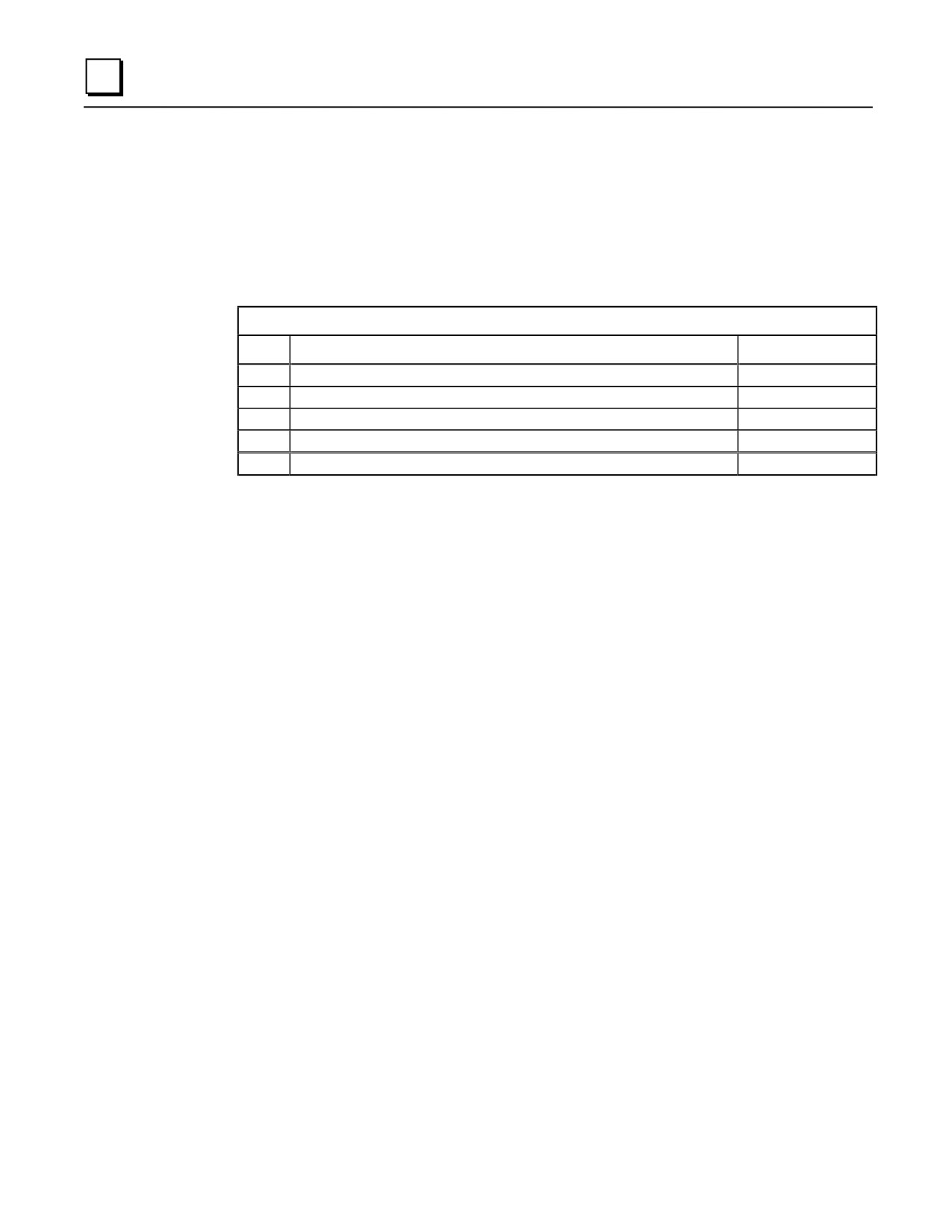
should be calculated on an individual basis. The following table summarizes the final calculation:
Series 90-30 Rack Heat Dissipation Calculation Summary
Step
Description
Value (Watts)
1
Calculate total of dissipation values for all modules in the rack
2
Divide value obtained in Step 1 by 2 to obtain Power Supply value
3
Calculate total of all Output modules’ output dissipation values
4
Calculate total of all Input modules’ input dissipation values
5
Add the above four values to obtain the total dissipation of the rack
Other Information Related to Enclosure Sizing
The “Baseplates” chapter of this manual contains rack dimensions and minimum ventilation
clearance distances required around the racks. The “Cables” chapter contains clearance dimensions
for cables that mount on the front of modules.
F-6
Series 90-30 PLC Installation and Hardware Manual - August 2002
GFK-0356Q
Appendix
Catalog Number to Publication Cross-Reference
G
Manuals are not shipped with many of the Series 90-30 products; they must be ordered separately.
This appendix can help you identify the correct documentation to order and use. Products are arranged
in this appendix by categories such as Analog I/O Modules, Baseplates, Communications Modules,
etc. The category headings are listed in alphabetical order. Modules that share common
documentation are grouped under a generic catalog number, such as IC693ALGxxx for the Analog I/O
modules.
Note that you may not need every publication listed for a particular product. Your need for some of
the publications depends on your application. For example, if you intend to use Logicmaster
programming software to configure and program your PLC, you will not need manuals for the other
programming software products or the Hand Held Programmer. Or, if you are going to program your
Programmable Coprocessor module using the C computer language, you will not need the MegaBasic
language manual. A list of publication titles is included at the end of this data sheet.
Abbreviations Used
HHP — Hand-Held Programmer
LM90 — Logicmaster, a DOS-based programming and configuration software
SFC — Sequential Function Chart
GFK-0356Q
G-1

G
General System Information
90-30 PLC System
Installation: GFK-0356
Installation for Conformance to Standards: GFK-1179
Configuration Options:
Configuration (HHP): GFK-0402
Configuration (LM90): GFK-0466
Configuration (Control): GFK-1295
Configuration (VersaPro): GFK-1670
Configuration (CIMPLICITY Machine Edition Logic Developer-
PLC: GFK-1868
Analog I/O Modules
Catalog Number
Task: Publication Number
All Analog Input, Output, and
Installation, Configuration, Specifications: GFK-0898
Combination. Modules
(IC693ALGxxx)
Baseplates
All Series 90-30 Baseplates
Installation: GFK-0356
(IC693CHSxxx)
Configuration Options:
Configuration (HHP): GFK-0402
Configuration (LM90): GFK-0466
Configuration (Control): GFK-1295
Configuration (VersaPro): GFK-1670
Configuration (CIMPLICITY Machine Edition Logic Developer-PLC:
GFK-1868
G-2
Series 90-30 PLC Installation and Hardware Manual - August 2002
GFK-0356Q