FANUC Series 0i-MODEL D, Series 0i Mate-MODEL D. CONNECTION MANUAL (HARDWARE) - page 16
B-64303EN/03
APPENDIX
G.ANALOG SERVO ADAPTER
G ANALOG SERVO ADAPTER
NOTE
Analog servo adapter is available only for retrofit purpose.
G.1 OVERVIEW
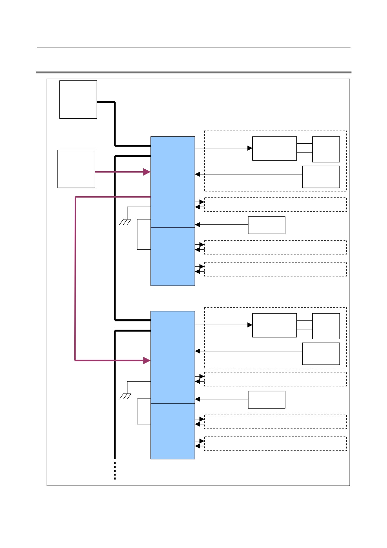
When a motor driven by analog servo amplifier is used, Analog servo adapter is required. Analog servo
adapter is connected through an optical fiber cable as a unit on FSSB line.
G.2 SPECIFICATIONS
• Two types of analog servo interface
-
Type F analog servo interface
The ready signal and alarm signal from servo amplifier are 5VDC signals.
-
Type M analog servo interface
The ready signal and alarm signal from servo amplifier are 24VDC signals.
• Analog servo adapter consists of basic unit and additional unit. The basic unit has two analog servo
axis interface and feedback interface. The additional unit has two analog servo axis interface and
feedback interface. Therefore, up to 4 analog servo can be connected to Analog servo adapter.
• The maximum number of interface units like Analog servo adapter or a separate detector interface
unit that can be connected to one FSSB line is two.
• Separate absolute pulse coder can be connected.
• A quad B or FANUC serial interface encoder can be connected.
• Environmental temperature of unit is
0˚C to 55 ˚C in operation,
-20˚C to 60˚C in store or
transportation.
G.3 ORDER SPECIFICATIONS
Item
Specification
Remarks
Analog servo adapter basic unit
A02B-0303-C180
Up to 2 axes
Analog servo adapter additional unit
A02B-0259-C181
Up to 2 axes
Flat cable
A02B-0259-K850
Spare fuse
A02B-0200-K103
24VDC
5.0A
- 437 -
G.ANALOG SERVO ADAPTER
APPENDIX
B-64303EN/03
G.4 CONNECTION DIAGRAM
CNC
FSSB line
Analog
Analog voltage
Analog
Servo
servo
servo amp.
motor
24VDC
adapter
Power
(basic)
Feedback
Pulse
encoder
GND
Battery
Analog
servo
adapter
Flat
unit
cable
(additional)
Power
Analog
Analog voltage
Analog
Servo
servo
servo amp.
motor
adapter
(basic)
Feedback
Pulse
encoder
GND
Battery
Analog
servo
adapter
Flat
(additional)
cable
- 438 -
B-64303EN/03
APPENDIX
G.ANALOG SERVO ADAPTER
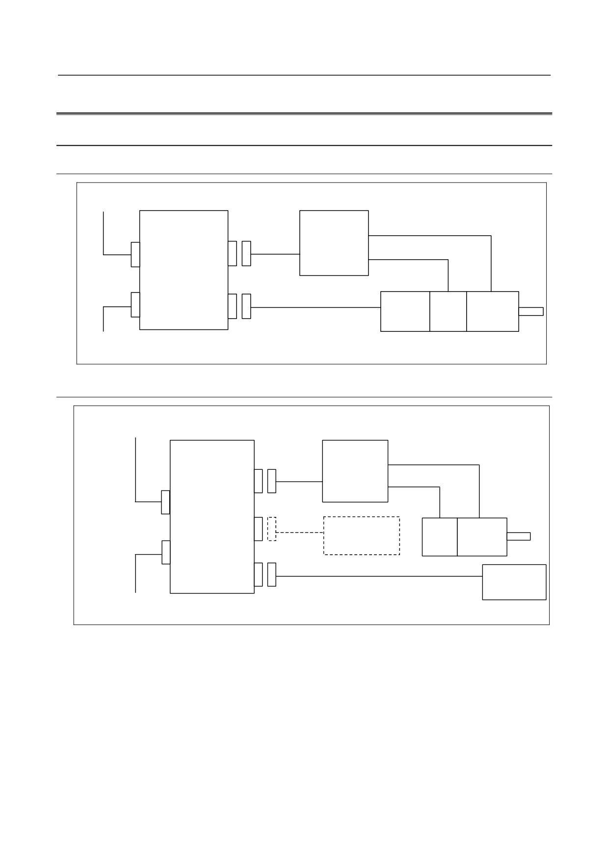
G.5 CONNECTION OF TYPE F ANALOG SERVO INTERFACE
G.5.1 System Structure
G.5.1.1 In case of using the built-in pulse coder
FSSB Upper step
Analog servo
Analog
adapter
servo
amplifier
J155
COP10B
JV1nL
J156A / J156B
Pulse
servo
COP10A
JF10nL
TG
encoder
motor
FSSB Lower step
G.5.1.2 In case of using the separate detector
FSSB Upper step
Analog servo
Analog
adapter
servo
amplifier
J155
JV1nL
COP10B
J37
JA4L
Battery
TG
servo
motor
COP10A
J156A / J156B
Separate
JF10nL
detector
FSSB Lower step
- 439 -
G.ANALOG SERVO ADAPTER
APPENDIX
B-64303EN/03
G.5.2 Detail of Connection
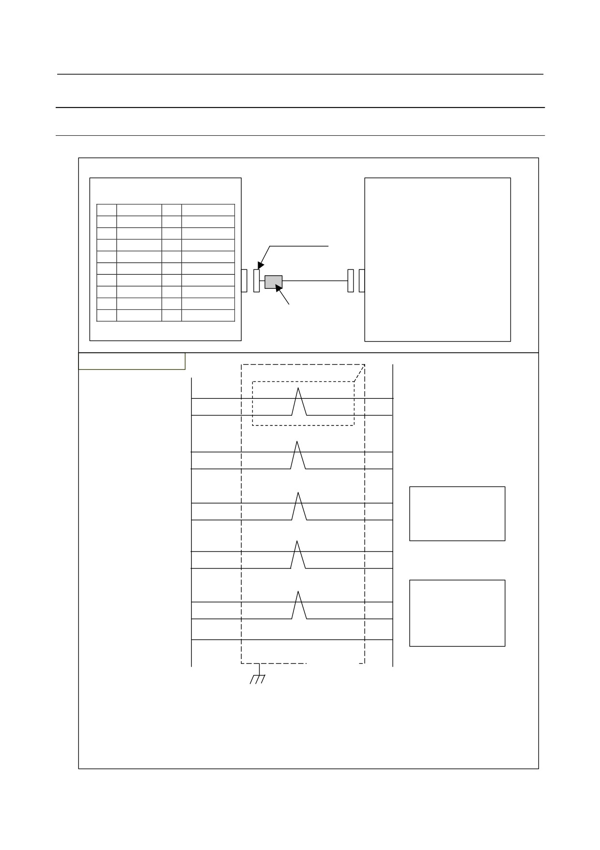
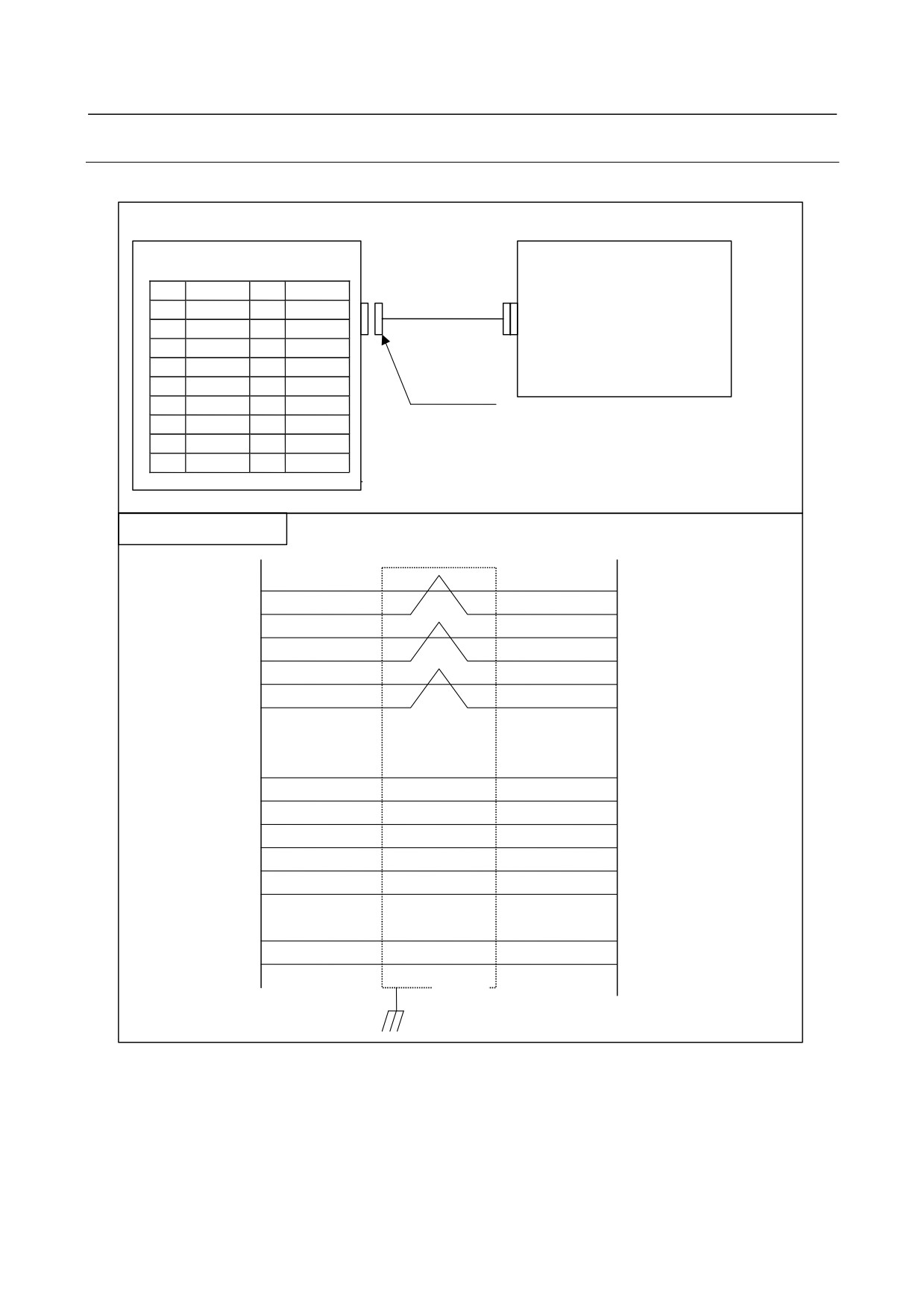
G.5.2.1 Cable J155
Cable J155 is for between Analog servo adapter (JV1nL) and analog servo amplifier.
Analog servo adapter
Analog servo amplifier
Connector
JV1nL
PCR-E20FS
(PCR-EV20MDT)
or
PCR-E20FA
1
(A)
11
(B)
Housing
2
(*A)
12
(*B)
PCR-V20LB
3
*ENBL
13
OVL
4
0V
14
0V
5
(Z)
15
(ALM)
6
EC
16
0V
J155
7
VCMD
17
(*SRDY)
8
0V
18
0V
9
(*Z)
19
(24VOUT)
Ferrite core
10
*PRDY
20
*VRDY
Note) The pin with ( ) mark
must be open.
Cable connection (J155)
Analog servo
JV1nL
amplifier
Analog servo
7
adapter
VCMD
Individually shielded
6
twisted pair
EC
3
*ENBL
4
0V
13
Note)
OVL
When OVL is not
14
used, OVL must be
0V
connected to 0V.
10
*PRDY
8
0V
Note)
20
When *VRDY is not
*VRDY
used, *VRDY must be
18
0V
connected to 0V.
0V
16
Shielded
Maximum allowable cable length:50m Recommended wire A66L-0001-0206
(Individually shielded twisted pair #24AWG x 3 pairs + twisted pair #24AWG x 7 pairs)
The external cable diameter is ∅11, preventing the use of the cable, as is, with connector case PCR-V20LB
(∅8). Peel backs the sheath at the point where the cable meets the connector to reduce the cable diameter.
Recommended ferrite core:TDK ZCAT2032-0930
Set ferrite core near Analog servo adapter.
- 440 -
B-64303EN/03
APPENDIX
G.ANALOG SERVO ADAPTER
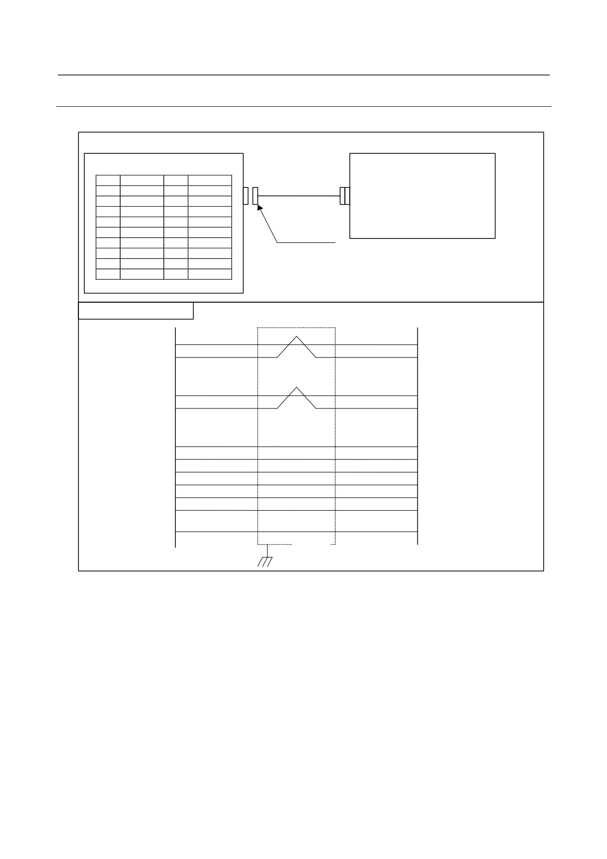
G.5.2.2 Cable J156A (A quad B interface)
Cable J156A is for between Analog servo adapter (JF10nL) and an encoder.
Analog servo adapter
Pulse encoder or separate detector
JF10nL
(PCR-EV20MDV)
1
A
11
J156A
2
∗A
12
0V
3
B
13
4
∗B
14
0V
Connector
FI40-2015S
5
Z
15
Housing
6
∗Z
16
0V
FI-20-CV
7
(+6V)
17
8
(REQ)
18
+5V
+6V and REQ signals are for separate absolute pulse coder.
9
+5V
19
When separate absolute pulse coder is not used, these signals
10
20
+5V
connections are not necessary.
Cable connection (J156A)
JF10nL
1
A
A
2
∗A
∗A
3
B
B
4
∗B
∗B
5
Z
Z
6
∗Z
∗Z
9
+5V
+5V
18
+5V
+5V
20
+5V
+5V
12
0V
0V
14
0V
0V
16
0V
0V
7
(+6V)
(+6V)
8
(REQ)
(REQ)
Shielded
Maximum allowable cable length: 50m
Recommended wire: A66L-0001-0286 (#20AWG x 6 + #24AWG x 3 pairs)
- 441 -
G.ANALOG SERVO ADAPTER
APPENDIX
B-64303EN/03
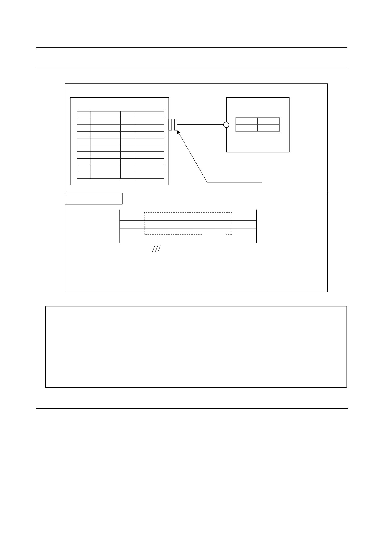
G.5.2.3 Cable J156B (FANUC serial interface)
Cable J156B is for between Analog servo adapter (JF10nL) and pulse encoder / separate detector.
Analog servo adapter
Pulse encoder or separate detector
JF10nL
(PCR-EV20MDT)
1
SD
11
J156B
2
∗SD
12
0V
3
13
4
14
0V
Connector
5
REQ
15
FI40-2015S
Housing
6
∗REQ
16
0V
FI-20-CV
7
(+6V)
17
8
18
+5V
+6V and REQ signals are for separate absolute pulse coder.
9
+5V
19
When separate absolute pulse coder is not used, these signals
10
20
+5V
connections are not necessary.
Cable connection(J156B)
1
SD
SD
2
∗SD
∗SD
5
REQ
REQ
6
∗REQ
∗REQ
9
+5V
+5V
18
+5V
+5V
20
+5V
+5V
12
0V
0V
14
0V
0V
16
0V
0V
(+6V)
(+6V)
Shielded
Maximum allowable cable length: 50m
Recommended wire: A66L-0001-0286 (#20AWG x 6 + #24AWG x 3 pairs)
- 442 -
B-64303EN/03
APPENDIX
G.ANALOG SERVO ADAPTER
G.5.2.4 Cable J37
Cable J37 is for between Analog servo adapter (JA4L) and the battery for separate detector.
Analog servo adapter(basic unit)
Battery for separate detector
JA4L
(PCR-EV20MDT)
1
11
(M3 terminal)
2
12
J37
+
−
3
0V
13
+6V
0V
4
14
5
15
6
16
7
+6V
17
Connector
8
18
PCR-E20FS or PCR-E20FA
9
19
Housing
PCR-V20LA
10
20
Cable connection (J37)
JA4L
7
+
+6V
+6V
3
−
0V
0V
Shielded
Recommended wire
0.2mm2(7/0.18) with shield
NOTE
If the cable is connected to JA4L when the separate absolute pulse coder
battery case contains the battery, the battery voltage is applied to the battery
power supply pin (+6 V) for each of the feedback connectors (JF101L to
JF104L). In this case, if the battery line and 0 V are short-circuited, the battery
may heat up or the protection circuit within Analog servo adapter may fail. First,
make sure the battery case contains no battery or the cable is not connected to
JA4L. Then, complete all cabling work and confirm cables are correctly
connected. Finally, place the battery or connect the cable to JA4L.
G.5.2.5 Detail of signals
(1) VCMD,EC (output)
VCMD and EC are the speed command signals for the servo amplifier. The voltage of VCMD with
respect to EC represents the speed command voltage. (The speed command voltage is enabled only
while the *ENBL signal is on.)
Electrical characteristics
Output voltage: -10V to +10V
Output current: 2mA
Output impedance: 100Ω
- 443 -
G.ANALOG SERVO ADAPTER
APPENDIX
B-64303EN/03
(2)
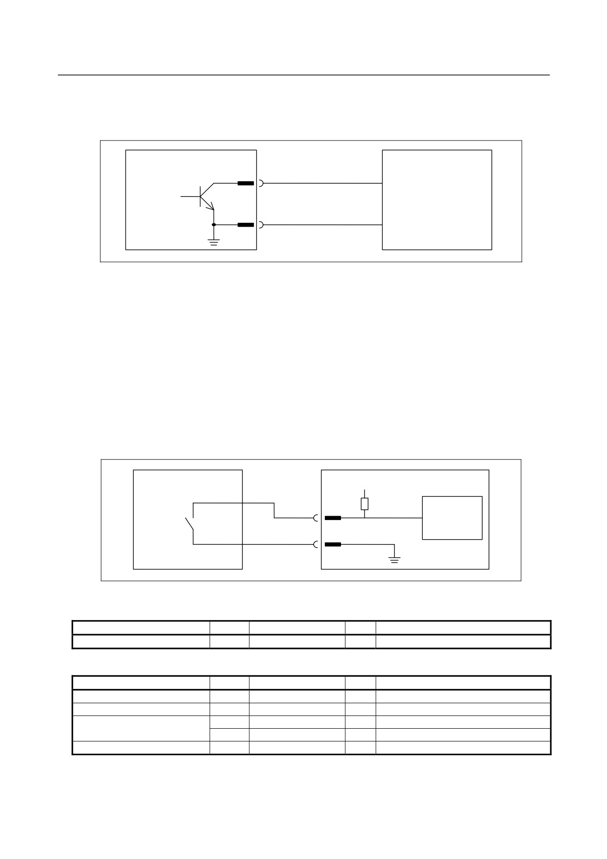
*ENBL (output)
*ENBL is the enable signal for the servo amplifier. While this signal is on (connected to OV), the
VCMD signal is enabled. *ENBL is open collector.
Analog servo adapter
*ENBL
Input ON : connecting 0V
Servo amplifier
Semiconductor
Input OFF : open
contact
0V
Electrical characteristics
Maximum load current when output is on: -10V to +10V
Maximum output voltage when output is on: 6IL (VOlt), where IL: Load current
Withstand voltage when output is of: No more than 24V, including momentary values
Leakage current when output is of: No more than 100μA
(3) OVL (input)
OVL is the overload alarm signal issued by the servo amplifier. When this signal enters the release
state (high level), the CNC assumes that the servo system has entered the overload state, and turns
off the *PRDY and *ENBL signals for the axis. If this signal is not used, connect OVL and 0V to
each other (low level).
When an overload alarm is issued, the servo amplifier must stop the motor regardless of the state of
the VCMD signal.
Servo amplifier
5V
Analog servo adapter
*OVL
Receiver
circuit
0V
Electrical characteristics
Absolute maximum rating
Item
Symbol
Specification
Unit
Supplement
Input voltage range
Vin
-3.6 to +13.6
V
Input characteristics
Item
Symbol
Specification
Unit
Supplement
High level input voltage
VH
3.6 to 10.5
V
Note
Low level input voltage
VL
0 to 1.0
V
High level input current
Iih
+1.5 max
mA
Vin=5V
+8.8 max
mA
Vin=10V
Low level input current
Iil
-8.0 max
mA
Vin=0V
The plus sign (+) of Iih and Iil represents the direction of flow into the receiver, while the
minus sign (-) represents the direction of flow from the receiver.
- 444 -
B-64303EN/03
APPENDIX
G.ANALOG SERVO ADAPTER
NOTE
The input release state is also assumed to be the high level.
(4)
*PRDY (output)
*PRDY is the ready signal, issued by the CNC to the servo amplifier. The electrical characteristics
of this signal are the same as those of *ENBL.
(5)
*VRDY (input)
*VRDY is the ready signal issued by the servo amplifier. When the power to the servo amplifier is
turned on to set the normal startup state, and the *PRDY signal from the CNC is subsequently turned
on, the servo amplifier must immediately turn on (short-circuit) the *VRDY signal. If the servo
amplifier encounters an error, the *VRDY signal must be turned off (released) to report the error to
the CNC. If this signal is not used, connect *VRDY and 0V to each other (low level), and set bit 1
(CVR) of parameter No. 1800 to 1.
If the servo amplifier encounters an error, stop the motor regardless of the state of the VCMD signal.
The electrical characteristics of this signal are the same as those of *ENBL.
(6)
A, *A, B, *B, Z, *Z
These signals are received from the Pulsecoder.
・
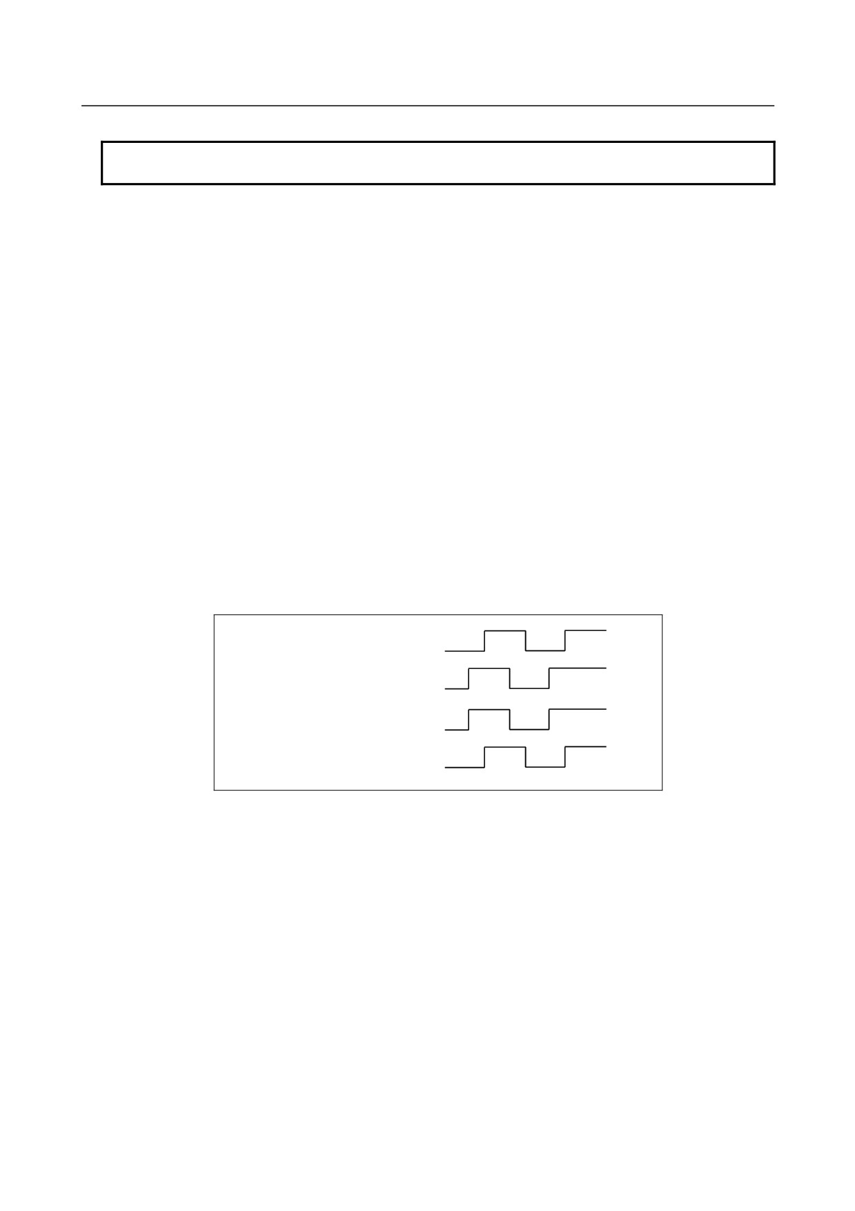
A-phase and B-phase signals (A, *A, B, *B)
The A-phase and B-phase signals are shifted by 90 degrees relative to each other, and are used to
transfer incremental position information. A position is detected, assuming that the direction of
movement is positive while the B-phase signal is advanced, or that the direction of movement is
negative while the A-phase signal is advanced.
Shift in plus direction A phase signal
B phase signal
Shift in minus direction A phase signal
B phase signal
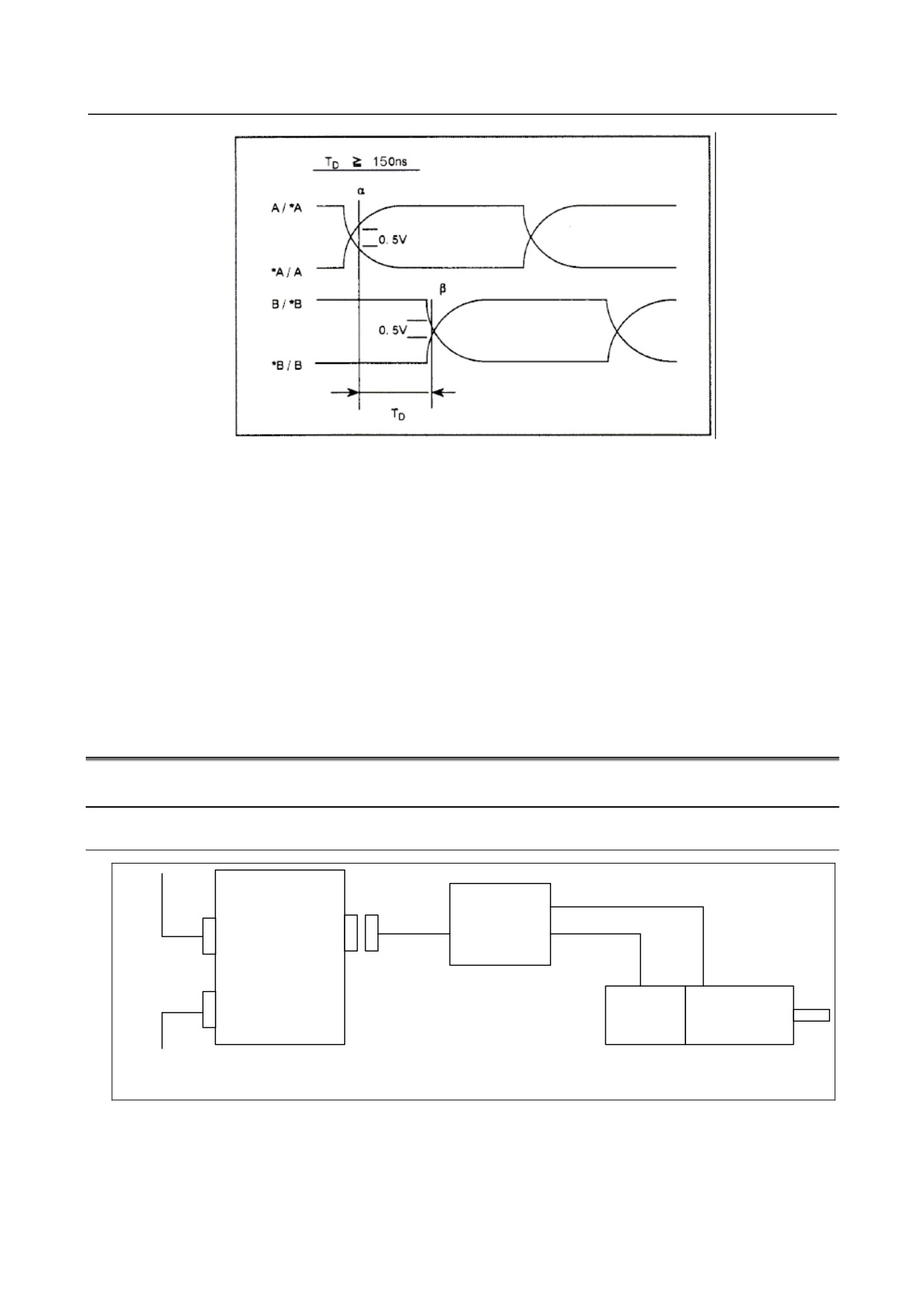
The differential input signals shown below are applied to the connectors. The time duration, TD,
from point α where the relative potential difference between A and *A becomes 0.5 V or more, to
point β where the relative potential difference between B and *B becomes 0.5 V or less, must satisfy
the condition indicated below. (This condition may restrict the maximum speed of movement.)
- 445 -
G.ANALOG SERVO ADAPTER
APPENDIX
B-64303EN/03
• Z-phase signal input
The Z-phase signal (one-rotation signal) requires a signal width of no less than quarter period of the
A-phase or B-phase signal. If the motor does not have this signal, ensure that the machine supplies
this signal. An absolute pulse coder supports the following reference position setting modes, which
do not use the Z-phase signal:
1)
External reference position setting
2)
Butt-type reference position setting
• Input voltage requirments
The voltage of A and B phase signals must meet the following requirments
High level: 2.4V or more
Low level: 0.8V or less
G.6 CONNECTION OF TYPE M ANALOG SERVO INTERFACE
G.6.1 System Structure
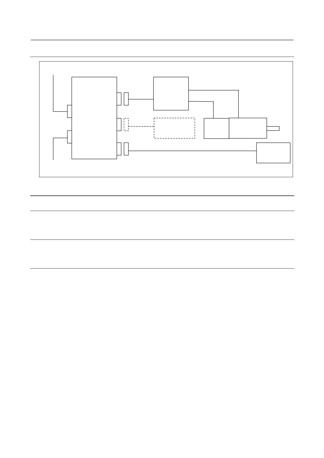
G.6.1.1 In case of using the built-in pulse coder
Analog servo
adapter
Analog
J157
servo
COP10B JV1nL
amplifier
Pulse
Analog
COP10A
encoder
servo motor
FSSB Lower step
- 446 -
B-64303EN/03
APPENDIX
G.ANALOG SERVO ADAPTER
G.6.1.2 In case of using the separate detector
FSSB Upper step
Analog servo
Analog
adapter
servo
amplifier
J158
JV1nL
COP10B
J37
Pulse
Analog
JA4L
Battery
encoder
servo motor
COP10A
J156A/J156B
Separate
JF10nL
detector
FSSB Lower step
G.6.2 Detail of Connection
G.6.2.1 Cables J156A/B
Refer to Subsections G.5.2.2 and G.5.2.3.
G.6.2.2 Cable J37
Refer to Subsection G.5.2.4.
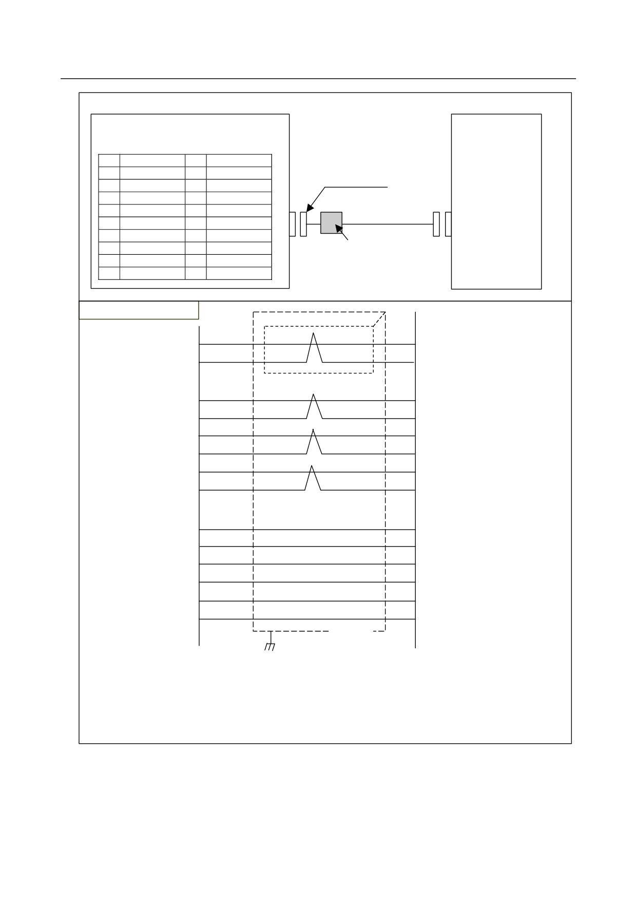
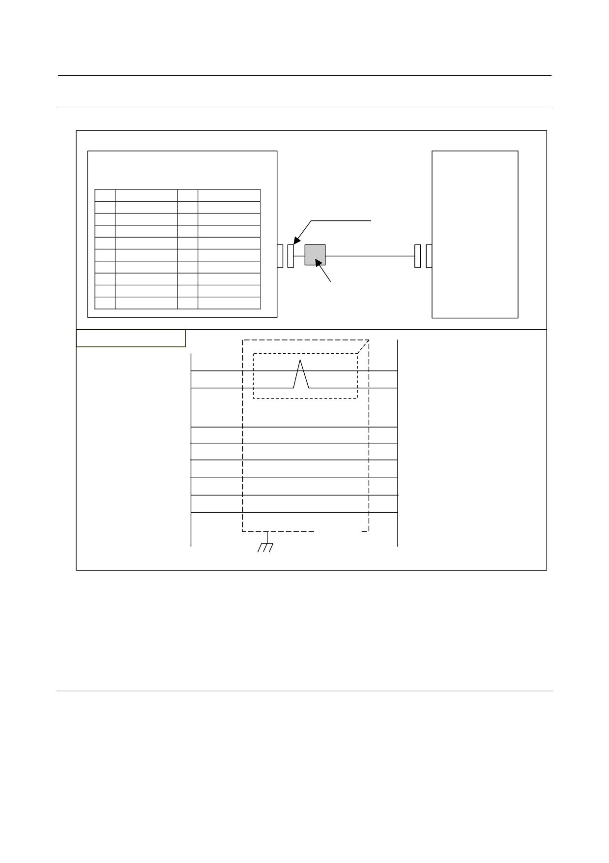
G.6.2.3 Cable J157
Cable J157 is for Analog servo adapter (JV1nL) and analog servo amplifier.
- 447 -
G.ANALOG SERVO ADAPTER
APPENDIX
B-64303EN/03
Analog servo amplifier
Analog servo adapter
Connector
JV1nL
PCR-E20FS
or
(PCR-EV20MDT)
PCR-E20FA
Housing
1
A
11
B
PCR-V20LB
2
*A
12
*B
3
(*ENBL)
13
(OVL)
4
(0V)
14
(0V)
5
Z
15
ALM
J157
6
EC
16
0V
7
VCMD
17
*SRDY
Ferrite core
8
(0V)
18
0V
9
*Z
19
24VOUT
Note)
The pin with ( ) mark
10
*PRDY
20
(*VRDY)
must be open.
Cable connection (J157)
JV1nL
Analog servo amplifier
Analog servo
adapter
7
Individually
VCMD
SPR/SPL
shielded
6
EC
GND
twisted pair
1
PCA
OA+
2
*PCA
OA−
11
PCB
OB+
12
*PCB
OB−
5
PCZ
OZ+
9
*PCZ
OZ−
17
*SRDY
S−RDY
15
ALM
ALM
10
*PRDY
SRV−ON
19
24VOUT
COM+
18
0V
COM−
16
0V
GND
Shield
Maximum allowable cable length:50m (cable length has limitation by voltage drop)
Recommended wire A66L-0001-0206
(Individually shielded twisted pair #24AWG x 3 pairs + twisted pair #24AWG x 7 pairs)
The external cable diameter is ∅11, preventing the use of the cable, as is, with connector case PCR-V20LB (∅8).
Peel backs the sheath at the point where the cable meets the connector to reduce the cable diameter.」
Recommended ferrite core:TDK ZCAT2032-0930
Set ferrite core near Analog servo adapter.
- 448 -
B-64303EN/03
APPENDIX
G.ANALOG SERVO ADAPTER
G.6.2.4 Cable J158
Cable J158 is for Analog servo adapter (JV1nL) and analog servo amplifier.
Analog servo adapter
Analog servo amplifier
Connector
JV1nL
PCR-E20FS
or
(PCR-EV20MDT)
PCR-E20FA
Housing
1
(PCA)
11
(PCB)
PCR-V20LB
2
(*PCA)
12
(*PCB)
3
(*ENBL)
13
(OVL)
4
(0V)
14
(0V)
5
(PCZ)
15
ALM
J158
6
EC
16
0V
7
VCMD
17
*SRDY
8
(0V)
18
0V
Ferrite core
9
(*PCZ)
19
24VOUT
Note) The pin with () mark
10
*PRDY
20
(*VRDY)
must be open.
Cable connection (J158)
JV1nL
Analog servo amplifier
Analog servo
7
SPR/SPL
Individually
VCMD
adapter
shielded
6
GND
EC
twisted pair
17
S−RDY
*SRDY
15
ALM
ALM
10
SRV−ON
*PRDY
19
COM+
COM+
18
COM−
0V
16
GND
0V
Shield
Maximum allowable cable length:50m (cable length has limitation by voltage drop)
Recommended wire A66L-0001-0206
(Individually shielded twisted pair #24AWG x 3 pairs + twisted pair #24AWG x 7 pairs)
The external cable diameter is ∅11, preventing the use of the cable, as is, with connector case PCR-V20LB (∅8).
Peel backs the sheath at the point where the cable meets the connector to reduce the cable diameter.
Recommended ferrite core:TDK ZCAT2032-0930
Set ferrite core near Analog servo adapter.
G.6.2.5 Detail of signals
(1) VCMD, EC (output)
VCMD and EC are the speed command signals for the servo amplifier. Refer to Subsection G.5.2.5,
“Details of signals.”
(2) A,*A,B,*B,Z,*Z (input)
These signals are received from the pulse coder. Refer to Subsection G.5.2.5, “Details of signal.”
- 449 -
G.ANALOG SERVO ADAPTER
APPENDIX
B-64303EN/03
(3)
*PRDY (output)
*PRDY is the ready signal, issued by Analog servo adapter to the servo amplifier. Refer to
Subsection G.5.2.5, “Details of signal.”
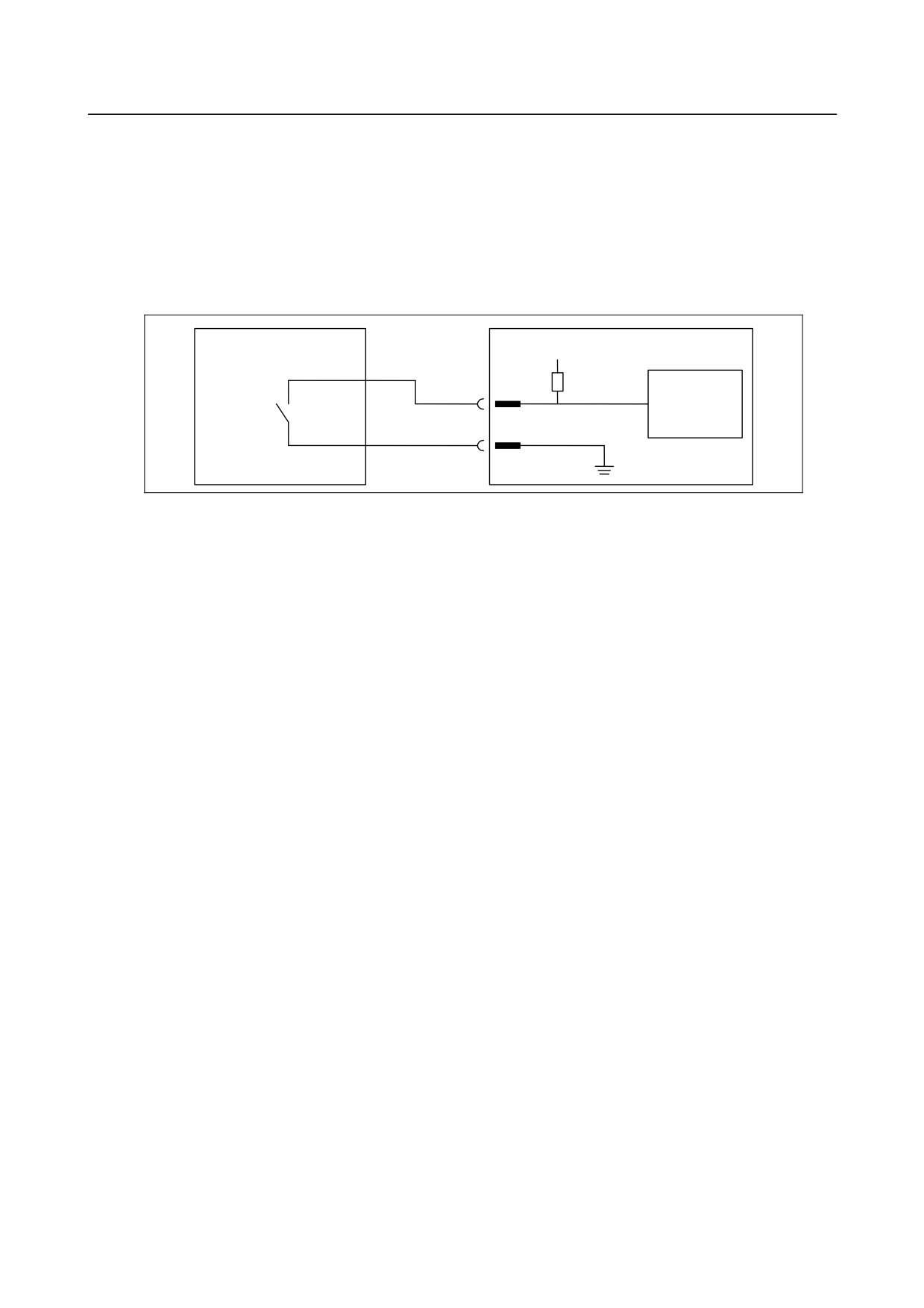
(4) ALM (input)
ALM is the alarm signal, issued by the servo amplifier to Analog servo adapter. While this signal is
off (open or high level), the CNC assumes that the servo system has entered the alarm state. When
this signal is not used, connect ALM and 0V to each other (low level).
Servo amplifier
Analog servo adapter
24V
ALM
Receiver
circuit
0V
Electrical characteristics
Contact capacity: 30VDC, 16mV or greater
Open-circuit contact-to-contact leakage: 1mA or less (for 26.4V)
Closed-circuit contact-to-contact voltage drop: 2V or less (for8.5mA, including a voltage
drop across the cable)
(5)
*SRDY (input)
*SRDY is the ready signal, issued by the servo amplifier to Analog servo adapter. While this signal
is on (short or low level), the CNC assumes that the servo system has entered the ready state.
Electrical characteristics are as same as ALM.
(6)
24VOUT (output)
24VOUT is 24VDC power for the servo amplifier from Analog servo adapter.
24V±10%,Up to 250mA / one JV1n connector (Up to 500mA / 1 unit)
Pay careful attention to the voltage drop caused by the cable resistance for the specifications of the
servo amplifier.
- 450 -
B-64303EN/03
APPENDIX
G.ANALOG SERVO ADAPTER
G.7 POWER AND HEAT GENERATED
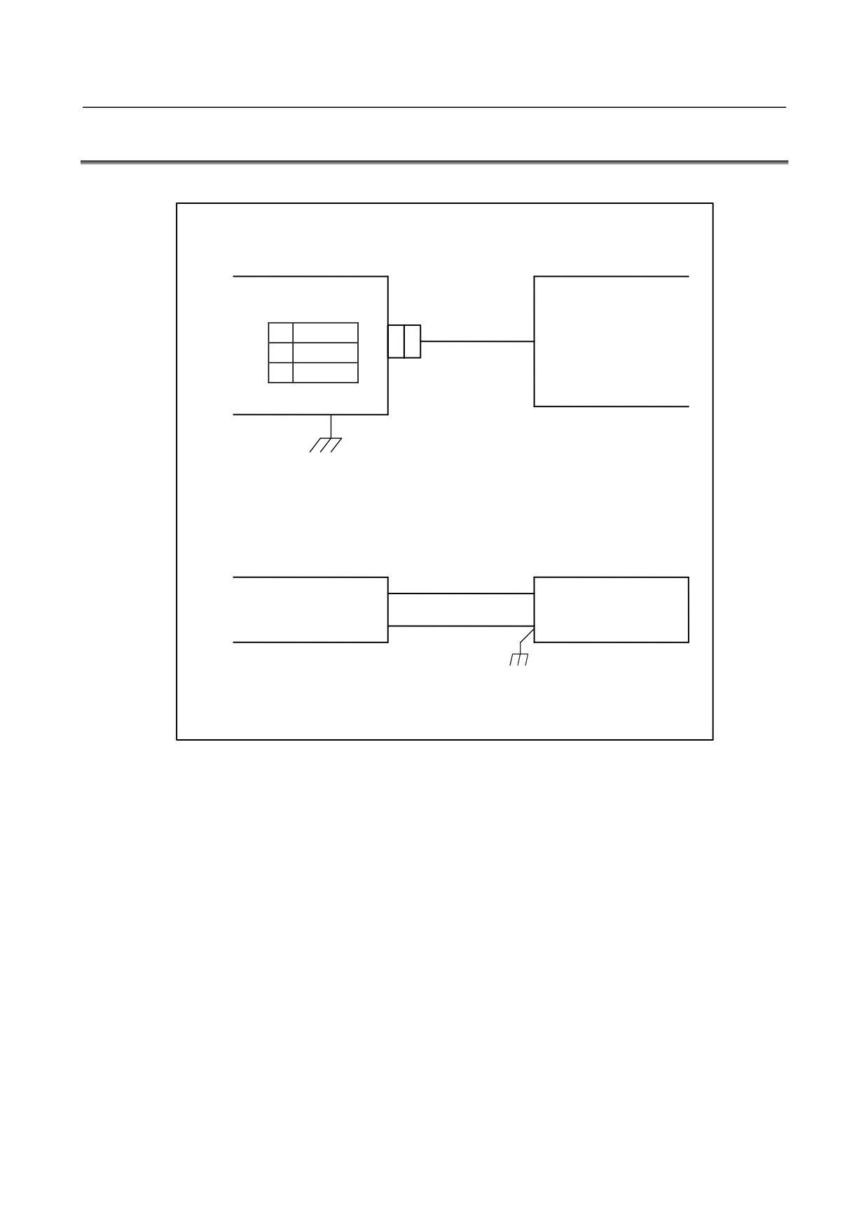
The power of Analog servo adapter must be supplied from external power supply 24VDC.
Analog servo adapter (basic)
External power supply
CP11L
DC24V±10%
1
+24V
(including an
2
0V
instantaneous value and
3
ripple)
GND
Cable
CP11L
AMP Japan
1-178288-3(Housing)
External power supply
1-175218-5(Contact)
+24V(1)
0V(2)
Recommended cable : A02B-0124-K830(5m)
With M3 terminal for External power supply
24VDC are supplied through the connector CP11L. The power can be supplied from CP11M to the next
unit.
Be sure to ground the 0-V line of the power supply to Analog servo adapter. In addition, keep any noise
source (such as an AC power cable and contactor) away from the power line of Analog servo adapter as
far as possible to prevent noise from being picked up through the power line.
- 451 -
G.ANALOG SERVO ADAPTER
APPENDIX
B-64303EN/03
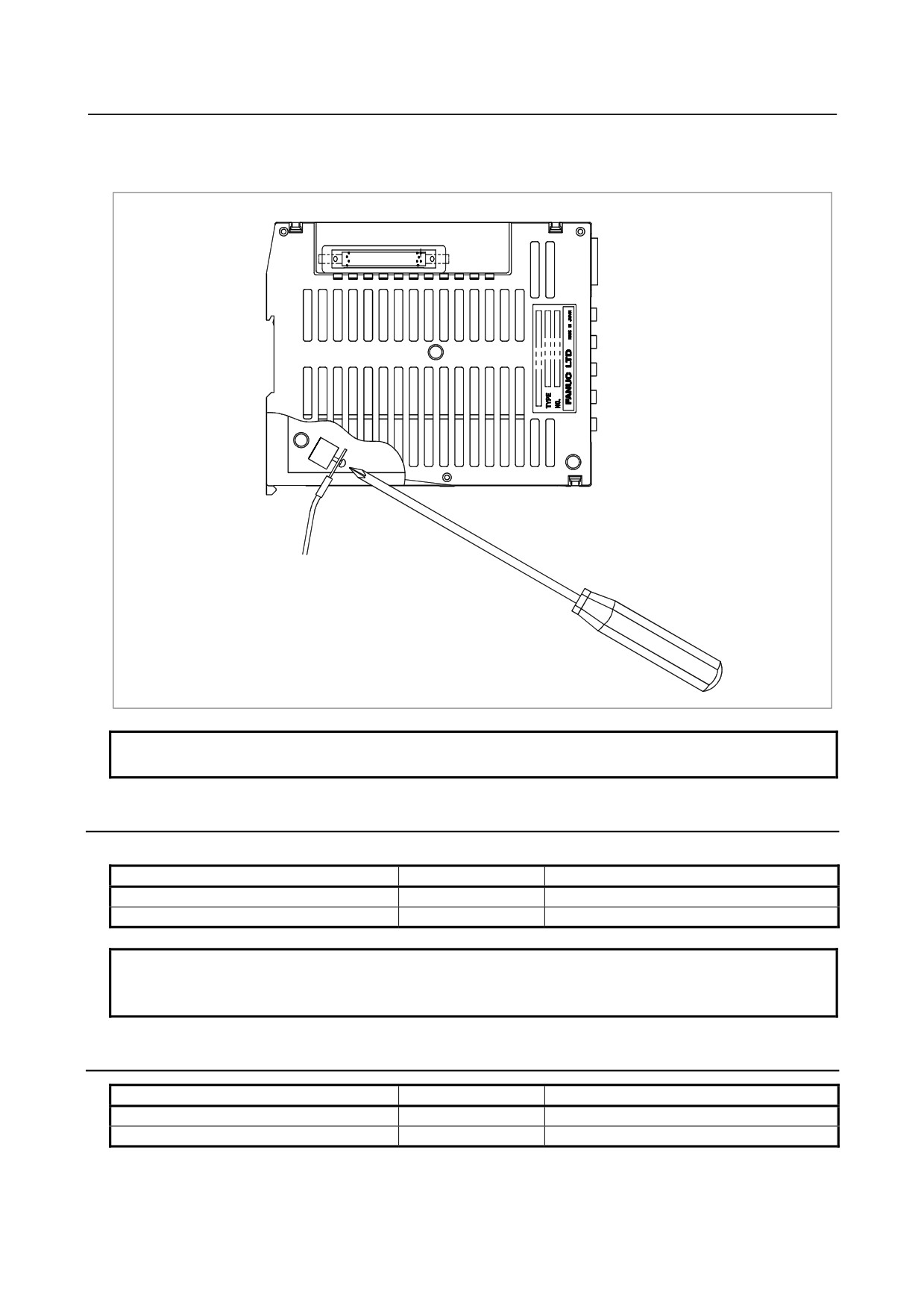
Secure the ground line to the ground terminal (GND) for signals of Analog servo adapter, which is
located at the bottom of the unit, with an M3 screw as shown in the figure below. Connect the ground
line to the ground plate of the cabinet.
GND
To ground plate of cabinet
NOTE
The torque with which a screw is tightened is 5 kgf × cm or less.
G.7.1 Power Supply Rating
Power Supply of 24 VDC±10% (including instantaneous voltage and ripple voltage )
One basic unit
One basic unit + one expansion unit
Type F
0.7A
1.0A
Type M
1.2A(Note)
2.0A(Note)
NOTE
In case of type M, 24VDC 0.25A per one axes is included for analog servo
amplifier.
G.7.2 Heat Generated
One basic unit
One basic unit + one expansion unit
Type F
10W
14W
Type M
17W
28W
- 452 -
B-64303EN/03
APPENDIX
G.ANALOG SERVO ADAPTER
G.8 SELECT SWITCH SW1
The input level of ready signal (input) and alarm signal (input) of type F analog servo interface are
different from the input level of ready signal (input) and alarm signal (input) of type M analog servo
interface. Type F or Type M is decided by select switch SW1.
Select switch SW1 has two positions “F” and ”M” (See Note).
SW1
Ready signal
Alarm signal
Remarks
F side
*VRDY
OVL
Type F analog servo interface (5VDC)
M side
*SRDY
ALM
Type M analog servo interface (24VDC)
NOTE
Actual select switch SW1 has three positions. Up side to base PCB is M, middle
and down side is F.
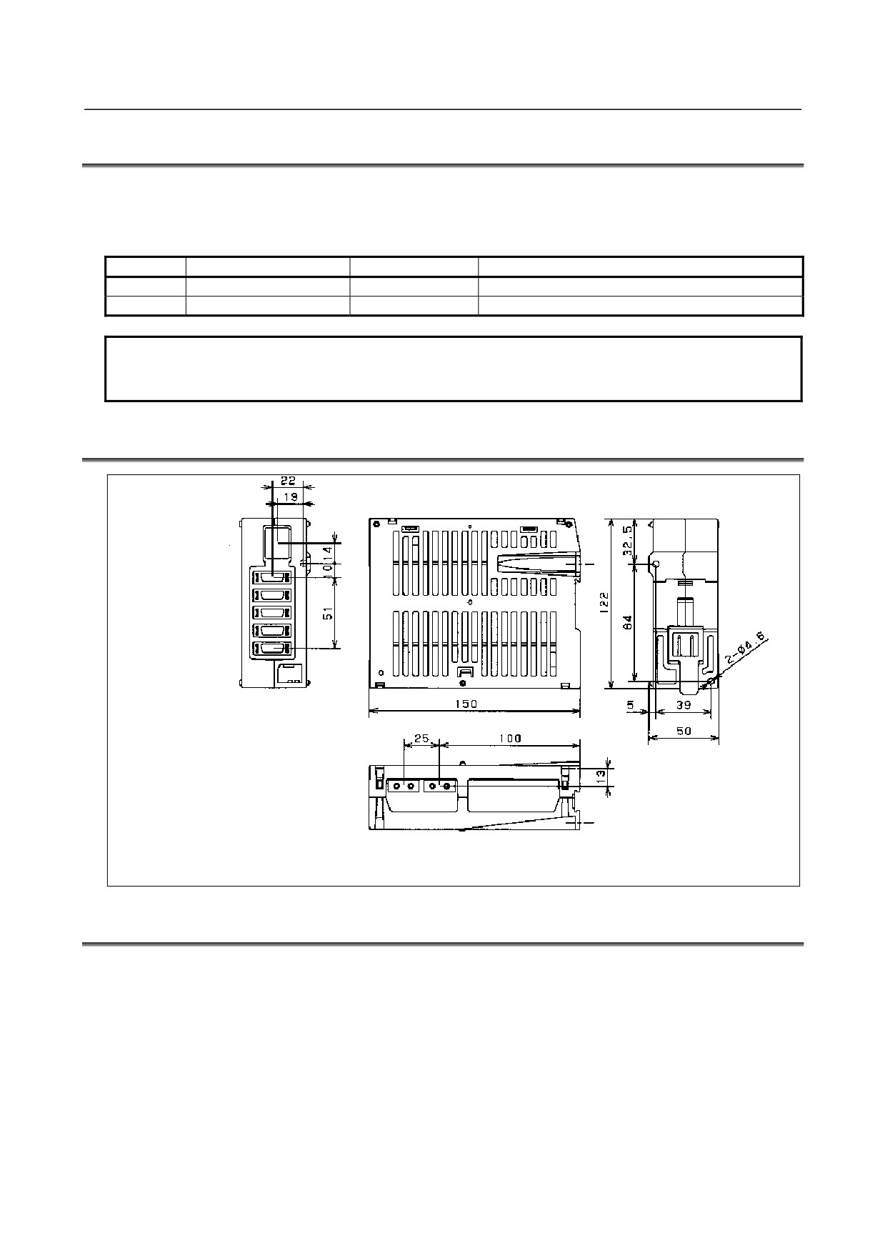
G.9 EXTERNAL DIMENSION
Additional
Basic
CP11L/M
JV13L
JV11L
JF103L
JF101L
JV14L
JV12L
JF104L
JF102L
JA4M
JA4L
COP10B/10A
G.10 NOTICE
• The maximum number of interface units like Analog servo adapter or a separate detector interface
unit that can be connected to one FSSB line is two.
When Analog servo adapter is connected to the FSSB line, the number of the separate detector
interface unit can be connected to the same FSSB line is one.
• Analog servo adapter has four encoder interfaces. The unused one can be used for full closed
control.
• Analog servo adapter does not apply “CE Marking”.
- 453 -

G.ANALOG SERVO ADAPTER
APPENDIX
B-64303EN/03
• When system alarm is occurred on CNC or communication alarm between CNC and Analog servo
adapter is occurred, the signals *ENBL and *PRDY will be OFF. When the power of CNC or
Analog servo adapter is turn off, the signals *ENBL and *PRDY will be OFF.
• The way to install this unit is similar to the one of the separate detector interface unit. Please refer to
the Section 7.2.
• The sequence of power on/off is similar to the separate detector interface unit. Refer to the
Subsections 4.2.3 and 4.2.4. But if the position feedback with A quad B interface is used and the
+5VDC power is not supplied to it from Analog servo adapter, it is necessary to turn on the power
for it before the power for Analog servo adapter is turned on. Furthermore, in this situation, it is also
necessary that the A quad B interface signals of the separate detector become stable before turning
on Analog servo adapter.
G.11 PARAMETER SETTING
(1) At emergency stop, turn on the power of CNC.
(2) Follow the procedure below to set parameters concerned with FSSB.
In the case of using Analog servo adapter, the FSSB automatic setting function is not available. It is
necessary to set the value of No.1023, No.1815, No.1905, No.14340 to14349, No.14376 to 14391
and No.1936 to 1937 in the manual setting No.2 mode. Refer to “FSSB setting” of the connection
manual (function edition) about the detail of the setting.
When this parameter is set, Analog servo adapter is basically treated in the similar way to the
separate type detector interface unit. (After this, Analog servo adapter and the separate type detector
interface unit are called “an interface unit”.)
Follow the explanation below and the Parameter Manual
(B-64310EN) of CNC and set the
appropriate value.
•
Setting of servo axis number
No.
1023
Number of the servo axis for each axis
[Data type] Byte axis
[Valid data range] 1,2,3,…controllable axis number
Set the servo axis number for each axis. Refer to the “FSSB setting” of Connection
Manual (Function) (B-64303EN-1).
•
Setting of the position detector
No.
7
6
5
4
3
2
1
0
1815
APC
APZ
APC 0: Position detector is other than absolute pulse coder.
1: Position detector is absolute pulse coder.
APZ Zero position of absolute pulse coder is:
0: Not established.
1: Established. (Automatically set to 1 after the zero position is established.)
- 454 -
B-64303EN/03
APPENDIX
G.ANALOG SERVO ADAPTER
•
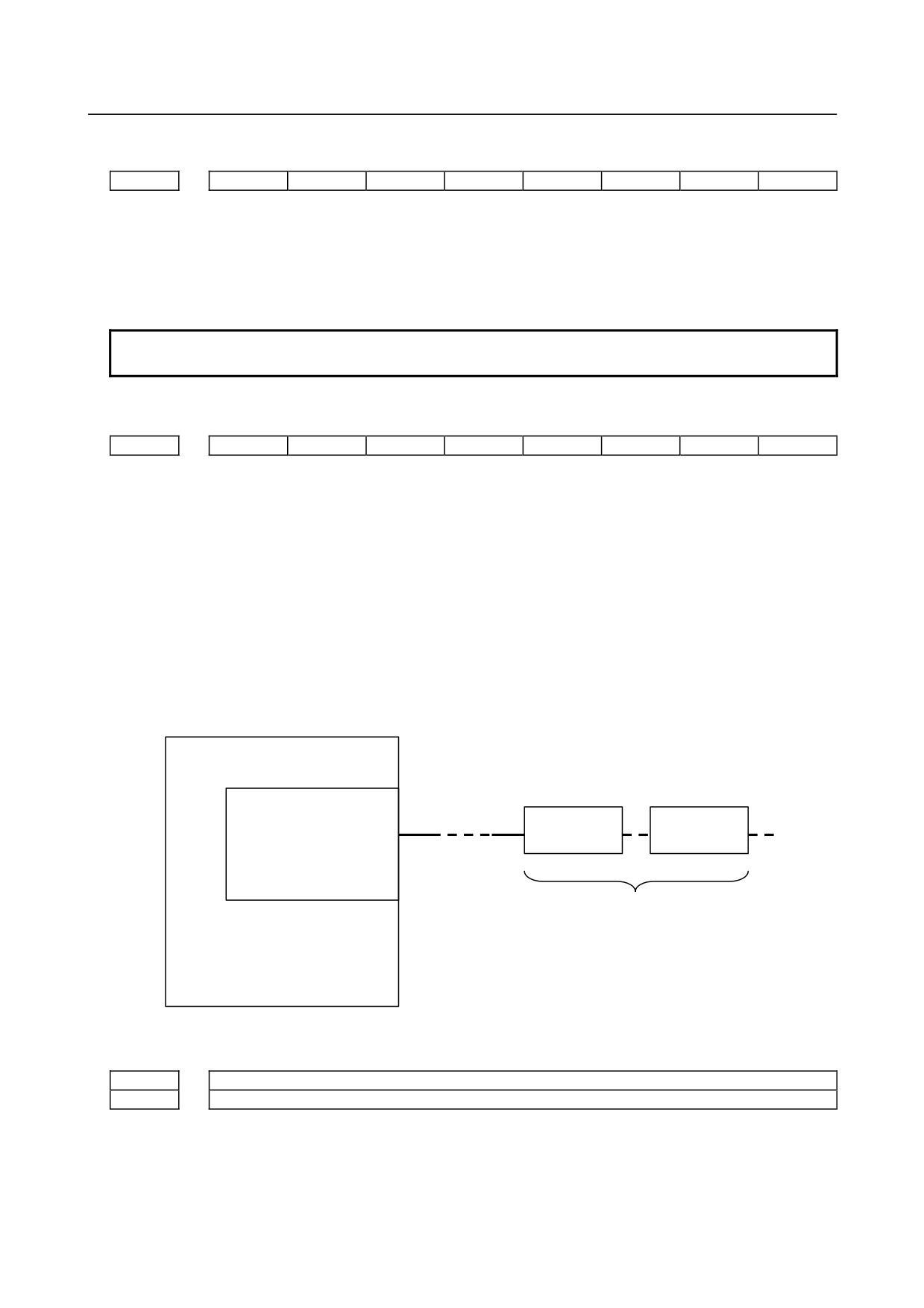
FSSB manual setting
No.
7
6
5
4
3
2
1
0
1902
FMD
[Data type] Byte axis
FMD The setting mode of FSSB is
0: Automatic.
1: Manual setting 2.
NOTE
If you want to use Analog servo adapter, set 1.
•
Setting of bit parameter
No.
7
6
5
4
3
2
1
0
1905
PM2
PM1
[Data type] Bit axis
PM1 The first interface unit is:
0: Not used.
1: Used.
PM2 The second interface unit is:
0: Not used.
1: Used.
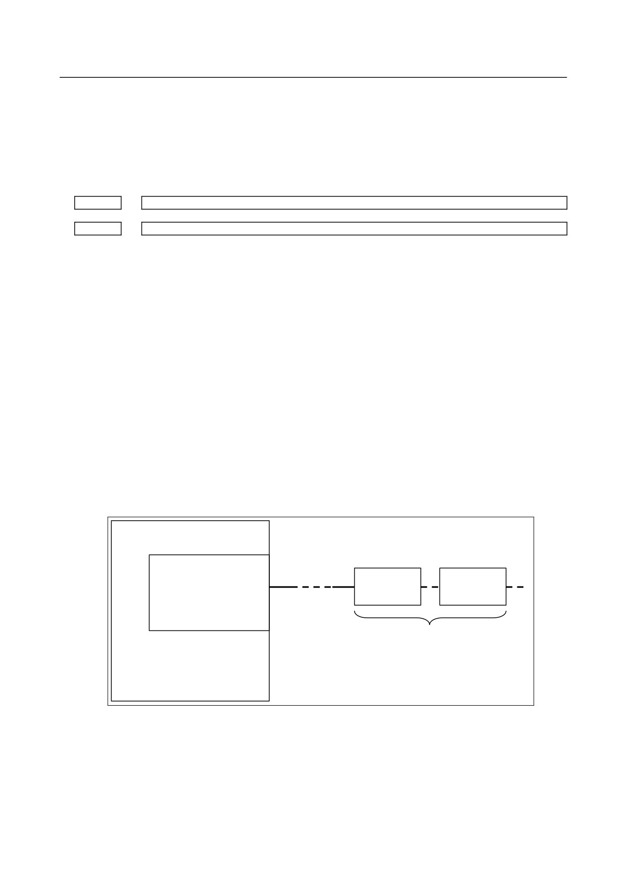
The interface unit that is connected to the FSSB line on a servo card and is near the CNC
is the first interface unit (1st IF unit). Another one connected to the FSSB line is the
second interface unit (2nd IF unit).
CNC
Servo card
FSSB line
1st IF unit
2nd IF unit
COP10A-1
PM1
PM2
Two IF units (max)
•
Setting connector number
No.
1936
Connector number of the first interface unit
1937
Connector number of the second interface unit
[Data type] Byte axis
[Valid data range] 0 to 3 (in case of Analog servo adapter)
0 to 7 (in case of separate type detector interface unit)
- 455 -
G.ANALOG SERVO ADAPTER
APPENDIX
B-64303EN/03
In case of using interface unit, set the value, which subtracts 1 from the connector number
of each axis. (In case of using Analog servo adapter, set 0 to 3 to the axes connected with
connector JV1nL to JV4nL.)
Set 0 to the axis without interface unit.
It is possible to use any connectors at any axis.
•
Setting Address Conversion Table for slave number
No.
14340
ATR value corresponding to slave 01 on the FSSB line
to
14349
ATR value corresponding to slave 10 on the FSSB line
[Data type] Byte
[Valid data range] 0 to 7, 64, -56, -96
The amplifier or interface unit connected to CNC by the optical cable is called “Slave”.
Each one axis servo amplifier or one interface unit (with or without the additional unit)
consists of one slave. Two axes amplifier consists of two slaves and three axes amplifier
consists of three slaves.
The analog servo amplifier is numbered as if it was connected from the terminal slave
(the most far slave from CNC). Each one-axis analog servo amplifier is numbered one
slave number. For example, if the terminal unit connected to FSSB is slave 5, the analog
servo amplifiers are numbered from 6. (Refer to the example described later.)
This parameter is set as follows.
-
In case of amplifier (including analog amplifier):
Set a value obtained by subtracting 1 from the setting of parameter No.1023 for the
axis to which the amplifier is assigned.
-
In case of interface unit:
Set 64 for 1st interface unit and set -56 for the 2nd interface unit respectively.
Please see below figure.
CNC
Servo card
FSSB line
1st IF unit
2nd IF unit
COP10A-1
ATR=64
ATR= -56
Two IF units (max)
-
In case of no slave:
Set -96.
- 456 -
B-64303EN/03
APPENDIX
G.ANALOG SERVO ADAPTER
•
Setting Address Conversion Table for connector
No.
14376
ATR value corresponding to connector 1 on the 1st interface unit
to
14383
ATR value corresponding to connector 8 on the 1st interface unit
[Data type] Byte
[Valid data range] 0 to 7 and 32
No.
14384
ATR value corresponding to connector 1 on the 2nd interface unit
to
14391
ATR value corresponding to connector 8 on the 2nd interface unit
[Data type] Byte
[Valid data range] 0 to 7 and 32
Each of these parameters sets the value(ATR value) of the address translation table
corresponding to each connector on a interface unit.
In each of these parameters, set a value obtained by subtracting 1 from the setting of
parameter No.1023 for the axis connected to a connector on an interface unit.
When there is an axis for which bit 6 or 7 of parameter No.1905 is set to use an interface
unit, set 32 for those connectors that are not used.
(3) Turning off/on the power to CNC
The description of setting continues to 4. Servo initial setting.
(Reference)
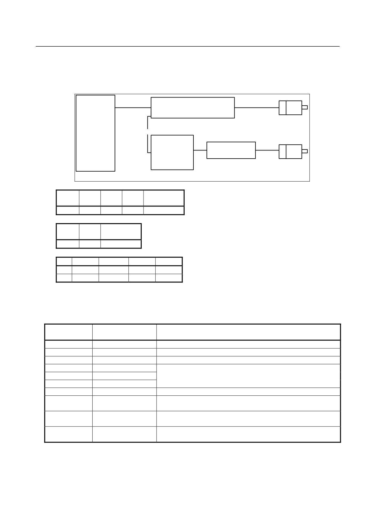
FSSB Setting example in case of using Analog servo adapter
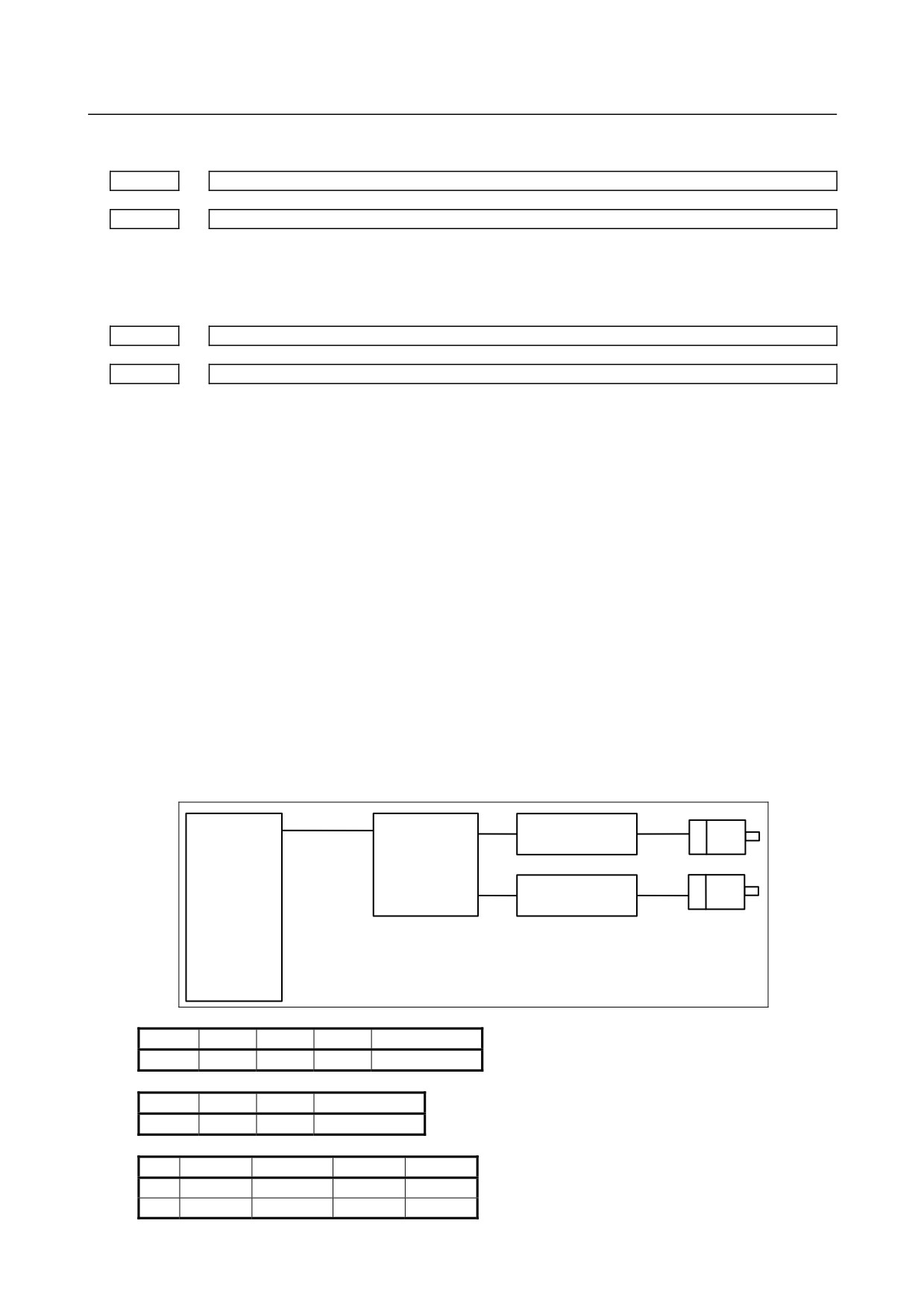
[Example 1 : in case of two analog servo axis]
Analog servo adapter is slave 1. Analog servo amplifiers are considered as they are connected after
Analog servo adapter. So they are slaves 2 and 3.
FSSB
X axis
JV11L
Analog servo
Analog servo
amplifier 1
adapter
Slave 2
(Basic unit)
Y axis
JV12L
Analog servo
amplifier 2
CNC
Slave 1
Slave 3
No.
14340
14341
14342
14343 to 14349
Value
64
0
1
-96
No.
14376
14377
14378 to 14383
Value
0
1
32
No.
No.1023
No.1905
No.1936
No.1937
X
1
01000000
0
0
Y
2
01000000
1
0
- 457 -
G.ANALOG SERVO ADAPTER
APPENDIX
B-64303EN/03
[Example 2 : in case of one digital and one analog servo axis]
Digital servo amplifier is slave 1 and Analog servo adapter is slave 2. Analog servo amplifier is
slave 3.
FSSB
X axis
Digital servo amplifier
Slave 1
FSSB
CNC
Analog servo
Analog amplifier
JV11L
Y axis
adapter
(Basic unit)
Slave 3
Slave 2
14343 to
No.
14340
14341
14342
14349
Value
0
64
1
-96
14377 to
No.
14376
14383
Value
1
32
No.
No.1023
No.1905
No.1936
No.1937
X
1
00000000
0
0
Y
2
01000000
0
0
(4)
Initial setting of servo parameter
Set the following of analog servo axis.
Parameter
Description
Data
number
No.2000
Automatic setting
00000000
No.2020
Motor type
252
No.2001
AMR
00000000
No.1820
CMR
Set the value similar to the one of digital servo according to mechanical
No.2084
F × FG (Numerator)
system.
No.2085
F × FG (Denominator)
No.2022
Rotation direction
111 (CCW) or -111 (CW)
No.1821
Reference counter size
Set the number (after F×FG) of pulse per one motor revolution as digital
servo.
No.2023
Feedback pulse for
Set value = 1536.797 × E
velocity detection
E : the voltage (V) proportional to the 1000min-1 velocity command
No.2024
Feedback pulse for
Set the number (before F × FG) of pulse per one motor revolution as
position detection
digital servo.
(5)
Power OFF/ON
(6)
Setting to validate the analog servo interface function
Set the following of analog servo axis.
- 458 -
B-64303EN/03
APPENDIX
G.ANALOG SERVO ADAPTER
No.
7
6
5
4
3
2
1
0
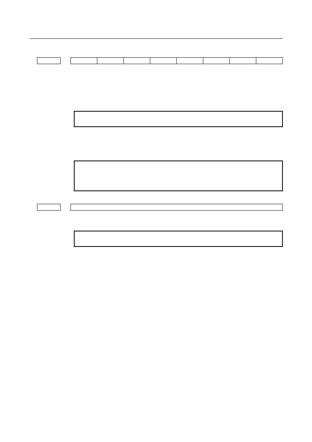
2009
ANALOGG
SERDMY
[Data type] Bit axis
SERDMY The serial feedback dummy function is:
0: Invalidated.
1: Validated.
NOTE
In case of analog servo axis, set 1.
ANALOG The analog servo interface function is:
0: Invalidated.
1: Validated.
NOTE
In case of analog servo axis, set 1.
After setting this bit, please turn off the power of CNC more than
one time.
No.
2165
Maximum amplifier current
[Data type] Byte axis
NOTE
In case of analog servo axis, set 0.
When the initial setting of servo shown in previous section is done, 45 is set to this
address automatically. But clear this parameter to be 0. (If this parameter of analog servo
axis is not 0, the combination alarm of motor and amplifier will emerge.)
- 459 -
ADDITIONAL INFORMATION
FANUC Series 0i-MODEL D/0i Mate-MODEL D
The correction of CONNECTION MANUAL (HARDWARE)
(B-64303EN/03
j
P Type of applied technical documents
FANUC Series 0i-MODEL D/0i Mate-MODEL D
Name
The correction of CONNECTION MANUAL (HARDWARE)
Spec.No. /Version
B-64303EN/03
Q Summary of change
New,Add,
Applicable
Group
Name/Outline
Correct,Delete
Date
Basic
Function
Optional
Function
Unit
Maintenance
Parts
Notice
This document describes the correction of the diagram of cable wiring for
Correction
position coder in item 6.3.
Others
TITLE
FANUC Series 0i-MODEL D/0i Mate-MODEL D
The correction of CONNECTION MANUAL
(HARDWARE)
DRAW. NO.
C
01
10.02.15
H.Otsuki
First issued.
B-64303EN/03-1
SHEET
EDIT.
DATE
DESIG.
DESCRIPTION
1/2
6.3
POSITION CODER
CNC
JA41 (main board)
Signal name
Description
FI80-20P, DF1R020WB1
SC,*SC
Position coder C phase signal
(PCR-EV20MDT)
PA,*PA
Position coder A phase signal
P
(
)
11
(
)
PB,*PB
Position coder B phase signal
2
(
)
12
0V
3
(
)
13
(
)
4
(
)
14
0V
5
PA
15
SC
6
*PA
16
0V
7
PB
17
*SC
8
*PB
18
+5V
9
+5V
19
(
)
10
(
)
20
+5V
Cable connection
JA41
5
PA
A(PA)
6
*PA
N(*PA)
7
PB
C(PB)
8
*PB
R(*PB)
15
SC
B(PZ)
17
*SC
P(*PZ)
9,18,20
+5V
H
12,14,16
0V
K
Shield
Ground plate
Recommended cable connector:
PCR-E20FA (manufactured by Honda Tsushin Kogyo)
FCN-247J020-G/E (manufactured by Fujitsu)
52622-2011 (manufactured by Molex Japan)
Recommended cable specification:
A66L-0001-0286 (#20AWG x 6 + #24AWG x 3), max. length 20 m
NOTE
1
The signals enclosed by parentheses ( ) are used for serial spindles.
These
signals are not used for analog spindles.
2
The 15-pin soldering connector (FI40B-2015S (conventionally, FI40-2015S))
manufactured by Hirose Electric cannot be used for the connector on the cable
side.
3
The upper connector specification of JA41 is for the LCD-mounted type.
The lower connector name in parentheses is for the stand-alone type.
TITLE
DRAW. NO.
C
B-64303EN/03-1
SHEET
EDIT.
DATE
DESIG.
DESCRIPTION
2/2
FANUC Series 0i / 0i Mate-MODEL D
The additional matter of CONNECTION MANUAL (HARDWARE)
1.
Type of applied technical documents
FANUC Series 0i / 0i Mate-MODEL D
Name
CONNECTION MANUAL (HARDWARE)
Spec. No.
B-64303EN/03
/ Version
2.
Summary of change
New, Add.,
Applicable
Group
Name / Outline
Correct, Del.
Date
Basic
Function
Optional
Function
Unit
Maintenance
Parts
Note for INSTALLATION CONDITION FOR UL/CSA RECOGNITION
Notice
is added as Section 3.8.
Correction
Another
TITLE
FANUC Series 0i / 0i Mate-MODEL D
CONNECTION MANUAL (HARDWARE)
Adding Note for INSTALLATION CONDITION
FOR UL/CSA RECOGNITION
DRAW. NO
CUST.
01
10.02.26
Li
First issue
B-64303EN/03-01
Edit.
DATE
Design
Description
SHEET
1/ 2
"Note for INSTALLATION CONDITION FOR UL/CSA RECOGNITION" is added as Section 3.8
3.8
INSTALLATION CONDITION FOR UL/CSA RECOGNITION
1.
Outline
For UL/CSA recognition of the product, FANUC Series 0i / 0i Mate-MODEL D shall be
installed after due considerations on UL/CSA requirements.
2.
Notes on the installation conditions for UL/CSA recognition are given to the follows.
■
Only for LCD mounted type CNC
• Set up the CNC unit on a flat surface of a Type 1 Enclosure *1.
(*1. Type 1 Enclosure is a cabinet type in accordance with UL requirement.)
■
Both for LCD mounted type CNC and stand-alone type CNC
• Set up the CNC unit to the enclosure under the Pollution degree 2 *2 environment.
(*2. Pollution degree 2 is an environment level in accordance with UL requirement.)
• Maximum surrounding air temperature rating: +60°C *3
(*3. This temperature rating is a condition of UL evaluation for recognition. However, for
long-term reliability, the cabinet should be actually designed based on the maximum
operating ambient temperature that described in the subsection
3.1.2 for LCD
mounted type and subsection 12.5.1 for stand-alone type in the connection manual
(B-64303EN).)
• Power supply unit for this unit must have an isolating device and the DC 24 Volt
output must be isolated from AC mains supply.
(This isolation can be achieved with the use of the isolating DC power supply unit that
complies with UL/CSA standard.)
TITLE
DRAW. NO.
CUST.
B-64303EN/03-01
Edit.
DATE
Design
Description
SHEET
2 / 2
FANUC Series 0i-MODEL D/0i Mate-MODEL D
The modification of CONNECTION MANUAL(HARDWARE)
1. Type of applied technical documents
FANUC Series 0i-MODEL D/0i Mate-MODEL D
Name
CONNECTION MANUAL(HARDWARE)
Spec.No./Version
B-64303EN/03
2. Summary of change
Group
Name / Outline
New, Add,
Applicable
Correct,
Date
Delete
Basic
Function
Optional
Function
Unit
Maintenance
parts
Notice
Correction
Another
Item 10.1 STOP MODES
Correct
Immediately
Item 10.5. EMERGENCY STOP SIGNAL
ç
ç
ç
ç
TITLE
FANUC Series 0i-MODEL D/
0i Mate-MODEL D
ç
ç
ç
ç
The modification of CONNECTION
ç
ç
ç
ç
MANUAL
ç
ç
ç
ç
ċęĈĞõçĕĖõ
ĊĜĚě.
01
OKITA
K.Ito
B-64303EN/03-3ç
11.01.20
New Issue
ĚďČČěç
ČċĐěõ
ċĈěČç
ċČĚĐĎõç
ċČĚĊęĐėěĐĖĕç
1 / 7
ç
ç
Item 10.1 STOP MODES
Modified as Following.
If the control unit enters the alarm state, the servo and spindle motors stop (Note).
NOTE
A servo motor attached to a vertical axis or spindle which is not manufactured by FANUC
may not stop. And, a stop of the spindle motor depends on a Ladder program.
There are the following stop modes:
1.
Stop by shutting off the motor power
2.
Controlled stop without shutting off the motor power
3.
Stop by shutting off the motor power after a controlled stop
A controlled stop is the quickest. However, a stop may be made by immediately shutting off the
motor power for safety reasons.
WARNING
Pressing the RESET key stops the running program. As a result, the servo axis stops and
the spindle axis remains rotating without changing the speed. The RESET key may not
function due to a MDI failure or the like, so, for safety, use the emergency stop button
instead of the RESET key to stop the motor safely. When a failure of the control unit,
machine contact, or connection is also assumed, further safety actions must be taken.
ç
ç
ç
ç
TITLE
FANUC Series 0i-MODEL D/
0i Mate-MODEL D
ç
ç
ç
ç
The modification of CONNECTION
ç
ç
ç
ç
MANUAL
ç
ç
ç
ç
ċęĈĞõçĕĖõ
ĊĜĚě.
ç B-64303EN/03-3ç
ĚďČČěç
ČċĐěõ
ċĈěČç
ċČĚĐĎõç
ċČĚĊęĐėěĐĖĕç
2 / 7
ç
ç