FANUC Series 0i-MODEL D, Series 0i Mate-MODEL D. For Lathe System USER’S MANUAL - page 7
5.COMPENSATION FUNCTION
PROGRAMMING
B-64304EN-1/01
5.1.5
Offset
Explanation
- Offset methods
There are the following two methods are available for tool geometry
and wear compensation: Tool movement and coordinate shift
methods. Either of these methods can be selected using bits 2 (LWT)
and 4 (LGT) of parameter No. 5002. When tool geometry and wear
compensation is disabled (bit 6 (NGW) of parameter No. 8136 is set to
1), however, compensation with tool movement is used
unconditionally.
Parameter
Bit 6 (NGW) of
Compensation
LWT=0
LWT=1
LWT=0
LWT=1
No.8136
element
LGT=0
LGT=0
LGT=1
LGT=1
Wear and
1
geometry not
Tool movement
distinguished
Wear
Tool
Coordinate
Tool
Coordinate
compensation
movement
shift
movement
shift
0
Geometry
Coordinate
Coordinate
Tool
Tool
compensation
shift
shift
movement
movement
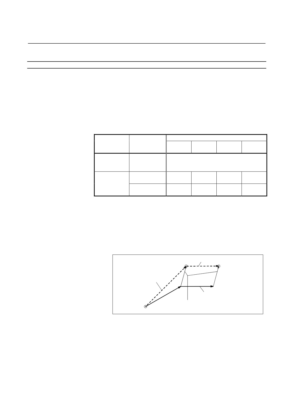
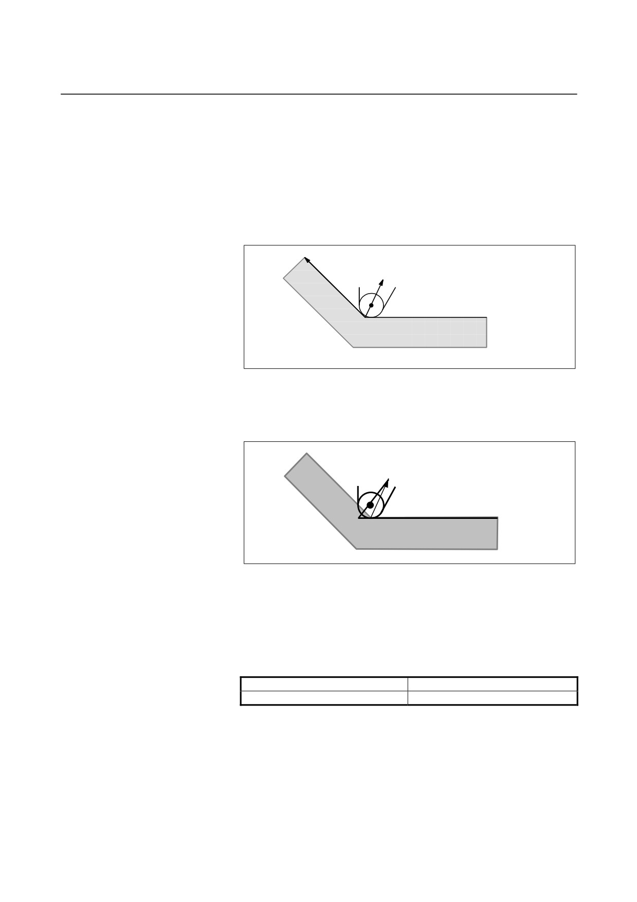
- Offset with tool movement
The tool path is offset by the X, Y, and Z tool offset values for the
programmed path. The tool offset distance corresponding to the
number specified by the T code is added to or subtracted from the end
position of each programmed block.
The vector with tool offset X, Y, and Z is called the offset vector.
Offset is the same as the offset vector.
Tool path after offset
This move command block
contains the offset command
with T code
Programmed path
Offset by tool offset X, Z (offset vector)
Offset operation with tool movement
- 164 -
B-64304EN-1/01
PROGRAMMING
5.COMPENSATION FUNCTION
NOTE
1 When G50 X_Z_T_ ; is specified, the tool is not
moved.
The coordinate system in which the coordinate
value of the tool position is (X,Z) is set. The tool
position is obtained by subtracting the offset value
corresponding to the tool offset number specified in
the T code.
2 The G codes in the 00 group other than G50 must
not be specified in the same block as that
containing a T code. If an invalid G code is
specified, alarm PS0245 is issued.
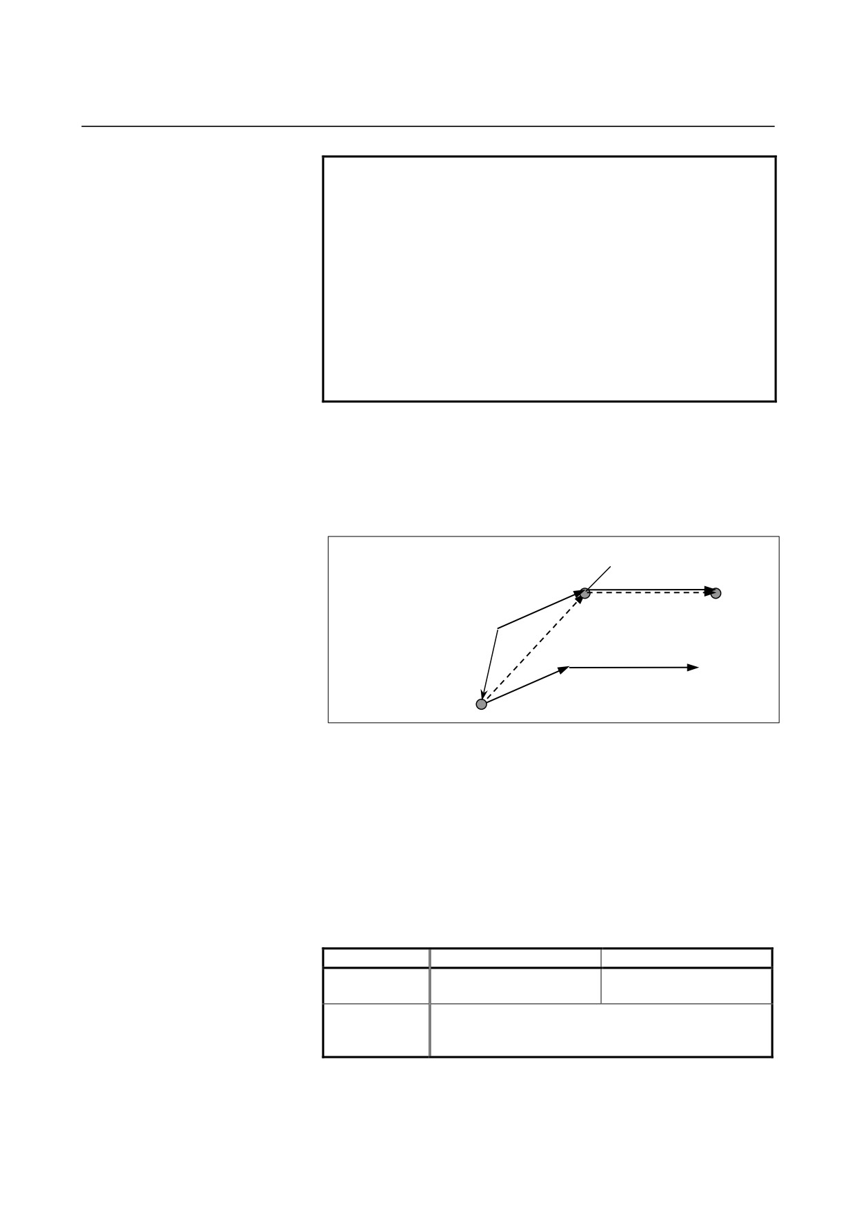
- Offset with coordinate shift
The workpiece coordinate system is shifted by the X, Y, and Z tool
offset amounts. Namely, the offset amount corresponding to the
number designated with the T code is added to or subtracted from
the absolute coordinates.
The movement to this point is
by an absolute command.
Programmed path after workpiece
coordinate system shift
Tool path after offset
Offset amount by offset in
X, Z axis (offset vector)
Programmed path before
workpiece coordinate system shift
Offset operation with coordinate shift
- Starting and canceling offset by specifying a T code
Specifying an tool offset number with a T code means to select the
tool offset value corresponding to it and to start offset. Specifying 0
as a tool offset number means to cancel offset.
For offset with tool movement, whether to start or cancel the offset
can be specified with parameter LWN
(No.
5002#6).
For
compensation with coordinate shift, the offset is started and canceled
when a T code is specified. For the cancellation of geometry
compensation, its operation can be selected with LGC (No. 5002#5).
Offset method
LWM (No.5002#6)=0
LWM (No.5002#6)=1
When an axial movement
Tool movement
When a T code is specified
is specified
When a T code is specified
Coordinate shift
(Note that geometry offset can be canceled only if LGC
(No. 5002#5) = 1.)
- 165 -
5.COMPENSATION FUNCTION
PROGRAMMING
B-64304EN-1/01
- Canceling offset with reset
Tool offset is canceled under one of the following conditions:
<1> The power to the CNC is turned off and turned back on
<2> The reset button on the MDI unit is pressed
<3> A reset signal is input from the machine to the CNC
In cases <2> and <3> above, it is possible to select a cancel operation
using parameters LVC (No. 5006#3) and TGC (No. 5003#7).
Parameter
Offset method
LVC=0
LVC=1
LVC=0
LVC=1
TGC=0
TGC=0
TGC=1
TGC=1
Wear offset
o
o
Tool
(When axial
(When axial
Geometry
x
x
movement
movement is
movement is
offset
specified)
specified)
Wear offset
x
o
x
o
Coordinate
Geometry
shift
x
x
o
o
offset
o: Canceled.
x: Not canceled.
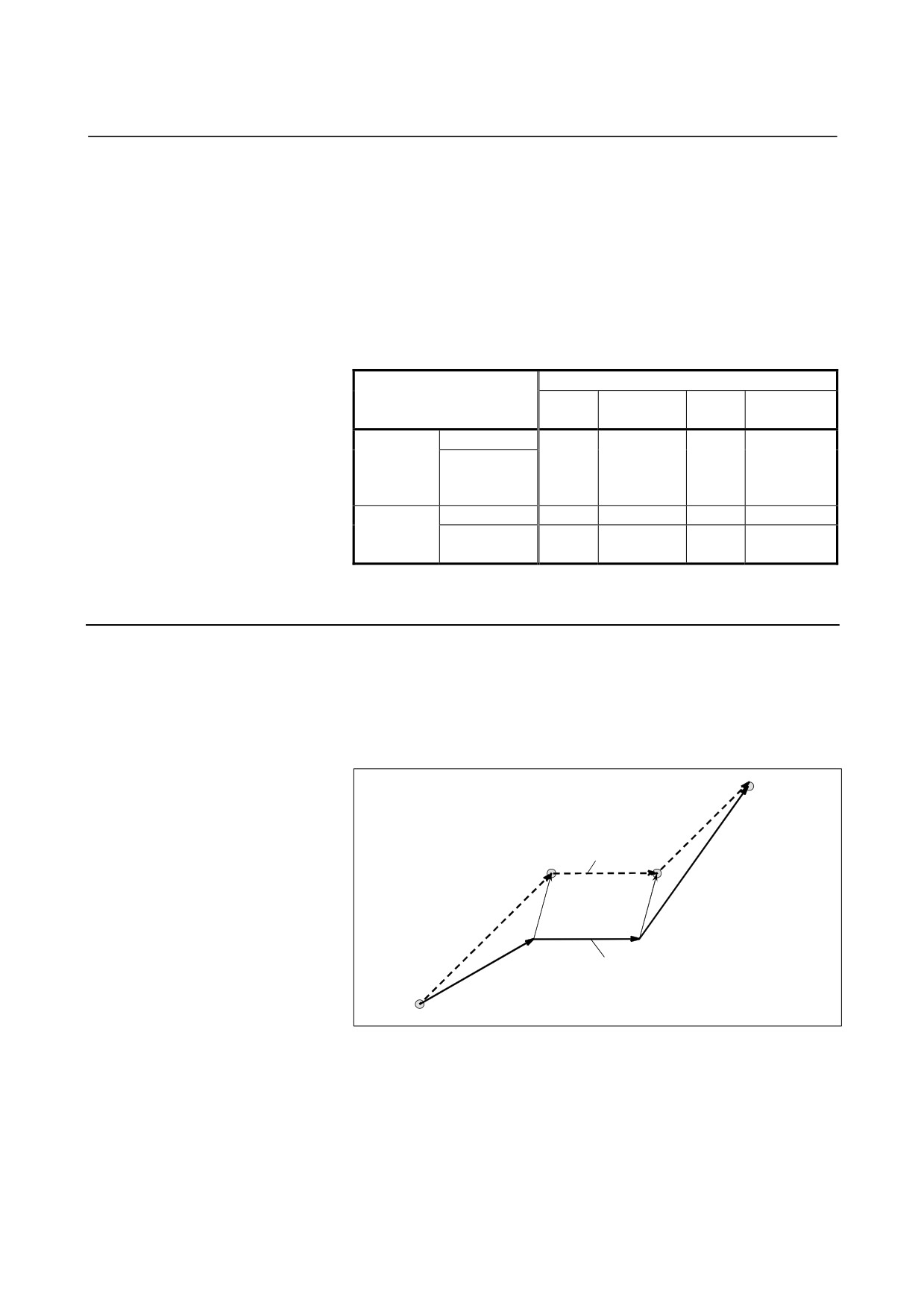
Example
N1 X60.0 Z50.0 T0202 ;
Creates the offset vector corresponding to
tool offset number 02.
N2 Z100.0 ;
N3 X200.0 Z150.0 T0200 ; Cancels the offset vector with offset number
0.
Tool path after offset
N3
N2
Programmed tool path
N1
- 166 -
B-64304EN-1/01
PROGRAMMING
5.COMPENSATION FUNCTION
Limitation
- Helical interpolation (G02, G03)
Tool offset cannot be specified in a block in which helical
interpolation is used.
- Workpiece coordinate system preset (G50.3)
Performing workpiece coordinate system preset causes tool offset with
tool movement to be canceled; this does not cause tool offset with
coordinate shift to be canceled.
-Machine coordinate system setting (G53), reference position return (G28), second,
third, and fourth reference position return (G30), and manual reference position
return
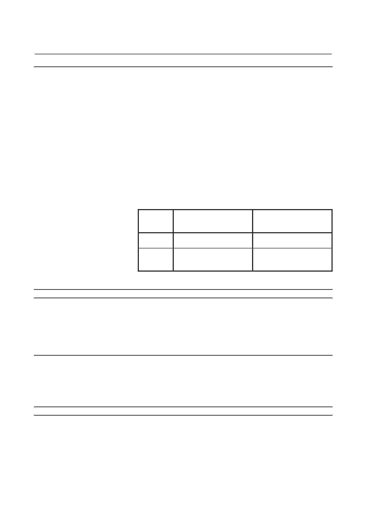
Basically, before performing these commands or operations, cancel
tool offset. These operations do not cause tool offset to be canceled.
The following actions take place:
When the next axial
When the command or
movement command is
operation is specified
specified
Tool
The tool offset value is
The tool offset value is
movement
temporarily canceled.
reflected.
Coordinate
Coordinates with the tool
Coordinates with the tool
shift
offset value reflected are
offset value reflected are
assumed.
assumed.
5.1.6
Y Axis Offset
Overview
When the Y axis, one of the basic three axes, is used with a lathe
system, this function performs Y axis offset.
When tool geometry and wear compensation is enabled (bit 6 (NGW)
of parameter No. 8136 is set to 0), the compensation is also enabled
for the Y axis offset.
Explanation
Y axis offset results in the same operation as tool offset. For an
explanation of the operation, related parameters, and the like, refer to
the item “Tool Offset.”
5.1.6.1 Y axis offset (arbitrary axes)
Overview
In a lath system, Y axis offset has been usable with the basic three
axes only. This function enables Y axis offset to be used with
arbitrary axes other than the Y axis, which is one of the basic three
axes. Specify an axis number for which to use Y axis offset for
parameter No. 5043.
- 167 -
5.COMPENSATION FUNCTION
PROGRAMMING
B-64304EN-1/01
5.2
OVERVIEW OF TOOL NOSE RADIUS COMPENSATION
(G40-G42)
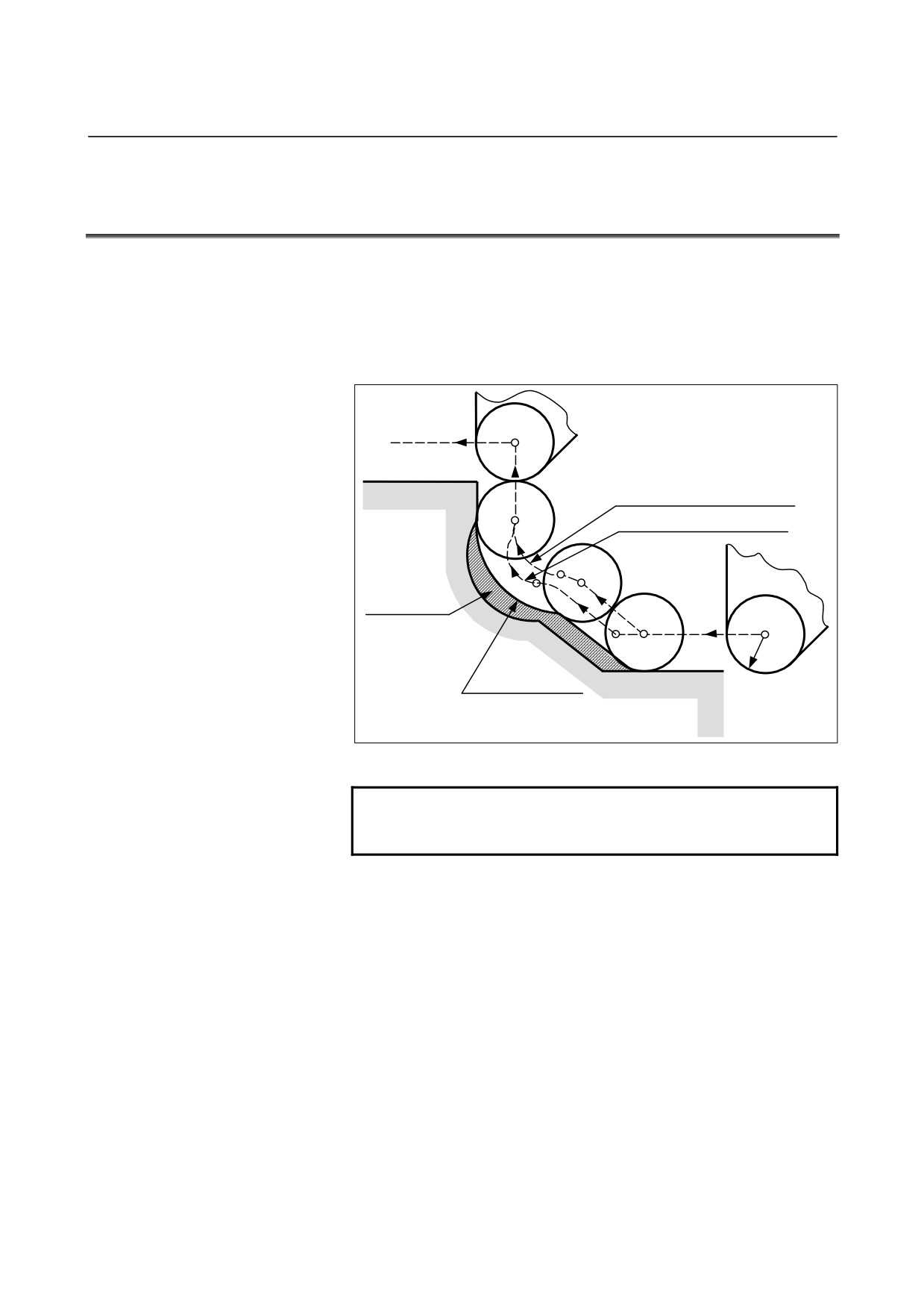
It is difficult to produce the compensation necessary to form accurate
parts when using only the tool offset function due to tool nose
roundness in taper cutting or circular cutting. The tool nose radius
compensation function compensates automatically for the above
errors.
Workpiece
Tool path without compensation
Tool path with compensation
Insufficient
Tool nose
depth of
cutting
R
Shape processed without tool
nose radius compensation
Fig 5.2 (a) Tool path of tool nose radius compensation
NOTE
To use tool nose radius compensation, set bit 7
(NCR) of parameter No. 8136 to 0.
- 168 -
B-64304EN-1/01
PROGRAMMING
5.COMPENSATION FUNCTION
5.2.1
Imaginary Tool Nose
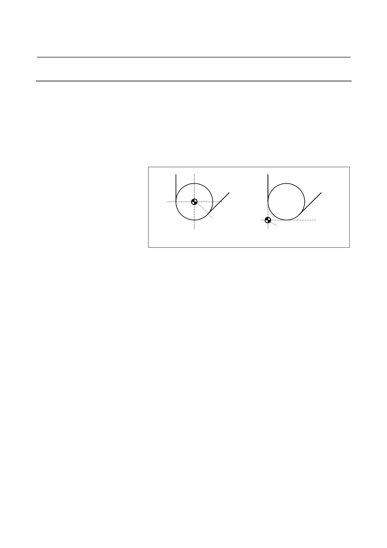
The tool nose at position A in Fig. 5.2.1 (a) does not actually exist.
The imaginary tool nose is required because it is usually more difficult
to set the actual tool nose radius center to the start point than the
imaginary tool nose.
Also when imaginary tool nose is used, the tool nose radius need not
be considered in programming.
The position relationship when the tool is set to the start point is
shown in Fig. 5.2.1 (a).
A
Start point
Start point
When programmed using the tool
When programmed using the
nose center
imaginary tool nose
Fig. 5.2.1 (a) Tool nose radius center and imaginary tool nose
- 169 -
5.COMPENSATION FUNCTION
PROGRAMMING
B-64304EN-1/01
CAUTION
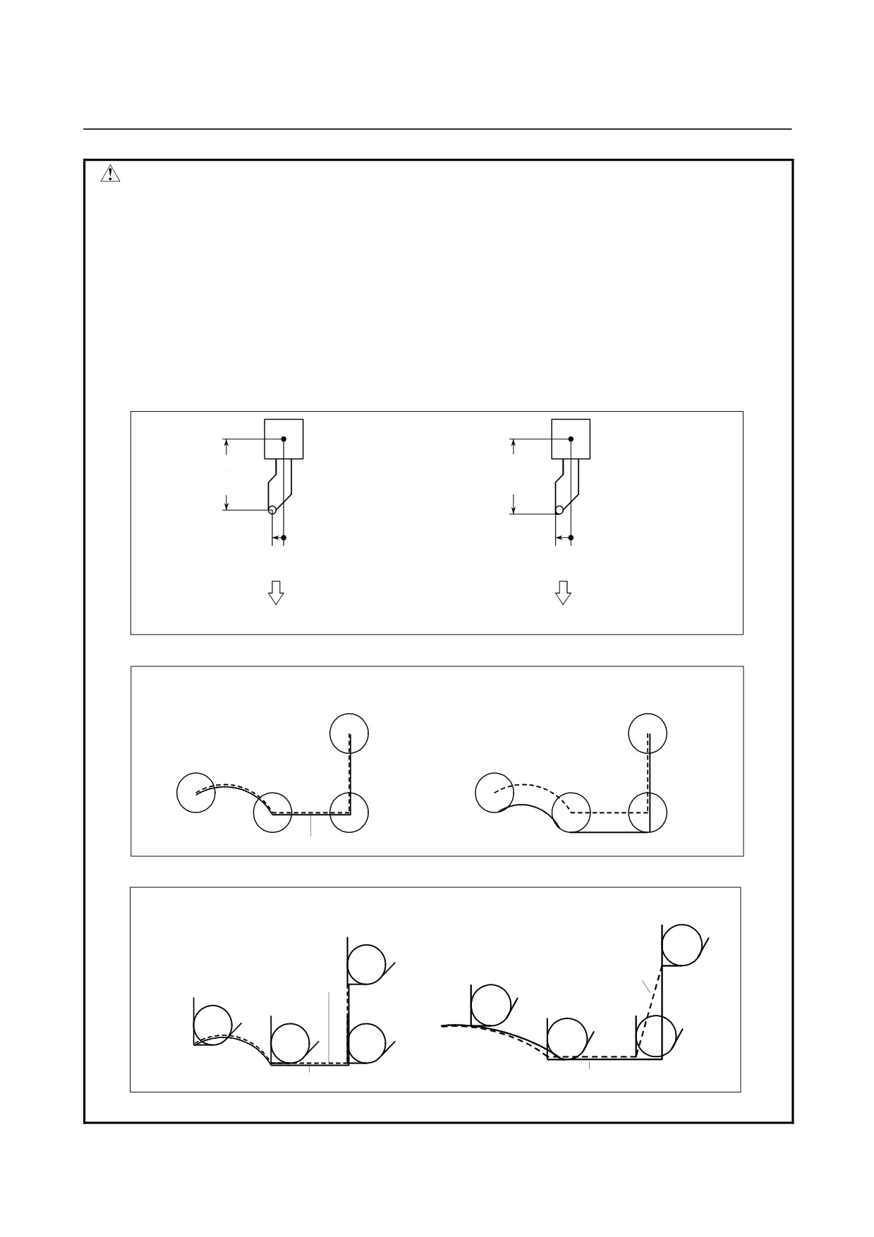
In a machine with reference positions, a standard position like the turret center can
be placed over the start point. The distance from this standard position to the
nose radius center or the imaginary tool nose is set as the tool offset value.
Setting the distance from the standard position to the tool nose radius center as the
offset value is the same as placing the tool nose radius center over the start point,
while setting the distance from the standard position to the imaginary tool nose is
the same as placing the imaginary tool nose over the standard position. To set
the offset value, it is usually easier to measure the distance from the standard
position to the imaginary tool nose than from the standard position to the tool nose
radius center.
OFX
OFX
(Tool
offset
(Tool
offset
in X axis)
in X axis)
OFZ
OFZ
(Tool offset
(Tool offset
in Z axis)
in Z axis)
Setting the distance from the standard position
Setting the distance from the standard position to
to the tool nose center as the tool offset value
the imaginary tool nose center as the tool offset
value
The start position is placed over the tool nose center
The start position is placed over the imaginary tool
nose
Fig. 5.2.1 (b) Tool offset value when the turret center is placed over the start point
Unless tool nose radius compensation is
If tool nose radius compensation is used, accurate
performed, the tool nose center path is the
cutting will be performed.
same as the programmed path.
Start-
Start-
Tool nose center path
Tool nose center path
up
up
Programmed path
Programmed path
Fig. 5.2.1 (c) Tool path when programming using the tool nose center
Without tool nose radius compensation, the
With tool nose radius compensation, accurate
tool nose radius center path is the same as
cutting will be performed.
the programmed path.
Imaginary tool
Imaginary tool
nose path
nose path
Start-
Start-
up
up
Programmed path
Programmed path
Fig. 5.2.1 (d) Tool path when programming using the imaginary tool nose
- 170 -
B-64304EN-1/01
PROGRAMMING
5.COMPENSATION FUNCTION
5.2.2
Direction of Imaginary Tool Nose
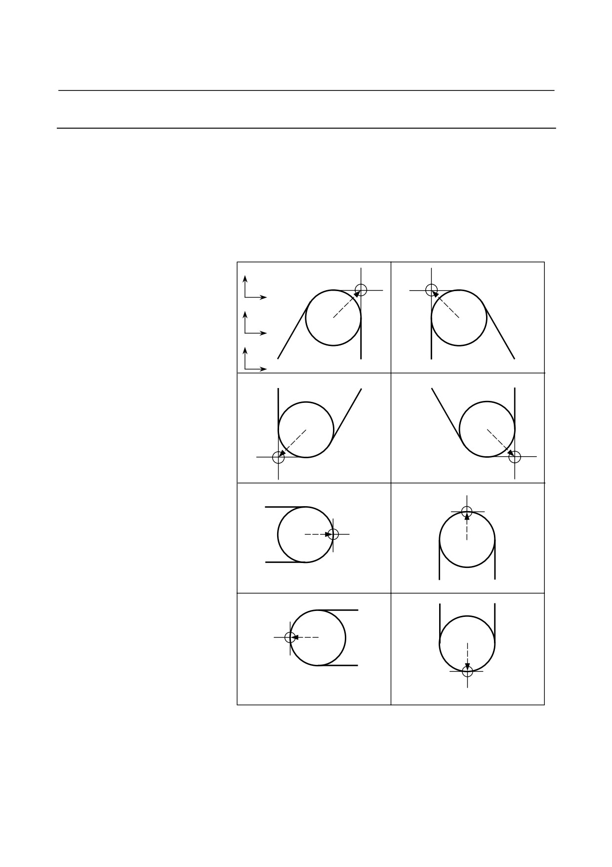
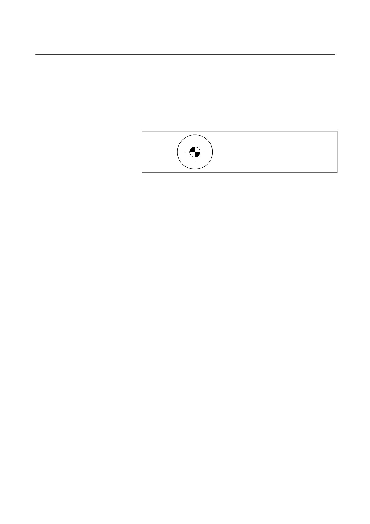
The direction of the imaginary tool nose viewed from the tool nose
center is determined by the direction of the tool during cutting, so it
must be set in advance as well as offset values.
The direction of the imaginary tool nose can be selected from the eight
specifications shown in the Fig. 5.2.2 (a) below together with their
corresponding codes. This Fig
5.2.2
(a) illustrates the relation
between the tool and the start point. The following apply when the
tool geometry offset and tool wear offset option are selected.
X
G18
Z
Y
G17
X
Z
G19
Y
Imaginary tool nose number 1
Imaginary tool nose number 2
Imaginary tool nose
Imaginary tool nose
number 3
number 4
Imaginary tool nose number 5
Imaginary tool nose number 6
Imaginary tool nose number 7
Imaginary tool nose number 8
Fig. 5.2.2 (a) Direction of imaginary tool nose
- 171 -
5.COMPENSATION FUNCTION
PROGRAMMING
B-64304EN-1/01
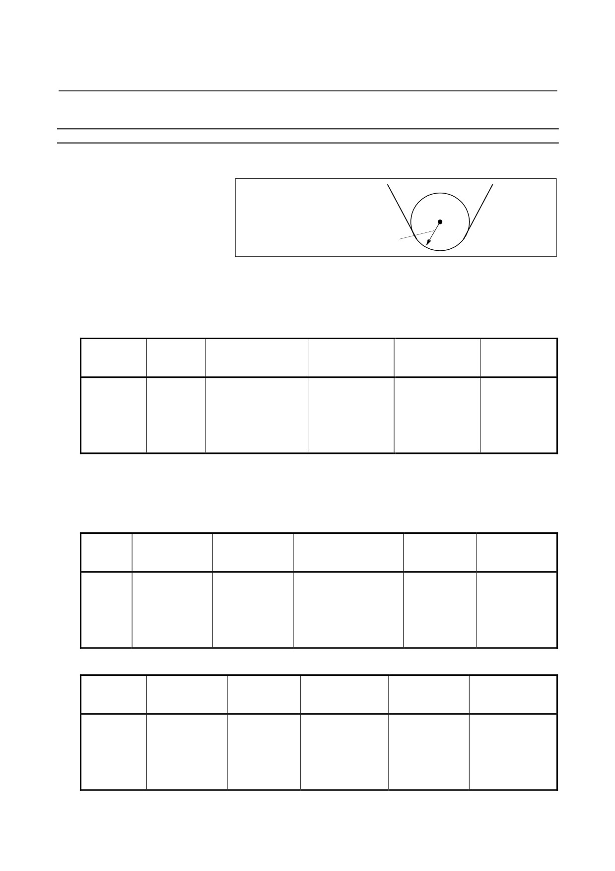
Imaginary tool nose numbers 0 and 9 are used when the tool nose
center coincides with the start point. Set imaginary tool nose number
to address OFT for each offset number.
Bit 7 (WNP) of parameter No. 5002 is used to determine whether the
tool geometry offset number or the tool wear offset number specifies
the direction of the virtual tool nose for tool nose radius
compensation.
Imaginary tool nose number 0 or 9
- 172 -
B-64304EN-1/01
PROGRAMMING
5.COMPENSATION FUNCTION
5.2.3
Offset Number and Offset Value
Explanation
- Offset number and offset value
Tool nose radius compensation value
(Tool nose radius value)
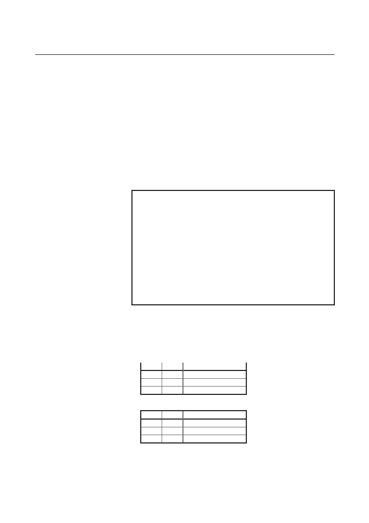
When tool geometry and wear compensation is disabled (bit 6 (NGW)
of parameter No. 8136 is set to 1), the following numbers and values
are used:
Table 5.2.3 (a) Offset number and offset value (example)
Offset
OFX (Offset
OFZ (Offset value on
OFR (Tool nose
OFT (Direction of
OFY (Offset
number Up
value on X
Z axis)
radius compensa-
imaginary tool
value on Y axis)
to 999 sets
axis)
tion value)
nose)
001
0.040
0.020
0.200
1
0.030
002
0.060
0.030
0.250
2
0.040
003
0.050
0.015
0.120
6
0.025
004
:
:
:
:
:
005
:
:
:
:
:
:
:
:
:
:
:
When tool geometry and wear compensation is enabled (bit 6 (NGW)
of parameter No. 8136 is set to 0), the following numbers and values
are used:
Table 5.2.3 (b) Tool geometry offset (example)
Geometry
OFGX
OFGZ
OFGR
OFT
OFGY
offset
(X-axis geometry
(Z-axis geometry
(Tool nose radius
(Imaginary tool
(Y-axis geometry
number
offset amount)
offset amount)
geometry offset value)
nose direction)
offset amount)
G001
10.040
50.020
0
1
70.020
G002
20.060
30.030
0
2
90.030
G003
0
0
0.200
6
0
G004
:
:
:
:
:
G005
:
:
:
:
:
:
:
:
:
:
:
Table 5.2.3 (c) Tool geometry offset (example)
OFWX (X-axis
OFWZ
OFWR
OFT (Imaginary
OFWY
Wear offset
wear offset
(Z-axis wear
(Tool nose radius
tool nose
(Y-axis wear
number
amount)
offset amount)
wear offset value)
direction)
offset amount)
W001
0.040
0.020
0
1
0.010
W002
0.060
0.030
0
2
0.020
W003
0
0
0.200
6
0
W004
:
:
:
:
:
W005
:
:
:
:
:
:
:
:
:
:
:
- 173 -
5.COMPENSATION FUNCTION
PROGRAMMING
B-64304EN-1/01
- Tool nose radius compensation
When tool geometry and wear compensation is enabled (bit 6 (NGW)
of parameter No. 8136 is set to 0), the total of the geometry and wear
offset amounts is used as the tool nose radius compensation value
during execution.
OFR=OFGR+OFWR
- Imaginary tool nose direction
The imaginary tool nose direction is common to geometry and wear
offsets.
- Command of offset value
A offset number is specified with the same T code as that used for tool
offset.
NOTE
When the geometry offset number is made common to
the tool selection by the parameter LGN (No.5002#1)
setting and a T code for which the geometry offset and
wear offset number differ from each other is
designated, the imaginary tool nose direction specified
by the geometry offset number is valid.
Example) T0102
OFR=OFGR01+OFWR02
OFT=OFT01
By setting parameter WNP (No. 5002#7) appropriately,
the imaginary tool nose direction specified with the
wear offset number can be made valid.
- Setting range of offset value
The range of values that can be set as a compensation value is either
of the following, depending on the bits 1 (OFC) and 0 (OFA) of
parameter No. 5042).
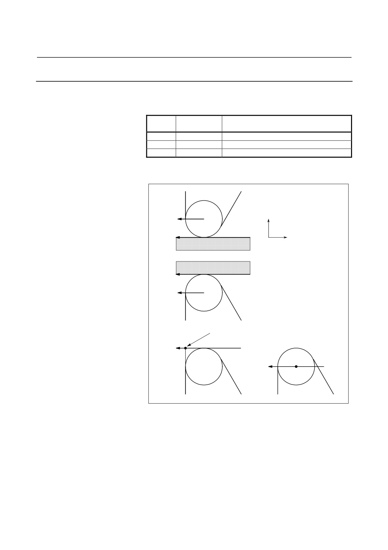
Valid compensation range (metric input)
OFC
OFA
Range
0
1
±9999.99mm
0
0
±9999.999mm
1
0
±9999.9999mm
Valid compensation range (inch input)
OFC
OFA
Range
0
1
±999.999inch
0
0
±999.9999inch
1
0
±999.99999inch
The offset value corresponding to the offset number 0 is always 0.
No offset value can be set to offset number 0.
- 174 -
B-64304EN-1/01
PROGRAMMING
5.COMPENSATION FUNCTION
5.2.4
Workpiece Position and Move Command
In tool nose radius compensation, the position of the workpiece with
respect to the tool must be specified.
Workpiece
G code
Tool path
position
G40
(Cancel)
Moving along the programmed path
G41
Right side
Moving on the left side the programmed path
G42
Left side
Moving on the right side the programmed path
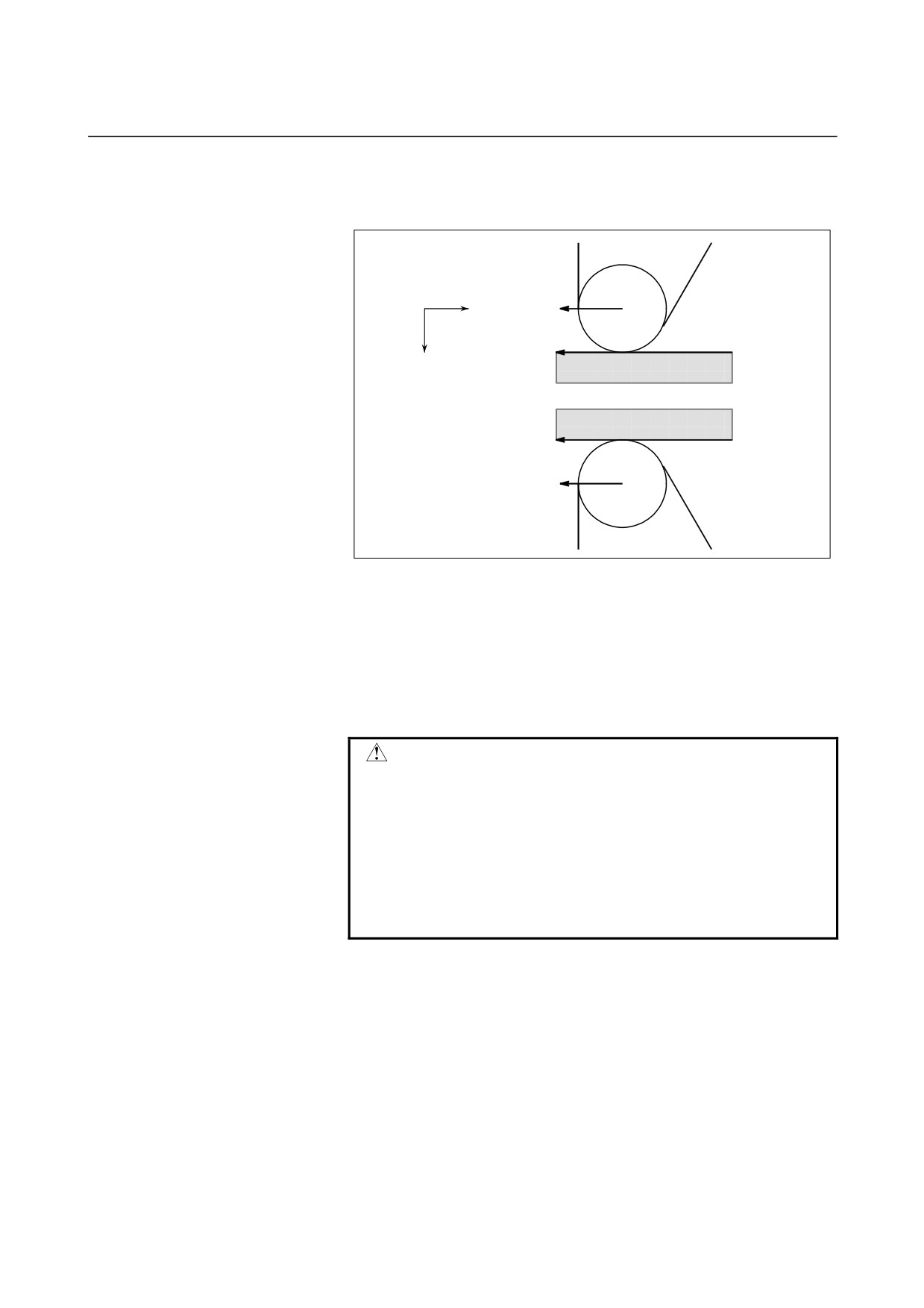
The tool is offset to the opposite side of the workpiece.
X axis
G42
Z axis
Workpiece
G41
The imaginary tool nose is on the
programmed path.
G40
G40
Imaginary tool nose
Imaginary tool nose
number 1 to 8
number 0
Fig. 5.2.4 (a) Workpiece position
- 175 -
5.COMPENSATION FUNCTION
PROGRAMMING
B-64304EN-1/01
The workpiece position can be changed by setting the coordinate
system as shown below.
Z axis
G41 (the workpiece is on
the left side)
X axis
Workpiece
G42 (the workpiece is on
NOTE
the right side)
If the tool nose radius
compensation value is negative,
the workpiece position is changed.
Fig. 5.2.4 (b) When the workpiece position is changed
G40, G41, and, G42 are modal.
Don't specify G41 while in the G41 mode. If you do, compensation
will not work properly.
Don't specify G42 while in the G42 mode for the same reason.
G41 or G42 mode blocks in which G41 or G42 are not specified are
expressed by (G41) or (G42) respectively.
CAUTION
If the sign of the compensation value is changed
from plus to minus and vice versa, the offset vector
of tool nose radius compensation is reversed, but
the direction of the imaginary tool tip does not
change. For a use in which the imaginary tool tip
is adjusted to the starting point, therefore, do not
change the sign of the compensation value for the
assumed program.
- 176 -
B-64304EN-1/01
PROGRAMMING
5.COMPENSATION FUNCTION
Explanation
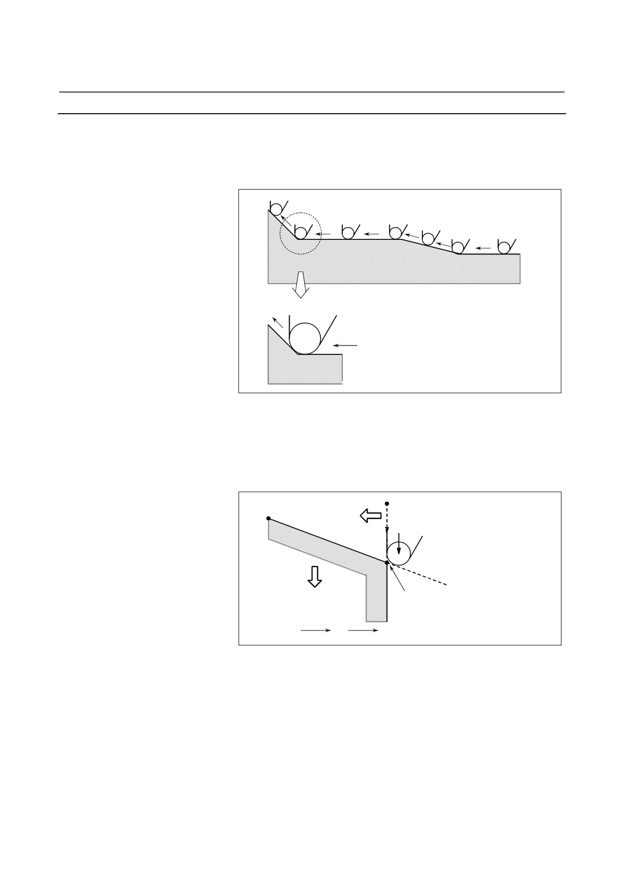
- Tool movement when the workpiece position does not change
When the tool is moving, the tool nose maintains contact with the
workpiece.
(G42)
(G42)
(G42)
(G42)
(G42)
(G42)
Enlarged
diagram
Fig. 5.2.4 (c) Tool movement when the workpiece position
does not change
- Tool movement when the workpiece position changes
The workpiece position against the tool changes at the corner of the
programmed path as shown in the following figure.
A
C
Workpiece
G41
position
G42
Workpiece
B
position
A
B
C
G41
G42
Fig. 5.2.4 (d) Tool movement when the workpiece position changes
Although the workpiece does not exist on the right side of the
programmed path in the above case, the existence of the workpiece is
assumed in the movement from A to B. The workpiece position
must not be changed in the block next to the start-up block. In the
above example, if the block specifying motion from A to B were the
start-up block, the tool path would not be the same as the one shown.
- 177 -
5.COMPENSATION FUNCTION
PROGRAMMING
B-64304EN-1/01
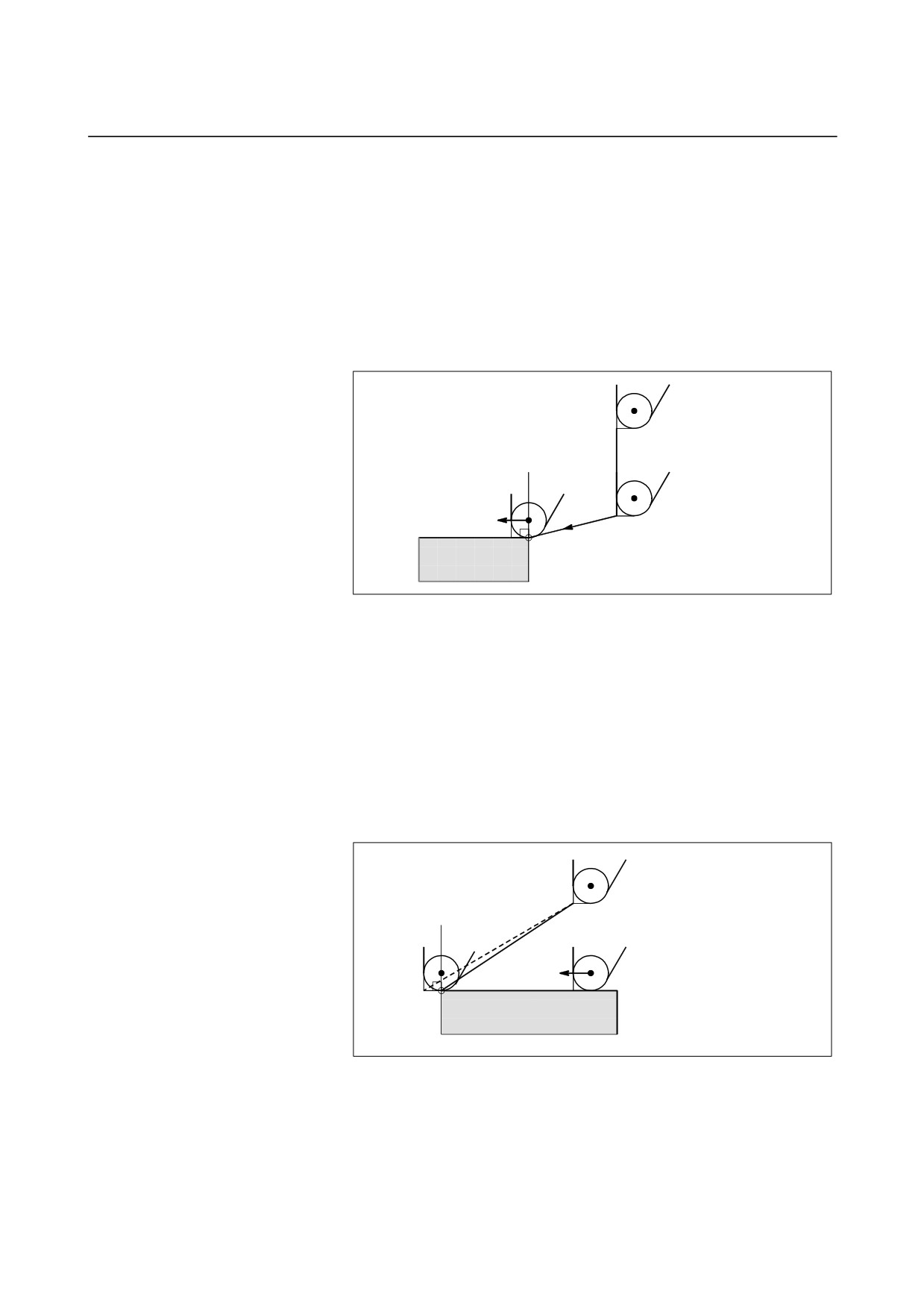
- Start-up
The block in which the mode changes to G41 or G42 from G40 is
called the start-up block.
G40 _ ;
G41 _ ; (Start-up block)
Transient tool movements for offset are performed in the start-up
block. In the block after the start-up block, the tool nose center is
positioned Vertically to the programmed path of that block at the start
point.
G40
(G42)
G42 (Start-up)
Fig. 5.2.4 (e) Start-up
- Offset cancel
The block in which the mode changes to G40 from G41 or G42 is
called the offset cancel block.
G41 _ ;
G40 _ ; (Offset cancel block)
The tool nose center moves to a position vertical to the programmed
path in the block before the cancel block.
The tool is positioned at the end position in the offset cancel block
(G40) as shown below.
End position
G40
(G42)
Fig. 5.2.4 (f) Offset cancel
- 178 -
B-64304EN-1/01
PROGRAMMING
5.COMPENSATION FUNCTION
- Changing the compensation value
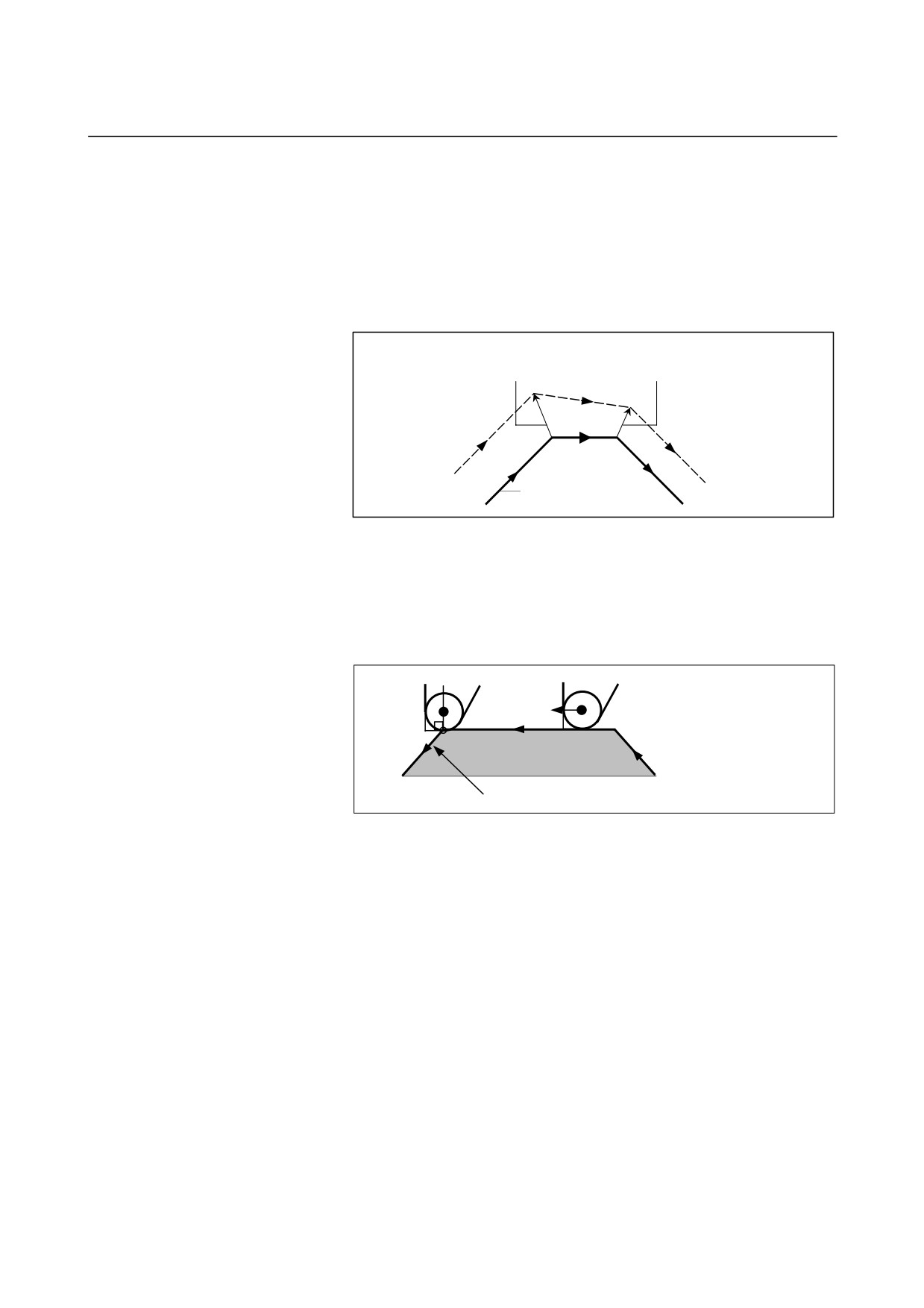
In general, the compensation value is to be changed when the tool is
changed in offset cancel mode. If the compensation value is changed
in offset mode, however, the vector at the end point of the block is
calculated using the compensation value specified in that same block.
The same applies if the imaginary tool nose direction and the tool
offset value are changed.
Calculated from the compensation
Calculated from the compensation
value specified in block N6.
value specified in block N7.
N7
N6
N8
Programmed path
Fig. 5.2.4 (g) Changing the compensation value
- Specification of G41/G42 in G41/G42 mode
When a G41 or G42 code is specified again in G41/G42 mode, the
tool nose center is positioned vertical to the programmed path of the
preceding block at the end position of the preceding block.
(G42)
(G42)
G42
G42 W-500.0 U-500.0 ;
Fig. 5.2.4 (h) Specification of G41/G42 in G41/G42 mode
In the block that first changes from G40 to G41/G42, the above
positioning of the tool nose center is not performed.
- 179 -
5.COMPENSATION FUNCTION
PROGRAMMING
B-64304EN-1/01
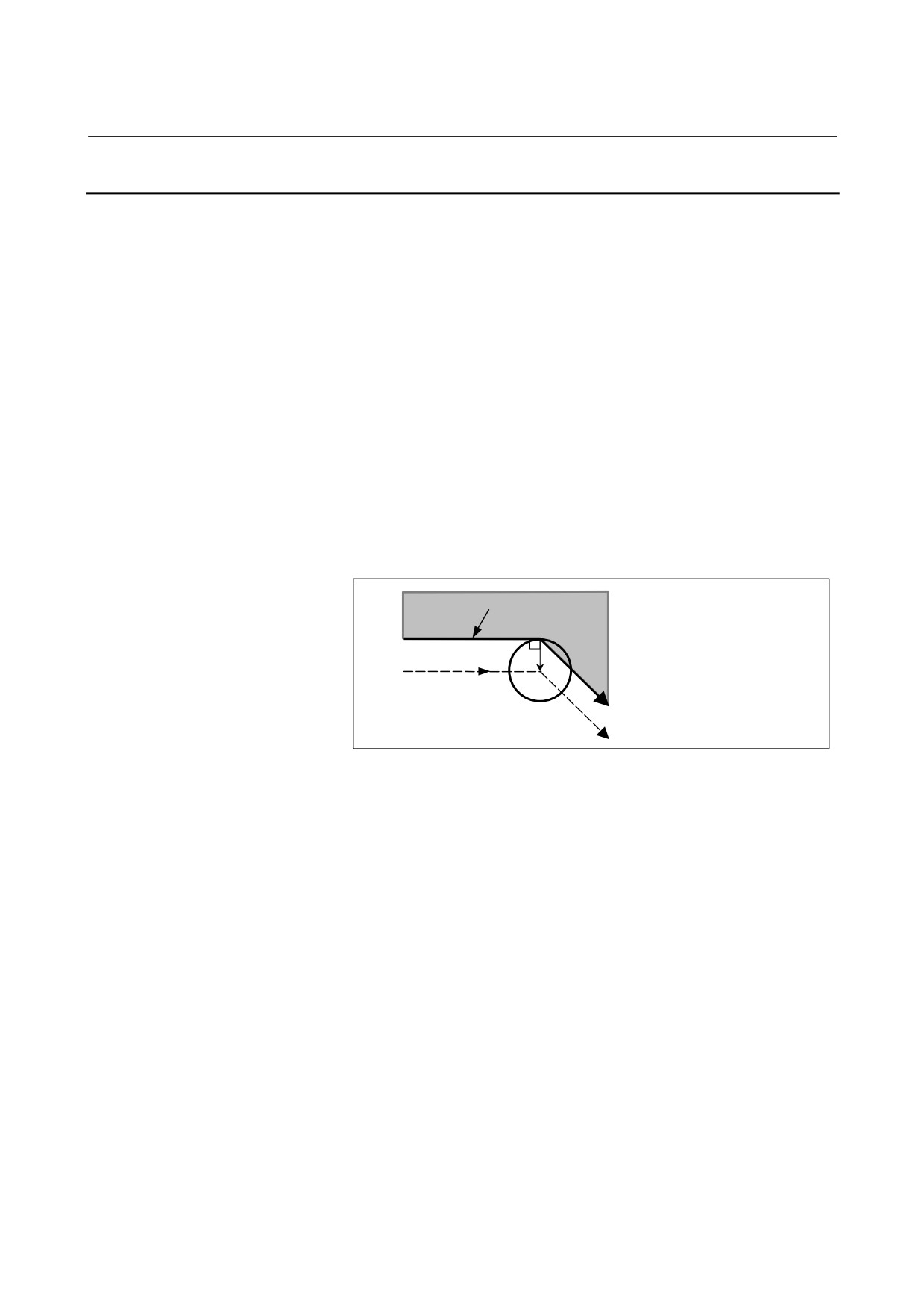
- Tool movement when the moving direction of the tool in a block which includes a
G40 (offset cancel) command is different from the direction of the workpiece
When you wish to retract the tool in the direction specified by X(U)
and Z(W) canceling the tool nose radius compensation at the end of
machining the first block in the figure below, specify the following :
G40 X(U) _ Z(W) _ I _ K _ ;
where I and K are the direction of the workpiece in the next block,
which is specified in incremental mode.
I, K
Moving direction of tool
U, W
G40
(G42)
G40 U_ W_ I_ K_ ;
Fig. 5.2.4 (i) If I and K are specified in the same block as G40
Thus, this prevents the tool from overcutting, as shown in Fig. 5.2.4
(j).
U,W
Actual move command
G40
(G42)
G40 U_ W_ ;
Fig. 5.2.4 (j) Case in which overcutting occurs in the same block as
G40
The workpiece position specified by addresses I and K is the same as
that in the preceding block.
Specify I_K_; in the same block as G40. If it is specified in the same
block as G02 or G03, it is assumed to be the center of the arc.
G40 X_ Z_ I_ K_ ;
Tool nose radius compensation
G02 X_ Z_ I_ K_ ;
Circular interpolation
If I and/or K is specified with G40 in the offset cancel mode, the I
and/or K is ignored. The numeral is followed I and K should always
be specified as radius values.
G40 G01 X_ Z_ ;
G40 G01 X_ Z_ I_ K_ ; Offset cancel mode (I and K are ineffective.)
- 180 -
B-64304EN-1/01
PROGRAMMING
5.COMPENSATION FUNCTION
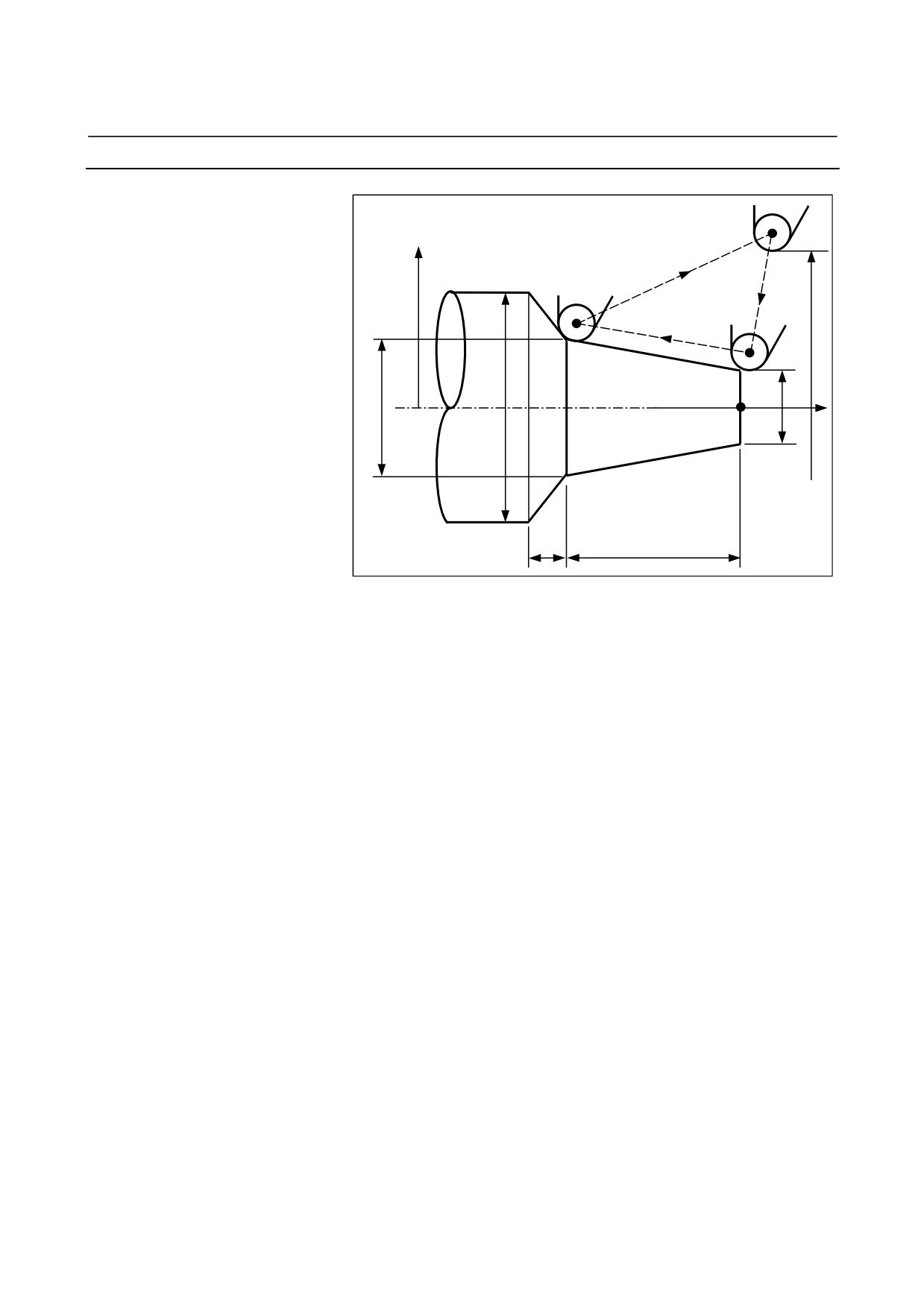
Example
X
<3>
φ300
<1>
<2>
200
φ60
Z
120
0
30
150
(G40 mode)
<1> G42 G00 X60.0 ;
<2> G01 X120.0 W-150.0 F10 ;
<3> G40 G00 X300.0 W150.0 I40.0 K-30.0 ;
- 181 -
5.COMPENSATION FUNCTION
PROGRAMMING
B-64304EN-1/01
5.2.5
Notes on Tool Nose Radius Compensation
Explanation
- Blocks without a move command that are specified in offset mode
<1> M05 ;
M code output
<2> S210 ;
S code output
<3> G04 X10.0 ;
Dwell
<4> G22 X100000 ;
Machining area setting
<5> G01 U0 ;
Feed distance of zero
<6> G98 ;
G code only
<7> G10 P01 X10.0 Z20.0 R0.5 Q2 ; Offset change
If the number of such blocks consecutively specified is more than N-2
blocks (where N is the number of blocks to read in offset mode
(parameter No. 19625)), the tool arrives at the position vertical to this
block at the end point of the previous block.
If the feed distance is 0 (<5>), this applies even if only one block is
specified.
Programmed path
(G42 mode)
N6 W100.0 ;
N6
N7
N7 S21 ;
N8
N8 M04 ;
U9 U-100.0 W100.0 ;
N9
(Number of blocks to be read
Tool nose center path
in offset mode = 3)
Overcutting may, therefore, occur in the above figure.
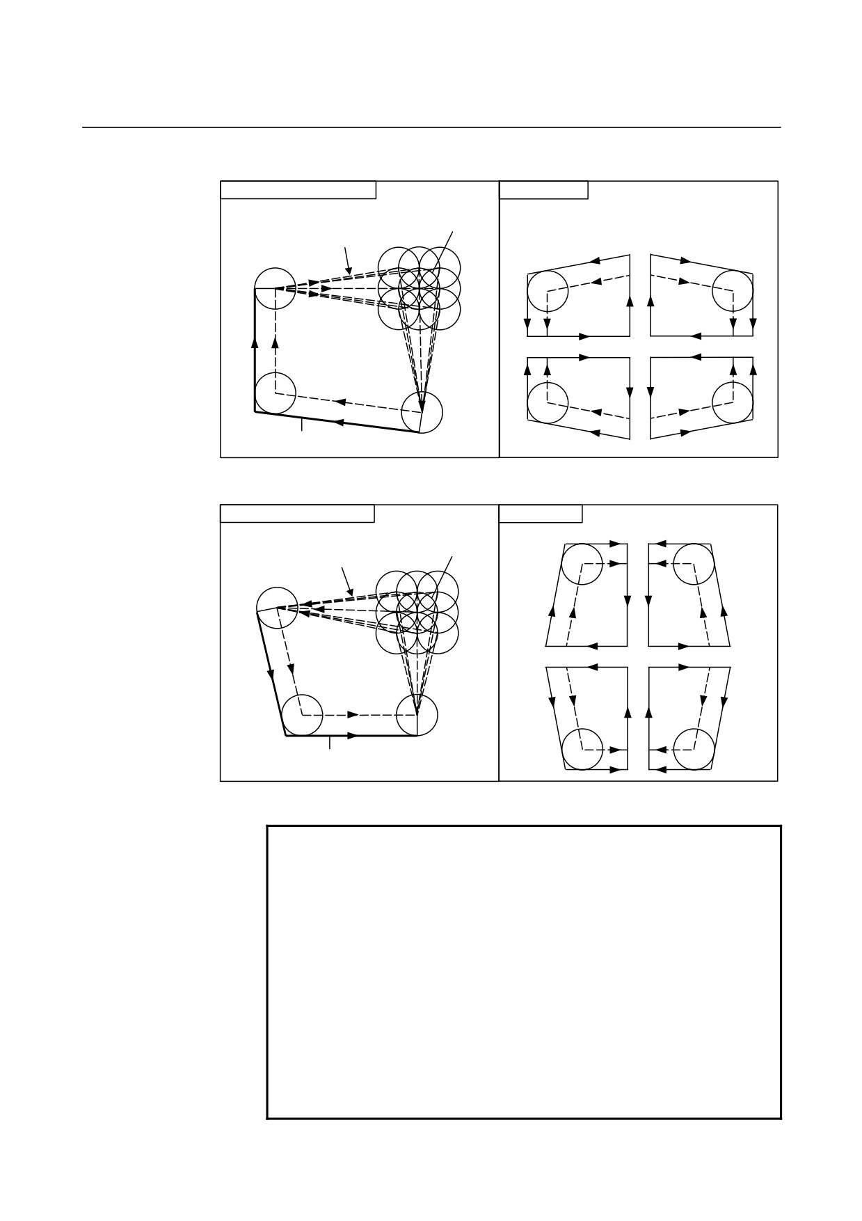
- Tool nose radius compensation with G90 or G94
The tool nose center path and the offset direction are as shown below
if tool nose radius compensation is applied. At the cycle start point,
the offset vector disappears, and offset starts up with tool movement
from the cycle start point. In addition, during a return to the cycle
start point, the offset vector disappears temporarily, and offset is
applied again with the next move command. The offset direction is
determined by the cutting pattern, regardless of G41 or G42.
- 182 -
B-64304EN-1/01
PROGRAMMING
5.COMPENSATION FUNCTION
- Outer/inner turning cycle (G90)
Tool nose radius center path
Offset direction
0
Tool nose radius
center path
8
3
Total tool nose
4
7
5
1
2
6
Total tool nose
Total tool
nose
Programmed path
- End cutting cycle (G94)
Tool nose radius center path
Offset direction
Tool nose radius
0
center path
8
4
3
Total tool nose
5
7
1
6
2
Total tool
Total tool nose
nose
Programmed path
- Difference from Series 0i-C
NOTE
The offset direction is the same as that of Series 0i-C, but
the tool nose radius center path is different.
• For this CNC
The operation is the same as that performed if the
canned cycle operation is replaced with G00 or G01,
start-up is performed in the first block for movement from
the start point, and offset cancel is performed in the last
block for returning to the start point.
• For Series 0i-C
The operation with the block for movement from the start
point and the last block for returning to the start point
differs from that of this CNC. For details, refer to the
Series 0i-C Operator's Manual.
- 183 -
5.COMPENSATION FUNCTION
PROGRAMMING
B-64304EN-1/01
- Tool nose radius compensation with G71 to G73
Tool nose radius compensation performed with G71 (outer surface
rough cutting cycle or traverse grinding cycle), G72
(end rough
cutting cycle or traverse direct constant-size grinding cycle), and G73
(closed loop cutting cycle or oscillation direct constant-size grinding
cycle), see the explanations of the respective cycles.
- Tool nose radius compensation with G74 to G76 and G92
With G74 (end cutting off cycle), G75 (outer/inner surface cutting off
cycle), G76 (multiple threading cycle), and G92 (threading cycle), tool
nose radius compensation cannot be applied.
- Tool nose radius compensation when chamfering is performed
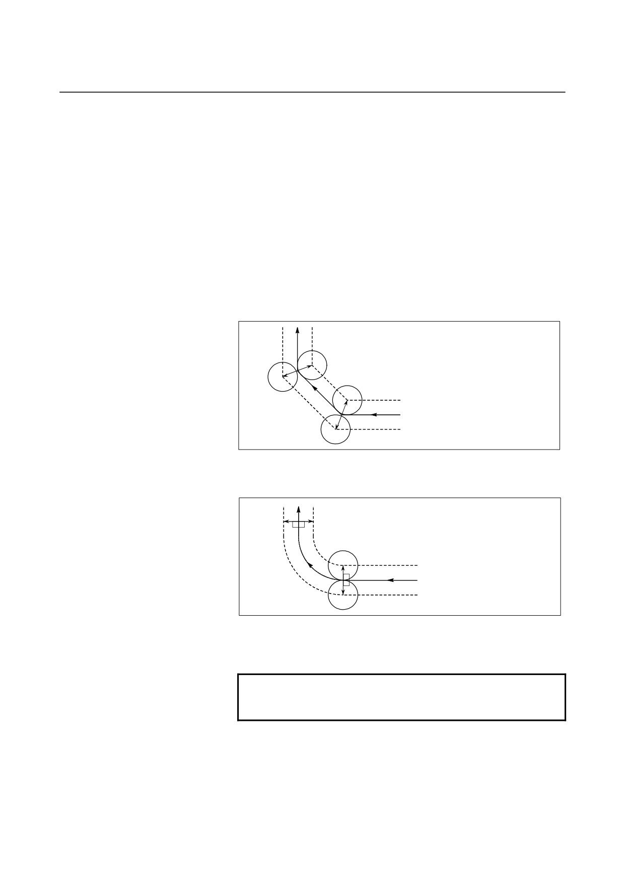
Movement after compensation is shown below.
(G42 mode)
G01 W-20.0 I10.0;
U20.0;
(G42)
Programmed path
(G41)
- Tool nose radius compensation when a corner arc is inserted
Movement after compensation is shown below.
(G42 mode)
G01 W-20.0 R10.0;
U20.0;
(G42)
Programmed path
(G41)
- Tool nose radius compensation for MDI operation.
Tool nose radius compensation is valid for MDI operation.
NOTE
For Series 0i-C, tool nose radius compensation is
invalid for MDI operation.
- 184 -
B-64304EN-1/01
PROGRAMMING
5.COMPENSATION FUNCTION
5.3
DETAILS OF TOOL NOSE RADIUS COMPENSATION
5.3.1
Overview
This subsection details tool movement in tool nose radius
compensation.
- Tool nose radius center offset vector
The tool nose radius center offset vector is a two dimensional vector
equal to the offset value specified in a T code, and the vector is
calculated in the CNC. Its dimension changes block by block
according to tool movement.
This offset vector
(simply called vector herein after) is internally
crated by the control unit as required for proper offsetting and to
calculate a tool path with exact offset (by tool nose radius) from the
programmed path.
This vector is deleted by resetting.
The vector always accompanies the tool as the tool advances.
Proper understanding of vector is essential to accurate programming.
Read the description below on how vectors are created carefully.
- G40, G41, G42
G40, G41 or G42 is used to delete or generate vectors.
These codes are used together with G00, G01, G02, or G32 to specify
a mode for tool motion (Offsetting).
G code
Workpiece position
Function
G40
Neither
Tool nose radius compensation cancel
G41
Right
Left offset along tool path
G42
Left
Right offset along tool path
G41 and G42 specify an offset mode, while G40 specifies cancellation
of the offset.
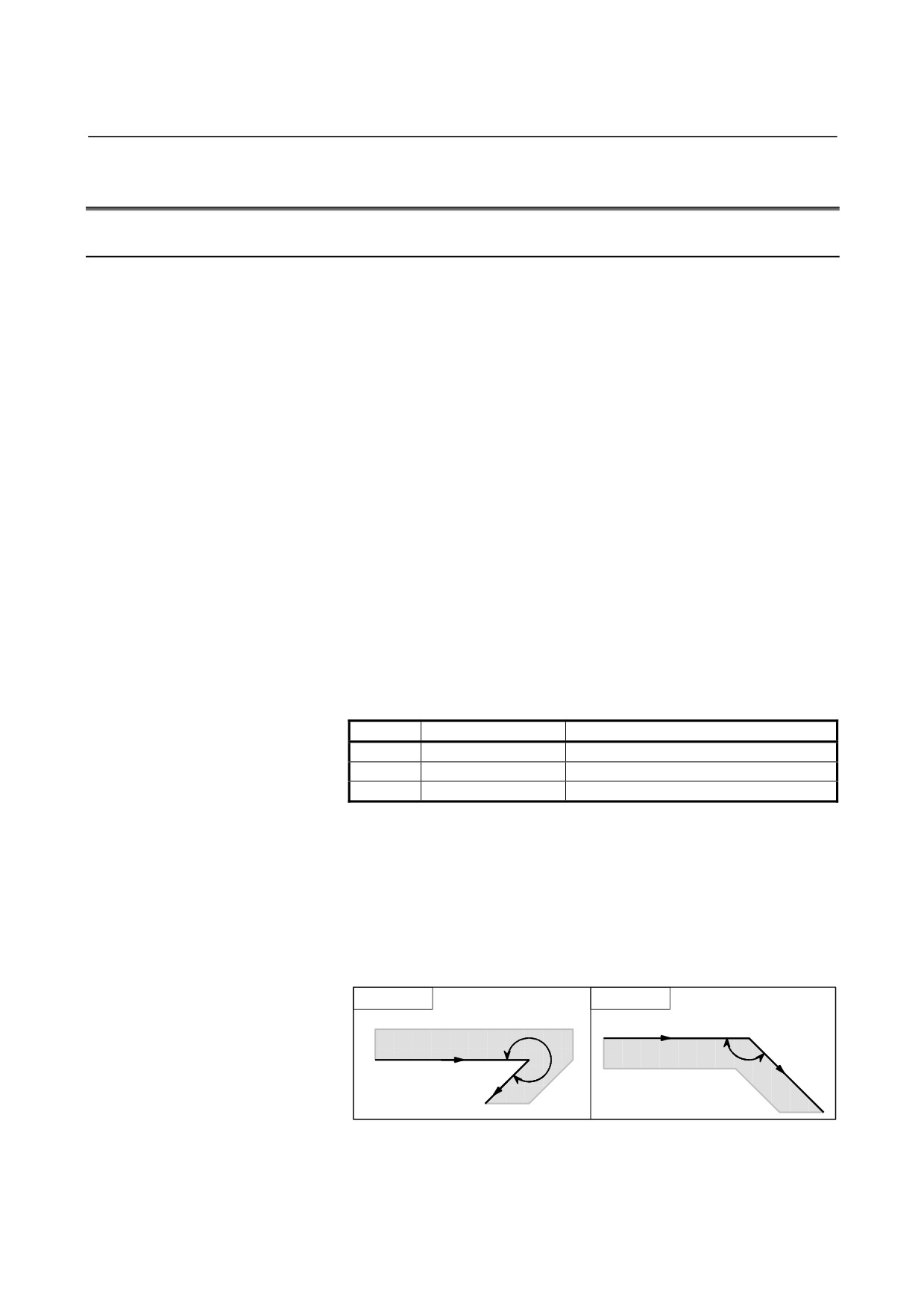
- Inner side and outer side
When an angle of intersection of the tool paths specified with move
commands for two blocks on the workpiece side is over 180°, it is
referred to as "inner side." When the angle is between 0° and 180°, it
is referred to as "outer side."
Inner side
Outer side
Programmed path
Workpiece
α
α
Workpiece
Programmed path
180°≤a
0°≤α<180°
- 185 -
5.COMPENSATION FUNCTION
PROGRAMMING
B-64304EN-1/01
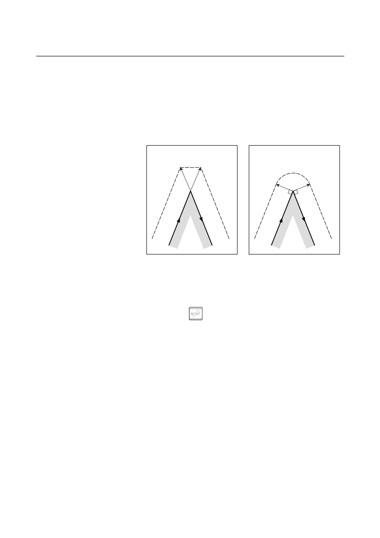
- Outer corner connection method
If the tool moves around an outer corner in tool nose radius
compensation mode, it is possible to specify whether to connect
compensation vectors with linear interpolation or with circular
interpolation, using parameter CCC (No. 19607#2).
<1> Linear connection type
<2> Circular connection type
[Parameter CCC
[Parameter CCC
(No.19607#2) = 0]
(No.19607#2) = 1]
Vectors are connected with linear
Vectors are connected with circular
interpolation.
interpolation.
- Cancel mode
The tool nose radius compensation enters the cancel mode under the
following conditions.
(The system may not enter the cancel mode
depending on the machine tool.)
<1> Immediately after the power is turned on
<2> After the
key on the MDI panel is pushed
<3> After a program is forced to end by executing M02 or M30
<4> After the tool nose radius compensation cancel command (G40)
is exercised
In the cancel mode, the magnitude of a compensation vector is 0 at all
times and the path of the virtual tool nose matches the programmed
path. A program must end in cancel mode. If it ends in the tool
nose radius compensation mode, the tool cannot be positioned at the
end point, and the tool stops at a location the compensation vector
length away from the end point.
- 186 -
B-64304EN-1/01
PROGRAMMING
5.COMPENSATION FUNCTION
NOTE
The operation performed when a reset operation is
performed during tool nose radius compensation
varies according to the setting of bit 6 (CLR) of
parameter No. 3402.
• When CLR=0
The reset state is set. The modal information
of G41/G42 in group 07 is preserved. To
perform tool nose radius compensation,
however, an offset number (T code) needs to be
specified again.
• When CLR=1
The cleared state is set. The modal
information of G40 in group 07 is preserved.
To perform tool nose radius compensation,
G41/G42 and an offset number (T code) need to
be specified.
- Start-up
When a block which satisfies all the following conditions is executed
in cancel mode, the CNC enters the offset mode. Control during this
operation is called start-up.
<1> G41 or G42 is contained in the block, or has been specified to
place the CNC in the offset mode.
<2> 0 < compensation number of tool nose radius compensation ≤
maximum compensation number
<3> Positioning (G00) or linear interpolation (G01) mode
<4> A compensation plane axis command with a travel distance of 0
(except start-up type C) is specified.
If start-up is specified in circular interpolation
(G02, G03) mode,
alarm PS0034 will occur.
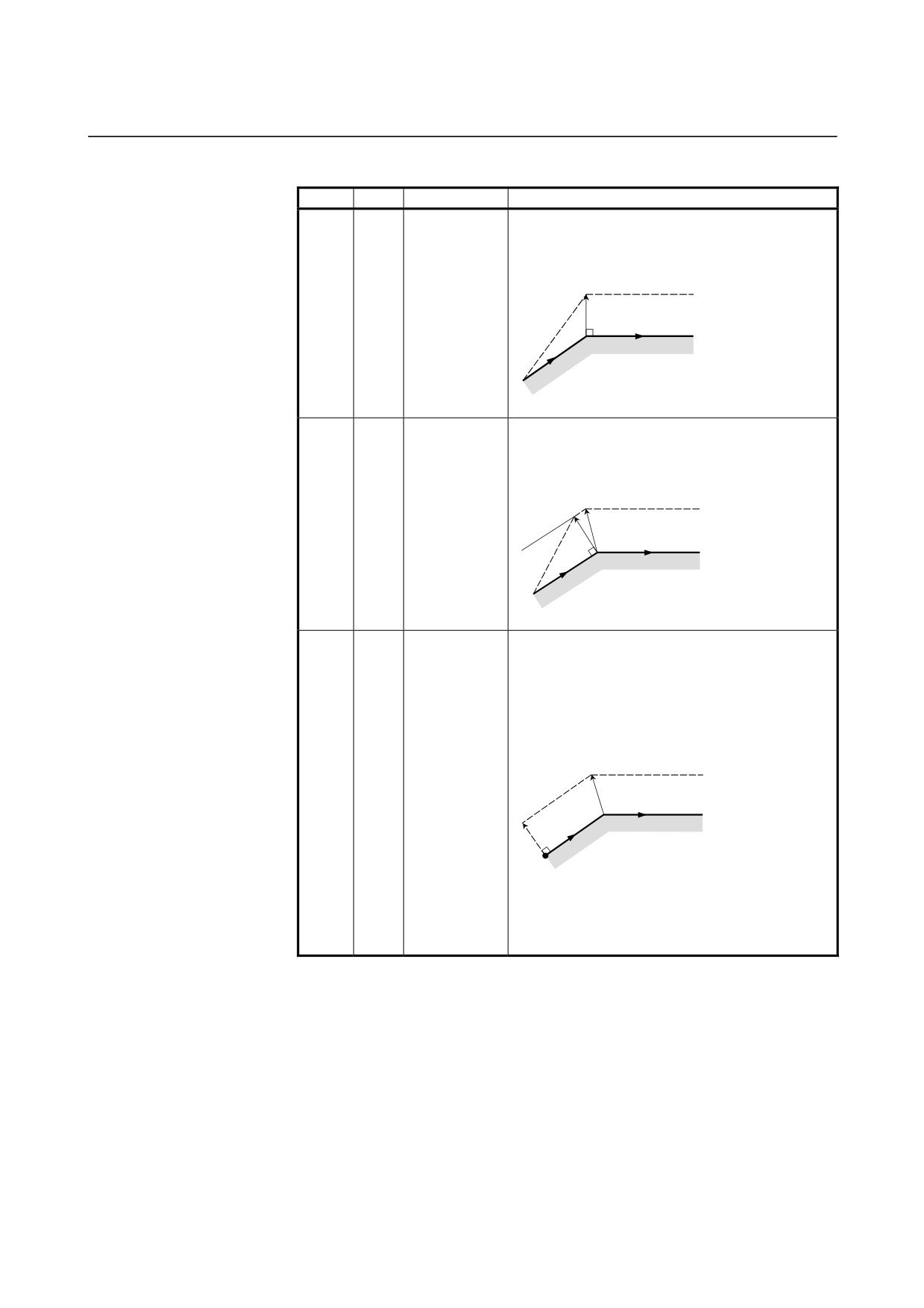
As a start-up operation, one of the three types A, B, and C can be
selected by setting bits 0 (SUP) and 1 (SUV) of parameter No. 5003
appropriately. The operation to be performed if the tool moves
around an inner side is of single type only.
- 187 -
5.COMPENSATION FUNCTION
PROGRAMMING
B-64304EN-1/01
Table 5.3.1 (a) Start-up/cancel operation
SUV
SUP
Type
Operation
0
0
Type A
A compensation vector is output, which is vertical
to the block subsequent to the start-up block and
the block preceding the cancel block.
Tool nose radius center path
G41
Programmed path
N2
N1
0
1
Type B
A compensation vector is output, which is vertical
to the start-up block and the cancel block. An
intersection vector is also output.
Intersection
Tool nose radius center path
Programmed path
G41
N2
N1
1
0
Type C
When the start-up block and the cancel block are
1
blocks without tool movement, the tool moves by
the tool nose radius compensation value in the
direction vertical to the block subsequent to the
start-up block and the block preceding the cancel
block.
Intersection
Tool nose radius center path
Programmed path
Programmed
N3
path
G41
N2
N1
For a block with tool movement, the tool follows
the SUP setting: If it is 0, type A is assumed and
if 1, type B is assumed.
- 188 -
B-64304EN-1/01
PROGRAMMING
5.COMPENSATION FUNCTION
- Reading input commands in tool nose radius compensation mode
In tool nose radius compensation mode, input commands are read
from usually three blocks and up to eight blocks depending on the
setting of parameter (No. 19625) to perform intersection calculation or
an interference check, described later, regardless of whether the blocks
are with or without tool movement, until a cancel command is
received.
To perform intersection calculation, it is necessary to read at least two
blocks with tool movement. To perform an interference check, it is
necessary to read at least three blocks with tool movement.
As the setting of parameter (No. 19625), that is, the number of blocks
to read, increases, it is possible to predict overcutting (interference)
for up to more subsequent commands. Increases in blocks to read
and analyze, however, cause reading and analysis to take more time.
- Meaning of symbols
The following symbols are used in subsequent figures:
• S indicates a position at which a single block is executed once.
• SS indicates a position at which a single block is executed twice.
• SSS indicates a position at which a single block is executed three
times.
• L indicates that the tool moves along a straight line.
• C indicates that the tool moves along an arc.
• r indicates the tool nose radius compensation value.
• An intersection is a position at which the programmed paths of two
blocks intersect with each other after they are shifted by r.
•
indicates the center of the tool nose radius.
- 189 -
5.COMPENSATION FUNCTION
PROGRAMMING
B-64304EN-1/01
5.3.2
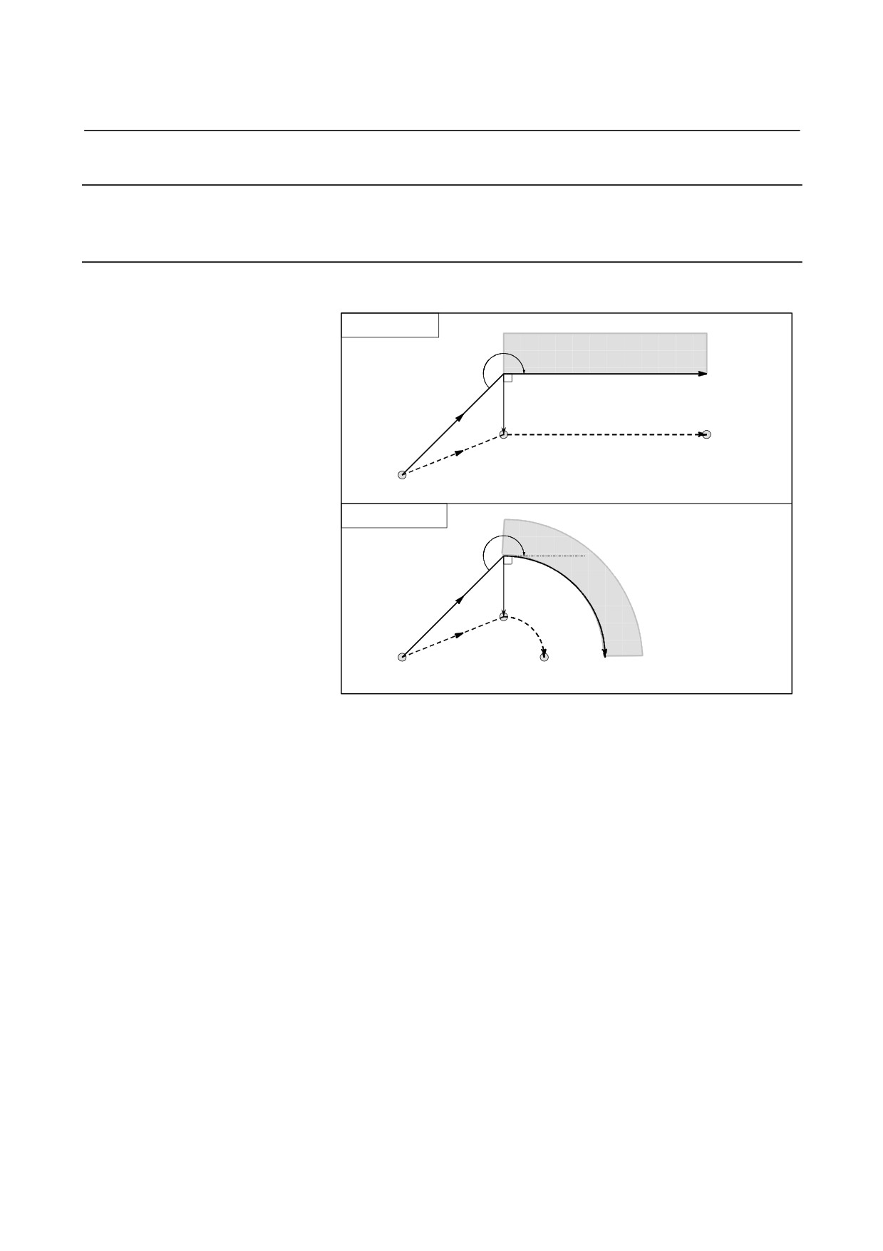
Tool Movement in Start-up
When the offset cancel mode is changed to offset mode, the tool
moves as illustrated below (start-up):
Explanation
- Tool movement around an inner side of a corner (180°≤ α)
Linear→Linear
α
Workpiece
Programmed path
r
G42
S
L
Tool nose radius center path
L
Start point
Linear→Circular
α
Work-
G42
piece
S
C
L
Start point
Tool nose radius
Programmed path
center path
- 190 -
B-64304EN-1/01
PROGRAMMING
5.COMPENSATION FUNCTION
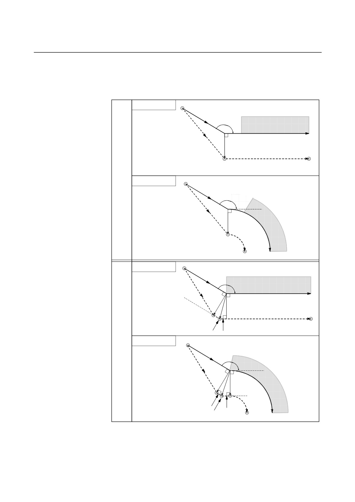
- Cases in which the start-up block is a block with tool movement and the tool
moves around the outside at an obtuse angle (90°≤ α<180°)
Tool path in start-up has two types A and B, and they are selected by
parameter SUP (No.5003#0).
Linear→Linear
Start point
G42
α
Workpiece
L
Programmed path
r
S
L
Tool nose radius
center path
Type
A
Linear→Circular
Start point
G42
α
L
r
Work-
piece
e
S
Tool nose radius center path
Programmed path
Linear→Linear
(Linear connection type)
Start point
G42
α
Workpiece
L
Programmed path
r
r
L
S
Tool nose radius
center path
Intersection
L
Type
Linear→Circular
B
Start point
(Linear connection type)
G42
α
L
r
ork-
r
ece
S
C
L
Intersection
Tool
h
Programmed path
- 191 -
5.COMPENSATION FUNCTION
PROGRAMMING
B-64304EN-1/01
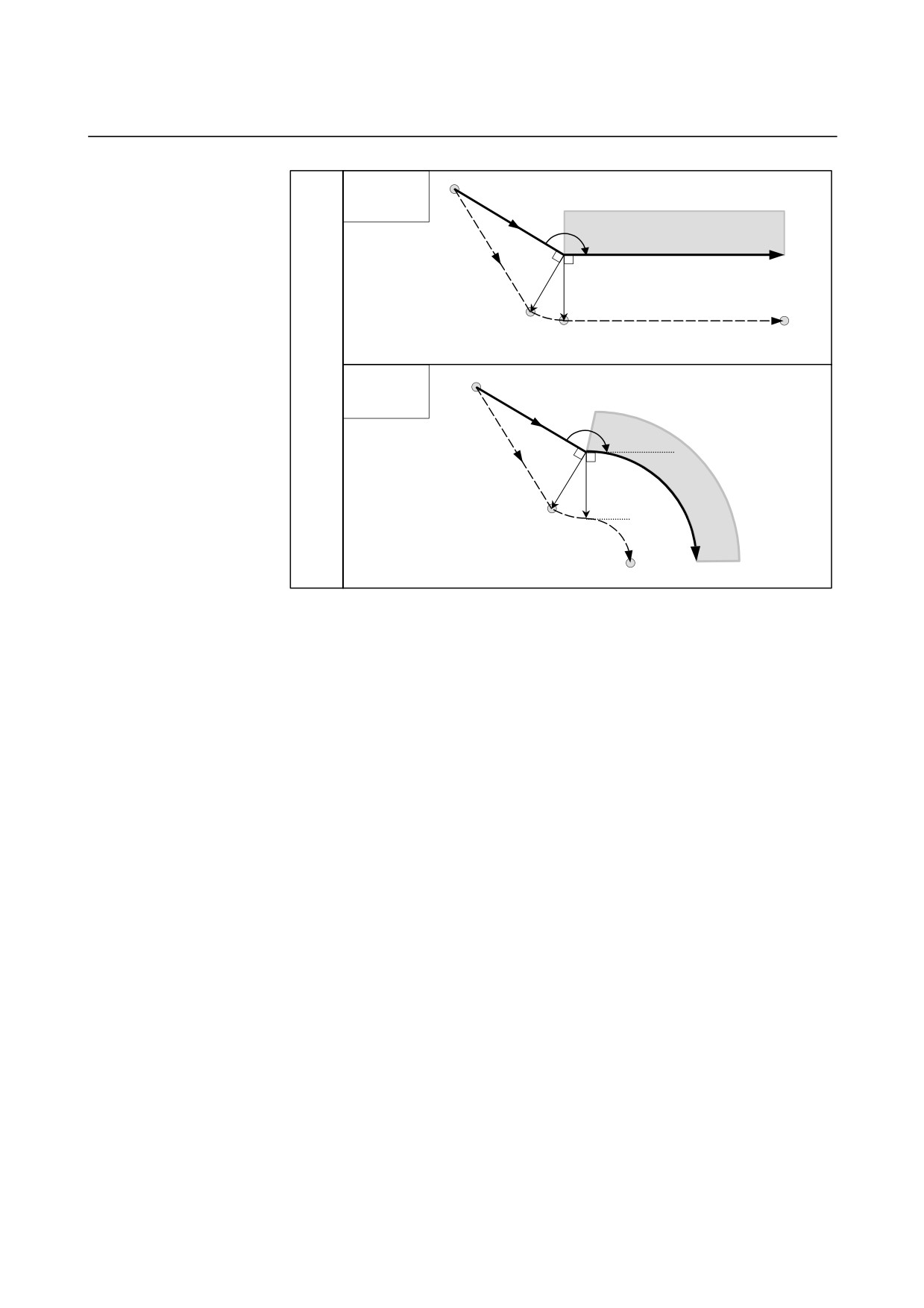
Linear→Linear
Start point
(Circular
connection type)
G42
α
Workpiece
L
Programmed path
r
r
C
L
Tool nose radius
S
center path
Type
B
Linear→Circular
Start point
(Circular
connection type)
G42
α
L
r
Workpiece
r
C
S
C
Tool nose radius center path Programmed path
- 192 -
B-64304EN-1/01
PROGRAMMING
5.COMPENSATION FUNCTION
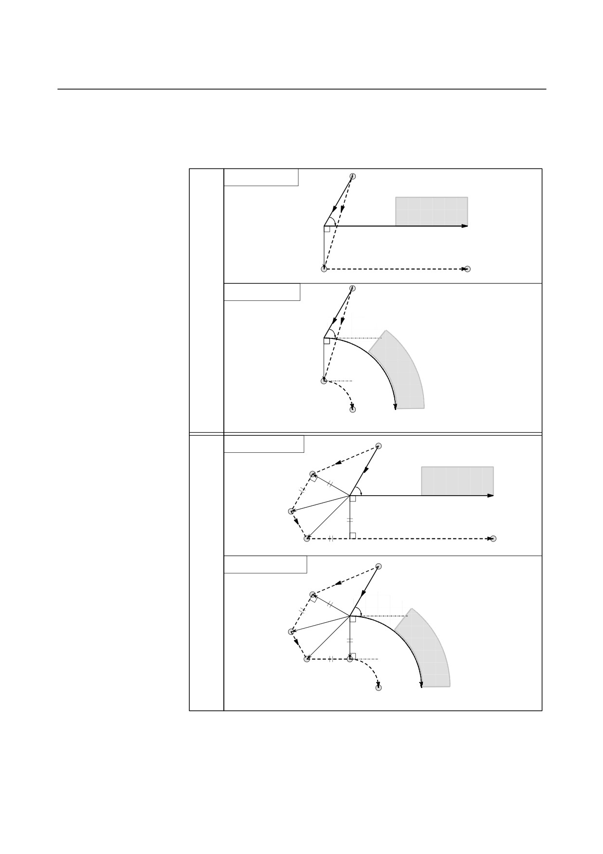
- Cases in which the start-up block is a block with tool movement and the tool
moves around the outside at an acute angle (α<90°)
Tool path in start-up has two types A and B, and they are selected by
parameter SUP (No.5003#0).
Linear→Linear
Start point
G42
Workpiece
α L
Programmed path
r
S
L
Tool nose radius center path
Type
A
Linear→Circular
Start point
G42
L
α
r
Work-
piece
S
C
Tool nose radius center path
Programmed path
Linear→Linear
Start point
(Linear connection type)
L
G42
Workpiece
r
α
L
Programmed path
r
L
S
L
L
Tool nose radius center path
Type
Linear→Circular
B
Start point
(Linear connection type)
L
G42
r
α
L
r
L
Work-
S
L
C
piece
Tool nose radius center path
Programmed path
- 193 -