FANUC Series 0i-MODEL D, Series 0i Mate-MODEL D. For Lathe System USER’S MANUAL - page 6
4. FUNCTIONS TO SIMPLIFY
PROGRAMMING
PROGRAMMING
B-64304EN-1/01
Explanation
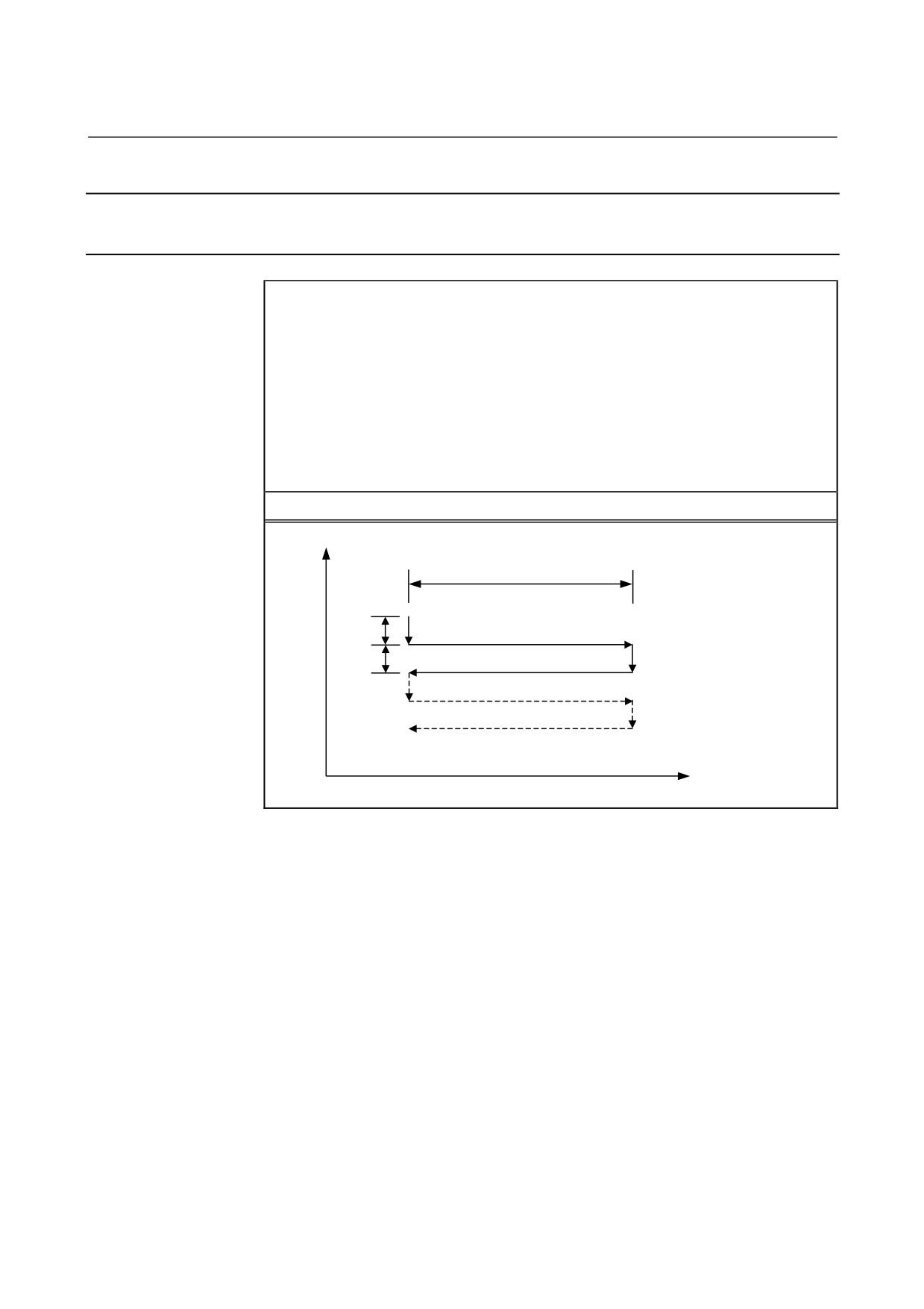
The traverse grinding cycle consists of six operations.
The operations from <1> to <6> are repeated until the repetitive count
specified in address H is reached. In the case of single block operation,
the operations from <1> to <6> are executed with one cycle start
operation.
- Operation sequence in a cycle
<1> Cutting with a grinding wheel
By the first depth of cut specified in A, cutting is performed by cutting
feed in the X-axis direction. The feedrate specified in I is used.
<2> Dwell
A dwell operation is performed for the time specified in U.
<3> Grinding
A movement is made by the distance specified in W by cutting feed.
Set a grinding axis in parameter No.5176. The feedrate specified in K
is used.
<4> Cutting with a grinding wheel
By the second depth of cut specified in B, cutting is performed by
cutting feed in the X-axis direction. The feedrate specified in I is used.
<5> Dwell
A dwell operation is performed for the time specified in U.
<6> Grinding (return direction)
A movement is made at the feedrate specified in K in the reverse
direction by the distance specified in W.
- 134 -
4.FUNCTIONS TO SIMPLIFY
B-64304EN-1/01
PROGRAMMING
PROGRAMMING
Limitation
- Cutting axis
As a cutting axis, the first controlled axis is used. By setting bit 0
(FXY) of parameter No. 5101 to 1, the axis can be switched using a
plane selection command (G17, G18, or G19).
- Grinding axis
Specify a grinding axis by setting an axis number for other than the
cutting axis in parameter No. 5176. Specify a grinding command in W
at all times without using an axis name. The axis name corresponding
to the set axis number can also be used for specification.
- A, B, W
The commands of A, B, and W are all incremental commands.
When none of A and B are specified or A=B=0, spark-out operation
(execution of only movement in the grinding direction) is performed.
- H
When H is not specified or H=0, the specification of H=1 is assumed.
The specification of H is valid only in the block where H is specified.
- Clear
The data A, B, W, U, I, and K in the canned cycle is modal
information common to G71, G72, G73, and G74. So, the data
remains valid until new data is specified. The data is cleared when a G
code of group 00 other than G04 or a G code of group 01 other than
G71, G72, G73, and G74 is specified. The specification of H is valid
only in the block where H is specified.
- B code
During the canned cycle, no B code (second auxiliary function) can be
specified.
NOTE
1 If no grinding axis is specified when G71 is
specified, alarm PS0455 is issued.
2 If the specified cutting axis number and grinding
axis number are the same, alarm PS0456 is
issued.
3 Even if G90 (absolute command) is specified while
this cycle is valid, each of the A, B, and W
commands is an incremental command.
- 135 -
4. FUNCTIONS TO SIMPLIFY
PROGRAMMING
PROGRAMMING
B-64304EN-1/01
4.5.2
Traverse Direct Constant-Size Grinding Cycle (G72)
A traverse direct constant-size grinding cycle can be executed.
Format
G72 P_ A_ B_ W_ U_ I_ K_ H_ ;
P_ : Gage number (1 to 4)
A_ : First depth of cut (The cutting direction depends on the sign.)
B_ : Second depth of cut (The cutting direction depends on the sign.)
W_ : Grinding range (The grinding direction depends on the sign.)
U_ : Dwell time
I_
: Feedrate for A and B
K_ : Feedrate for W
H_ : Repetitive count (from 1 to 9999)
G72
X
W
A
<1>(I)
<3>(K)
<2>U
<4>(I)
B
<6>(K)
<5>U
α
- 136 -
4.FUNCTIONS TO SIMPLIFY
B-64304EN-1/01
PROGRAMMING
PROGRAMMING
Explanation
If the multi-step skip option is specified, a gage number can be
specified. The method of gage number specification is the same as for
the multi-step skip option. If the multi-step skip option is not specified,
the conventional skip signal is used.
The commands and operations other than gage number specification
are the same as for G71.
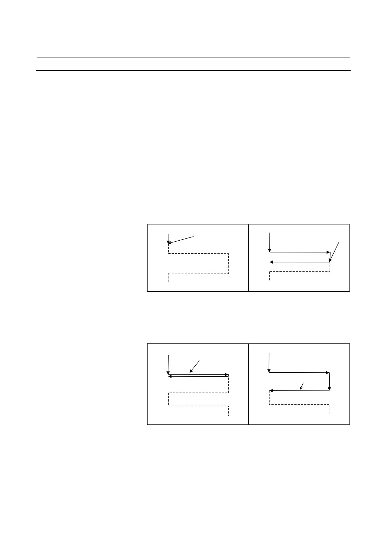
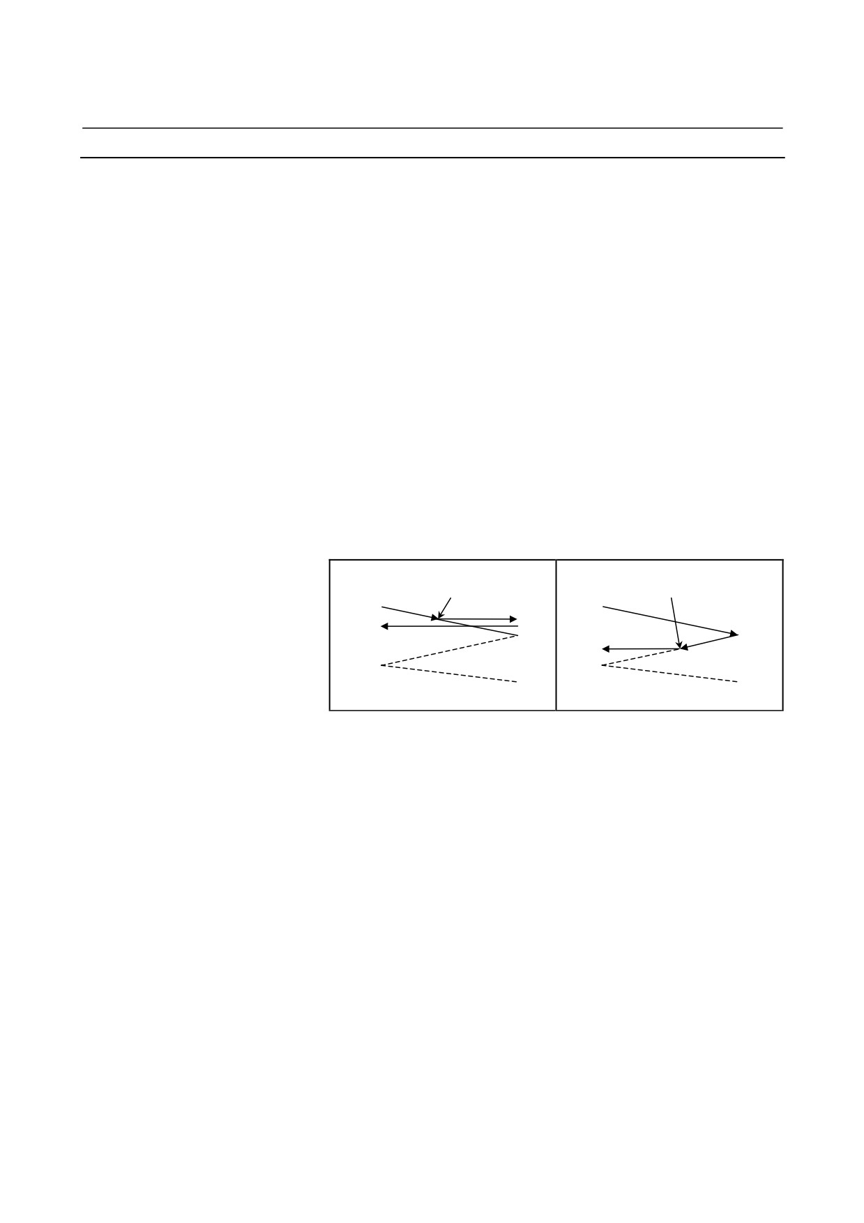
- Operation performed when the skip signal is input
A G72 cycle can be terminated after interrupting the current operation
(or after ending the current operation) by inputting the skip signal
during execution of the cycle.
Each operation of the sequence performed when the skip signal is
input is described below.
•
If the skip signal is input during operation
<1> or
<4>
(movement by A or B), cutting is immediately stopped to return
to coordinate α selected as the cycle start point.
Skip signal
Skip signal
(End)
(End)
•
If the skip signal is input during operation <2> or <5> (dwell),
dwell operation is immediately stopped to return to coordinate α
selected as the cycle start point.
•
If the skip signal is input during operation <3> or <6> (grinding
feed), the tool returns to coordinate α selected as the cycle start
point after the end of movement over W.
Skip signal
(End)
Skip signal
(End)
- 137 -
4. FUNCTIONS TO SIMPLIFY
PROGRAMMING
PROGRAMMING
B-64304EN-1/01
Limitation
- Cutting axis
As a cutting axis, the first controlled axis is used. By setting bit 0
(FXY) of parameter No. 5101 to 1, the axis can be switched using a
plane selection command (G17, G18, or G19).
- Grinding axis
Specify a grinding axis by setting an axis number for other than the
cutting axis in parameter No. 5177. Specify a grinding command in W
at all times without using an axis name. The axis name corresponding
to the set axis number can also be used for specification.
- P
If a value other than P1 to P4 is specified, the skip function is
disabled.
The specification of P is valid only in the block where P is specified.
- A, B, W
The commands of A, B, and W are all incremental commands.
When none of A and B are specified or A=B=0, spark-out operation
(execution of only movement in the grinding direction) is performed.
- H
When H is not specified or H=0, the specification of H=1 is assumed.
The specification of H is valid only in the block where H is specified.
- Clear
The data A, B, W, U, I, and K in the canned cycle is modal
information common to G71, G72, G73, and G74. So, the data
remains valid until new data is specified. The data is cleared when a G
code of group 00 other than G04 or a G code of group 01 other than
G71, G72, G73, and G74 is specified. The specification of P or H is
valid only in the block where P or H is specified.
- B code
During the canned cycle, no B code (second auxiliary function) can be
specified.
NOTE
1 If no grinding axis is specified when G72 is
specified, alarm PS0455 is issued.
2 If the specified cutting axis number and grinding
axis number are the same, alarm PS0456 is
issued.
3 Even if G90 (absolute command) is specified while
this cycle is valid, each of the A, B, and W
commands is an incremental command.
4 If a value from P1 to P4 is specified without
specifying the multi-step skip option, alarm
PS0370 is issued.
- 138 -
4.FUNCTIONS TO SIMPLIFY
B-64304EN-1/01
PROGRAMMING
PROGRAMMING
4.5.3
Oscillation Grinding Cycle (G73)
An oscillation grinding cycle can be executed.
Format
G73 A_ (B_) W_ U_ K_ H_ ;
A_ : First depth of cut (The cutting direction depends on the sign.)
B_ : Second depth of cut (The cutting direction depends on the sign.)
W_ : Grinding range (The grinding direction depends on the sign.)
U_ : Dwell time
K_ : Feedrate for W
H_ : Repetitive count (from 1 to 9999)
G73
X
W
<1>U
<2>(K)
A
<3>U
A(B)
<4>(K)
α
- 139 -
4. FUNCTIONS TO SIMPLIFY
PROGRAMMING
PROGRAMMING
B-64304EN-1/01
Explanation
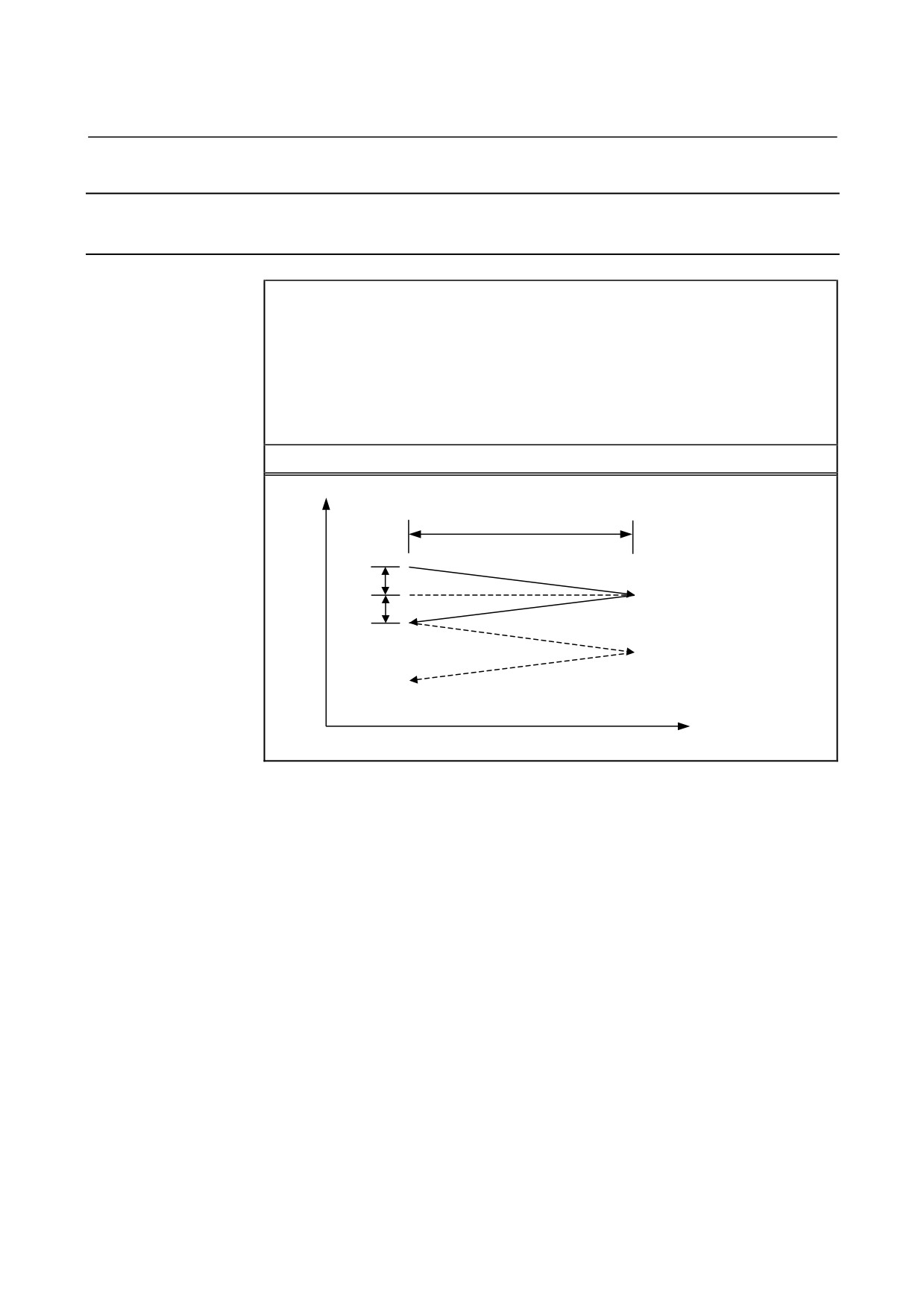
The oscillation grinding cycle consists of four operations.
The operations from <1> to <4> are repeated until the repetitive count
specified in address H is reached. In the case of single block operation,
the operations from <1> to <4> are executed with one cycle start
operation.
- Operation sequence in a cycle
<1> Dwell
A dwell operation is performed for the time specified in U.
<2> Cutting + grinding with a grinding wheel
Cutting feed is performed on the cutting axis (X-axis) and a grinding
axis at the same time. The amount of movement on the cutting axis
(depth of cut) is the first depth of cut specified in A, and the amount of
movement on a grinding axis is the distance specified in W. Set a
grinding axis in parameter No.5178. The feedrate specified in K is
used.
<3> Dwell
A dwell operation is performed for the time specified in U.
<4> Cutting + grinding with a grinding wheel (return direction)
Cutting feed is performed on the cutting axis (X-axis) and a grinding
axis at the same time. The amount of movement on the cutting axis
(depth of cut) is the second depth of cut specified in B, and the
amount of movement on the grinding axis is the distance specified in
W. The feedrate specified in K is used.
- 140 -
4.FUNCTIONS TO SIMPLIFY
B-64304EN-1/01
PROGRAMMING
PROGRAMMING
Limitation
- Cutting axis
As a cutting axis, the first controlled axis is used. By setting bit 0
(FXY) of parameter No. 5101 to 1, the axis can be switched using a
plane selection command (G17, G18, or G19).
- Grinding axis
Specify a grinding axis by setting an axis number for other than the
cutting axis in parameter No. 5178. Specify a grinding command in W
at all times without using an axis name. The axis name corresponding
to the set axis number can also be used for specification.
- B
If B is not specified, B=A is assumed.
The specification of B is valid only in the block where B is specified.
- A, B, W
The commands of A, B, and W are all incremental commands.
When none of A and B are specified or A=B=0, spark-out operation
(execution of only movement in the grinding direction) is performed.
- H
When H is not specified or H=0, the specification of H=1 is assumed.
The specification of H is valid only in the block where H is specified.
- Clear
The data A, W, U, and K in the canned cycle is modal information
common to G71, G72, G73, and G74. So, the data remains valid until
new data is specified. The data is cleared when a G code of group 00
other than G04 or a G code of group 01 other than G71, G72, G73,
and G74 is specified. The specification of B or H is valid only in the
block where B or H is specified.
- B code
During the canned cycle, no B code (second auxiliary function) can be
specified.
NOTE
1 If no grinding axis is specified when G73 is
specified, alarm PS0455 is issued.
2 If the specified cutting axis number and grinding
axis number are the same, alarm PS0456 is
issued.
3 Even if G90 (absolute command) is specified while
this cycle is valid, each of the A, B, and W
commands is an incremental command.
- 141 -
4. FUNCTIONS TO SIMPLIFY
PROGRAMMING
PROGRAMMING
B-64304EN-1/01
4.5.4
Oscillation Direct Constant-Size Grinding Cycle (G74)
An oscillation direct constant-size grinding cycle can be executed.
Format
G74 P_ A_ (B_) W_ U_ K_ H_ ;
P_ : Gage number (1 to 4)
A_ : First depth of cut (The cutting direction depends on the sign.)
B_ : Second depth of cut (The cutting direction depends on the sign.)
W_ : Grinding range (The grinding direction depends on the sign.)
U_ : Dwell time
K_ : Feedrate for W
H_ : Repetitive count (from 1 to 9999)
G74
X
W
<1>U
<2>(K)
A
A(B)
<3>U
<4>(K)
α
- 142 -
4.FUNCTIONS TO SIMPLIFY
B-64304EN-1/01
PROGRAMMING
PROGRAMMING
Explanation
If the multi-step skip option is specified, a gage number can be
specified. The method of gage number specification is the same as for
the multi-step skip option. If the multi-step skip option is not specified,
the conventional skip signal is used.
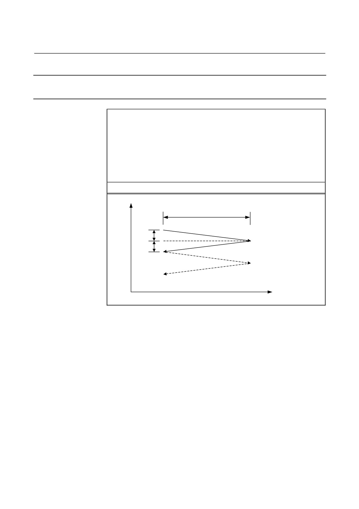
The commands and operations other than gage number specification
are the same as for G73.
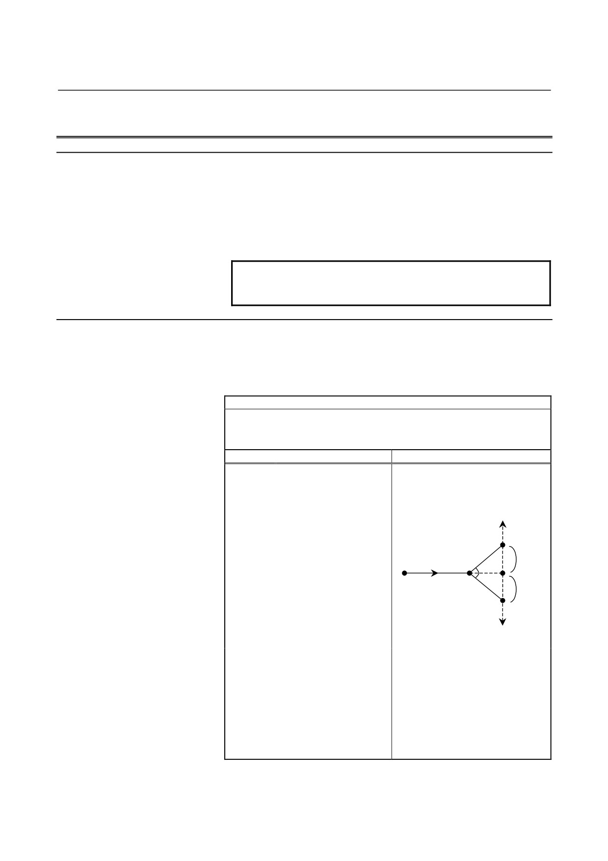
- Operation performed when the skip signal is input
A G74 cycle can be terminated after interrupting the current operation
(or after ending the current operation) by inputting the skip signal
during execution of the cycle.
Each operation of the sequence performed when the skip signal is
input is described below.
•
If the skip signal is input during operation <1> or <3> (dwell),
dwell operation is immediately stopped to return to coordinate α
selected as the cycle start point.
•
If the skip signal is input during operation <2> or <4> (A, B,
grinding feed), the tool returns to coordinate α selected as the
cycle start point after the end of movement over W.
Skip signal
Skip signal
(End)
(End)
- 143 -
4. FUNCTIONS TO SIMPLIFY
PROGRAMMING
PROGRAMMING
B-64304EN-1/01
Limitation
- Cutting axis
As a cutting axis, the first controlled axis is used. By setting bit 0
(FXY) of parameter No. 5101 to 1, the axis can be switched using a
plane selection command (G17, G18, or G19).
- Grinding axis
Specify a grinding axis by setting an axis number for other than the
cutting axis in parameter No. 5179. Specify a grinding command in W
at all times without using an axis name. The axis name corresponding
to the set axis number can also be used for specification.
- P
If a value other than P1 to P4 is specified, the skip function is
disabled.
The specification of P is valid only in the block where P is specified.
- B
If B is not specified, B=A is assumed.
The specification of B is valid only in the block where B is specified.
- A, B, W
The commands of A, B, and W are all incremental commands.
When none of A and B are specified or A=B=0, spark-out operation
(execution of only movement in the grinding direction) is performed.
- H
When H is not specified or H=0, the specification of H=1 is assumed.
The specification of H is valid only in the block where H is specified.
- Clear
The data A, W, U, and K in the canned cycle is modal information
common to G71, G72, G73, and G74. So, the data remains valid until
new data is specified. The data is cleared when a G code of group 00
other than G04 or a G code of group 01 other than G71, G72, G73,
and G74 is specified. The specification of P, B, or H is valid only in
the block where P, B, or H is specified.
- B code
During the canned cycle, no B code (second auxiliary function) can be
specified.
NOTE
1 If no grinding axis is specified when G74 is
specified, alarm PS0455 is issued.
2 If the specified cutting axis number and grinding
axis number are the same, alarm PS0456 is
issued.
3 Even if G90 (absolute command) is specified while
this cycle is valid, each of the A, B, and W
commands is an incremental command.
4 If a value from P1 to P4 is specified without
specifying the multi-step skip option, alarm PS0370
is issued.
- 144 -
4.FUNCTIONS TO SIMPLIFY
B-64304EN-1/01
PROGRAMMING
PROGRAMMING
4.6
CHAMFERING AND CORNER R
Overview
A chamfering or corner R block can automatically be inserted between
linear interpolation (G01) along a single axis and that along a single
axis normal to that single axis.
Chamfering or corner R is inserted for a command to move the tool
along two axes on the plane determined by the plane selection (G17,
G18, or G19) command.
NOTE
To enable the chamfering and corner R function,
bit 2 (CCR) of parameter No. 8134 to 1.
Format
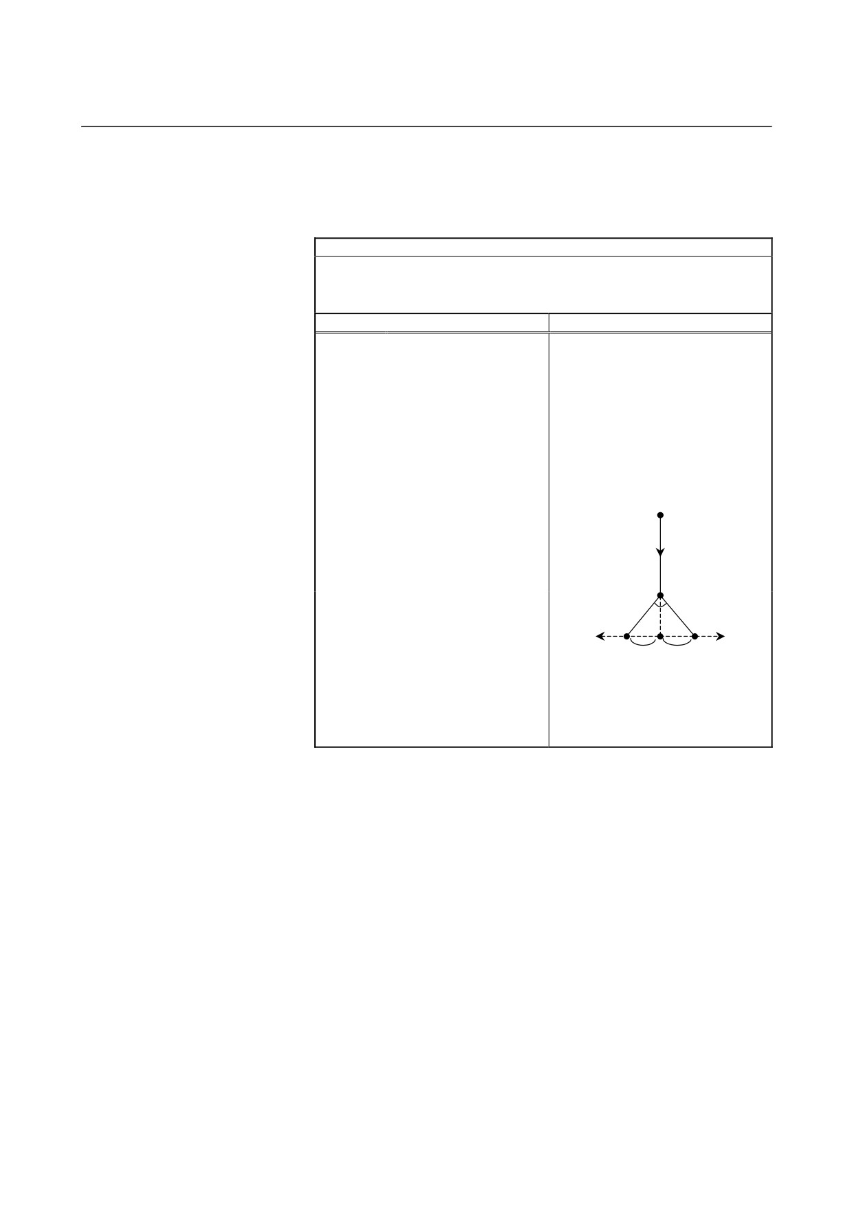
- Chamfering
First axis on the selected plane → second axis on the selected plane
(G17 plane: XP → YP, G18 plane: ZP → XP, G19 plane: YP → ZP)
Format
G17 plane: G01 XP(U)_ J(C)±j ;
G18 plane: G01 ZP(W)_ I(C)±i ;
G19 plane: G01 YP(V)_ K(C)±k ;
Explanation
Tool movement
XP(U)__
Specifies movement from
YP(V)__
point a to point b with an
ZP(W)__
absolute or incremental
programming in the figure
on the right.
Positive direction along
XP is the address of the
the second axis on the
selected plane
c
X-axis of the three basic
axes or an axis parallel to
i, j, k
a
d
the X-axis. YP is the
45°
b
45°
address of the Y-axis of the
Start point
i, j, k
three basic axes or an axis
Negative direction
c
parallel to the Y-axis. ZP is
along the second axis
the address of the Z-axis of
on the selected plane
the three basic axes or an
axis parallel to the Z-axis.
Moves from a to d and c.
I(C)±i
Specify the distance
(Positive direction along the second
J(C)±j
between points b and c in
axis on the selected plane when a
K(C)±k
the figure shown at right
plus sign is specified at I, J, K, or C
with a sign following
or negative direction when a minus
address I, J, K, or C. (Use
sign is specified at I, J, K, or C)
I, J, or K when bit 4 (CCR)
of parameter No. 3405 is
set to 0 or C when the bit is
set to 1.)
- 145 -
4. FUNCTIONS TO SIMPLIFY
PROGRAMMING
PROGRAMMING
B-64304EN-1/01
- Chamfering
Second axis on the selected plane → first axis on the selected plane
(G17 plane: YP → XP, G18 plane: XP → ZP, G19 plane: ZP → YP)
Format
G17 plane: G01 YP(V)_ I(C)±i ;
G18 plane: G01 XP(U)_ K(C)±k ;
G19 plane: G01 ZP(W)_ J(C)±j ;
Explanation
Tool movement
XP(U)__
Specifies movement from
YP(V)__
point a to point b with an
ZP(W)__
absolute or incremental
Moves from a to d and c.
programming in the figure
(Positive direction along the first axis
on the right.
on the selected plane when a plus
XP is the address of the
sign is specified at I, J, K, or C or
X-axis of the three basic
negative direction when a minus
axes or an axis parallel to
sign is specified at I, J, K, or C)
the X-axis. YP is the
address of the Y-axis of the
a
Start point
three basic axes or an axis
parallel to the Y-axis. ZP is
the address of the Z-axis of
the three basic axes or an
axis parallel to the Z-axis.
d
I(C)±i
Specify the distance
J(C)±j
between points b and c in
45°
45°
K(C)±k
the figure shown at right
b
First axis on
with a sign following
First axis on
c
c
the selected
i, j, k
i, j, k
the selected
address I, J, K, or C. (Use
plane
plane
I, J, or K when bit 4 (CCR)
of parameter No. 3405 is
set to 0 or C when the bit is
set to 1.)
- 146 -
4.FUNCTIONS TO SIMPLIFY
B-64304EN-1/01
PROGRAMMING
PROGRAMMING
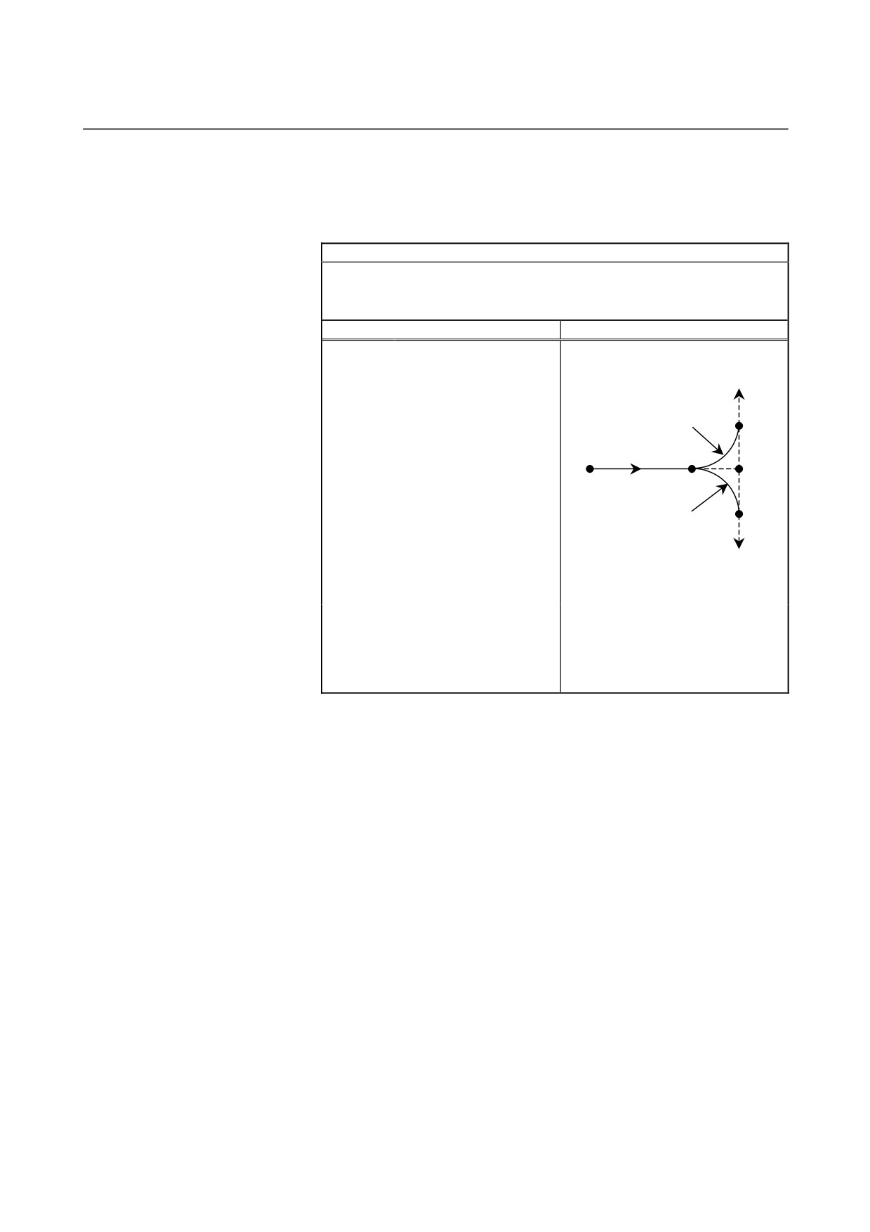
- Corner R
First axis on the selected plane → second axis on the selected plane
(G17 plane: XP → YP, G18 plane: ZP → XP, G19 plane: YP → ZP)
Format
G17 plane: G01 XP(U)_ R±r ;
G18 plane: G01 ZP(W)_ R±r ;
G19 plane: G01 YP(V)_ R±r ;
Explanation
Tool movement
XP(U)__
Specifies movement from
YP(V)__
point a to point b with an
ZP(W)__
absolute or incremental
Positive direction along
programming in the figure
the second axis on the
selected plane
c
on the right.
r
XP is the address of the
a
d
X-axis of the three basic
b
axes or an axis parallel to
Start point
the X-axis. YP is the
address of the Y-axis of the
r
c
three basic axes or an axis
Negative direction along
the second axis on the
parallel to the Y-axis. ZP is
selected plane
the address of the Z-axis of
the three basic axes or an
Moves from a to d and c.
axis parallel to the Z-axis.
(Positive direction along the second
R±r
Specify the radius of the
axis on the selected plane when +r
arc connecting points d
is specified at R or negative
and c in the figure shown
direction when -r is specified at R)
at right with a sign following
address R.
- 147 -
4. FUNCTIONS TO SIMPLIFY
PROGRAMMING
PROGRAMMING
B-64304EN-1/01
- Corner R
Second axis on the selected plane → first axis on the selected plane
(G17 plane: YP → XP, G18 plane: XP → ZP, G19 plane: ZP → YP)
Format
G17 plane: G01 YP(V)_ R±r ;
G18 plane: G01 XP(U)_ R±r ;
G19 plane: G01 ZP(W)_ R±r ;
Explanation
Tool movement
XP(U)__
Specifies movement from
YP(V)__
point a to point b with an
ZP(W)__
absolute or incremental
Moves from a to d and c.
programming in the figure
(Positive direction along the first axis
on the right.
on the selected plane when +r is
specified at R or negative direction
XP is the address of the
X-axis of the three basic
when -r is specified at R)
axes or an axis parallel to
a Start point
the X-axis. YP is the
address of the Y-axis of the
three basic axes or an axis
parallel to the Y-axis. ZP is
the address of the Z-axis of
d
r
r
the three basic axes or an
axis parallel to the Z-axis.
R±r
Specify the radius of the
First axis on
c
b
c
First axis on
the selected
the selected
arc connecting points d
plane
plane
and c in the figure shown
at right with a sign following
address R.
- 148 -
4.FUNCTIONS TO SIMPLIFY
B-64304EN-1/01
PROGRAMMING
PROGRAMMING
Explanation
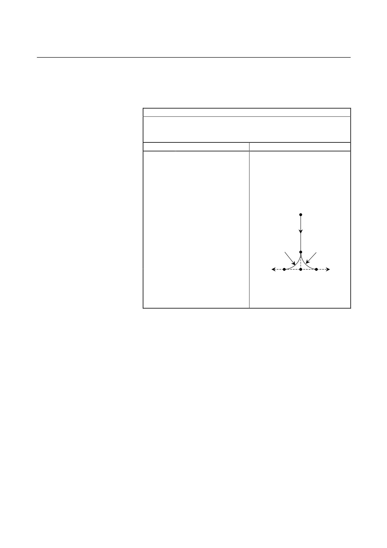
By G01 specified for chamfering or corner R, the tool must be moved
only along one of the two axes on the selected plane. The command in
the next block must move the tool only along the other axis on the
selected plane.
Example:
When the A-axis is set as an axis parallel to the basic X-axis (by
setting parameter No.
1022 to
5), the following program
performs chamfering between cutting feed along the A-axis and
that along the Z-axis:
G18 A0 Z0
G00 A100.0 Z100.0
G01 A200.0 F100 K30.0
Z200.0
The following program causes an alarm. (Because chamfering is
specified in the block to move the tool along the X-axis, which is
not on the selected plane)
G18 A0 Z0
G00 A100.0 Z100.0
G01 X200.0 F100 K30.0
Z200.0
The following program also causes an alarm. (Because the block
next to the chamfering command moves the tool along the X-axis,
which is not on the selected plane)
G18 A0 Z0
G00 A100.0 Z100.0
G01 Z200.0 F100 I30.0
X200.0
A radius value is specified at I, J, K, R, and C.
In an incremental programming, use point b in the figure in "Format"
as the start point in the block next to a chamfering or corner R block.
That is, specify the distance from point b. Do not specify the distance
from point c.
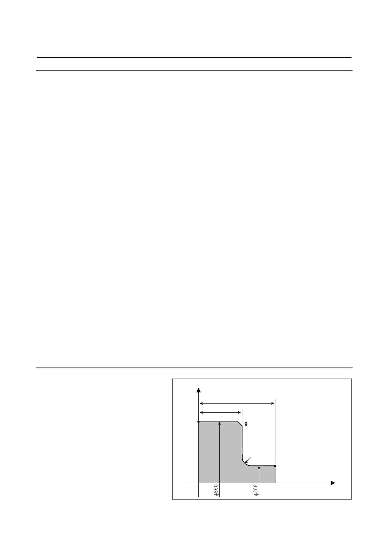
Example
X
N001 G18 ;
N002 G00 X268.0 Z530.0 ;
530.0
N003 G01 Z270.0 R6.0 ;
N004 X860.0 K-3.0 ;
270.0
N005 Z0 ;
N004
End point
K3.0
N003
R6
N002
Cutting start point
Z
- 149 -
4. FUNCTIONS TO SIMPLIFY
PROGRAMMING
PROGRAMMING
B-64304EN-1/01
Limitation
- Alarms
In the following cases, an alarm is issued:
1)
Chamfering or corner R is specified in a block for threading
(alarm PS0050).
2)
G01 is not specified in the block next to the G01 block in which
chamfering or corner R is specified (alarm PS0051 or PS0052).
3)
An axis which is not on the selected plane is specified as a move
axis in the block in which chamfering or corner R is specified or
the next block (alarm PS0051 or PS0052).
4)
A plane selection command (G17, G18, or G19) is specified in
the block next to the block in which chamfering or corner R is
specified (alarm PS0051).
5)
When bit 4 (CCR) of parameter No. 3405 is set to 0 (to specify
chamfering at I, J, or K), two or more of I, J, K, and R are
specified in G01 (alarm PS0053).
6)
Chamfering or corner R is specified in the G01 block to move the
tool along more than one axis (alarm PS0054).
7)
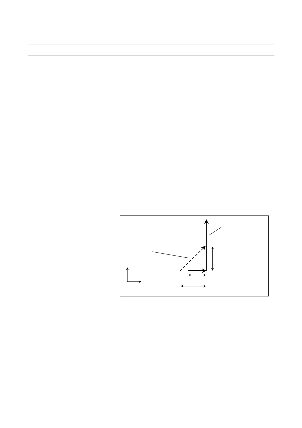
The travel distance along an axis specified in the block in which
chamfering or corner R is specified is smaller than the amount of
chamfering or corner R (alarm PS0055). (See the figure below.)
G18
The solid line indicates
G01 W30.0 F100.0 I50.0 ;
the tool path when
G01 U100.0 ;
chamfering is not
performed.
Chamfering block to
be inserted
50.0
x
30.0 (smaller than 50.0)
z
50.0
Fig. 4.6 (a) Example of machining which causes alarm PS0055
8)
An invalid combination of a move axis and I, J, or K is specified
for chamfering (alarm PS0306).
- 150 -
4.FUNCTIONS TO SIMPLIFY
B-64304EN-1/01
PROGRAMMING
PROGRAMMING
9)
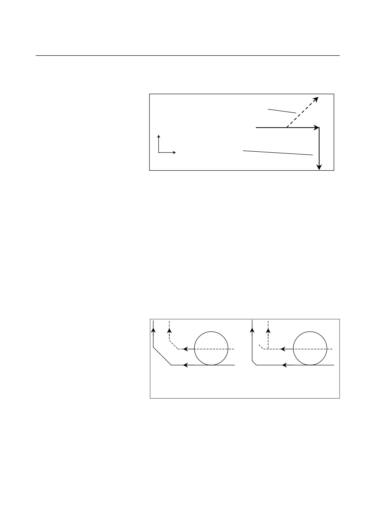
An invalid sign is specified at I, J, K, R, or C (chamfering or
corner R in the direction opposite to the movement in the next
block is specified) (alarm PS0051). (See the figure below.)
Chamfering block to
G18
be inserted (positive X
G01 W100.0 F100.0 I50.0 ;
direction)
G01 U-100.0 ;
The solid line indicates the
x
tool path when chamfering
is not performed.
z
(negative X direction)
Fig. 4.6 (b) Example of machining which causes alarm PS0051
- Single block operation
When the block in which chamfering or corner R is specified is
executed in the single block mode, operation continues to the end
point of the inserted chamfering or corner R block and the machine
stops in the feed hold mode at the end point. When bit 0 (SBC) of
parameter No. 5105 is set to 1, the machine stops in the feed hold
mode also at the start point of the inserted chamfering or corner R
block.
- Tool nose radius compensation
When applying tool nose radius compensation, note the following
points:
1.
If the amount of inner chamfering or corner R is too small as
compared with compensation and cutting is generated, alarm
PS0041 is issued. (See the figure below.)
Example of machining which does not
Example of machining which
cause alarm PS0041
causes alarm PS0041
(The solid line indicates the programmed path after chamfering. The
dotted line indicates the tool center path or tool nose radius center path.)
2.
A function is available which intentionally changes the
compensation direction by specifying the I, J, or K command in
the G01 block in the tool nose radius compensation mode (see
the explanations of tool nose radius compensation). To use this
function when the chamfering and corner R function is enabled
(bit 2 (CCR) of parameter No. 8134 is set to 1), set bit 4 (CCR)
of parameter No.
3405 is set to
1 so that the I, J, and K
commands are not used as chamfering commands. Operation to
be performed under each condition is explained below.
- 151 -
4. FUNCTIONS TO SIMPLIFY
PROGRAMMING
PROGRAMMING
B-64304EN-1/01
(1) When the chamfering and corner R function is not used (bit 2
(CCR) of parameter No.8134 = 0)
In the G01 block in the tool nose radius compensation mode, the
tool nose radius compensation direction can be specified at
address I, J, or K.
No chamfering is performed.
(2) When the chamfering and corner R function is used (bit 2 (CCR)
of parameter No.8134 = 1)
(2-1) When bit 4 (CCR) of parameter No. 3405 is set to 0
In the G01 block in the tool nose radius compensation
mode, chamfering can be specified at address I, J, or K.
Corner R can also be specified at address R.
The tool nose radius compensation direction cannot be
specified.
(2-2) When bit 4 (CCR) of parameter No. 3405 is set to 1
In the G01 block in the tool nose radius compensation
mode, the tool nose radius compensation direction can be
specified at address I, J, or K.
Chamfering or corner R can also be specified at address
C or R.
- Direct drawing dimension programming
The chamfering and corner R function and direct drawing dimension
programming cannot be used simultaneously.
When the chamfering and corner R function is enabled (bit 2 (CCR) of
parameter No. 8134 is set to 1), bit 0 (CRD) of parameter No. 3453
can be set to 1 to enable direct drawing dimension programming.
(With this setting, the chamfering and corner R function is disabled.)
- 152 -
4.FUNCTIONS TO SIMPLIFY
B-64304EN-1/01
PROGRAMMING
PROGRAMMING
4.7
MIRROR IMAGE FOR DOUBLE TURRET (G68, G69)
Overview
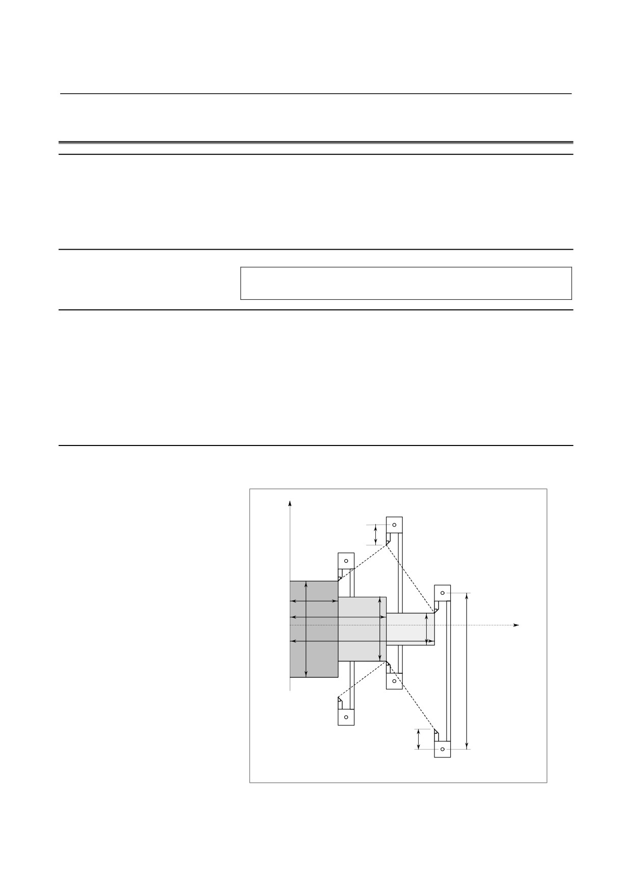
When a unit has a double turret consisting of two tool posts which
face each other on the same controlled axis, mirror image can be
applied to the X-axis with a G code command. Symmetrical cutting
can be performed by creating a machining program for the facing tool
posts as if they were in the coordinate system on the same side.
Format
G68 : Double turret mirror image on
G69 : Mirror image cancel
Explanation
Mirror image can be applied to the X-axis of the three basic axes that
is set by parameter No. 1022 with the G code command.
When G68 is designated, the coordinate system is shifted to the
double turret side, and the X-axis sign is reversed from the
programmed command to perform symmetrical cutting. This function
is called the mirror image for double turret.
To use this function, set the distance between the two tool posts to a
parameter No. 1290.
Example
• For turning
X
Offset value of tool
post A
<3>
Tool post A
60
120
<1>
Z
φ80
φ40
180
φ120
<2>
120
Offset value of tool
post B
Tool post B
- 153 -

4. FUNCTIONS TO SIMPLIFY
PROGRAMMING
PROGRAMMING
B-64304EN-1/01
X40.0 Z180.0 T0101 ; Position tool post A at <1>
G68 ;
Shift the coordinate system by the distance A to B
(120mm), and turn mirror image on.
X80.0 Z120.0 T0202 ; Position tool post B at <2>
G69 ;
Shift the coordinate system by the distance B to A,
and cancel mirror image.
X120.0 Z60.0 T0101 ; Position tool post A at <3>
NOTE
A diameter value is specified for the X-axis.
Limitation
NOTE
1 When the G68 command based on this function is
enabled, the X-axis coordinate value that can be
read with the custom macro system variables
#5041 and up or #100101 and up (current specified
position (in the workpiece coordinate system)) is a
position with mirror image applied.
2 This function cannot be used together with the
balanced cutting function (for a 2-path system).
To use this function, set bit 0 (NVC) of parameter
No. 8137 to 1.
- 154 -
4.FUNCTIONS TO SIMPLIFY
B-64304EN-1/01
PROGRAMMING
PROGRAMMING
4.8
DIRECT DRAWING DIMENSION PROGRAMMING
Overview
Angles of straight lines, chamfering value, corner R values, and other
dimensional values on machining drawings can be programmed by
directly inputting these values. In addition, the chamfering and corner
R can be inserted between straight lines having an optional angle.
This programming is only valid in memory operation mode.
NOTE
To use direct drawing dimension programming
when the chamfering and corner R function is
enabled (bit 2 (CCR) of parameter No. 8134 is set
to 1), set bit 0 (CRD) of parameter No. 3453 to 1.
(With this setting, the chamfering and corner R
function is disabled.)
Format
Examples of command formats for the G18 plane (ZX plane) are
shown. This function can be specified in the following formats also
for the G17 plane (XY plane) and G19 plane (YZ plane).
The following formats are changed as follows:
For the G17 plane: Z → X, X → Y
For the G19 plane: Z → Y, X → Z
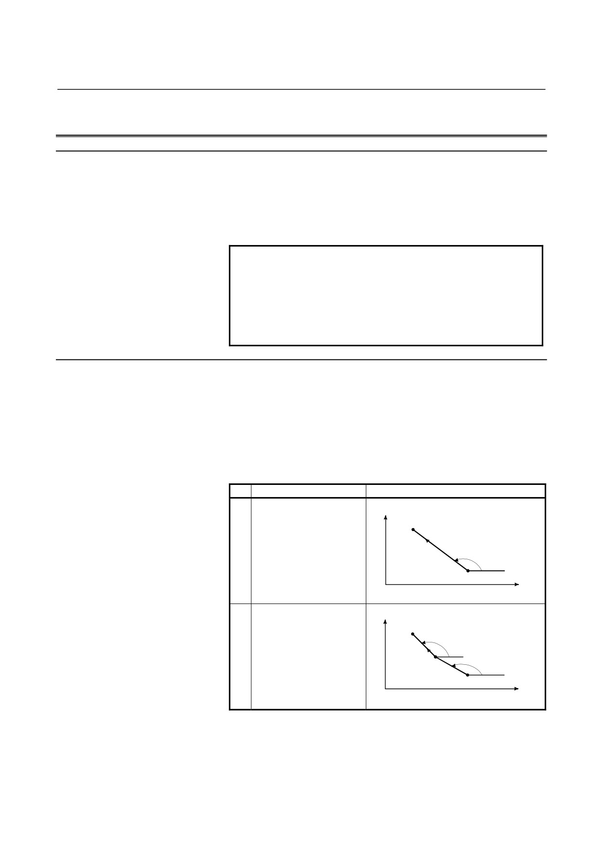
Table 4.8 (a) Commands table
Commands
Movement of tool
X
(X2 , Z2)
1
X2_ (Z2_), A_ ;
A
(X1 , Z1)
Z
X
(X3 , Z3)
A2
,A1_ ;
2
X3_ Z3_, A2_ ;
(X2 , Z2)
A1
(X1 , Z1)
Z
- 155 -
4. FUNCTIONS TO SIMPLIFY
PROGRAMMING
PROGRAMMING
B-64304EN-1/01
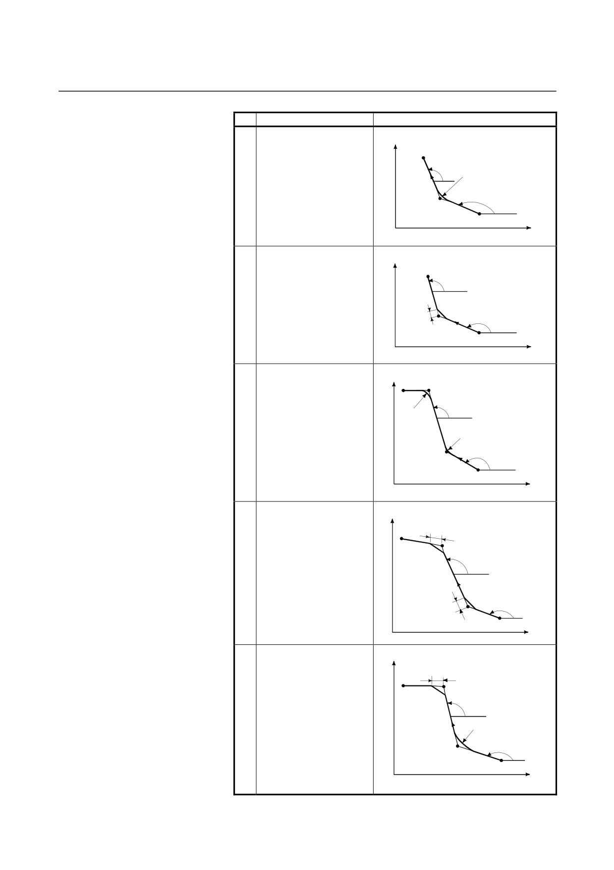
Commands
Movement of tool
X
(X3 , Z3)
X2_ Z2_, R1_ ;
A2
X3_ Z3_ ;
R1
3
or
A1
,A1_, R1_ ;
(X2 , Z2)
X3_ Z3_, A2_ ;
(X1 , Z1)
Z
X
(X3 , Z3)
X2_ Z2_, C1_ ;
A2
X3_ Z3_ ;
4
or
,A1_, C1_ ;
C1
A1
X3_ Z3_, A2_ ;
(X2 , Z2)
(X1 , Z1)
Z
X
(X4 , Z4)
(X3 , Z3)
X2_ Z2_ , R1_ ;
X3_ Z3_ , R2_ ;
A2
R2
X4_ Z4_ ;
5
or
R1
,A1_, R1_ ;
A1
X3_ Z3_, A2_, R2_ ;
(X2 , Z2)
X4_ Z4_ ;
(X1 , Z1)
Z
X
C2
X2_ Z2_ , C1_ ;
X3_ Z3_ , C2_ ;
(X3 , Z3)
(X4 , Z4)
X4_ Z4_ ;
A2
6
or
,A1_, R1_ ;
(X2 , Z2)
X3_ Z3_, A2_, C2_ ;
A1
X4_ Z4_ ;
C1
(X1 , Z1)
Z
X
C2
X2_ Z2_ , R1_ ;
(X3 , Z3)
X3_ Z3_ , C2_ ;
(X4 , Z4)
A2
X4_ Z4_ ;
7
or
,A1_, R1_ ;
R1
X3_ Z3_, A2_, C2_ ;
A1
(X2 , Z2)
X4_ Z4_ ;
(X1 , Z1)
Z
- 156 -
4.FUNCTIONS TO SIMPLIFY
B-64304EN-1/01
PROGRAMMING
PROGRAMMING
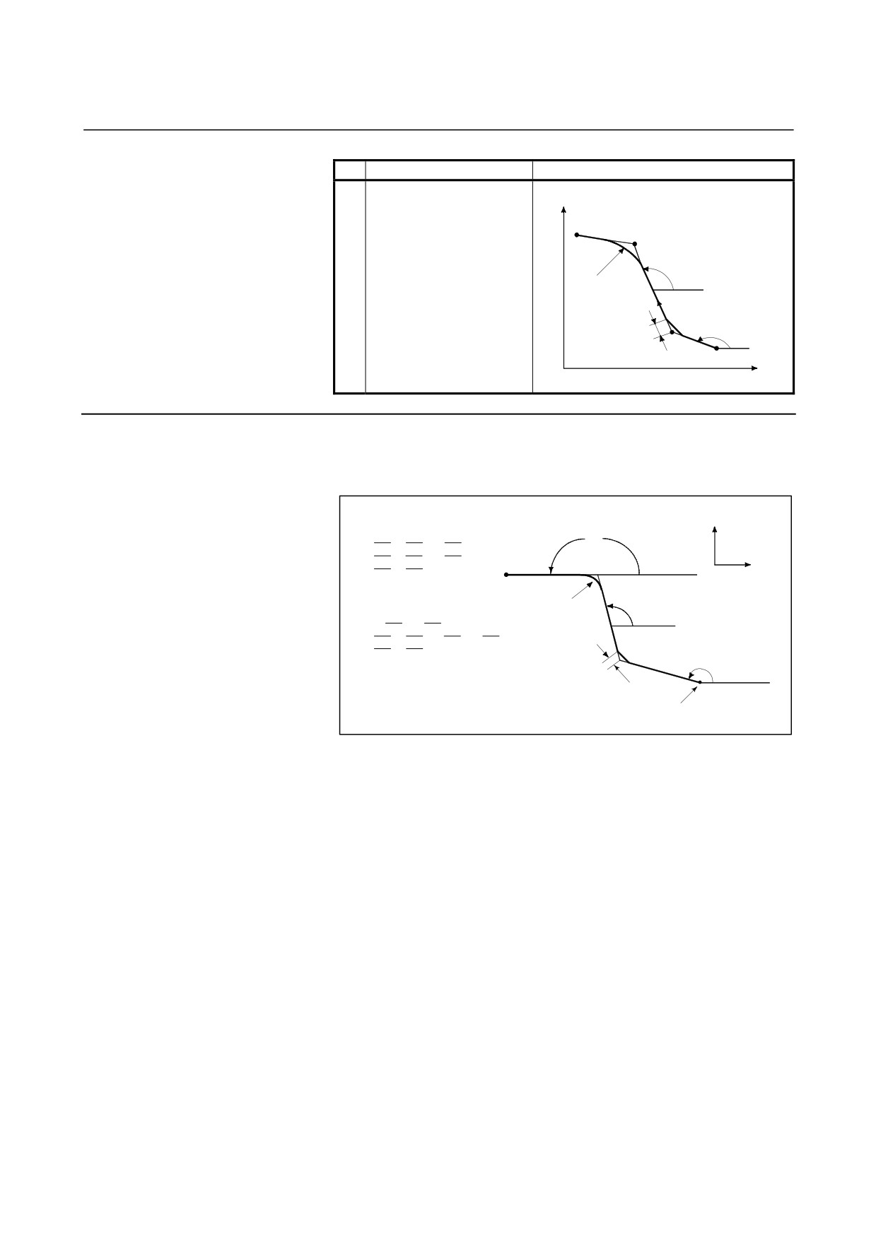
Commands
Movement of tool
X
(X4 , Z4)
X2_ Z2_ , C1_ ;
(X3 , Z3)
X3_ Z3_ , R2_ ;
X4_ Z4_ ;
A2
R2
8
or
,A1_, C1_ ;
(X2 , Z2)
X3_ Z3_, A2_, R2_ ;
C1
A1
X4_ Z4_ ;
(X1 , Z1)
Z
Explanation
A program for machining along the curve shown in Fig. 4.8 (a) is as
follows :
+X
X (x2) Z (z2) , C (c1) ;
a3
X (x3) Z (z3) , R (r2) ;
X (x4) Z (z4) ;
(x3, z3)
+Z
(x4, z4)
or
r2
a2
,A (a1) , C (c1) ;
X (x3) Z (z3) , A (a2) , R (r2) ;
X (x4) Z (z4) ;
(x2, z2)
a
1
c1
(x1, z1)
Start
Fig. 4.8 (a) Machining Drawing (example)
For command a straight line, specify one or two out of X, Z, and A.
If only one is specified, the straight line must be primarily defined by
a command in the next block.
To command the degree of a straight line or the value of chamfering
or corner R, command with a comma (,) as follows :
,A_
,C_
,R_
By specifying 1 to bit 4 (CCR) of parameter No.3405 on the system
which does not use A or C as an axis name, the degree of a straight
line or the value of chamfering or corner R can be commanded
without a comma (,) as follows :
A_
C_
R_
- 157 -
4. FUNCTIONS TO SIMPLIFY
PROGRAMMING
PROGRAMMING
B-64304EN-1/01
- Command using a supplement
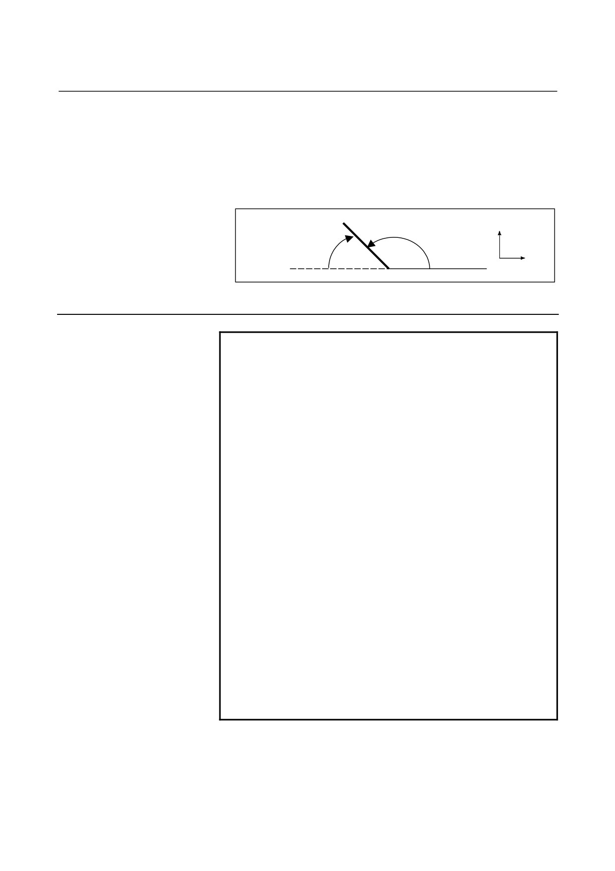
When bit 5 (DDP) of parameter No. 3405 is set to 1, an angle can be
specified using a supplement.
There is the following relationship, assuming that the supplement is A'
and the actual specified angle is A:
A = 180 - A'
+X
A
A’
+Z
Fig. 4.8 (b) Supplement
Limitation
NOTE
1
Direct drawing dimension programming commands
are valid only during memory operation.
2
The following G codes are not applicable to the same
block as commanded by direct input of drawing
dimensions or between blocks of direct input of
drawing dimensions which define sequential figures.
(a) G codes other than G04 in group 00
(b) G codes other than G00, G01, and G33 in group
01
(c) G codes in group 10 (canned cycle for drilling)
(d) G codes in group 16 (plane selection)
(e) G22 and G23
3
Corner R cannot be inserted into a threading block.
4
When the chamfering and corner R function is
enabled (bit 2 (CCR) of parameter No. 8134 is set to
1), both functions cannot be used simultaneously.
When bit 0 (CRD) of parameter No. 3453 is set to 1,
direct drawing dimension programming is enabled. (At
this time, chamfering and corner R are disabled.)
5
When the end point of the previous block is
determined in the next block according to sequential
commands of direct drawing dimension programming
during single block operation, the machine does not
stop in the single block stop mode, but stop in the
feed hold stop mode at the end point of the previous
block.
- 158 -

4.FUNCTIONS TO SIMPLIFY
B-64304EN-1/01
PROGRAMMING
PROGRAMMING
NOTE
6
The angle allowance in calculating the point of
intersection in the program below is ±1°.
(Because the travel distance to be obtained in this
calculation is too large.)
(a) X_ ,A_ ; (If a value within 0°±1° or 180°±1° is
specified for the angle instruction A, the alarm
PS0057 occurs.)
(b) Z_ ,A_ ; (If a value within 90°±1° or 270°±1° is
specified for the angle instruction A, the alarm
PS0057 occurs.)
7
An alarm PS0058 occurs if the angle made by the 2
lines is within ±1° when calculating the point of
intersection.
8
Chamfering or corner R is ignored if the angle made
by the 2 lines is within ±1°.
9
Both a dimensional command (absolute
programming) and angle instruction must be specified
in the block following a block in which only the angle
instruction is specified.
(Example)
N1 X_ ,A_ ,R_ ;
N2 ,A_ ;
N3 X_ Z_ ,A_ ;
In addition to the dimensional command, angle
command must be specified in block No. 3. If the
angle command is not specified, alarm PS0056 is
issued. If the coordinates are not specified with an
absolute programming, alarm PS0312 is issued.
10
In the tool nose radius compensation mode, a block in
which only the angle command is specified in direct
drawing dimension programming is assumed to be a
block with no move command. For details of
compensation when sequential blocks with no move
command are specified, see the explanation of tool
nose radius compensation.
11
If two or more blocks with no move command are
specified between sequential commands of direct
drawing dimension programming, alarm PS0312 is
issued.
12
When bit 4 (CCR) of parameter No. 3405 is set to 1,
address A in the G76 (multiple threading cycle) block
specifies the tool nose angle.
When A or C is used as an axis name, it cannot be
used in the angle or chamfering command in direct
drawing dimension programming. Use ,A_ or ,C_
(when bit 4 (CCR) of parameter No. 3405 is set to 0).
- 159 -
4. FUNCTIONS TO SIMPLIFY
PROGRAMMING
PROGRAMMING
B-64304EN-1/01
NOTE
13 In a multiple repetitive canned cycle, in blocks with
sequence numbers between those specified at P and
Q, a program using direct drawing dimension
programming can be used. The block with the last
sequence number specified at Q must not be an
intermediate block of these specified blocks.
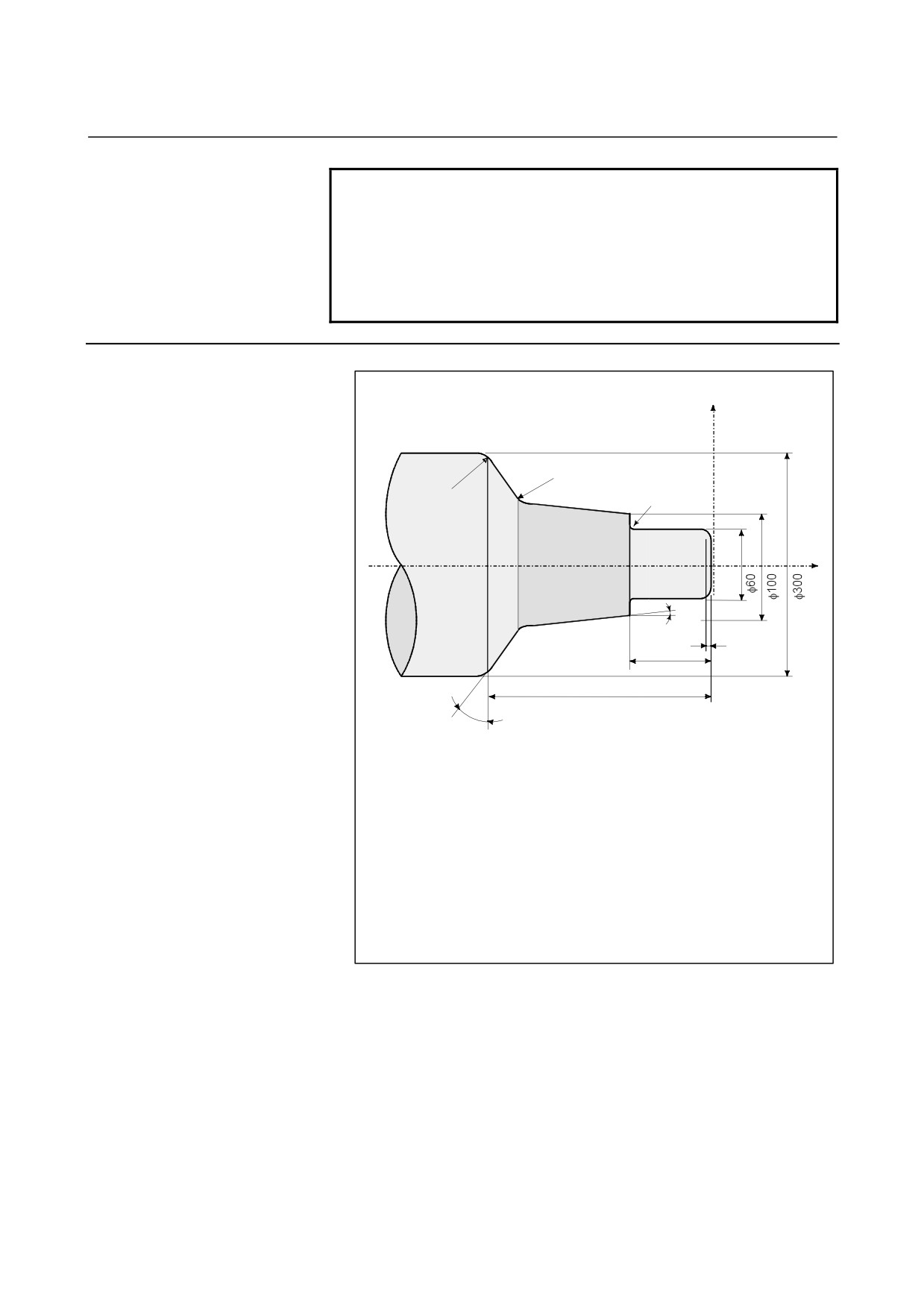
Example
X
R20
R15
R6
Z
10°
1 × 45°
30
180
22°
(Diameter specification, metric input)
N001 G50 X0.0 Z0.0 ;
N002 G01 X60.0 ,A90.0 ,C1.0 F80 ;
N003 Z-30.0 ,A180.0 ,R6.0 ;
N004 X100.0 ,A90.0 ;
N005
,A170.0 ,R20.0 ;
N006
X300.0 Z-180.0 ,A112.0 ,R15.0 ;
N007
Z-230.0 ,A180.0 ;
:
:
- 160 -
B-64304EN-1/01
PROGRAMMING
5.COMPENSATION FUNCTION
5
COMPENSATION FUNCTION
Chapter
5, "COMPENSATION FUNCTION", consists of the
following sections:
5.1 TOOL OFFSET
162
5.2 OVERVIEW OF TOOL NOSE RADIUS COMPENSATION
(G40-G42)
168
5.3 DETAILS OF TOOL NOSE RADIUS COMPENSATION
185
5.4 CORNER CIRCULAR INTERPOLATION (G39)
242
5.5 AUTOMATIC TOOL OFFSET (G36, G37)
244
- 161 -
5.COMPENSATION FUNCTION
PROGRAMMING
B-64304EN-1/01
5.1
TOOL OFFSET
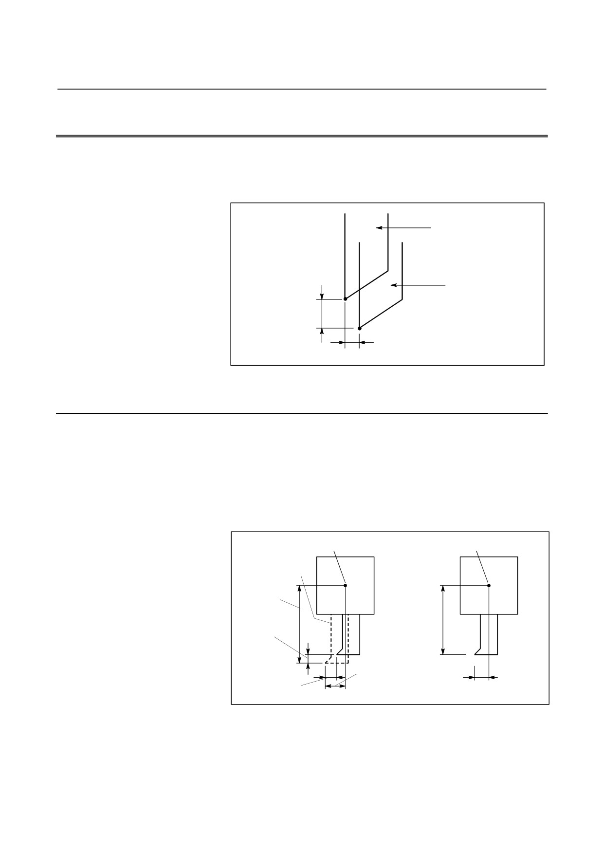
Tool offset is used to compensate for the difference when the tool
actually used differs from the imagined tool used in programming
(usually, standard tool).
Standard tool
Actual tool
Offset amount
on X axis
Offset amount
on Z axis
Fig. 5.1 (a) Tool offset
5.1.1
Tool Geometry Offset and Tool Wear Offset
Tool geometry offset and tool wear offset are possible to divide the
tool offset to the tool geometry offset for compensating the tool shape
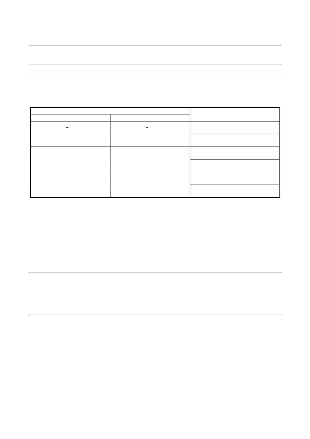
or tool mounting position and the tool wear offset for compensating
the tool nose wear. The tool geometry offset value and tool wear
offset value can be set individually. When these values are not
distinguished from each other, the total of the values is set as the tool
offset value.
Point on the program
Point on the program
Imaginary tool
X axis
geometry
Offset
offset
amount
value
on X axis
X axis
wear
offset
value
Z axis
Z axis
wear
geometry
Offset
offset
offset
amount
value
value
on Z axis
Fig. 5.1.1 (a) If tool geometry offset and tool wear offset are
distinguished from each other (left) and if they are
not (right)
- 162 -
B-64304EN-1/01
PROGRAMMING
5.COMPENSATION FUNCTION
5.1.2
T Code for Tool Offset
Format
Select a tool with a numeric value after a T code. A part of the
numeric value is used as a tool offset number for specifying data such
as a tool offset value. The following selections can be made
according to the specification method and parameter setting:
Meaning of T code (*1)
Parameter setting for specifying of
LGN(No.5002#1)=0
LGN(No.5002#1)=1
offset No. (*2)
T x x x x x x x y
T x x x x x x x y
A tool wear offset number is specified
xxxxxxx : Tool selection
xxxxxxx : Tool selection and tool
using the lower one digit of a T code.
y
: Tool wear and tool
geometry offset
When parameter No. 5028 is set to 1
geometry offset
y
: Tool wear offset
T x x x x x x y y
T x x x x x x y y
A tool wear offset number is specified
xxxxxx
: Tool selection
xxxxxx
: Tool selection and tool
using the lower two digits of a T code.
yy
: Tool wear and tool
geometry offset
When parameter No. 5028 is set to 2
geometry offset
yy
: Tool wear offset
T x x x x x y y y
T x x x x x y y y
A tool wear offset number is specified
xxxxx
: Tool selection
xxxxx
: Tool selection and tool
using the lower three digits of a T code.
yyy
: Tool wear and tool
geometry offset
When parameter No. 5028 is set to 3
geometry offset
yyy
: Tool wear offset
*1 The maximum number of digits of a T code can be specified
using parameter No. 3032.
(1 to 8 digits)
*2 When parameter No. 5028 is set to 0, the number of digits of a T
code used for offset number specification depends on the number
of tool offsets.
Example)
When the number of tool offsets is 1 to 9: Lower one digit
When the number of tool offsets is 10 to 99: Lower two digits
When the number of tool offsets is 100 to 200: Lower three digits
5.1.3
Tool Selection
Tool selection is made by specifying the T code corresponding to the
tool number. Refer to the machine tool builder's manual for the
relationship between the tool selection number and the tool.
5.1.4
Offset Number
Tool offset number has two meanings. It is specifies the offset
distance corresponding to the number that is selected to begin the
offset function. A tool offset number of 0 indicates that the offset
amount is 0 and the offset is cancelled.
- 163 -