FANUC Series 0i-MODEL D, FANUC Series 0i Mate-MODEL D. MAINTENANCE MANUAL - page 11
7.EMBEDDED ETHERNET FUNCTION
B-64305EN/03
#5 SI2 Soft key input of the characters shown below and switching between the uppercase and
lowercase input modes by a soft key are:
0: Disabled.
1: Enabled.
( ) ? * & @ _
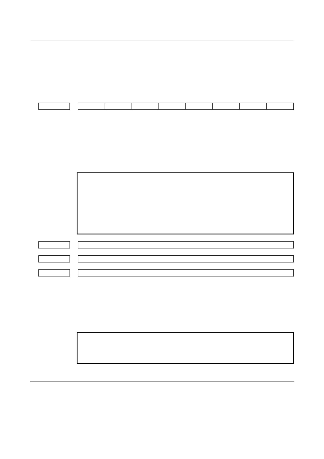
For embedded Ethernet port
#7
#6
#5
#4
#3
#2
#1
#0
14880
PCH
[Input type] Setting input
[Data type] Bit
#1 PCH When communication based on the FTP file transfer function starts, an FTP server
presence check based on PING is:
0: Made
1: Not made
NOTE
Generally, set this parameter to 0 so that an FTP server presence
check based on PING is performed.
Otherwise, if the server is not present in the network, it takes
several tens of seconds to detect an error.
Some PCs are set not to response to the PING command mainly
for security purposes. To communicate with such a PC, set this
parameter to 1.
14890
Selects the host computer 1 OS.
14891
Selects the host computer 2 OS.
14892
Selects the host computer 3 OS.
[Input type] Parameter input
[Data type] Word
[Valid data range] 0 to 2
0: Windows2000/XP/Vista.
1: UNIX, VMS.
2: Linux.
NOTE
Some FTP server software products do not depend on the OS. So,
even when the above parameters are set, it is sometimes
impossible to display a list of files properly.
7.2.2.3 Example of setting the FTP file transfer function
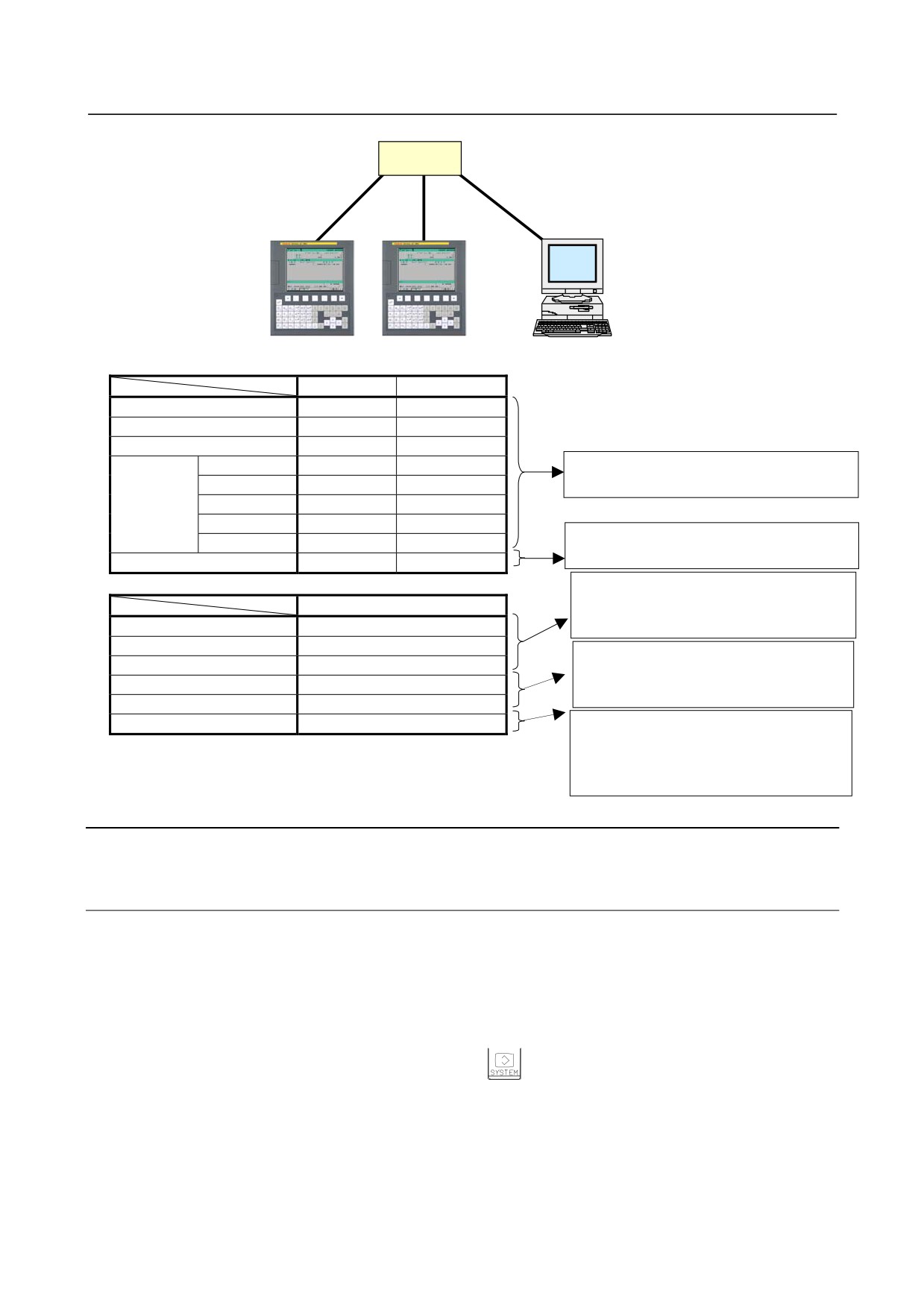
The following shows a setting example required for the FTP file transfer function to operate.
In this example, one personal computer is connected to two CNCs through the FTP file transfer function.
• On Personal Computer 1, the FTP server function operates.
• On CNC 1 and CNC 2, the FTP client operates as the FTP file transfer function.
- 284 -
B-64305EN/03
7.EMBEDDED ETHERNET FUNCTION
HUB
10BASE-T or
100BASE-TX
CNC 1
CNC 2
PC 1
CNC 1
CNC 2
IP address
192.168.0.100
192.168.0.101
Subnet mask
255.255.255.0
255.255.255.0
Router IP address
None
None
Connection
Port number
21
21
The Ethernet parameter screen is used for
host 1
IP address
192.168.0.200
192.168.0.200
setting.
User name
user
user
Password
user
user
Login DIR
None
None
The parameter screen is used for setting.
NC parameter No. 20
9
9
"Microsoft TCP/IP property" of the
PC 1
personal computer (Windows 2000 / XP /
IP address
192.168.0.200
Vista) is used for setting.
Subnet mask
255.255.255.0
"User acount of the personal computer
Default gateway
None
(Windows 2000 / XP / Vista) is used for
User name
user
setting.
Password
user
Login DIR
Default
"Internet service manager" of the
personal computer (Windows 2000 / XP)
is used for setting.
"FTP Publishing Service" (Windows
7.2.3
Setting Up the DNS/DHCP Function
The DHCP/DNS function is set up by using the COMMON screen (DETAIL) and NC parameters.
7.2.3.1 Setting up DNS
This subsection describes the procedure for setting up a DNS.
Procedure
1
Enable the DNS function, with reference to "Related NC Parameters," which will be seen later.
2
Set up the DNS server of the host computer.
3
Connect the host computer on which the DNS server is working (hereafter referred to as a DNS
server), reboot the CNC, then press function key
4
Press soft keys [EMBED] and [COMMON] in that order. The COMMON screen (DETAIL)
appears.
5
Enter the IP address of the DNS server in the corresponding DNS IP address field.
- 285 -
7.EMBEDDED ETHERNET FUNCTION
B-64305EN/03
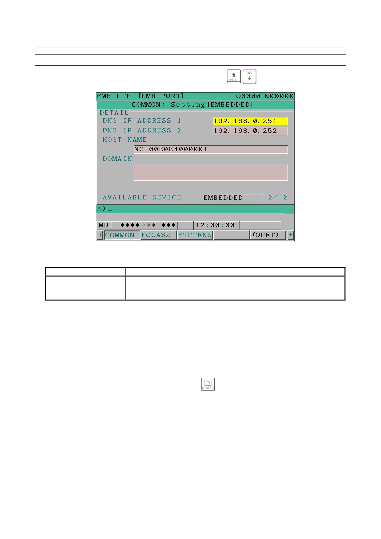
COMMON screen (DETAIL)
After pressing soft key [COMMON], press either page key
to call a desired COMMON
screen (DETAIL). Specify a DNS IP address.
COMMON screen (DETAIL)
Setting items
Item
Description
DNS IP ADDRESS 1, 2
Up to two DNS IP addresses can be specified.
The CNC searches for the DNS server using DNS IP addresses 1 and 2 in that
order.
7.2.3.2 Setting up DHCP
This subsection describes the procedure for setting up a DHCP.
Procedure
1
Enable the DHCP function, with reference to "Related NC Parameters," which will be seen later.
2
Set up the DHCP server of the host computer.
3
Connect the host computer on which the DHCP server is working (hereafter referred to as a DHCP
server), reboot the CNC, then press function key
4
Press soft keys [EMBED] and [COMMON] in that order. The COMMON screen appears.
5
If the DHCP function of the CNC has been enabled and if the DHCP server is connected
successfully, the DHCP server automatically specifies the following items.
-
IP ADDRESS
-
SUBNET MASK
-
ROUTER IP ADDRESS
-
DNS IP ADDRESS
-
DOMAIN
If the DHCP server cannot be connected, "DHCP ERROR" is displayed in each field.
6
If the DNS function has also been enabled and if the DHCP server and the DNS server work
together (if the DNS server supports dynamic DNS), enter a host name.
- 286 -
B-64305EN/03
7.EMBEDDED ETHERNET FUNCTION
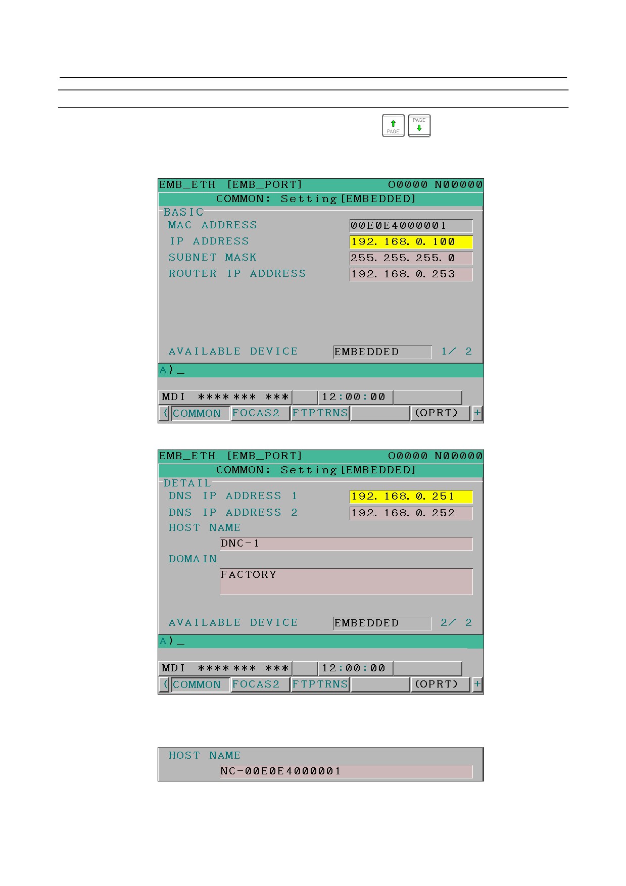
COMMON screen (basic and detail)
After pressing soft key
[COMMON], press either page key
to call a desired Ethernet
common setting screen (basic, detail).
If the DHCP server is connected successfully and if the setting data can be obtained, the screen is
displayed as shown below.
When the DHCP server is connected successfully (1st page)
When the DHCP server is connected successfully (2nd page)
If the host name is not specified, the CNC automatically assigns a host name in the
"NC-<MAC-address>" format.
Example of automatically assigned host name
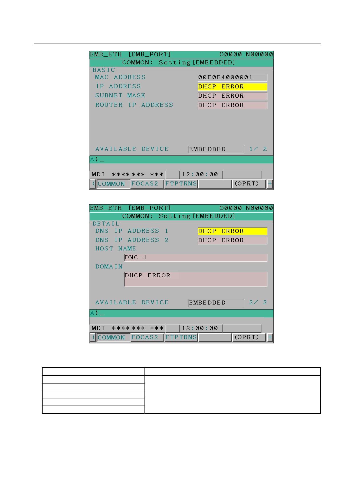
If the DHCP server cannot be connected, the screen is displayed as shown below.
- 287 -
7.EMBEDDED ETHERNET FUNCTION
B-64305EN/03
When the DHCP server cannot be connected (1st page)
When the DHCP server cannot be connected (2nd page)
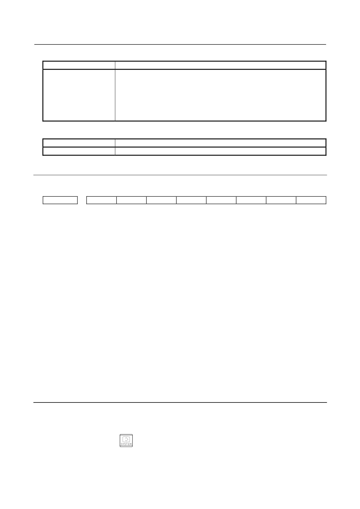
Check items
Item
Description
IP ADDRESS
If the DHCP server is connected successfully, the items obtained from
SUBNET MASK
the DHCP server are displayed.
ROUTER IP ADDRESS
If the DHCP server cannot be connected, "DHCP ERROR" is displayed.
DNS IP ADDRESS 1,2
DOMAIN
- 288 -
B-64305EN/03
7.EMBEDDED ETHERNET FUNCTION
Setting items
Item
Description
HOST NAME
Enter the host name of the CNC.
If a DHCP server and a DNS server work together, the DHCP server notifies the
DNS server of this host name.
If the host name is left blank, a host name is automatically assigned in the
"NC-<MAC-address>" format.
Example of automatically assigned host name:
NC-00E0E4000001
Display items
Item
Description
MAC ADDRESS
MAC address of embedded Ethernet
7.2.3.3 Related NC parameters
For embedded Ethernet port
#7
#6
#5
#4
#3
#2
#1
#0
14880
DHC
DNS
D1E
[Input type] Setting input
[Data type] Bit
# 3
D1E When the DHCP function is used:
0: The default parameters for the FOCAS2/Ethernet function are specified.
PORT NUMBER (TCP)
8193
PORT NUMBER (UDP)
0
TIME INTERVAL
0
1: The default parameters for CIMPLICITY i CELL are specified.
PORT NUMBER (TCP)
8193
PORT NUMBER (UDP)
8192
TIME INTERVAL
50
# 5
DNS The DNS function is:
0: Not used.
1: Used.
# 6 DHC The DHCP function is:
0: Not used.
1: Used.
A change in these parameters becomes effective after the power is turned off and on or after
the
embedded Ethernet function is restarted.
7.2.4
Backing up and Restoring Communication Parameters
This section describes how to back up the embedded Ethernet communication parameters to a memory
card and to restore them from the memory card.
1.
Press the function key
2.
The soft keys [EMBED] and [PCMCIA] appear.
(If they do not appear, press the continuous menu
key.)
- 289 -
7.EMBEDDED ETHERNET FUNCTION
B-64305EN/03
3.
When the soft key [EMBED] or [PCMCIA] is pressed, the Ethernet Setting screen, respectively, for
the embedded Ethernet port or the PCMCIA Ethernet card appears.
4.
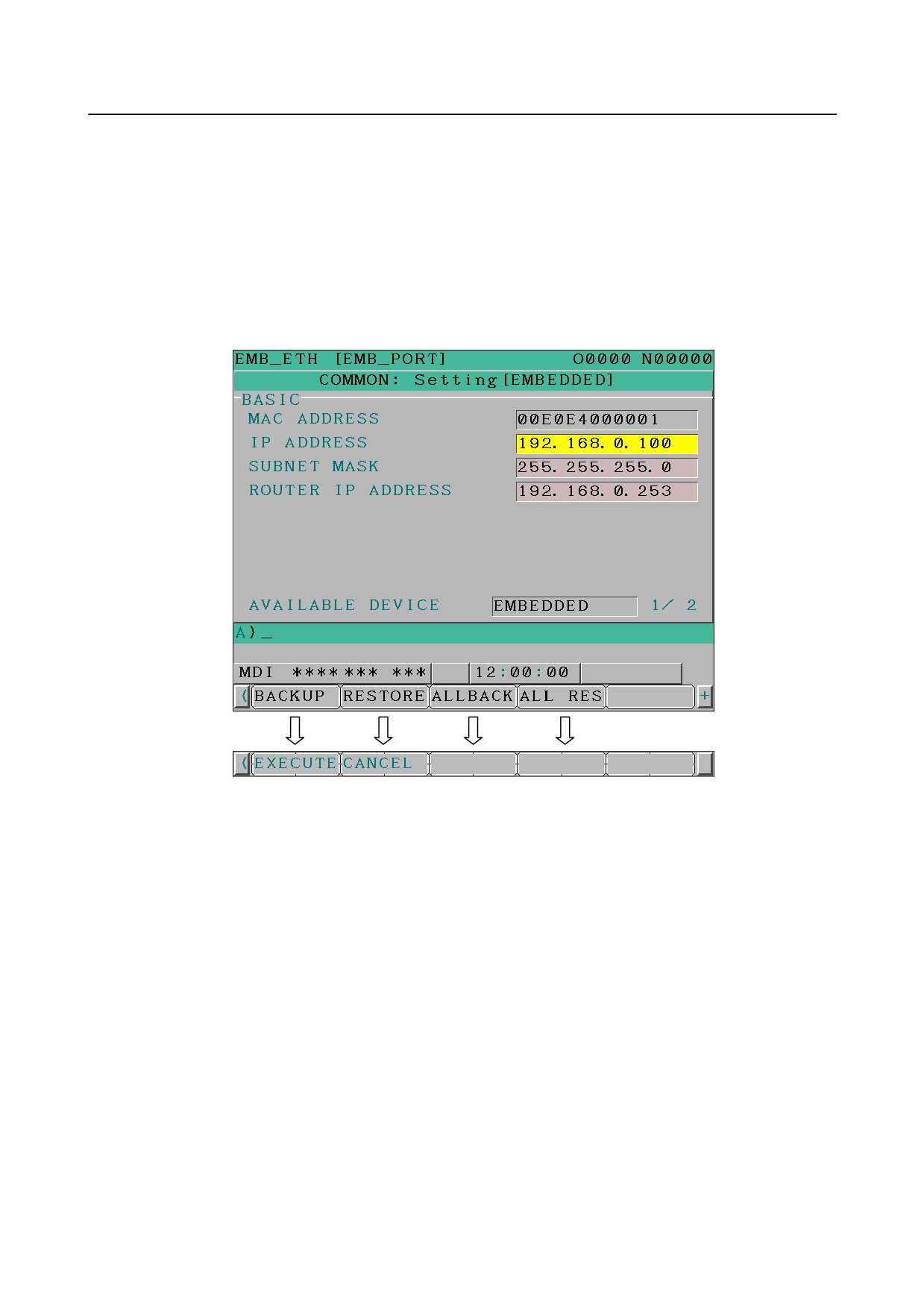
Once the soft keys [COMMON] and [(OPRT)] are pressed, pressing the soft key [+] displays the soft
keys
[BACKUP], [RESTORE], [ALLBACK], and [ALL RES] for backing up or restoring
communication parameters as shown below.
5.
Pressing the soft key [BACKUP], [RESTORE], [ALLBACK], or [ALL RES] displays the soft keys
[EXECUTE] and [CANCEL].
6.
Once the name of a file to be backed up or restored is entered into a key-in buffer, pressing the soft
key [EXECUTE] starts the respective operation.
"EXECUTING" blinks while backup or restoration is in progress.
BACKUP
The embedded Ethernet communication parameters are saved from the SRAM of the CNC main unit to
the memory card.
If a file name is specified in the key-in buffer, the specified file name is used when the parameters are
saved to the memory card. If no file name is specified, the file name “EMBETHER.MEM” is used.
RESTORE
The embedded Ethernet communication parameters are read from the memory card and saved to the
SRAM of the CNC main unit.
If a file name is specified in the key-in buffer, the specified file name is used when the parameters are
read from the memory card. If no file name is specified, the file name “EMBETHER.MEM” is used.
ALLBACK
All valid embedded Ethernet, Fast Ethernet/Fast Data server, PROFIBUS-DP master/slave, DeviceNet
master/slave, and FL-net communication parameters are saved from the SRAM of the CNC main unit to
the memory card.
If a file name is specified in the key-in buffer, the file name is used when the parameters are saved. If no
file name is specified, the file name “NETWORK.MEM” is used.
- 290 -

B-64305EN/03
7.EMBEDDED ETHERNET FUNCTION
ALL RES
All valid embedded Ethernet, Fast Ethernet/Fast Data server, PROFIBUS-DP master/slave, DeviceNet
master/slave, and FL-net communication parameters are read from the memory card and saved to the
SRAM of the CNC main unit.
However, if a communication function related to a valid communication parameter is disabled in the CNC,
that parameter is not saved to the SRAM.
If a file name is specified in the key-in buffer, the specified file name is used when the parameters are
read from the memory card. If no file name is specified, the file name “NETWORK.MEM” is used.
NOTE
1 Communication parameter backup and restoration are usable only in the MDI
mode and at an emergency stop.
2 Performing communication parameter restoration leads to an alarm condition
that requests to turn off the power.
3 When communication parameters are backed up or restored, the memory card is
always used no matter what the external input/output device number (NC
parameter No. 20) is.
7.3
SWITCHING BETWEEN THE EMBEDDED ETHERNET
DEVICES
There are two types of embedded Ethernet devices: the embedded Ethernet port and PCMCIA Ethernet
card.
Screen operation is required to switch between these two types of devices.
Procedure
1
Press the function key
2
Soft keys [EMBED] and [PCMCIA] appear.
(When there is no soft keys, press the continue key.)
3
Press soft key [EMBED] or [PCMCIA], press soft key [COMMON], and then press [(OPRT)] to
display soft key [EMB/PCM].
4
Pressing soft key [EMB/PCM] switches between enabled devices.
•
If you want to execute the switchover, press soft key [EXECUTE].
•
If you do not want to execute the switchover, press soft key [CANCEL].
5
The valid devices are switched each time Step 4 is performed.
NOTE
Information on a switched device is stored in nonvolatile memory.
On the next power-on, the device last selected can be used as is.
7.4
EMBEDDED ETHERNET OPERATIONS
7.4.1
FTP File Transfer Function
The operation of the FTP file transfer function is described below.
Host file list display
A list of the files held on the host computer is displayed.
- 291 -
7.EMBEDDED ETHERNET FUNCTION
B-64305EN/03
Procedure
1
Press the function key
2
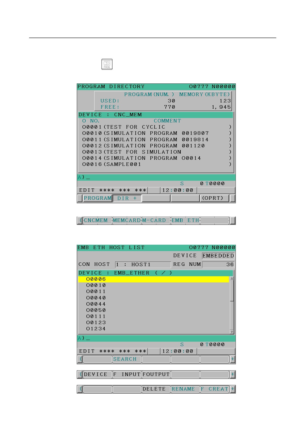
Press soft key [DIR+]. The program folder screen appears. (If the soft key does not appear, press the
continuous menu key.)
3
Press soft keys [(OPRT)] and [DEVICE] in that order. The soft keys for selectable devices appear.
4
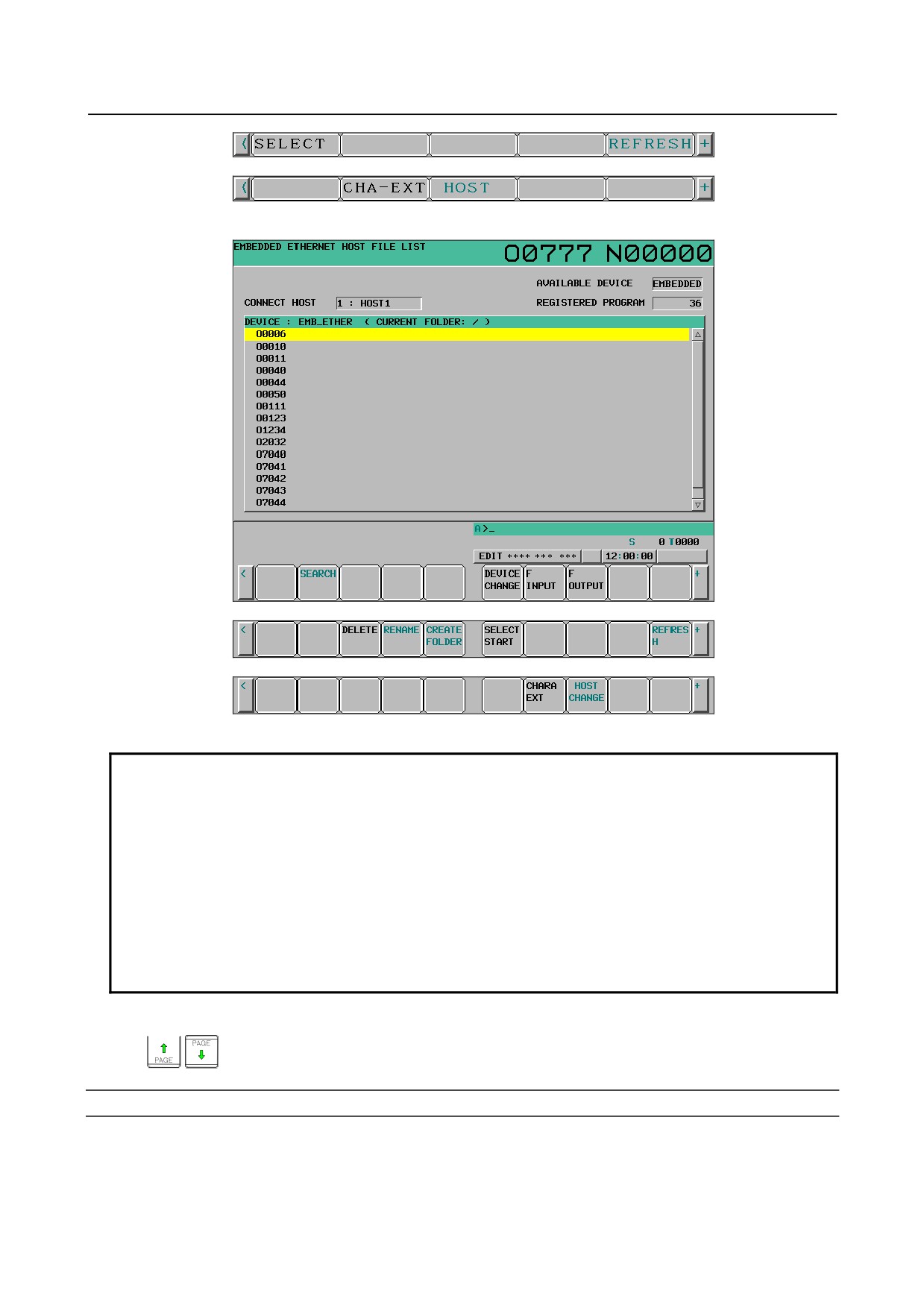
Pressing soft key [EMB ETH] displays the Embedded Ethernet host file list screen, on which a list
of files in the host computer connected with the embedded Ethernet port is displayed.
- 292 -
B-64305EN/03
7.EMBEDDED ETHERNET FUNCTION
Embedded Ethernet host file list screen (8.4-inch LCD)
Embedded Ethernet host file list screen (10.4-inch LCD)
NOTE
When using the FTP file transfer function, check that the valid device is the
embedded Ethernet port.
The two conditions below determine a connection destination on the host file list
screen:
(1) Check that the valid device is the embedded Ethernet port. To select a
valid device, use soft key [EMB/PCM] on the Ethernet Setting screen.
(2) A host computer can be selected from connection destinations 1, 2, and 3.
A computer to be connected is selected using the operation procedure
described in Subsection 7.2.2.1, "Operation on the FTP file transfer setting
screen" or “HOST CHANGE” explained later.
5
When a list of files is larger than one page, the screen display can be switched using the page keys
Display item
DEVICE (AVAILABLE DEVICE)
The currently selected device is displayed.
- 293 -

7.EMBEDDED ETHERNET FUNCTION
B-64305EN/03
CON HOST (CONNECT HOST)
Number of the currently connected host of the host computer
REG NUM (REGISTERED PROGRAM)
The number of files in the current folder.
DEVICE
Current device. When the embedded Ethernet host file list is selected, “EMB_ETHER” is displayed.
CURRENT FOLDER
Current work folder in the host computer
FILE LIST
Information of the files and folders in the host computer
Operation list
DEVICE (DEVICE CHANGE)
Enables a device to be selected from the program folder screen.
To select the embedded Ethernet host
file list, press soft key [EMB ETH].
DIR +
Switches between the outline and detailed file lists.
F CREAT (CREATE FOLDER)
Create a subfolder in the current work folder in the host computer.
DELETE
Deletes a file or folder in the host computer.
RENAME
Renames a file or folder in the host computer.
HOST (HOST CHANGE)
Changes the connected host computer.
SEARCH
Searches for a file through the current folder in the host computer.
REFRESH
Updates the information displayed on the embedded Ethernet host file list screen.
F INPUT
Transfers a program from the host computer to the CNC memory.
F OUTPUT
Transfers a program from the CNC memory to the host computer.
NOTE
The character strings enclosed in parentheses are those displayed when the
10.4-inch LCD unit is used.
- 294 -
B-64305EN/03
7.EMBEDDED ETHERNET FUNCTION
7.4.1.1 Displaying and operating the file list
DETAIL ON, DETAIL OFF
Displays can be switched between outline and detailed file lists.
Either the outline or detailed file list display is selected each time soft key [DIR+] is pressed.
The outline file list display contains only file names, while the detailed file list display contains file sizes,
creation dates, and other file information as well file names.
NOTE
1 The items displayed in the detailed list depend on the FTP server setting on the
host computer.
2 When files in the detailed file list are operated on, information displayed at the
right edge of the screen is treated as a file name. Therefore, it is likely that files
may not be operated on properly depending on displays or file names.
If this is
the case, use the outline file list display.
REFRESH
Update the contents of the file list.
Pressing soft key [REFRESH] causes the file list contents to be updated.
Moving a folder
Move a folder.
1
Select a folder you want to move using cursor keys
and
2
Press MDI key
CREATE FOLDER
Create a new folder.
1
Move to a folder in which you want to create a new folder.
2
Key in a folder name.
3
Press soft key [F CREAT] ([CREATE FOLDER]).
DELETE
Delete a file or folder.
1
Select a file or folder you want to delete using cursor keys
and
2
Press soft key [DELETE].
•
To execute the deletion, press soft key [EXEC].
•
To cancel the deletion, soft key [CANCEL].
DELETE (multiple files)
Delete multiple files at a time.
1
Press soft key [SELECT] ([SELECT START]).
2
Select a file or folder you want to delete using cursor keys
and
3
Press soft key [SELECT].
The selected file is highlighted.
Repeat steps 2 and 3 for each file you want to delete.
4
Press soft key [DELETE].
- 295 -
7.EMBEDDED ETHERNET FUNCTION
B-64305EN/03
-
To execute the deletion, press soft key [EXEC].
-
To cancel the deletion, soft key [CANCEL].
NOTE
1 Up to 10 files can be selected at a time.
2 Only files can be specified. If folders are specified, an error is reported when an
attempt is made to delete the folders.
RENAME
Rename a file or folder.
1
Select a file or folder you want to rename using cursor keys
and
2
Enter a new file or folder name.
3
Press soft key [RENAME].
SEARCH
Search for a file or folder through the current work folder. The file or folder found is displayed at the
top of the file list.
1
Key in a file or folder name you want to search for.
2
Press soft key [SEARCH].
HOST CHANGE
Change the connected host computer.
1
Press soft key [HOST] ([HOST CHANGE]).
The connected host number changes from 1 to 2 to 3, then back to 1.
7.4.1.2 Transferring programs
How programs are transferred between the host computer and CNC is explained below.
NOTE
1 Inputting or outputting programs with the embedded Ethernet host requires
setting NC parameter No. 20 with 9.
2 If an error occurs, check its cause on the Ethernet log screen.
Inputting programs
The following procedure can be used to transfer programs from the host computer to the CNC memory.
1
Press soft key [F INPUT].
2
Select a program in the host computer.
In the host computer, place the cursor on the file you want to input and press soft key [F GET], or
key in the file name.
3
Press soft key [F NAME].
4
If you want to rename a program when inputting it, key in the program number and press soft key [O
SET].
5
Press soft key [EXEC].
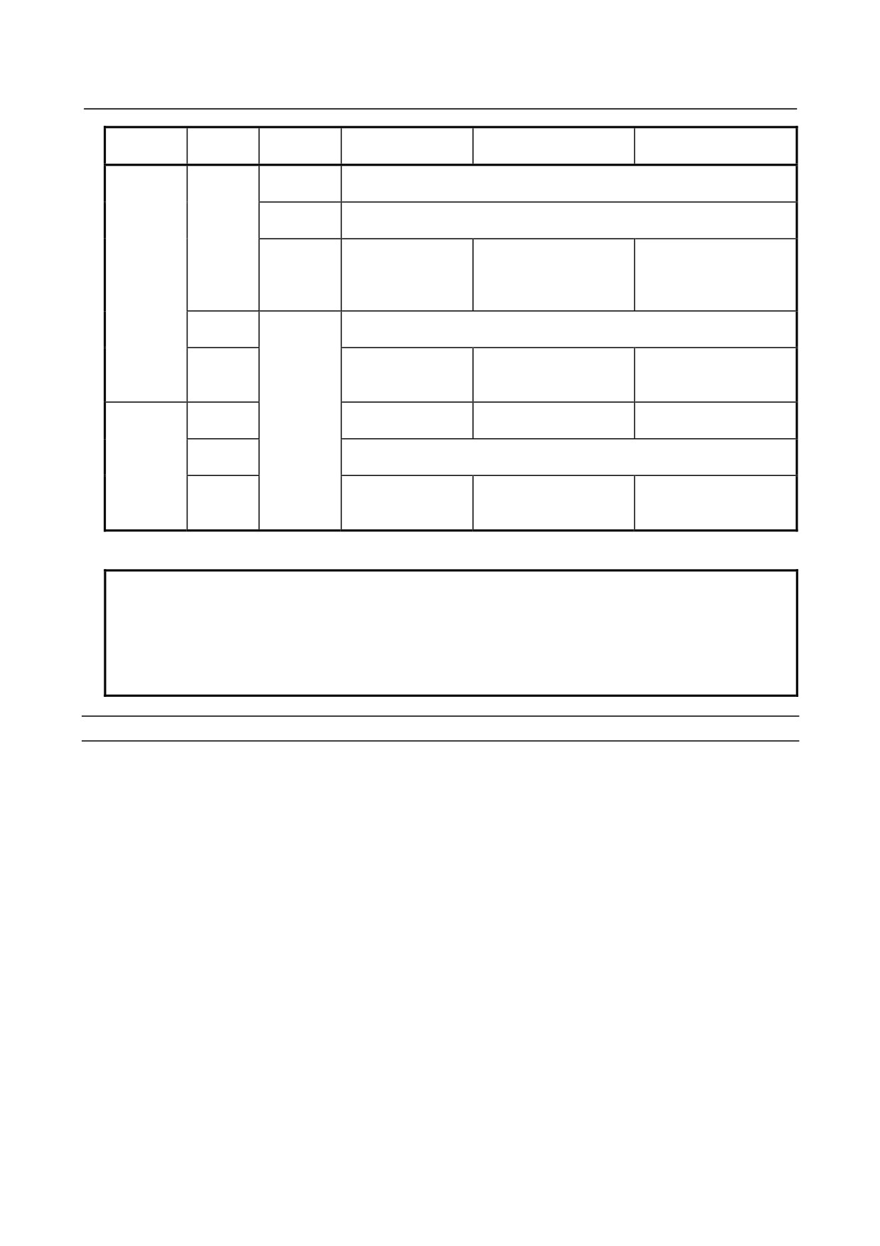
The following table summarizes what operation occurs when the input file name [F NAME] and input
program number [O SET] are omitted.
- 296 -
B-64305EN/03
7.EMBEDDED ETHERNET FUNCTION
Key input
[F NAME]
[O SET]
Input file name
Input program
Input program No.
buffer
Warning message “NO PROGRAM SELECTED” is displayed, and nothing
–
is input.
Other than
Warning message “THE WRONG DATA IS USED” is displayed, and
Oxxxx
nothing is input.
–
Continuous program
File name set in the
All programs in the input
numbers starting at one
Oxxxx
key input buffer
–
file
(xxxx) set in the key
(NOTE)
input buffer
Warning message “NO PROGRAM SELECTED” is displayed, and nothing
-9999
is input.
Same file name as
Continuous program
All programs in the input
O
program No. set by
numbers starting at one
file
[O SET] (NOTE)
set by [O SET]
File name set by [F
All programs in a file
Program No. used when
–
No relation
NAME]
specified by [F NAME]
the program was saved
Warning message “THE WRONG DATA IS USED” is displayed, and
-9999
O
nothing is input.
Continuous program
File name set by [F
All programs in the file
O
numbers starting at one
NAME]
specified by [F NAME]
set by [O SET]
O: Specified
- : Not specified
NOTE
The input file name consists of “O” followed by a 4-digit number.
If program input is executed by specifying program No. 1, for example, a file
whose file name is “O0001” is input.
If this operation is performed for path 2, the file name is suffixed with the file
extension “P-2” (for this example, “O0001.P-2”).
Outputting programs
The following procedure can be used to transfer programs from the CNC memory to the host computer.
1
Press soft key [FOUTPUT].
2
Select a program in the CNC.
Key in the program No. of the program to be output.
3
Press soft key [O SET].
4
If you want to rename a program when outputting it, key in the file name and press soft key [F
NAME].
5
Press soft key [EXEC].
The following table summarizes what operation occurs when the output file name [F NAME] and output
program number [O SET] are omitted.
- 297 -
7.EMBEDDED ETHERNET FUNCTION
B-64305EN/03
Key input
[F NAME]
[O SET]
Output file name
Output program
buffer
Currently selected main program
Currently selected main program
–
name (NOTE 1 and NOTE 2)
(NOTE 1)
Other than
Warning message “THE WRONG DATA IS USED” is displayed, and
–
Oxxxx
nothing is output.
Program name set in the key
Program in the CNC memory set in the
–
Oxxxx
input buffer (NOTE 2)
key input butter
O-9999
ALL-PROG.TXT (NOTE 3)
All programs in the CNC memory
-9999
Same file name as program No.
Program in the CNC memory set by [O
O
set by [O SET] (NOTE 2)
SET]
Currently selected main program
–
No relation
(NOTE 1)
O
-9999
File name set by [F NAME]
All programs in the CNC memory
Program in the CNC memory set by [O
O
SET]
O : Specified
- : Not specified
NOTE
1 If a file is undergoing background editing, it is output.
2 The output file name consists of “O” followed by a 4-digit number.
If a program whose program No. is 1 is output, for example, it is output under the
file name “O0001” to the host computer.
If this operation is performed for path 2, the file name is suffixed with the file
extension “P-2” (for this example, “O0001.P-2”).
3 If this operation is performed for path 2, the file name “ALL-PROG.P-2” is used.
7.4.1.3 Inputting special characters
Using bits 4 (SI1) and 5 (SI2) of NC parameter No. 13115 enables special characters and lowercase letters,
which are not available on the MDI keypad, to be entered.
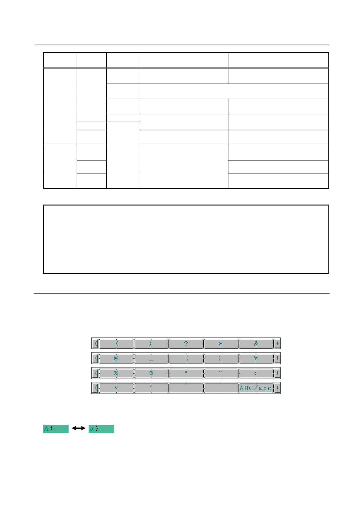
Setting this NC parameter displays soft key [CHA-EXT]([CHARA EXT]). Pressing this soft key
displays the following soft keys:
Pressing soft key [ABC/abc] switches between uppercase and lowercase characters for input. Which
case can be currently input is indicated in the key input field.
Uppercase
Lowercase
letter input
letter input
- 298 -
B-64305EN/03
7.EMBEDDED ETHERNET FUNCTION
Related NC parameters
#7
#6
#5
#4
#3
#2
#1
#0
13115
SI2
SI1
[Input type] Parameter input
[Data type] Bit
# 4
SI1 Soft key input of the characters shown below and switching between the uppercase and
lowercase input modes by a soft key are:
0: Disabled.
1: Enabled.
< > ¥ % $ ! ~ : " '
# 5
SI2 Soft key input of the characters shown below and switching between the uppercase and
lowercase input modes by a soft key are:
0: Disabled.
1: Enabled.
( ) ? * & @ _
7.5
RESTART OF THE EMBEDDED ETHERNET
Communication using the embedded Ethernet can be restarted.
Procedure
1
Press the function key
2
Soft keys [EMBED] and [PCMCIA] appear.
(When there is no soft keys, press the continue key.)
3
Press soft key [EMBED] or [PCMCIA], press soft key [COMMON], and then press [(OPRT)] to
display soft key [RESTART].
4
Pressing soft key [RESTART] resets embedded Ethernet communication and then restarts it.
NOTE
1 Pressing soft key [RESTART] forcibly interrupts communication even when it is
in progress.
2 This function makes a restart by software. An actual restart may be impossible
under some conditions.
7.6
MAINTENANCE SCREEN FOR EMBEDDED ETHERNET
FUNCTION
With the embedded Ethernet function, a dedicated maintenance screen is available.
The maintenance screen enables operations to be checked when the embedded Ethernet function operates
abnormally.
Displaying and operating the PING screen
Procedure
1
Press the function key
2
Soft keys [EMBED] and [PCMCIA] appear.
- 299 -
7.EMBEDDED ETHERNET FUNCTION
B-64305EN/03
(When there is no soft keys, press the continue key.)
3
By pressing the [EMBED] soft key, the Ethernet Setting screen for the embedded Ethernet is
displayed.
By pressing the [PCMCIA] soft key, the Ethernet Setting screen for the PCMCIA Ethernet card can
be set.
4
Press soft key [PING] and then press [(OPRT)].
5
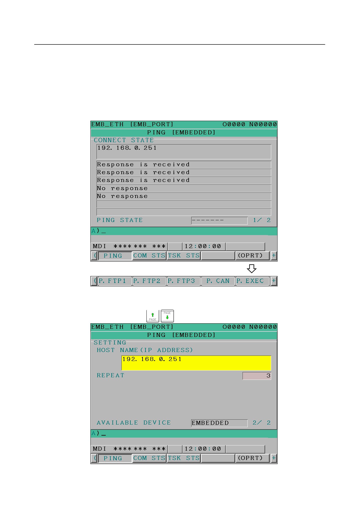
To send the PING command to connection destination 1 for FTP file transfer, press soft key
[P.FTP1]. Similarly, to send the PING command to connection destination 2 or 3, press [P.FTP2] or
[P.FTP3], respectively.
PING connection status screen
6
To send the PING command to the desired destination, enter the address of the destination on the
PING setting screen. (Page keys
are used for switching.)
PING connection setting screen
- 300 -
B-64305EN/03
7.EMBEDDED ETHERNET FUNCTION
7
After entering the address and the repeat count, press the soft key [P.EXEC]. The specified number
of PING commands are sent to the specified destination.
8
To cancel the PING command currently being sent, press soft key [P.CAN].
Displaying Communication status screen
Procedure
1
Press the function key
2
Soft keys [EMBED] and [PCMCIA] appear.
(When there is no soft keys, press the continue key.)
3
By pressing the [EMBED] soft key, the Ethernet Setting screen for the embedded Ethernet is
displayed.
By pressing the [PCMCIA] soft key, the Ethernet Setting screen for the PCMCIA Ethernet card can
be set.
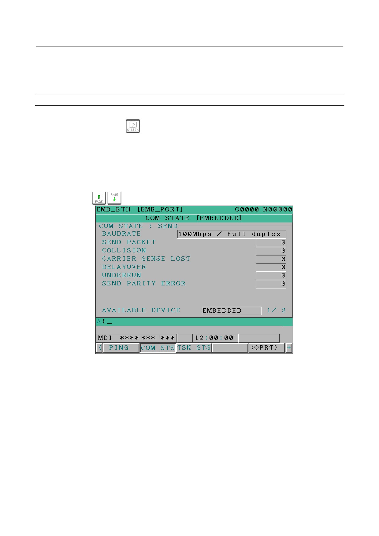
4
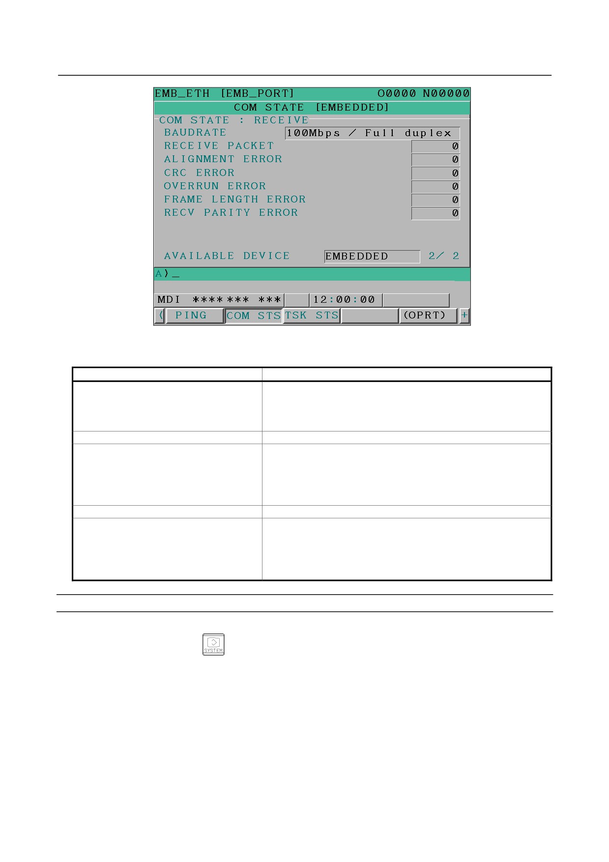
To display the communication status of the embedded Ethernet, press soft key [COM STS].
Page keys
can be used to switch between the sending state and the receiving state.
Communication status screen (1st page)
- 301 -
7.EMBEDDED ETHERNET FUNCTION
B-64305EN/03
Communication status screen (2nd page)
Display items
Display item
Explanation
BAUDRATE
Indicates the communication speed and communication mode.
Communication speed:
100 or 10 Mbps
Communication mode:
Full or half duplex
--------: Not connected to HUB
SEND PACKET
Indicates the number of packets sent.
COLLISION
Indicate the number of errors detected during packet transmission.
CARRIER SENSE LOST
DELAYOVER
UNDERRUN
SEND PARITY ERROR
RECEIVE PACKET
Indicates the number of packets received.
ALIGNMENT ERROR
Indicate the number of errors detected during packet reception.
CRC ERROR
OVERRUN ERROR
FRAME LENGTH ERROR
RECV PARITY ERROR
Displaying Task status screen
Procedure
1
Press the function key
2
Soft keys [EMBED] and [PCMCIA] appear.
(When there is no soft keys, press the continue key.)
3 To display the Ethernet Setting screen for the embedded Ethernet port or the PCMCIA Ethernet card,
press soft key [EMBED] or [PCMCIA], respectively.
4
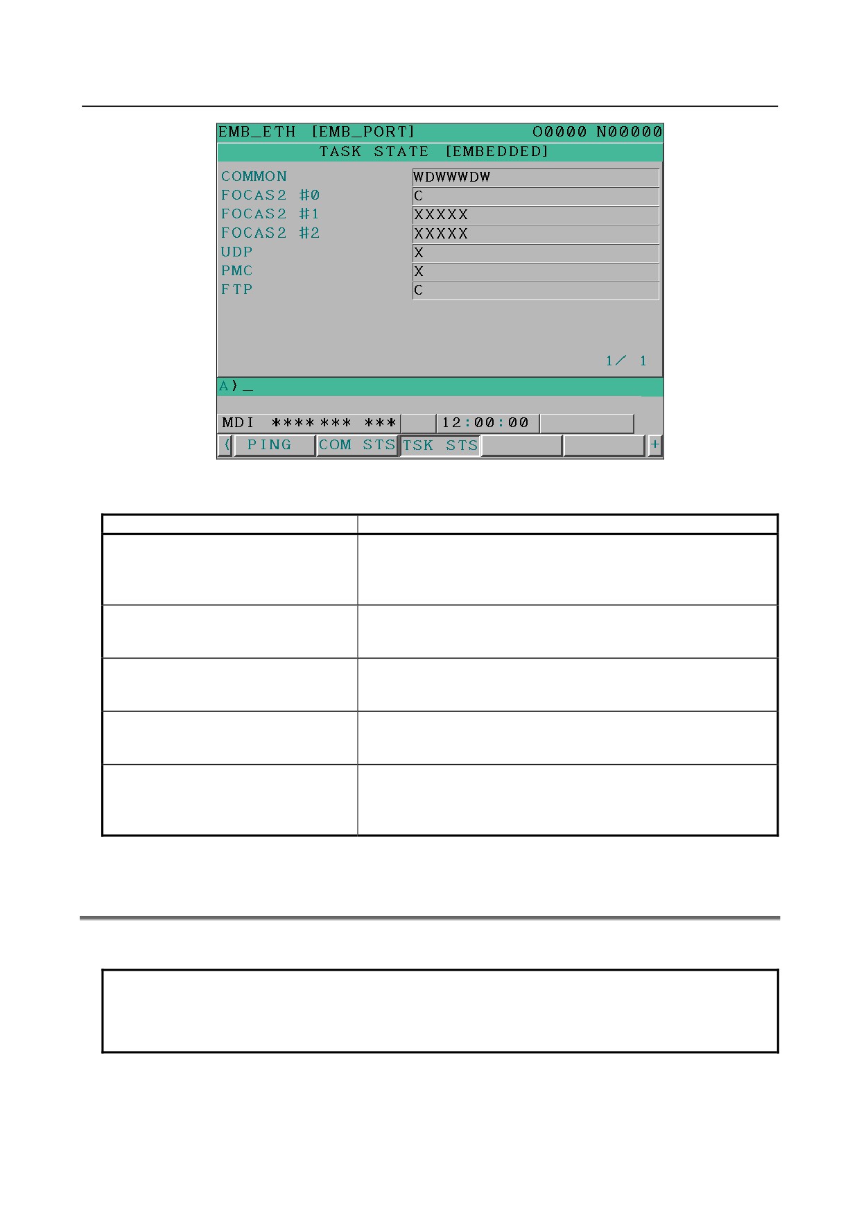
Pressing soft key [TSK STS] causes the task status of the embedded Ethernet function to be
displayed.
- 302 -
B-64305EN/03
7.EMBEDDED ETHERNET FUNCTION
Task status screen
The following symbols are used.
Symbol and meaning
FOCAS2 #0
C: Waiting for a connection from the host
(FOCAS2/Ethernet)
W: Data processing in progress (1)
D: Data processing in progress (2)
N: FOCAS2 out of service
FOCAS2 #1,#2
W: Data processing in progress (1)
(FOCAS2/Ethernet)
D: Data processing in progress (2)
X: Not yet executed
PMC
W: Data processing in progress (1)
(FANUC LADDER-III)
D: Data processing in progress (2)
X: Not yet executed
UDP
W: Data processing in progress (1)
(CIMPLICITY iCELL)
D: Data processing in progress (2)
X: Not yet executed
FTP
C: Execution wait
(FTP file transfer function)
W: Data processing in progress (1)
D: Data processing in progress (2)
X: Not yet executed
7.7
LOG SCREEN OF THE EMBEDDED ETHERNET
FUNCTION
This screen displays the log of the embedded Ethernet function.
NOTE
If alarm SR2032, “EMBEDDED ETHERNET/DATA SERVER ERROR” is issued
during data transfer using the embedded Ethernet function, check the error
details on the log screen of the embedded Ethernet function.
- 303 -
7.EMBEDDED ETHERNET FUNCTION
B-64305EN/03
Displaying the log screen
Procedure
1
Press the function key
2
To display the log screen for the embedded Ethernet port or PCMCIA Ethernet card, press soft key
[EMB LOG] or [PCM LOG], respectively. (When there is no soft keys, press the continue key.)
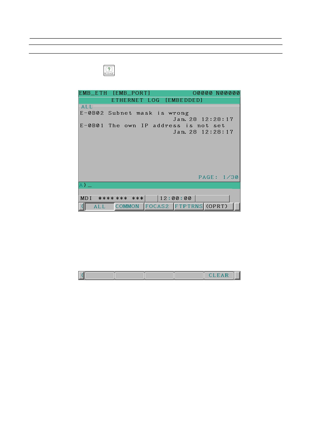
LOG screen
The newest error log appears at the top of the screen. The date and time when an error occurred are
displayed at the right end of the line. The format of date and time data is “MMM.DD hh:mm:ss” where
MMM represents a month, DD represents a day, hh represents hours, mm represents minutes, and ss
represents seconds.
The date and time of the upper item shown above is January 28, 12:28:17.
To clear the log, press soft keys [(OPRT)] and [CLEAR] in that order.
The log for each function can be displayed by using soft keys on the embedded Ethernet log screen.
(1) Soft key [ALL]
Displays all log related to the embedded Ethernet.
(2) Soft key [COMMON]
Displays the log related to the parameter settings of the embedded Ethernet function and the basic
communication function.
(3) Soft key [FOCAS2]
Displays the log related to the FOCAS2/Ethernet function.
(4) Soft key [FTPTRNS]
Displays the log related to FTP file transfer.
- 304 -

B-64305EN/03
7.EMBEDDED ETHERNET FUNCTION
Error and message
Error No.
Log message
Description and necessary action
E-0118
Error occurred while wait for FOCAS2
A communication error has occurred because of any of
E-0119
pdu
the following:
→ The network quality has been lowered to such a level
that data cannot be received from a PC at the other
end. The communication channel has been logically
shut down.
→ Software running on a PC at the other end has
logically shut down the communication channel.
→ The Ethernet cable has been disconnected.
E-011A
All communication paths are busy
All the FOCAS2/Ethernet communication channels are
busy.
E-0200
Received message from FTP server
A message sent by the FTP server is directly displayed.
E-0202
Connection failed with FTP server
Software of the FTP server may not be running. Start
the software of the FTP server.
E-0207
The router is not found
The specified IP address of the router may be wrong.
Alternatively, the router may be turned off. Check
whether the IP address of the router has been correctly
specified and whether the router is turned on.
E-0208
The FTP server is not found
The specified IP address of the FTP server may be
wrong. Alternatively, the FTP server may be turned off.
Check whether the IP address of the FTP server has
been correctly specified and whether the FTP server is
turned on.
E-020B
Cannot login into FTP server
Check whether a correct user name and password are
specified when logging into the FTP server.
E-020C
The parameters of FTP server are
Check whether a correct user name and password are
wrong
specified when logging into the FTP server.
E-020D
Changing a work folder of host failed
Check the work folder logging into the FTP server.
E-041A
Frame transmission failed (TCP)
A communication error has occurred because of any of
the following:
→ The network quality has been lowered to such a level
that data cannot be received from a PC at the other
end. The communication channel has been logically
shut down.
→ Software running on a PC at the other end has
logically shut down the communication channel.
→ The Ethernet cable has been disconnected.
E-0901
Cannot read MAC address
The MAC address is not written in the hardware.
Alternatively, the hardware has been damaged.
E-0A06
Network is too busy
An excessive amount of data is flowing over the network.
One possible solution is to divide the network.
E-0B00
The own IP address is wrong
Specify a correct IP address in the designated format.
E-0B01
The own IP address is not set
Specify an IP address.
E-0B02
Subnet mask is wrong
Specify a correct subnet mask in the designated format.
E-0B03
Subnet mask is not set
Specify a subnet mask.
E-0B04
Router IP address is wrong
There may be class disagreement between the IP
address of the local node and the IP address of the
router.
E-0B05
IP address of DNS server is wrong
There may be class disagreement between the IP
address of the local node and the IP address of the DNS
server.
E-0B06
The own host name is wrong
Check whether a correct host name is specified.
E-0B07
The own domain name is wrong
Check whether a correct domain name is specified.
- 305 -

7.EMBEDDED ETHERNET FUNCTION
B-64305EN/03
Error No.
Log message
Description and necessary action
E-0B08
TCP port number is wrong
A value beyond the permissible setting range may be
specified.
E-0B09
UDP port number is wrong
A value beyond the permissible setting range may be
specified.
E-0B0B
IP address of remote FTP server is
Specify a correct IP address in the designated format.
wrong
E-0B0B
IP address of remote FTP server is
Specify a correct IP address in the designated format.
wrong
E-0B0C
Port No of a remote FTP server is
A value beyond the permissible setting range may be
wrong
specified.
E-0B0D
User name of remote FTP server is
The specified user name may contain a prohibited
wrong
character.
E-0B0E
Password of remote FTP server is
The specified password may contain a prohibited
wrong
character.
E-0B0F
Login folder of remote FTP srv is wrong
The specified log-in folder name may contain a prohibited
character.
E-0B18
Cannot set because DHCP is available
To allow a set-up, disable the DHCP client function.
E-0B19
Embedded Ethernet hardware isn't
The software or hardware of embedded Ethernet function
E-0B1A
found
cannot be recognized. Check whether the software has
been incorporated. Check whether the hardware is
sound.
E-XXXX
(No message)
An internal error has occurred.
Make a notification of the error number.
- 306 -

B-64305EN/03
8.DIGITAL SERVO
8 DIGITAL SERVO
This chapter describes servo tuning screen required for maintenance of digital servo and adjustment of
reference position.
8.1 INITIAL SETTING SERVO PARAMETERS
307
8.2 FSSB DISPLAY AND SETTING SCREEN
316
8.3 SERVO TUNING SCREEN
322
8.4 ADJUSTING REFERENCE POSITION (DOG METHOD)
328
8.5 DOGLESS REFERENCE POSITION SETTING
330
8.6 αi SERVO WARNING INTERFACE
332
8.7 αi SERVO INFORMATION SCREEN
333
8.1
INITIAL SETTING SERVO PARAMETERS
This section describes how to set initial servo parameters, which is used for field adjustment of machine
tool.
1.
Turn on power at the emergency stop condition.
2.
Set parameters for displaying the servo setting screen and servo tuning screen.
#7
#6
#5
#4
#3
#2
#1
#0
3111
SVS
[Input type] Setting input
[Data type] Bit path
#0 SVS Servo setting screen or servo tuning screen is:
0: Not displayed.
1: Displayed.
3.
Set the parameter for the display format of the servo setting screen as required.
#7
#6
#5
#4
#3
#2
#1
#0
13117
SVO
[Input type] Parameter input
[Data type] Bit
#2 SVO On the servo setting screen,
0: Two screens, machine constant input screen and parameter
input
screen, are
displayed.
1: Only the parameter input screen is displayed.
Remark
When bit 2 (SVO) of parameter No. 13117 is set to 0, after displaying the servo setting screen,
press soft key [(OPRT)], continuous menu key [+], and soft key [SWITCH] to display the
parameter input screen.
When bit 2 (SVO) of parameter No. 13117 is set to 1, the parameter input screen is displayed
directly by performing the procedure for displaying the servo setting screen.
This section describes operations using the parameter input screen of the servo setting screen.
Therefore, setting this parameter makes operations described in this section easy.
- 307 -
8.DIGITAL SERVO
B-64305EN/03
4.
Turn off the power once then turn it on again.
5.
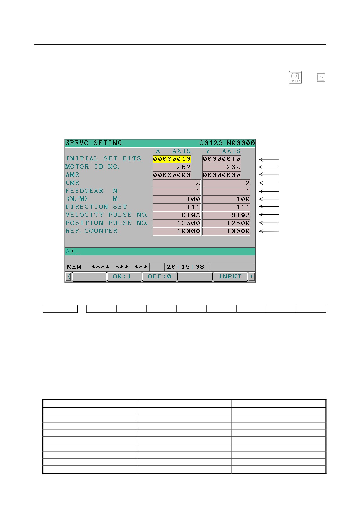
Display the servo parameter setting screen by the following operation: Function key
→
→ [SV.SET].
When bit 2 (SVO) of parameter No. 13117 described above is set to 0, also press soft key [(OPRT)],
continuous menu key [+], and soft key [SWITCH] to display the parameter input screen.
6.
Input data required for initial setting using the cursor and page key.
Parameter No.2000
Parameter No.2020
Parameter No.2001
Parameter No.1820
Parameter No.2084
Parameter No.2085
Parameter No.2022
Parameter No.2023
Parameter No.2024
Parameter No.1821
(1) Initial set bit
#7
#6
#5
#4
#3
#2
#1
#0
2000
DGPRM
PLC01
#0 PLC01 0: Values of parameters Nos. 2023 and 2024 are used as they are:
1 : Values of parameters Nos. 2023 and 2024 are multiplied by 10.
#1 DGPRM 0: Initial setting of digital servo parameter is done.
1: Initial setting of digital servo parameter is not done.
(2) Motor ID No.
Select the motor type No. of a servo motor to be used from the following table according to a motor
model and specification (four digits in the middle part of “A06B-xxxx-Bxxx).
Table 8.1 (a) αiS series servo motor
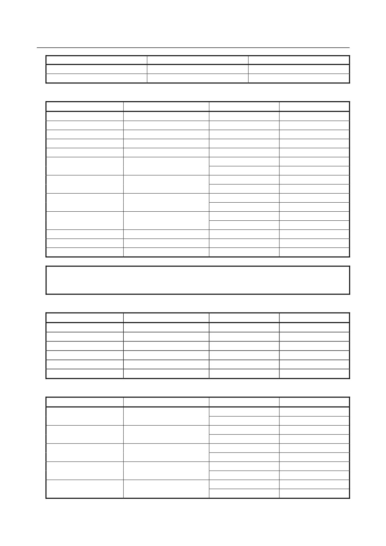
Motor model
Motor specification
Motor type No.
αiS 2 /5000
0212
262
αiS 2 /6000
0218
284
αiS 4 /5000
0215
265
αiS 8 /4000
0235
285
αiS 8 /6000
0232
290
αiS 12 /4000
0238
288
αiS 22 /4000
0265
315
αiS 22 /6000
0262
452
αiS 30 /4000
0268
318
- 308 -

B-64305EN/03
8.DIGITAL SERVO
Motor model
Motor specification
Motor type No.
αiS 40 /4000
0272
322
αiS 50 /3000
0275-Bx0x
324
αiS 50 /3000 FAN
0275-Bx1x
325
αiS 100 /2500
0285-Bx0x
335
αiS 100 /2500 FAN
0285-Bx1x
330
αiS 200 /2500
0288-Bx0x
338
αiS 200 /2500 FAN
0288-Bx1x
334
αiS 300 /2000
0292
342
αiS 500 /2000
0295
345
The value for an x varies depending on whether an option is provided or not.
Table 8.1 (b) αiS (HV) series servo motor
Motor model
Motor specification
Motor type No.
αiS 2/5000HV
0213
263
αiS 2/6000HV
0219
287
αiS 4/5000HV
0216
266
αiS 8/4000HV
0236
286
αiS 8/6000HV
0233
292
αiS 12/4000HV
0239
289
αiS 22/4000HV
0266
316
αiS 22/6000HV
0263
453
αiS 30/4000HV
0269
319
αiS 40/4000HV
0273
323
αiS 50/3000HV
0276-Bx0x
327
αiS 50/3000HV FAN
0276-Bx1x
326
αiS 100/2500HV
0286-Bx0x
336
αiS 100/2500HV FAN
0286-Bx1x
331
αiS 200/2500HV
0289-Bx0x
339
αiS 200/2500HV FAN
0289-Bx1x
337
αiS 300/2000HV
0293
343
αiS 500/2000HV
0296
346
αiS 1000/2000HV
0298
348
The value for an x varies depending on whether an option is provided or not.
Table 8.1 (c) αiF series servo motor
Motor model
Motor specification
Motor type No.
αiF 1/5000
0202
252
αiF 2/5000
0205
255
αiF 4/4000
0223
273
αiF 8/3000
0227
277
αiF 12/3000
0243
293
αiF 22/3000
0247
297
αiF 30/3000
0253
303
αiF 40/3000
0257-Bx0x
307
αiF 40/3000 FAN
0257-Bx1x
308
The value for an x varies depending on whether an option is provided or not.
Table 8.1 (d) αiF (HV) series servo motor
Motor model
Motor specification
Motor type No.
αiF 4/4000HV
0225
275
αiF 8/3000HV
0229
279
- 309 -
8.DIGITAL SERVO
B-64305EN/03
Motor model
Motor specification
Motor type No.
αiF 12/3000HV
0245
295
αiF 22/3000HV
0249
299
Table 8.1 (e) βiS series servo motor
Motor model
Motor specification
Driver amp
Motor type No.
βiS 0.2/5000
0111
4A
260
βiS 0.3/5000
0112
4A
261
βiS 0.4/5000
0114
20A
280
βiS 0.5/6000
0115
20A
281
βiS 1/6000
0116
20A
282
20A
253
βiS 2/4000
0061 (Note 1)
40A
254
20A
256
βiS 4/4000
0063 (Note 1)
40A
257
20A
258
βiS 8/3000
0075 (Note 1)
40A
259
20A
269
βiS 12/2000
0077 (Note 1)
40A
268
βiS 12/3000
0078
40A
272
βiS 22/2000
0085
40A
274
βiS 22/3000
0082
80A
313
NOTE
If the motor specification is “A06B-XXXX-Bxx6”, be sure to use parameters for
“-Bxx6” shown in Table 8.1(g) below.
Table 8.1 (f) βiS series servo motor (energized at 400V)
Motor model
Motor specification
Driver amp
Motor type No.
βiS 2/4000HV
0062
10A
251
βiS 4/4000HV
0064
10A
264
βiS 8/3000HV
0076
10A
267
βiS 12/3000HV
0079
20A
270
βiS 22/2000HV
0086
20A
278
βiS 22/3000HV
0083
40A
314
Table 8.1 (g) βiS series servo motor (for -Bxx6)
Motor model
Motor specification
Driver amp
Motor type No.
20A
306
βiS 2/4000
0061-Bxx6
40A
310
20A
311
βiS 4/4000
0063-Bxx6
40A
312
20A
283
βiS 8/3000
0075-Bxx6
40A
294
20A
298
βiS 12/2000
0077-Bxx6
40A
300
20A
302
βiS 22/1500
0084-Bxx6
40A
305
- 310 -
B-64305EN/03
8.DIGITAL SERVO
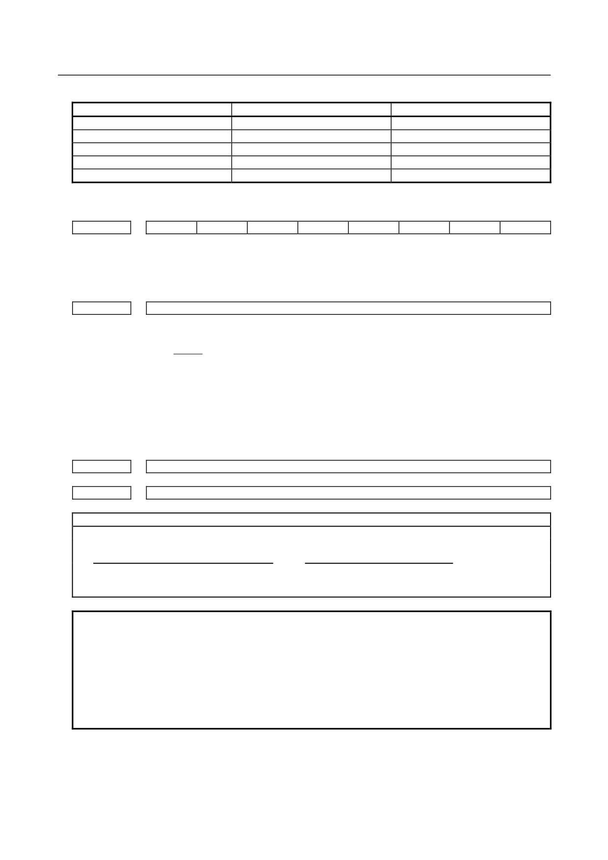
Table 8.1 (h) αCi series servo motor
Motor model
Motor specification
Motor type No.
αC4/3000i
0221
271
αC8/2000i
0226
276
αC12/2000i
0241
291
αC22/2000i
0246
296
αC30/1500i
0251
301
(3)
Arbitrary AMR function
#7
#6
#5
#4
#3
#2
#1
#0
2001
AMR7
AMR6
AMR5
AMR4
AMR3
AMR2
AMR1
AMR0
Set "00000000".
(4)
CMR
1820
Command multiply ratio
1)
When CMR is 1/2 to 1/27
1
Set value=
CMR + 100
2)
When CMR is 1 to 48
Set value=2×CMR
(5)
Turn off the power then back on.
(6)
N/M of flexible feed gear (F⋅FG)
2084
n for flexible feed gear
2085
m for flexible feed gear
Setting for the αi Pulsecoder in the semi-closed mode
Necessary position feedback
F⋅FG numerator (≤ 32767)
pulses per motor revolution
F⋅FG denominator (≤ 32767)
=
1,000,000 (Note 2)
(as irreducible fraction)
(Note 1)
NOTE
1 For both F⋅FG number and denominator, the maximum setting value (after
reduced) is 32767.
2 αi Pulsecoders assume one million pulses per motor revolution, irrespective of
resolution, for the flexible feed gear setting.
3 If the calculation of the number of pulses required per motor revolution involves
p, such as when a rack and pinion are used, assume π to be approximately
355/113.
[Example]
If the machine is set to detection in 1,000 degree units with a gear reduction ratio of 10:1 for
the rotation axis, the table rotates by 360/10 degrees each time the motor makes one turn.
1000 position pulses are necessary for the table to rotate through one degree.
- 311 -
8.DIGITAL SERVO
B-64305EN/03
The number of position pulses necessary for the motor to make one turn is:
360/10 × 1000 = 36000 with reference counter =36000
F⋅FG numerator
36000
36
=
=
F⋅FG denominator
1,000,000
1000
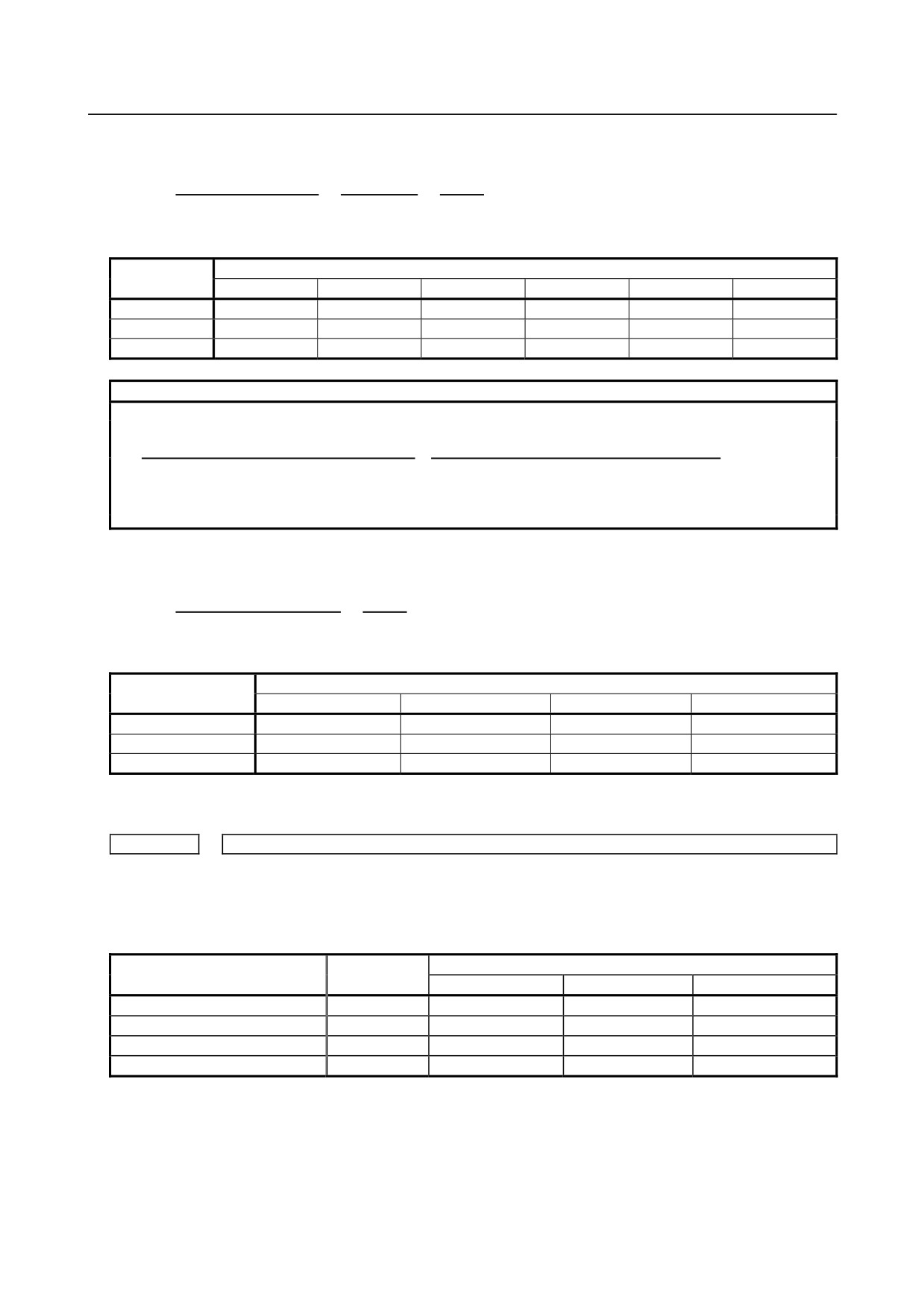
Other F⋅FG (numerator/denominator) setting examples (reduction ratio = 1:1)
Detection
Ball screw lead
unit
6mm
8mm
10mm
12mm
16mm
20mm
1μm
6 /1000
8/1000
10/1000
12/1000
16/1000
20/1000
0.5μm
12 /1000
16/1000
20/1000
24/1000
32/1000
40/1000
0.1μm
60 /1000
80/1000
100/1000
120/1000
160/1000
200/1000
Setting for use of a separate detector (full-closed)
Number of position pulses corresponding to a
F⋅FG numerator (≤ 32767)
predetermined amount of travel
(as irreducible
F⋅FG denominator (≤ 32767)
= Number of position pulses corresponding to a
fraction)
predetermined amount of travel from a
separate detector
[Example]
To detect a distance of 1 μm using a 0.5 μm scale, set the following:
Numerator of F⋅FG
L/1
1
=
=
Denominator of F⋅FG
L/0.5
2
Other F⋅FG (numerator/denominator) setting examples
Resolution of scale
Detection unit
1μm
0.5μm
0.1μm
0.05μm
1μm
1/1
1/2
1/10
1/20
0.5μm
-
1/1
1/5
1/10
0.1μm
-
-
1/1
1/2
(7) Direction of travel
2022
Rotational direction of motor
111 : Normal (clockwise) / -111 : Reverse (counterclockwise)
(8)
Number of speed pulses, Number of position pulses
Semi-closed
Closed loop
loop
Parallel type
Serial linear scale
Serial rotary scale
Command unit (μm)
1/0.1
1/0.1
1/0.1
1/0.1
Initial bit setting
Bit 0=0
Bit 0=0
Bit 0=0
Bit 0=0
Number of speed pulses
8192
8192
8192
8192
Number of position pulses
12500(*1)
(*2 - Example 1)
(*2 - Example 1)
(*2 - Example 2)
Set 8192 as the number of speed pulses.
- 312 -

B-64305EN/03
8.DIGITAL SERVO
NOTE
1
Setting of the number of position pulses for the semi-closed loop (indicated by
(*1) in the above table)
Set 12500.
2
As the number of position pulses, set the number of pulses fed back from a
separate detector when the motor makes one revolution. (The flexible feed gear
has no relevance to the calculation of the number of position pulses.)
Example 1:
When a ball screw (direct connection) with a 10-mm lead and a separate
detector with a resolution of 0.5 μm per pulse are used
When the motor makes one revolution, the following pulses are fed back from
the separate detector:
10/0.0005 = 20,000
Accordingly,
Number of position pulses = 20,000
Example 2:
When a serial rotary scale with a resolution of 1,000,000 pulses per revolution is
used, the number of position feedback pulses is exceptionally calculated by the
following:
12500 × (deceleration ratio between the motor and table)
When the deceleration ratio between the motor and table is 10:1, for example,
the number of position pulses is:
12,500 × (1/10) = 1250
3
When the set number of position pulses is greater than 32767
Using the position feedback pulse conversion coefficient makes setting easier as
described on the following page.
With a position feedback pulse conversion coefficient, the number of position pulses is set using the
product of two parameters.
2024
Number of position pulses
2185
Conversion coefficient for the number of position feedback pulses
(Example of setting)
When a linear scale with a minimum resolution of 0.1 (m is used and the travel distance per motor
revolution is 16 mm:
Ns = (travel distance per motor revolution (mm))/(minimum resolution of detector (mm))
= 16 mm/0.0001 mm = 160000 (>32767) = 10000 × 16
So, set the following:
A: 10000
B: 16
NOTE
If the detector of the motor is an αi Pulsecoder (the number of speed pulses =
8192), select a power of 2 (such as 2, 4, 8, and so on) as a conversion
coefficient whenever possible. (The position gain value used inside the software
becomes more accurate.)
- 313 -