FANUC SERVO AMPLIFIER a series. DESCRIPTIONS (B-65162E/03) - page 20
B-65162E/03
12. DETECTORS FOR THE SPINDLE
(4) Outline Drawing
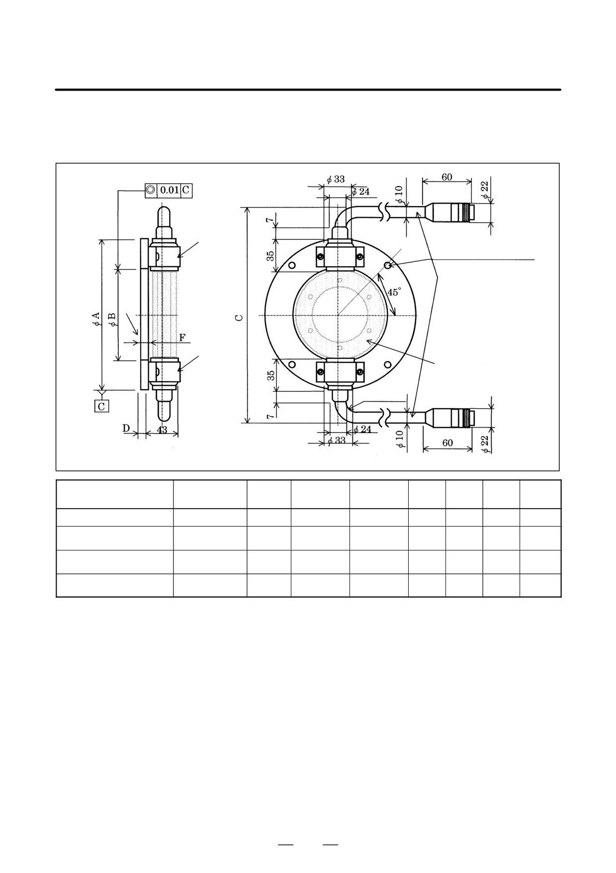
(a) High-resolution magnetic pulse coder (Cs axis sensor)
Sensor
4- φ5.5, equally spaced
on φE circumference
Signal line 400 mm
Reference surface
Sensor
Magnetic drum
R20 or more
Resolu-
Sensor drawing No.
Detection ring
φA
φB
C
D
φE
F
tion
A860-0382-T121
Drum 1
360,000
140–0.015
70–0.011
191
6
130
15"0.2
+0.015
A860-0382-T122
Drum 2
360,000
170–0.015
110
-0.0
224
10
160
19"0.2
+0.015
A860-0382-T123
Drum 3
360,000
200–0.015
140
-0.0
256
10
190
19"0.2
+0.015
A860-0382-T124
Drum 4
360,000
270–0.015
210
-0.0
321
10
260
19"0.2
For the dimensions of the drums, see Item (b).
573
12. DETECTORS FOR THE SPINDLE
B-65162E/03
NOTE
- Use this sensor at temperatures not exceeding 50°C.
- The high-resolution magnetic pulse coder is equipped with a preamplifier.
- A sensor set consisting of a magnetic drum, sensor, and preamplifier is adjusted prior to
shipment, and the same serial number is stamped onto each of the components constituting
that set. When using this sensor, check the serial numbers to ensure that the sensor set does
not include a component having a different serial number. Moreover, never detach the sensor
from its mounting plate.
- This sensor consists of electronic circuits and includes many magnetic components. Never
expose the sensor to a magnetic field of 20 gauss or more. Be careful not to place the sensor
in a magnetic field. Never place a magnet or magnetized object near this sensor.
- Check the output signals of this sensor. For output signal adjustment, refer to Part II of the
”FANUC Built-in AC Spindle Motor α Series Descriptions (B-65202EN).”
574
B-65162E/03
12. DETECTORS FOR THE SPINDLE
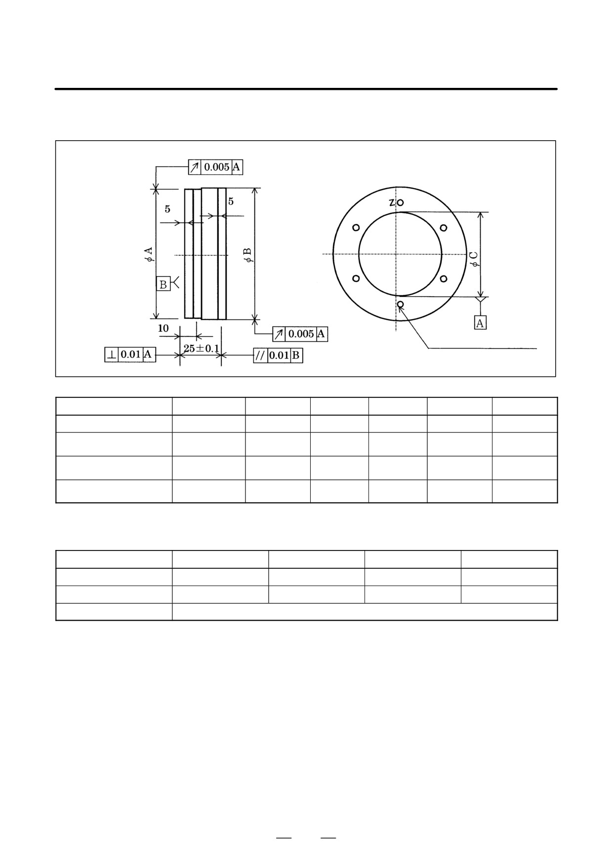
(b) Magnetic drum
6- φD, equally spaced
on φE circumference
Sensor drawing No.
Detection ring
φA
φB
φC
φD
φE
A860-0382-T121
Drum 1
64.05"0.01
65–0.015
50–0.011
---
---
A860-0382-T122
Drum 2
96.55"0.01
97.5–0.015
70–0.015
5.5
80
+0.015
A860-0382-T123
Drum 3
129.05"0.01
130–0.015
105
-0.0
5.5
115
+0.015
A860-0382-T124
Drum 4
194.05"0.01
195–0.015
160
-0.0
6.5
175
For the outside dimensions of the sensor, see Item (a).
Maximum drum speed
Sensor drawing No.
T121
T122
T123
T124
Drum
Drum 1
Drum 2
Drum 3
Drum 4
Maximum speed (min-1)
15,000
13,000
10,000
6,500
Drum material
SUS303
575
12. DETECTORS FOR THE SPINDLE
B-65162E/03
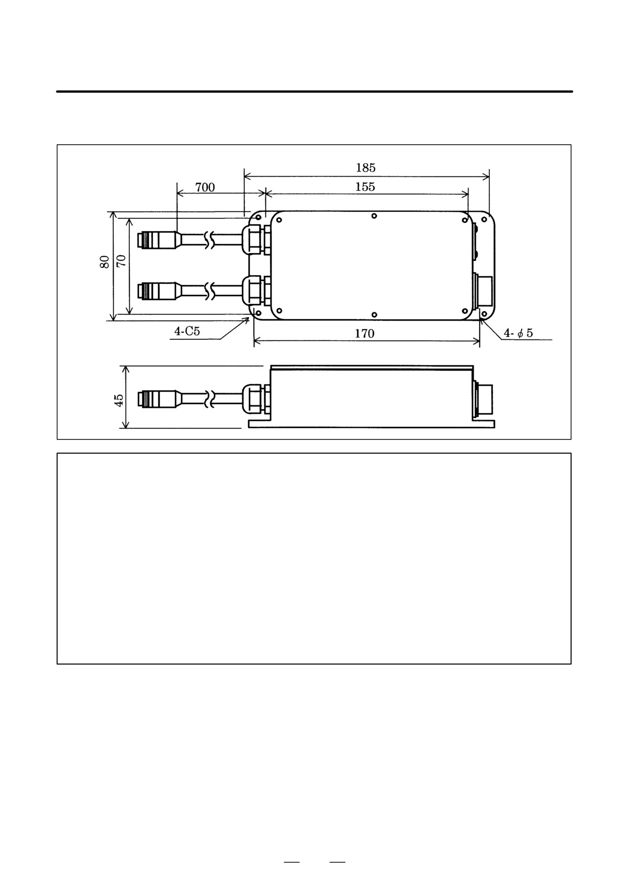
(c) Preamplifier
NOTE
- Use this preamplifier at temperatures not exceeding 50°C.
- This preamplifier is required when the high-resolution magnetic pulse coder is used.
- A sensor set consisting of a magnetic drum, sensor, and preamplifier is adjusted prior to
shipment, and the same serial number is stamped onto each of the components constituting
a set. When using this sensor, check the serial numbers to ensure that the sensor set does
not include a component having a different serial number. Moreover, never detach the sensor
from its mounting plate.
- Ensure that a vibration of no more than 1 G is applied to the preamplifier.
- The waterproofing of the preamplifier case satisfies IP55. However, if this preamplifier is
exposed to coolant, for example, at all times, or is always wet, it may fail. Be careful, therefore,
not to expose the preamplifier to coolant and so forth.
- Check the output signals of this sensor. For output signal adjustment, refer to Part II of the
”FANUC Built-in AC Spindle Motor α Series Descriptions (B-65202EN).”
576
B-65162E/03
12. DETECTORS FOR THE SPINDLE
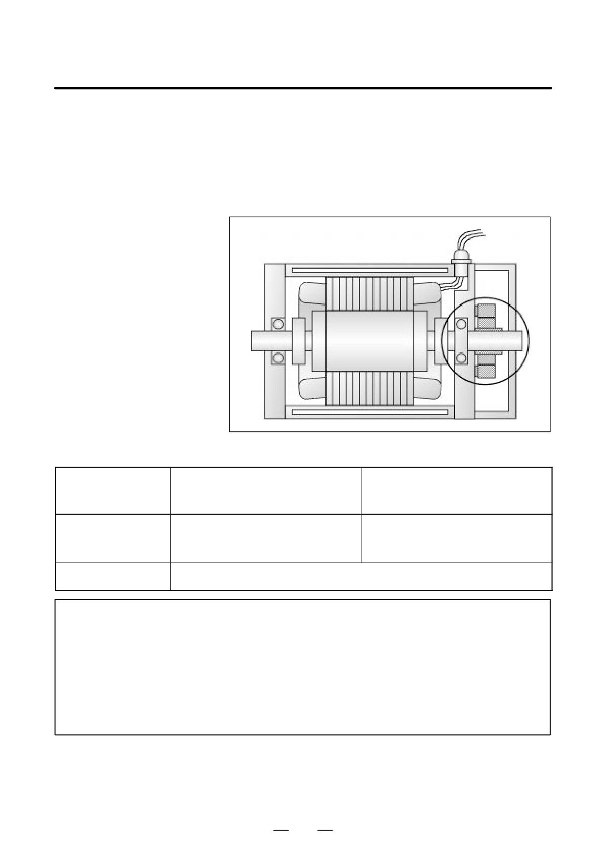
(5) Mounting the High-resolution Magnetic Pulse Coder
The high-resolution magnetic pulse coder is mounted on the rotation axis
of the spindle on the motor power line side. If the high-resolution
magnetic pulse coder is mounted incorrectly, the motor cannot be
controlled correctly. Mount the high-resolution magnetic pulse coder
correctly. In addition, mount a cover or attach a sheet to protect against
the ingress of foreign matter.
1 Mounting a magnetic drum
A860-0382-T122
Sensor
A860-0382-T121
A860-0382-T123
A860-0382-T124
Mount the drum by shrink fitting the drum or ex-
Secure the drum by installing screws in the 6-
pansion fitting the sleeve. For information
Mounting a drum
5.5 holes on the drum. Until centering is com-
about the fitting allowance for each speed, see
pleted, to not tighten the screws fully.
Item (5).5.
Mount the drum so that the reference surface of the drum faces the nose of the spindle. The
Drum mounting direction
reference surface of the drum is on the opposite side to the surface on which Z is printed.
NOTE
- Use a magnetic material for the motor housing to minimize magnetic leakage from the motor.
- Ensure that the motor housing is at least 15 mm thick at the sensor mounting section.
- After assembling the drum with the sleeve, mount the drum onto the spindle. Use a
configuration where the sleeve holds the drum on the motor side (left side in the figure above).
If this configuration is impossible, use a non-magnetic material (such as stainless steel) for the
sleeve.
- If a magnetic substance is placed at the back of the magnetic drum (on the right side in the figure
above), allow a clearance of 30 mm.
577
12. DETECTORS FOR THE SPINDLE
B-65162E/03
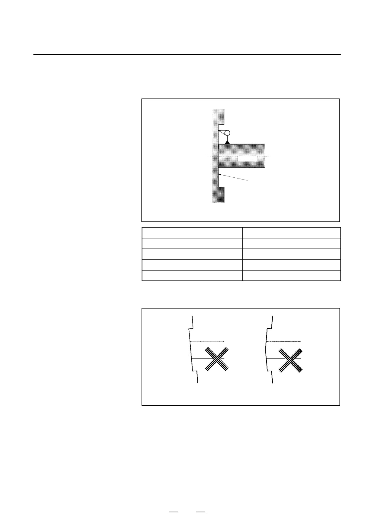
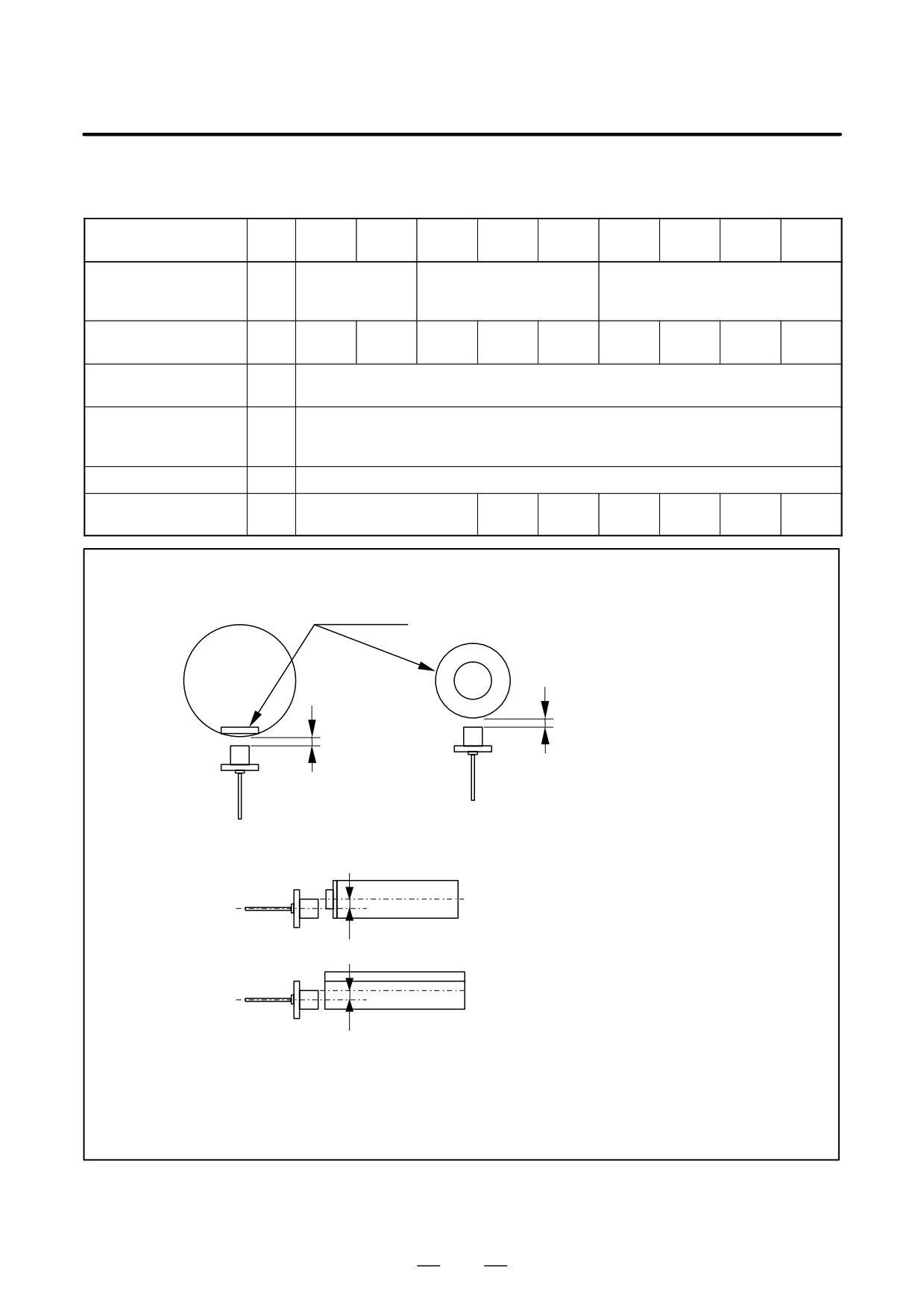
2 Flatness of the sensor mounting plane
The table below indicates the maximum allowable flatness values. Adjust
the flatness to satisfy these requirements.
Dial gauge
Shaft
Reference mounting surface
Sensor drawing No.
Maximum fluctuation (µm)
A860-0382-T121
20
A860-0382-T122
25
A860-0382-T123
30
A860-0382-T124
40
If the reference surface is inclined or is not flat, an abnormal signal may
be detected.
Inclined
Not flat
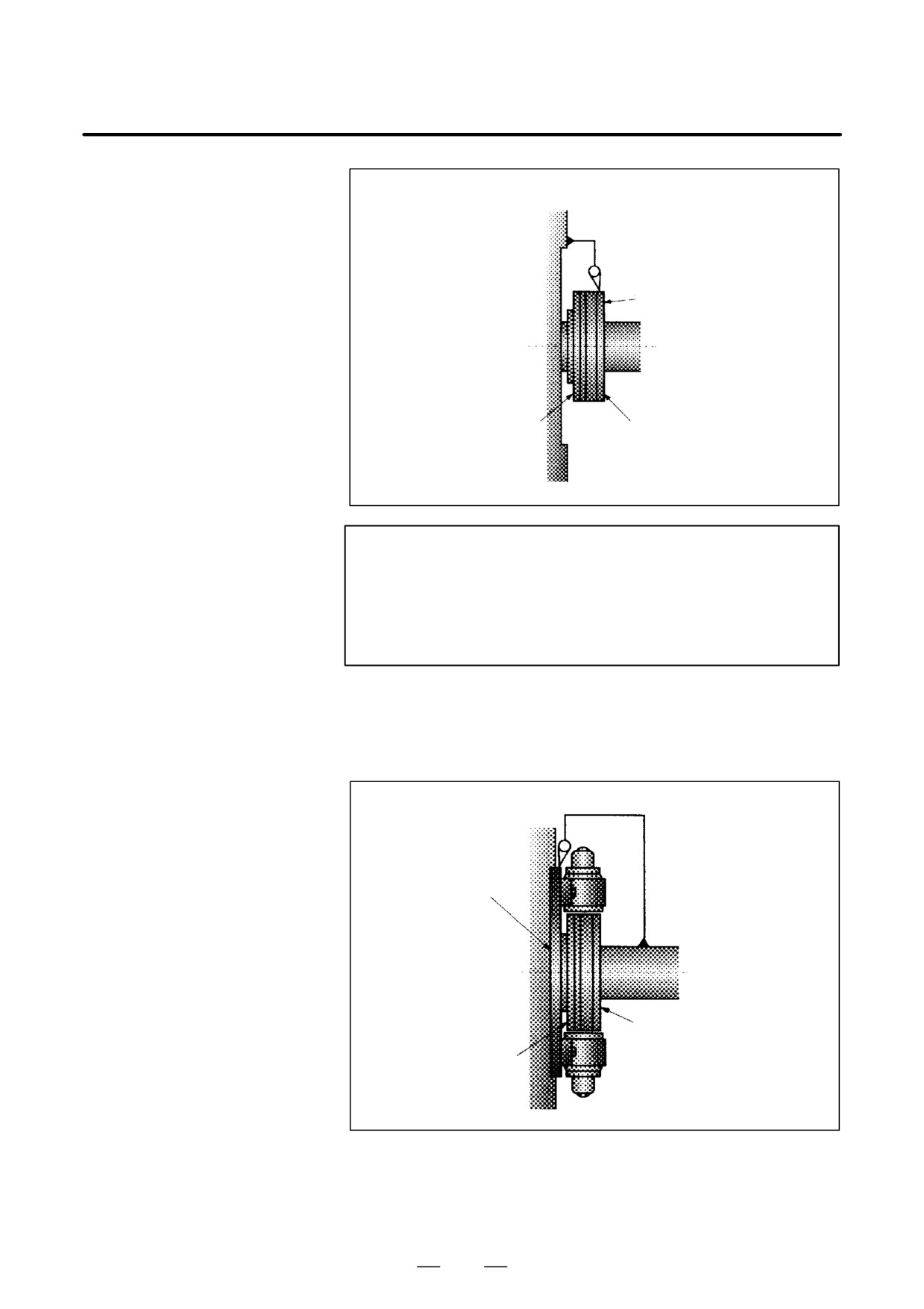
3 Fluctuation of the circumference of the drum
Ensure that the fluctuation of the circumference of the drum is within 15
µ m.
578
B-65162E/03
12. DETECTORS FOR THE SPINDLE
Dial gauge: 15µm or less
Surface on which Z is printed
Shaft
Drum reference surface
Magnetic drum
NOTE
When touching the cylindrical drum surface with a dial
gauge, touch an area within 5 mm of the surface on which
Z is printed. The other area on the drum surface holds
magnetic information, so that information may be lost if the
other area is touched with a dial gauge.
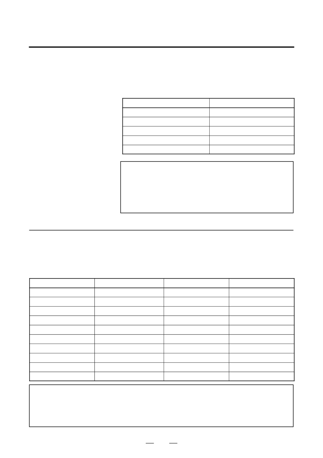
4 Fluctuation of the mounting plate socket and spigot joint
Ensure that the fluctuation of the mounting plate socket and spigot joint
is within 20 µ m with respect to the shaft.
Dial gauge: 20µm or less
Reference mounting
surface
Shaft
Surface on which Z is printed
Magnetic drum
579
12. DETECTORS FOR THE SPINDLE
B-65162E/03
5 Fitting allowance (A860-0382-T121)
The drum for the A860-0382-T121 is mounted by shrink fitting (or
expansion fitting of the shaft). (The other types of drums are mounted by
screwing. See Item (5).1 above.) The table below lists the fitting
allowances.
Maximum speed (min-1)
Allowance (µm)
6000
φ26 to φ47
8000
φ27 to φ48
10000
φ27 to φ48
12000
φ28 to φ49
15000
φ30 to φ51
NOTE
- From the table above, select the allowance that matches the
maximum speed being used. If an incorrect allowance is
employed, idle rotation or deformation can result.
- The drum may be heated up to 100°C. Never heat the drum
to temperatures in excess of 100°C.
12.3.2
Magnetic Sensor (for
Orientation)
(1) Names and Drawing Numbers
Table.12.3.2 (a) Names and Drawing Numbers
Name
Drawing No.
Maximum speed
Shape
Not specified (standard)
A57L-0001-0037
12,000min-1
30
50
Magnetic sensor N, NIP
A57L-0001-0037#N,#NIP
12,000min-1
30
50
Magnetic sensor P, PIP
A57L-0001-0037#P,#PIP
12,000min-1
10
50
Magnetic sensor Q, QIP
A57L-0001-0037#Q,#QIP
20,000min-1
Inner diameter φ40
Magnetic sensor R, RIP
A57L-0001-0037#R,#RIP
20,000min-1
Inner diameter φ50
Magnetic sensor S, SIP
A57L-0001-0037#S,#SIP
15,000min-1
Inner diameter φ60
Magnetic sensor T, TIP
A57L-0001-0037#T,#TIP
15,000min-1
Inner diameter φ70
Magnetic sensor U, UIP
A57L-0001-0037#U,#UIP
20,000min-1
36
50
Magnetic sensor U1, U1IP
A57L-0001-0037#U1,#U1IP
15,000min-1
Inner diameter φ80
Magnetic sensor U2, U2IP
A57L-0001-0037#U2,#U2IP
15,000min-1
Inner diameter φ90
NOTE
With #*IP, the connector is waterproof.
The outer diameter of a cable usable with a waterproof connector is φ8.5 to φ9.7 (including
tolerance).
A waterproof connector, when fitted, satisfies IP64.
580
B-65162E/03
12. DETECTORS FOR THE SPINDLE
(2)
Absolute Maximum Ratings
Table.12.3.2 (b) Absolute Maximum Ratings
Item
Specifications
Power supply voltage
0V to +18V
Operating temperature
0_C to +50_C
Humidity
30% to 90% RH (no condensation)
(3)
Electrical Specifications
Table.12.3.2 (b) Absolute Maximum Ratings
Item
Specifications
Power supply voltage
DC15V"5%
Current consumption
100mA or less
Table.12.3.2 (c) Electrical Specifications
Channel
Signal
CH 1
1/rev (MSA-MSB)
CH 2
1/rev (LSA-LSB)
(4)
Output Pin Configuration
Table.12.3.2 (d) Output Pin Configuration
Pin
A
B
C
D
E
F
Signal name
MSA
0V
+15V
MSB
LSB
LSA
581
12. DETECTORS FOR THE SPINDLE
B-65162E/03
(5) Types of Magnets
Table.12.3.2 (e) Types of Magnets
Sensor
Sensor
Sensor
Sensor
Sensor
Sensor
Sensor
Sensor
Sensor
Item
Unit
N
P
U
Q
R
S
T
U1
U2
Surface speed:
Maximum spindle speed
min-1
3770/m/min or
20,000
15,000
less
33"
14.8"
315"
460"
770"
1000"
1540"
1700"
Magnet weight
g
100"3
1.5
0.7
10
10
15
20
25
30
Gap between magnet
mm
1.0 to 2.0
and sensor (Note 1)
Displacement between
magnet center and sen-
mm
0 to "2.0
sor center (Note 2)
Operating temperature
n
0 to 50
Applicable axis dimen-
mm
---
40–0.025
50–0.025
60–0.025
70–0.025
80–0.025
90–0.025
sions
NOTE
1
Magnet
1 to 2 mm
1 to 2 mm
2
3
If the distance from the center to the location where a magnet is installed is large, the maximum
speed is limited by centrifugal force.
4
The use of high-tensile screws is recommended for magnet installation.
582
B-65162E/03
12. DETECTORS FOR THE SPINDLE
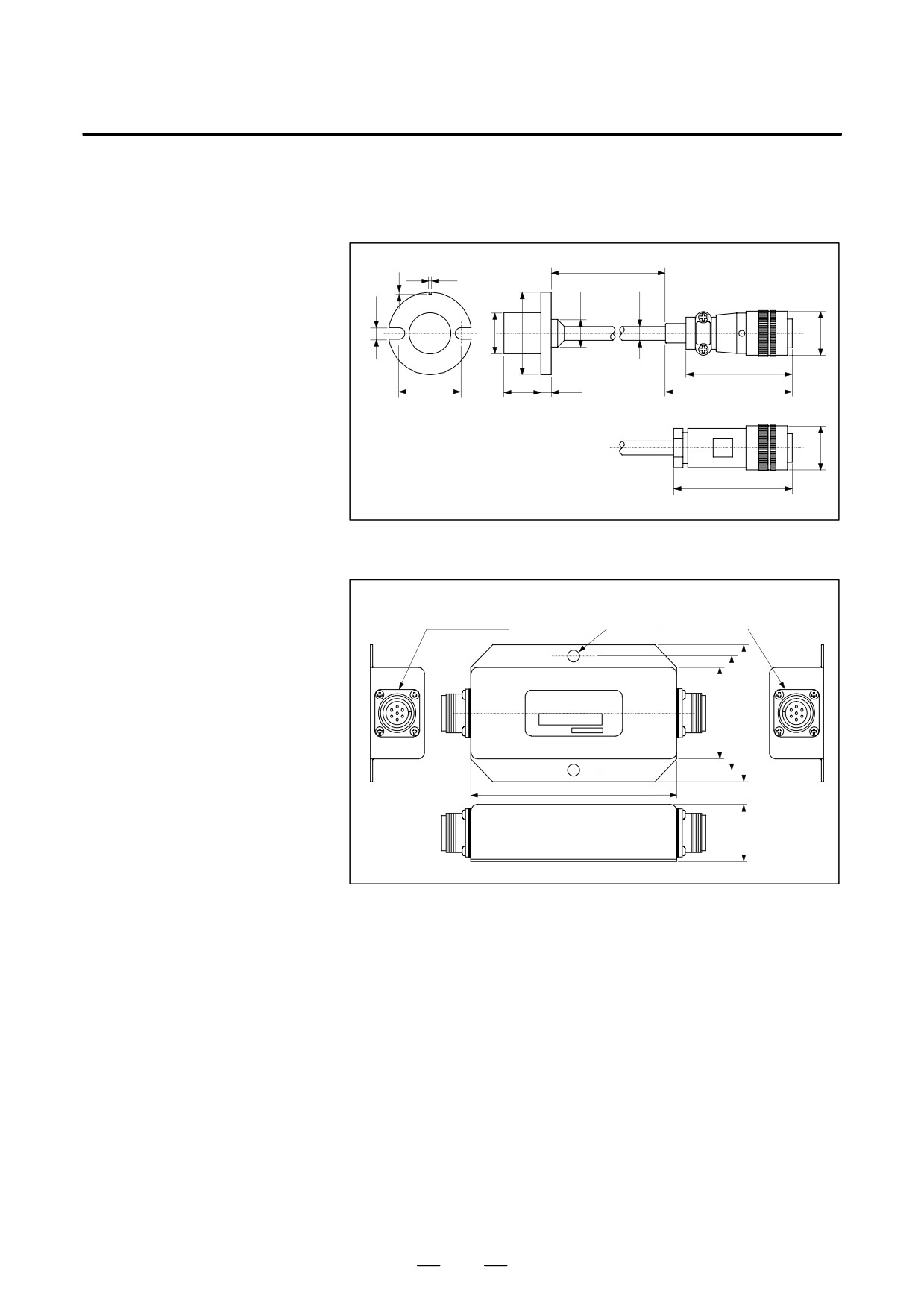
(6) Outline Drawing
1 Detection head
-L-
For standard
1
1
specification
TRC-116-12A-7M
12φ
6φ
5
18φ
36φ
20φ
46
27
16
4.5
55
For IP specification
TRC-116-9008P7M6.3
20φ
52
2 Detector
Detection head
IN receptacle
2-φ
5.4
Output receptacle
TRC-116-21A10-7F
TRC-116-21A10-7M
FANUC
MAGUNETIC SENSOR
A57L-0001-0037
40 50
60
MAKOME CORP.
95
25
583
12. DETECTORS FOR THE SPINDLE
B-65162E/03
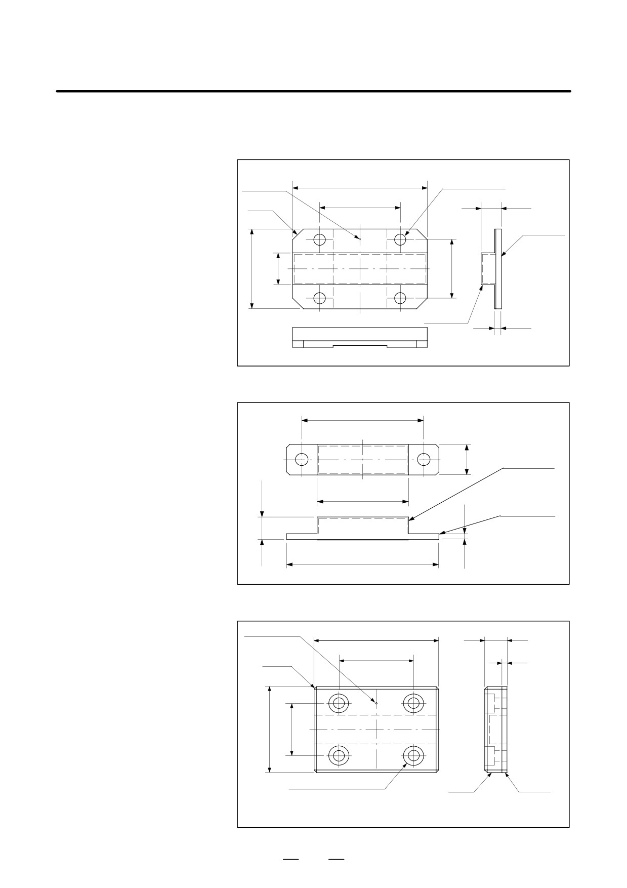
3 Magnet
(1) Magnet for N
Reference
50
Mounting hole
hole
4-φ
4.3
φ
1.0
30
7.5
4-C4
SPC:2.0t
30
12
22
SUS:0.5t
2.5
(2) Magnet for P
40
SUS:0.5t
10
7.5
SPC:2.0t
2
50
(3) Magnet for U
Reference hole
+0
50-0.5
9
φ
1.0
30
2
4-C1
–0.5
+0
36
30
Mounting hole 4-φ4.5
SUS303
SPC:2.0t
φ8 counterboring depth 4
584
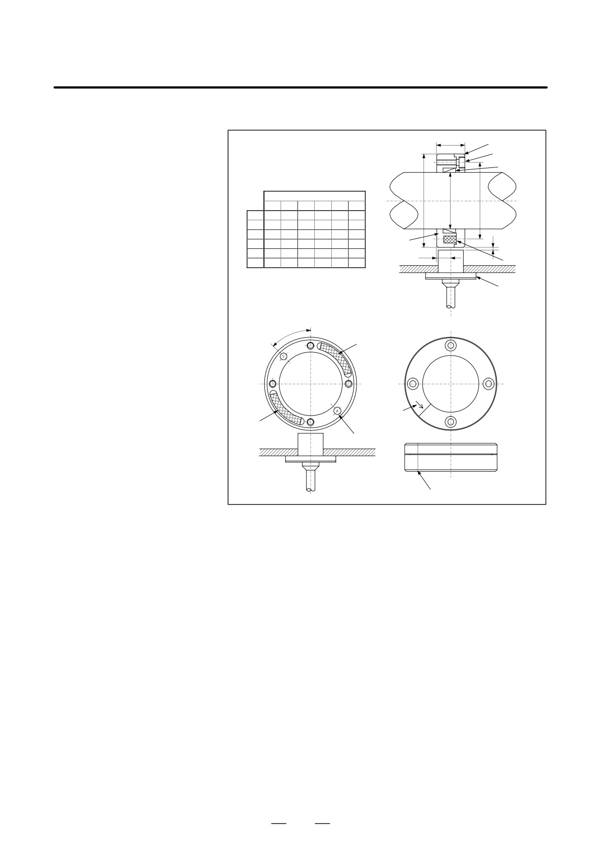
B-65162E/03
12. DETECTORS FOR THE SPINDLE
(4) Magnet for Q, R, S, T, U1, and U2
C
Cover (SUS)
Bolt (4 pcs)
Shupan ring
Spindle
φA
φB
Detailed dimensions
A
B
C
D
E
F
φEH7
(Axis tolerance h6)
Q
66
54
20
9
40
54
R
78
66
23
11
50
66
S
94
79
25
12
60
79
T
105
90
28
14
70
90
Case (SUS)
2
102
34
19
80
102
Distance to the
U1
118
D
center of a
U2
125
112
34
19
90
112
magnet
Magnetic sensor
Without a cover
With a cover
45k
Material for balancing
Arrow (stamped)
Magnet
2- 5φ through hole
Equally spaced on
φF circumference
Magnet reference line
585
12. DETECTORS FOR THE SPINDLE
B-65162E/03
(7) Notes on Use
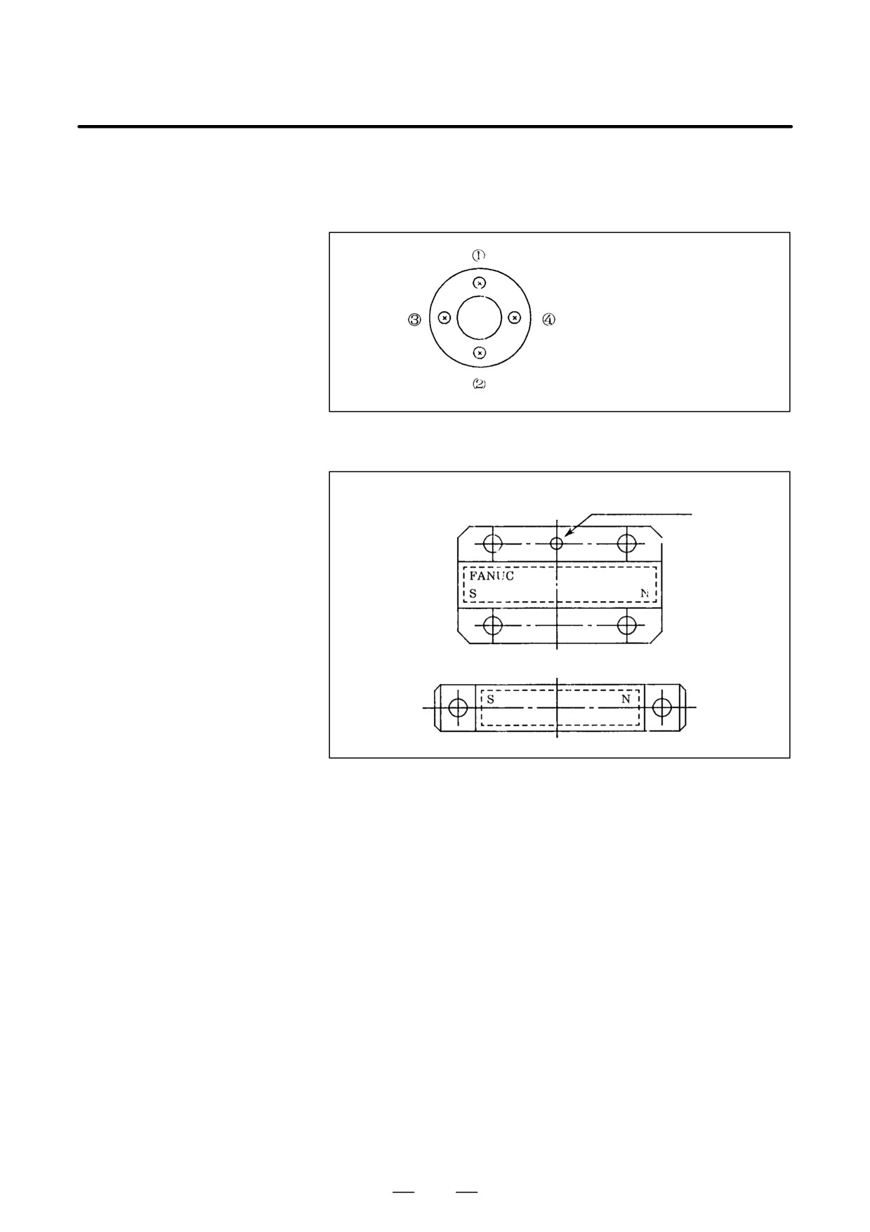
D A Shupan ring (ring-feeder) is used in a magnet. So, tighten the four
bolts evenly.
Tighten the bolts in order from
À to à repeatedly, in stages.
D The reference hole and polarity of a magnet are related to each other
as shown below.
Reference hole φ1.0
D The two holes (φ5.0) on the side opposite the side on which magnetic
sensor Q, R, S, or T is installed with screws should be used for a jig
for orientation position setting.
586
B-65162E/03
12. DETECTORS FOR THE SPINDLE
(8) Mounting a Magnetic Sensor
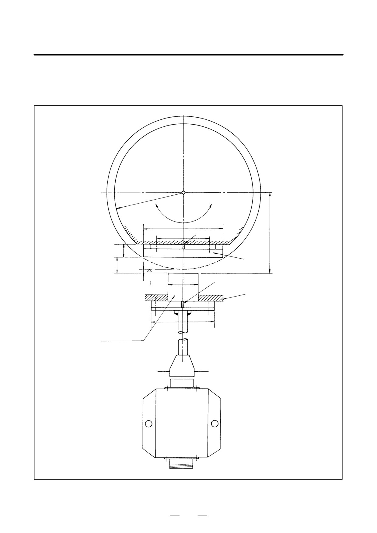
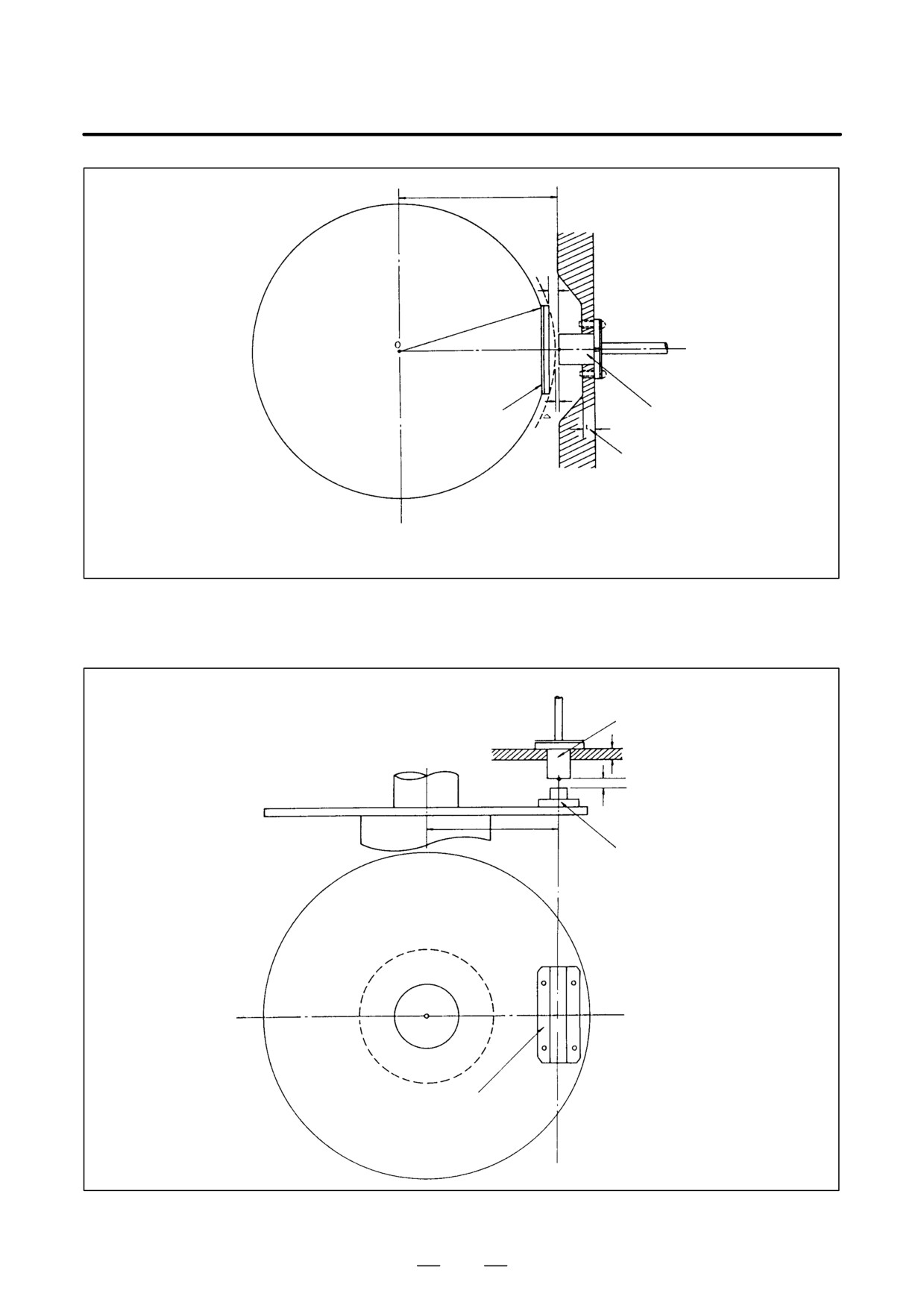
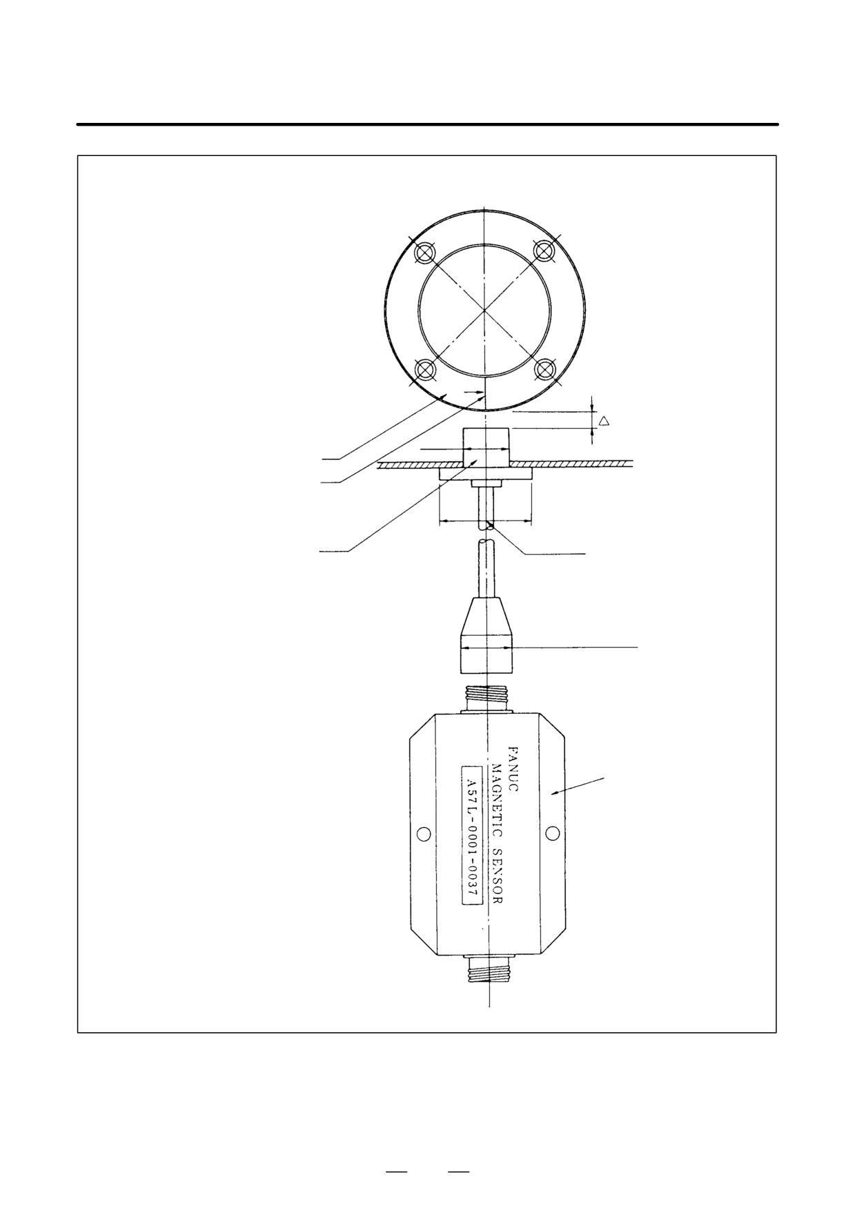
Fig.12.3.2 (a), (b), and (d) show how to mount a magnetic sensor.
Spindle (rotating body)
R
Mounting distance
H [mm]
60 to 110mm
50
30
Reference hole (upper)
7.5
Magnetic
Gap
L=6mm
L
(Standard)
1.0mm
φ18
Pin groove (upper)
2.0mm
Mounting plate
(not thicker than 8mm)
φ36
Magnetic sensor head
Metal socket
φ20.0
Magnetic sensor
amplifier
Fig.12.3.2 (a) Example of Mounting a Magnetic Sensor (1)
587
12. DETECTORS FOR THE SPINDLE
B-65162E/03
Distance H: 60 to 110 mm
Spindle (rotating body)
Magnet
Magnetic sensor head
Mounting plate
(not thicker than 8mm)
ΔL=10 to 20mm
L=8mm or less (Standard: 6mm)
Note) There must be a gap of 8mm
or more between the mounting plate
and magnet.
Fig.12.3.2 (b) Example of Mounting a Magnetic Sensor (2) (Mounting a Magnetic Sensor on a Cylinder)
Magnetic sensor head
Mounting plate
(not thicker than 8mm)
A
L=1 to 2mm
Distance H:
Center
Magnet
60 to 110mm
O
R
A
Inner side
Be careful not to allow iron
chips or powder to adhere
to this area.
Fig.12.3.2 (c) Example of Mounting a Magnetic Sensor (3) (Mounting a Magnetic Sensor on a Disk)
588
B-65162E/03
12. DETECTORS FOR THE SPINDLE
Mounting a magnetic sensor
L=10 to 20mm
Magnet polarity indication
Stop position check scale
Mounting plate
(not thicker than 8mm)
φ36
Magnetic sensor head
Metal socket
φ20
Magnetic sensor amplifier
Fig.12.3.2 (d) Example of Mounting a Magnetic Sensor (4) (Mounting Magnetic Sensor Q, R, S, or T)
589
12. DETECTORS FOR THE SPINDLE
B-65162E/03
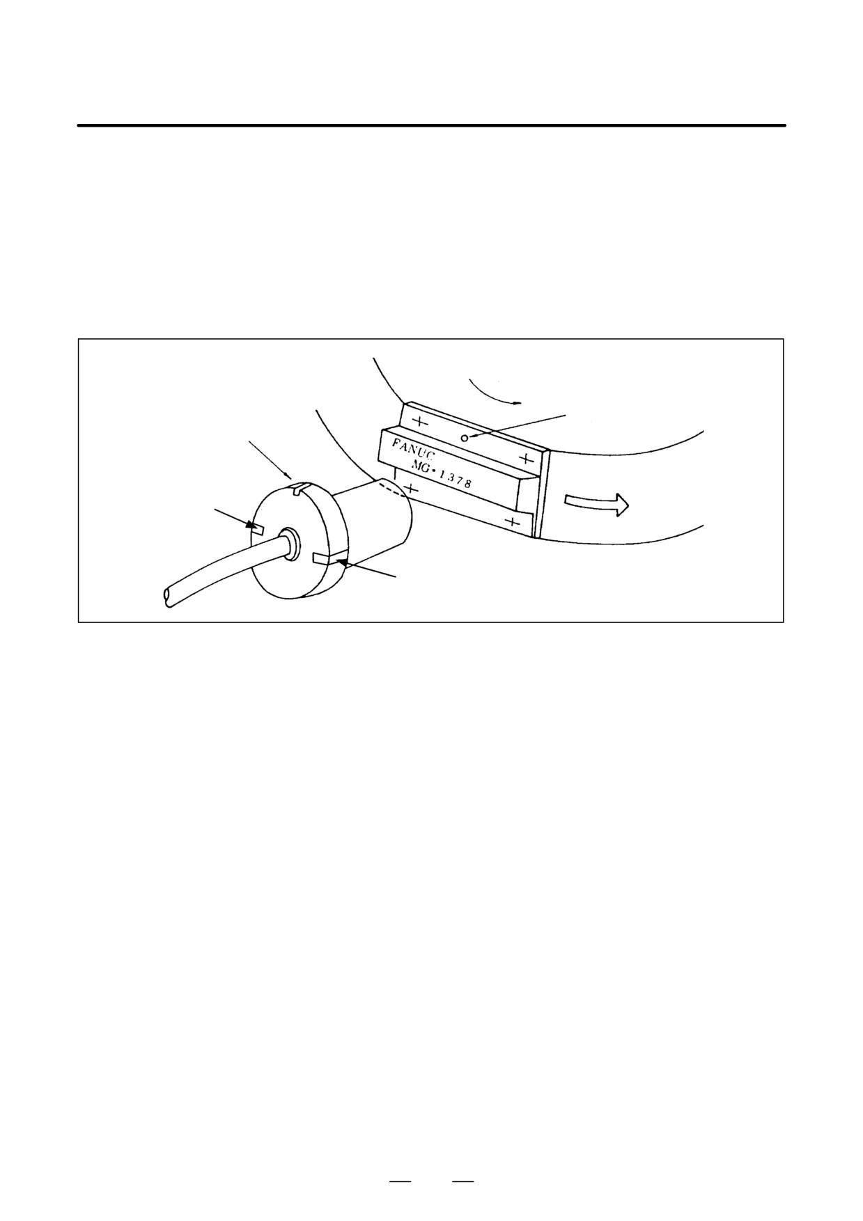
(9) Mounting Method
When a magnet is mounted on the spindle of a machine tool, the mounting
direction depends on the spindle configuration (belt or gear connection)
because of the polarity relationship with a magnetic sensor. When the
connection shown in the magnetic sensor interface is used, the relative
positions of the magnet reference hole and magnetic sensor pin groove
must be as shown below. Otherwise, forward and reverse rotations may
be repeated without stopping.
Magnet reference hole
Magnetic sensor
head pin groove
Rotation direction
Slit for fixing
Slit for fixing
If SFRA (forward rotation command) = 1, all spindle motors rotate
counterclockwise when viewed from the motor shaft. Align the magnet
reference hole with the magnetic sensor pin groove so that the rotation
direction shown above is achieved when the forward rotation command
is on.
590
B-65162E/03
12. DETECTORS FOR THE SPINDLE
(10) Notes on Mounting a Magnetic Sensor
(a)
A magnetic sensor is mounted on the rotation body of the spindle.
So, ensure that a magnet is not dislodged by centrifugal force. The
surface speed of a magnet should not exceed 3770 m/min. (N and P
types)
(b)
Mount a magnetic sensor amplifier as close to the sensor as possible.
(c)
Never allow a magnetic substance to come close to the magnetic
sensor.
(Otherwise, the stop position may change.) In particular,
never place a magnetic device such as a solenoid near the magnet.
(d)
Be careful not to allow iron chips or powder to adhere to the magnet.
(e)
If the spindle contains a circuit such as a magnetic clutch for high/low
switching that forms a magnetic loop, mount a magnet on a
non-magnetic (such as aluminum) plate. The magnetic flux of the
magnet at a stop position is zero. However, if the magnetic loop of
a magnetic clutch has an influence, a magnetic flux is always applied
when the magnetic clutch is on. Note that if the magnetic clutch is
turned on and off at a stop position, the stable magnetic flux changes,
thus causing the stop position to change.
(f)
Pay careful attention to the configuration so that the cable side of the
magnetic sensor head, magnetic sensor amplifier, and connection
cables are not exposed to lubricant or coolant.
(g)
Mount the magnet of a magnetic sensor directly on the spindle. If a
magnet is mounted by means of a gear connection or spline
connection, the repeatability degrades, depending on the amount of
backlash between the spindle and magnet.
For improved
repeatability, also consider deterioration with age
(such as
mechanical wear).
591
12. DETECTORS FOR THE SPINDLE
B-65162E/03
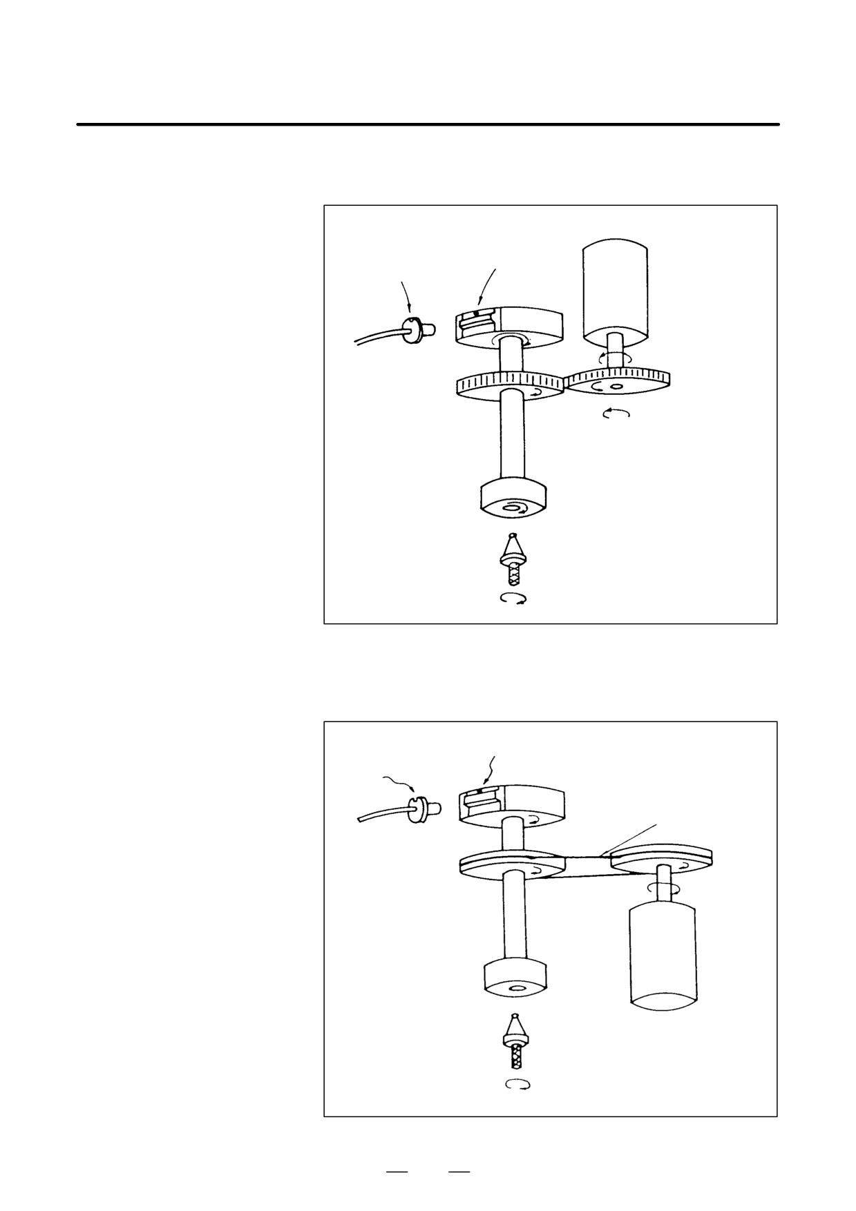
[Mounting example 1]
Forward rotation
Magnetic
signal when SFR
Magnetic sensor
reference hole
contact is ON
pin groove
SPINDLE
(closed)
MOTOR
Gear
connection
CCW
CW
[Mounting example 2]
Magnetic
Magnetic sensor
reference hole
pin groove
Belt connection
SPINDLE
MOTOR
CCW
CW
592
B-65162E/03
12. DETECTORS FOR THE SPINDLE
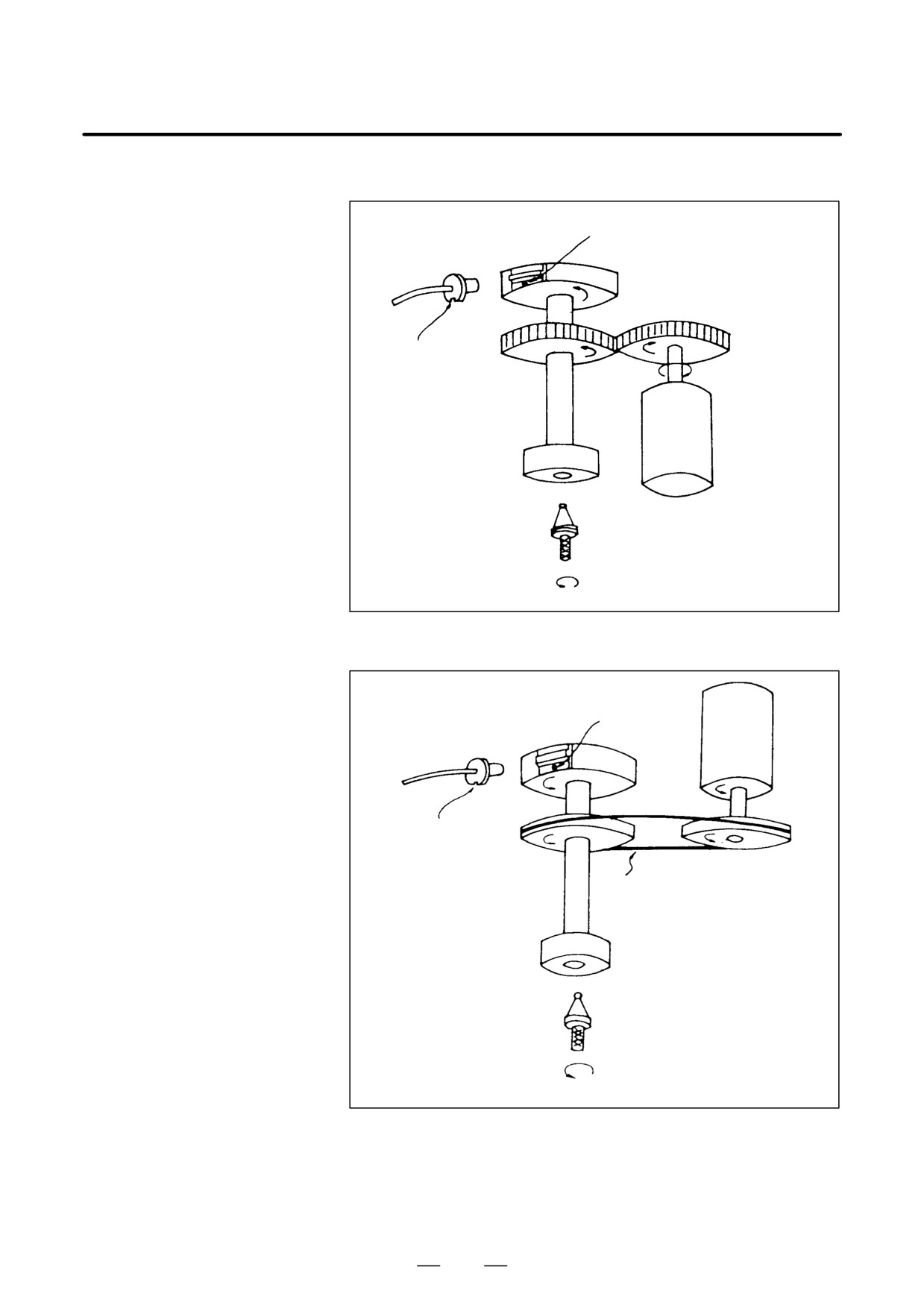
[Mounting example 3]
Magnetic
reference hole
Gear
connection
Magnetic sensor
pin groove
SPINDLE
MOTOR
CCW
CCW
[Mounting example 4]
Magnetic
reference hole
SPINDLE
MOTOR
Magnetic sensor
pin groove
CCW
Belt connection
CCW
593
12. DETECTORS FOR THE SPINDLE
B-65162E/03
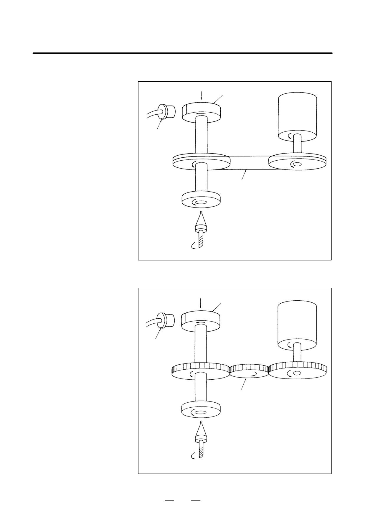
[Mounting example 5]
Screw fastening direction
Polarity indication
Magnet
N S
AC SPINDLE
MOTOR
Magnetic sensor
head pin groove
CCW
Belt connection
CCW
[Mounting example 6]
Screw fastening direction
Polarity indication
Magnet
N S
AC SPINDLE
MOTOR
Magnetic sensor
head pin groove
CCW
Gear connection
CCW
594
APPENDIX
A. FITTING A LIGHTNING SURGE
PROTECTION DEVICE
APPENDIX
B-65162E/03
FITTING A LIGHTNING SURGE PROTECTION DEVICE
A
This appendix describes how to install a lightning surge protector and
provides notes on installation. For information about the lightning surge
protector recommended by FANUC, see Section 8.1.11.
596
A. FITTING A LIGHTNING SURGE
B-65162E/03
APPENDIX
PROTECTION DEVICE
A.1
INSTALLATION
A.1.1
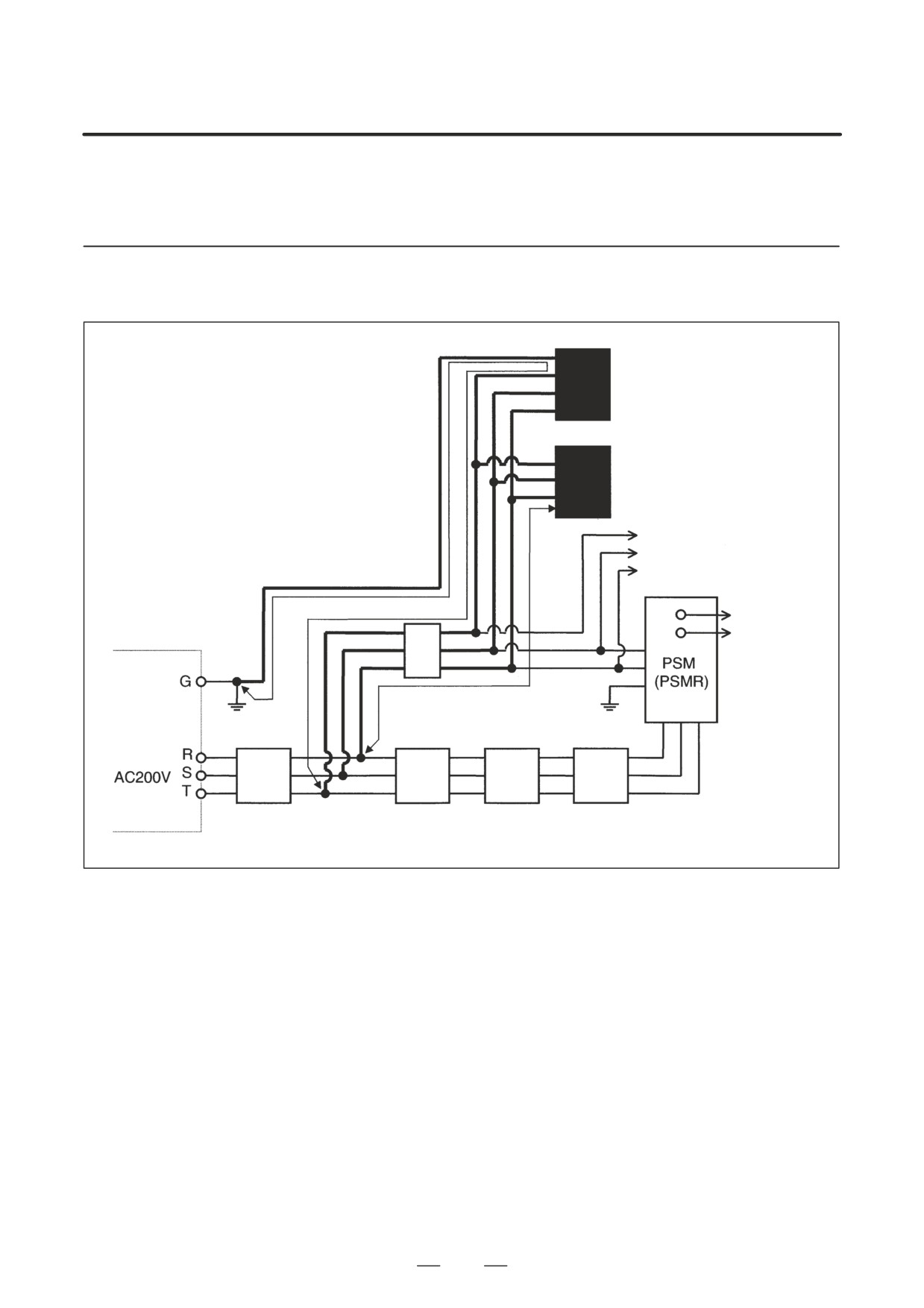
200V Power Supply
Line-to-ground lightning
surge protector
(R A V-781BXZ-4)
Line-to-line lightning
surge protector
(R A V-781BYZ-2)
To other units
(a)
(b)
To SPM/SVM
Control
Circuit breaker 2
power
Grounding plate
(5A)
supply input
Main circuit power
supply input
Ground fault inter-
Circuit breaker 1
Magnetic
AC reactor
rupter for boards
contactor
597
A. FITTING A LIGHTNING SURGE
PROTECTION DEVICE
APPENDIX
B-65162E/03
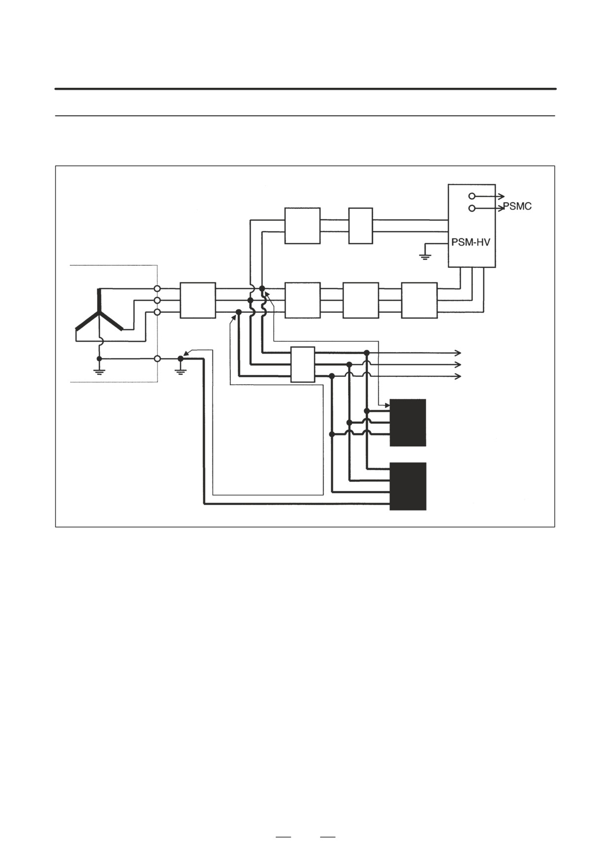
A.1.2
400V Power Supply
Control power
supply input
Voltage-reducing
Circuit breaker 2
transformer
AC400V/460V
→AC200V/s30V
Main circuit
power supply
input
Ground fault
Circuit breaker 1
Magnetic
AC reactor
interrupter for
contactor
boards
To built-in fan motor
of spindle motor
Grounding
Power supply
plate
Circuit breaker 3
(a)
(Y connection neu-
(5A)
tral point grounding)
Line-to-line lightning
AC400V/460V
surge protector
(R A V-152BYZ-2A)
Line-to-ground lightning
surge protector
(b)
(R A V-801BXZ-4)
598
A. FITTING A LIGHTNING SURGE
B-65162E/03
APPENDIX
PROTECTION DEVICE
A.2
D To increase the efficiency of lightning surge absorption, the wires
NOTES
indicated by bold lines should be as short as possible.
Wire cross-sectional area:
2 mm2 or more
Wire length:
The total length of the cables used for lightning surge protection
device 1 (a) and that used for lightning surge protection device 2
(b) must not exceed 2 m.
D When performing a dielectric strength test by applying an overvoltage
to the power line, lightning surge protection device 2 must be removed
to enable the applied voltage to be maintained.
D The circuit protector (5 A) works for line protection when the lightning
surge absorber is short-circuited because of a surge higher than its
rating being applied.
D Because current does not flow through the lightning surge absorber 1
nor 2 in a normal state, the circuit protector (5 A) can be used together
with the surge absorbers as well as with other equipment. It can be
connected to the power supply for power supply module control or
spindle motor fans.
D Use Y connection neutral point grounding for the 400 V power
supply. It cannot be used for the Δ connection 400/460 VAC line.
599
B. SUMMARY OF AMPLIFIER
CONNECTORS
APPENDIX
B-65162E/03
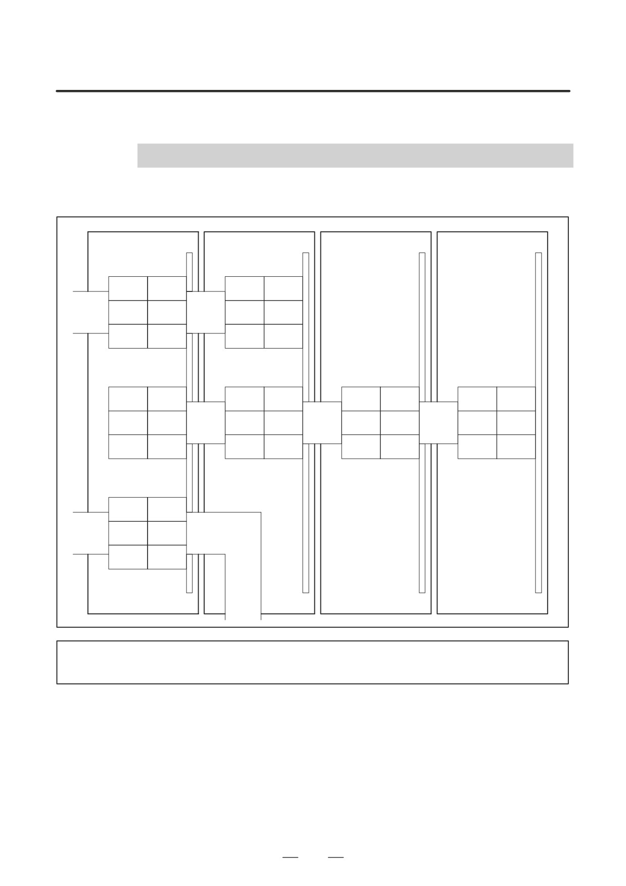
SUMMARY OF AMP CONNECTORS
B
Power supply module
Spindle amplifier module
Servo amplifier module
Servo amplifier module
CX1A
CX1B
CX1A
CX1B
(LEFT)
(RIGHT)
(LEFT)
(RIGHT)
(3)
(3)
(3)
(3)
PE
(2)
(2)
(2)
(2)
Cable
Cable
200S
200S
200S
200S
K3
K4
(1)
(1)
(1)
(1)
200R
200R
200R
200R
350/X
350/X
350/X
350/X
CX2A
CX2B
CX2A
CX2B
CX2A
CX2B
CX2A
CX2B
(LEFT)
(RIGHT)
(LEFT)
(RIGHT)
(LEFT)
(RIGHT)
(LEFT)
(RIGHT)
(3)
(3)
(3)
(3)
(3)
(3)
(3)
(3)
ESP
ESP
ESP
ESP
ESP
ESP
ESP
ESP
(2)
(2)
(2)
(2)
(2)
(2)
(2)
(2)
Cable
Cable
Cable
0V
0V
K5
0V
0V
K5
0V
0V
K5
0V
0V
(1)
(1)
(1)
(1)
(1)
(1)
(1)
(1)
+24V
+24V
+24V
+24V
+24V
+24V
+24V
+24V
250/X
250/X
250/X
250/X
250/X
250/X
250/X
250/X
CX3
CX4
(LEFT)
(RIGHT)
(3)
(3)
MCCOFF3
+24V
Cable
(2)
(2)
Cable
K6
ESP
K7
(1)
(1)
MCCOFF4
350/Y
350/X
PCB
PCB
PCB
PCB
NOTE
Details such as connector locations may be changed without notice.
600
B-65162E/03
APPENDIX
C. CABLES
CABLES
C
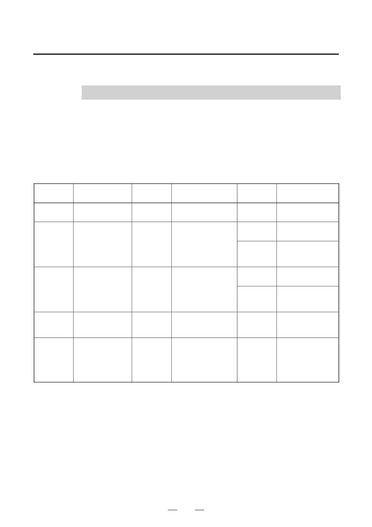
This appendix describes the cables used for the
20-pin interface
connectors.
The cables are basically the same as those used for the FS16/18 (except
those that have been newly developed).
The table below lists the cables we have developed for interface
connectors. Contact the manufacturers as required.
Configura-
Manufactur-
Manufacturer
Cable name
Purpose
FANUC specification
tion
er
specification
2
For motor thermostat
0.3mm
Hitachi
CO-IREV (0)-SX
2-core cable
A66L-0001-0275
of αC series
2 wires
Cable, Ltd
1P
0.3SQ
Hitachi
UL20276-SB(0)
Cable, Ltd.
10PX28AWG(7/0.127)
0.09 mm2
10-pair cable
For general use
A66L-0001-0284#10P
10 pairs
Oki Electric
Cable Co.,
7/0.127 10P VX10-SV
Ltd.
Hitachi
F-CO-VV(0)-SB
0.5 mm
2
Cable, Ltd.
6X0.5SQ+3PX0.18SQ
Composite
For pulse coder
6 cables
12-core
For magnetic sensor
A66L-0001-0286
0.18 mm
2
Oki Electric
cable
For position coder
MIX12C(7/0.18,
3 pairs
Cable Co.,
20/0.18)HRS-SV
Ltd.
2
Shinko Elec-
For high-resolution
0.18 mm
10-pair cable
A66L-0001-0367
tric Industries
FNC-019
magnetic pulse coder
10 pairs
Co., Ltd.
For pulse generator,
MZ sensor,
0.5 mm
2
Composite
Shinko Elec-
BZ sensor
6 cables
16-core
A66L-0001-0368
tric Industries
FNC-021
2
For built-in sensor
0.18 mm
cable
Co., Ltd.
For high-resolution
5 pairs
position coder
601
C. CABLES
APPENDIX
B-65162E/03
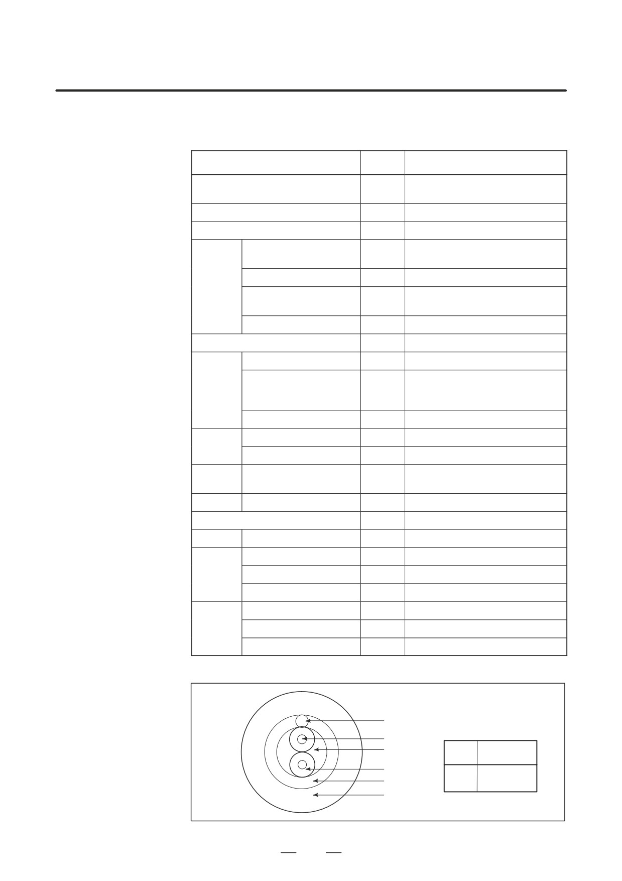
2-core cable
D Specifications
Item
Unit
Specifications
Product No.
-
A66L-0001-0275
(CO-IREV
(0)
–SX 1P
0.3SQ
Manufacturer
-
Hitachi Electric Cable Co., Ltd.
Rating
-
80_C, 30V
Material
Conductor
-
Stranded wire of tinned annealed
copper
Insulator
-
Irradiation Crosslinking Poliethylene
Shield braid
-
Aluminum laminate poliestel tape is
binded on both sides
Sheath
-
Oilproof, heat-resistant vinyl
Number of wires (wire ons.)
Cores
2
Conduc-
Size
mm2
0.3
tor
Structure
Conduc-
7/0.26
tors
/mm
Outside diameter
mm
0.78
Insulator
Standard thickness
mm
0.3
Outside diameter
mm
About 1.38
Twisted
Outside diameter
mm
About 2.8
pair
Strand
Outside diameter
mm
-
Lay diameter
mm
About 3.5
Shield
Element wire diameter
mm
-
Sheath
Color
-
Black
Thickness
mm
About 1.0
Outside diameter
mm
About 5.0 (Max. 5.5)
Electrical
Resistance of conductor
Ω/km
Less than 54 (20°C)
perfor-
Dielectric strength (AC)
V/min.
AC1500
mance
Insulation resistance
MΩ-km
More than 1000 (20°C)
D Specifications
Drain wire
1
Conductor
Lay
Wire No.
color
2
Insulation
1
Red
Shield
2
Black
Sheath
602