FANUC Series 30i-MODEL B, 31i-MODEL B, 32i-MODEL B. MAINTENANCE MANUAL - page 19
9.AC SPINDLE
B-64485EN/01
-
Load meter
The load meter displays spindle load in a unit of 10%.
Load meter data
Load meter [%] =
× Max. output value of load meter (*)
32767
(*) Parameter No. 4127: High-speed winding of main spindle
Parameter No. 4274: High-speed winding of subspindle
Parameter No. 4093: Low-speed winding of main spindle
Parameter No. 4279: Low-speed winding of subspindle
-
Control input signal
Max.10 signals those are ON are displayed from the following signals:
TLML
Torque limit command (low)
SPSL
Spindle selection signal
TLMH
Torque limit command (high)
MCFN
Power line switching
CTH1
Gear signal 1
SOCN
Soft start/stop
CTH2
Gear signal 2
RSL
Output switching request
SRV
Spindle reverse rotation
RCH
Power line state confirm
SFR
Spindle forward rotation
INDX
Orientation stop pos. change
ORCM
Spindle orientation
ROTA
Rotation direction of ORCM
MRDY
Machine ready
NRRO
Short-cut of ORCM
ARST
Alarm reset signal
INTG
Speed integral control signal
*ESP
Emergency stop
DEFM Differential mode command
-
Control output signals
Max. 10 signals those are ON are displayed from the following signals:
ALM
Alarm signal
TLM5
Torque limitation
SST
Speed zero signal
ORAR
Orientation end signal
SDT
Speed detecting signal
CHP
Power line switched signal
SAR
Speed arrival signal
CFIN
Spindle switch complete
LDT1
Load detecting signal 1
RCHP
Output switch signal
LDT2
Load detecting signal 2
RCFN Output switch complete signal
9.1.2.5 Correspondence between operation mode and parameters on
spindle tuning screen
-
Normal operation mode
S11:
S12:
S21:
S22:
1st Main
1st Sub
2nd Main
2nd Sub
Proportional gain (HIGH)
4040
4206
4040
4206
Proportional gain (LOW)
4041
4207
4041
4207
Integral gain (HIGH)
4048
4048
4212
4212
Integral gain (LOW)
4049
4049
Motor voltage
4083
4236
4083
4236
Regenerative power
4080
4231
4080
4231
-
Orientation mode
S11:
S12:
S21:
S22:
1st Main
1st Sub
2nd Main
2nd Sub
Proportional gain (HIGH)
4042
4208
4042
4208
Proportional gain (LOW)
4043
4209
4043
4209
Integral gain (HIGH)
4050
4050
4213
4213
Integral gain (LOW)
4051
4051
Loop gain (HIGH)
4060
4060
4218
4218
Loop gain (MED.HIGH)
4061
4061
- 522 -
B-64485EN/01
9.AC SPINDLE
S11:
S12:
S21:
S22:
1st Main
1st Sub
2nd Main
2nd Sub
Loop gain (MED.LOW)
4062
4062
4219
4219
Loop gain (LOW)
4063
4063
Motor voltage
4084
4237
4084
4237
Gain change upon completion of orientation
4064
4220
4064
4220
Stop position shift
4077
4228
4077
4228
PC-type orientation stop position
4031
4204
4031
4204
-
Synchronization control mode
S11:
S12:
S21:
S22:
1st Main
1st Sub
2nd Main
2nd Sub
Proportional gain (HIGH)
4044
4210
4044
4210
Proportional gain (LOW)
4045
4211
4045
4211
Integral gain (HIGH)
4052
4052
4214
4214
Integral gain (LOW)
4053
4053
Loop gain (HIGH)
4065
4065
4221
4221
Loop gain (MED.HIGH)
4066
4066
Loop gain (MED.LOW)
4067
4067
4222
4222
Loop gain (LOW)
4068
4068
Motor voltage
4085
4238
4085
4238
Acc./Dec. time constant
4032
4032
Shift amount
4034
4034
-
Rigid tapping mode
S11:
S12:
S21:
S22:
1st Main
1st Sub
2nd Main
2nd Sub
Proportional gain (HIGH)
4044
4210
4044
4210
Proportional gain (LOW)
4045
4211
4045
4211
Integral gain (HIGH)
4052
4052
4214
4214
Integral gain (LOW)
4053
4053
Loop gain (HIGH)
4065
4065
4221
4221
Loop gain (MED.HIGH)
4066
4066
Loop gain (MED.LOW)
4067
4067
4222
4222
Loop gain (LOW)
4068
4068
Motor voltage
4085
4238
4085
4238
ZRN gain %
4091
4239
4091
4239
Grid shift amount at servo mode
4073
4223
4073
4223
-
Cs contour control mode
S11:
S12:
S21:
S22:
1st Main
1st Sub
2nd Main
2nd Sub
Proportional gain (HIGH)
4046
4046
Proportional gain (LOW)
4047
4047
Integral gain (HIGH)
4054
4054
Integral gain (LOW)
4055
4055
Loop gain (HIGH)
4069
4069
Loop gain (MED.HIGH)
4070
4070
Loop gain (MED.LOW)
4071
4071
Loop gain (LOW)
4072
4072
Motor voltage
4086
4086
ZRN gain %
4092
4092
Reference position shift
4135
4135
- 523 -
9.AC SPINDLE
B-64485EN/01
-
Spindle positioning control mode
S11:
S12:
S21:
S22:
1st Main
1st Sub
2nd Main
2nd Sub
Proportional gain (HIGH)
4044
4210
4044
4210
Proportional gain (LOW)
4045
4211
4045
4211
Integral gain (HIGH)
4052
4052
4214
4214
Integral gain (LOW)
4053
4053
Loop gain (HIGH)
4065
4065
4221
4221
Loop gain (MED.HIG)
4066
4066
Loop gain (MED.LOW)
4067
4067
4222
4222
Loop gain (LOW)
4068
4068
Motor voltage
4085
4238
4085
4238
ZRN gain %
4091
4239
4091
4239
Reference position shift
4073
4223
4073
4223
9.1.3
Automatic Setting of Standard Parameters
The standard parameters related to each motor model can be set automatically.
* The specifications for controlling a motor depend on the specifications defined by the machine tool
builder. The parameters defined by the machine tool builder are set as the standard values (initial
values) by this automatic setting function. Therefore, when performing automatic operation, always
set parameters properly according to the parameter list (parameters 4000 and later).
1
Turn on the power in the emergency stop state.
2
Set bit 7 of parameter 4019 to 1.
#7
#6
#5
#4
#3
#2
#1
#0
4019
LDSP
[Input type] Parameter input
[Data type] Bit spindle
#7 LDSP The parameters for the serial interface spindle are:
0: Not set automatically.
1: Set automatically.
3
Set a motor model code.
4133
Motor model code
Code
Motor model
Amplifier
301
αiI 0.5/10000 (3000/10000min-1)
αiSP2.2
302
αiI 1/10000 (3000/10000min-1)
αiSP2.2
304
αiI 1.5/10000 (1500/10000min-1)
αiSP5.5
305
αiI 1.5/15000 (3000/150000min-1)
αiSP15
306
αiI 2/10000 (1500/10000min-1)
αiSP5.5
307
αiI 2/15000 (3000/15000min-1)
αiSP22
308
αiI 3/10000 (1500/10000min-1)
αiSP5.5
309
αiI 3/12000 (1500/12000min-1)
αiSP11
310
αiI 6/10000 (1500/10000min-1)
αiSP11
311
αiI 0.5/10000HV (3000/10000min-1)
αiSP5.5HV
312
αiI 8/8000 (1500/8000min-1)
αiSP11
313
αiI 1/10000HV (3000/10000min-1)
αiSP5.5HV
314
αiI 12/7000 (1500/7000min-1)
αiSP15
- 524 -
B-64485EN/01
9.AC SPINDLE
Code
Motor model
Amplifier
315
αiI 1.5/10000HV (1500/10000min-1)
αiSP5.5HV
316
αiI 15/7000 (1500/7000min-1)
αiSP22
317
αiI 2/10000HV (1500/10000min-1)
αiSP5.5HV
318
αiI 18/7000 (1500/7000min-1)
αiSP22
319
αiI 3/10000HV (1500/10000min-1)
αiSP5.5HV
320
αiI 22/7000 (1500/7000min-1)
αiSP26
321
αiI 6/10000HV (1500/10000min-1)
αiSP11HV
322
αiI 30/6000 (1150/6000min-1)
αiSP45
323
αiI 40/6000 (1500/6000min-1)
αiSP45
324
αiI 50/4500 (1150/4500min-1)
αiSP55
325
αiI 8/8000HV (1500/8000min-1)
αiSP11HV
326
αiI 12/7000HV (1500/7000min-1)
αiSP15HV
327
αiI 15/7000HV (1500/7000min-1)
αiSP30HV
328
αiI 22/7000HV (1500/7000min-1)
αiSP30HV
329
αiI 30/6000HV (1150/6000min-1)
αiSP45HV
401
αiI 6/12000 (1500/12000, 4000/12000min-1)
αiSP11
402
αiI 8/10000 (1500/10000, 4000/10000min-1)
αiSP11
403
αiI 12/10000 (1500/10000, 4000/10000min-1)
αiSP15
404
αiI 15/10000 (1500/10000, 4000/10000min-1)
αiSP22
405
αiI 18/10000 (1500/10000, 4000/10000min-1)
αiSP22
406
αiI 22/10000 (1500/10000, 4000/10000min-1)
αiSP26
407
αiIP 12/6000 (500/1500, 750/6000min-1)
αiSP11
408
αiIP 15/6000 (500/1500, 750/6000min-1)
αiSP15
409
αiIP 18/6000 (500/1500, 750/6000min-1)
αiSP15
410
αiIP 22/6000 (500/1500, 750/6000min-1)
αiSP22
411
αiIP 30/6000 (400/1500, 575/6000min-1)
αiSP22
412
αiIP 40/6000 (400/1500, 575/6000min-1)
αiSP26
413
αiIP 50/6000 (575/1500, 1200/6000min-1)
αiSP26
414
αiIP 60/4500 (400/1500, 750/4500min-1)
αiSP30
415
αiI 100/4000HV (1000/3000, 2000/4000min-1)
αiSP75HV
418
αiIP 40/6000HV (400/1500, 575/6000min-1)
αiSP30HV
4
Turn off the power then back on. Then, the parameters are read.
9.1.4
Warning Interface
Overview
The warning state can be reported before an alarm is issued. When the warning state is entered, a report to
the PMC is sent.
For example, this signal can be used for retracting tools or reducing cutting load from the time a warning
occurs by the time an overheat alarm occurs. In addition, the warning number is displayed also on the
diagnosis screen.
Signal
Spindle warning detailed signals SPWRN1 to SPWRN9 <F264.0 to .7, F265.0>
[Classification] Output
[Function] Reports the warning number corresponding to the state of the αi spindle amplifier.
[Output condition] When the αi spindle is in the warning state, a warning number consisting of SPWRN1 to
SPWRN9 is output as nine-bit binary data.
- 525 -
9.AC SPINDLE
B-64485EN/01
If warnings occurred on multiple αi spindle amplifiers, the warning number of the αi
spindle having the smallest axis number is output.
The warning numbers and their descriptions are shown below.
Warning
Contents
Details
number
01
MOTOR OVERHEAT
When the motor temperature increases beyond the overheat warning
detection level (set by a parameter), a warning signal is output. At this
time, spindle operation is continued. So, perform necessary processing
with the PMC.
An alarm is issued when the motor temperature has reached the
overheat alarm detection level.
04
PS IMPROPER INPUT
If an abnormal condition is detected on the main power supply, a
POWER
warning signal is output. Since the spindle continues to operate at this
time, use the PMC to perform processing as needed.
56
COOLING FAN FAILURE
If the internal fan stops, the warning signal is output. Since the spindle
continues to operate at this time, use the PMC to perform processing
as needed.
About one minute after the warning signal is output, an alarm occurs.
58
PS OVERLOAD
If the main circuit of the Power Supply (PS) is overloaded, the warning
signal is output. Since the spindle continues to operate at this time,
use the PMC to perform processing as needed.
An alarm is issued when a certain period of time elapses after warning
signal output.
59
PS INTERNAL FAN
If the Power Supply (PS) cooling fan stops, the warning signal is
FAILURE
output. Since the spindle continues to operate at this time, use the
PMC to perform processing as needed.
About one minute after the warning signal is output, an alarm occurs.
88
COOLING RADI FAN
If the radiator cooling fan stops, the warning signal is output. Since the
FAILURE
spindle continues to operate at this time, use the PMC to perform
processing as needed.
If the main circuit overheats, an alarm occurs.
113
PS EXTERNAL FAN
If the Power Supply (PS) radiator cooling fan stops, the warning signal
FAILURE
is output. Since the spindle continues to operate at this time, use the
PMC to perform processing as needed.
If the Power Supply (PS) main circuit overheats, an alarm occurs.
Signal address
#7
#6
#5
#4
#3
#2
#1
#0
F264
SPWRN8
SPWRN7
SPWRN6
SPWRN5
SPWRN4
SPWRN3
SPWRN2
SPWRN1
F265
SPWRN9
Diagnosis screen
The status of a warning is displayed on the following diagnostic screen.
712
Warning status of spindle
[Data type] Word spindle
The number of a warning caused on each spindle is indicated.
If there is no warning, 0 is indicated.
- 526 -
B-64485EN/01
9.AC SPINDLE
9.1.5
Spindle Information Screen
Overview
In the αi spindle system, ID information output from each of the connected units is obtained and output to
the CNC screen.
The units that have ID information are shown below.
• Spindle amplifier (SP)
• Power Supply (PS)
The ID information recorded during first startup can be compared with the ID information read this time
on the screen to check whether the configuration of the connected units is changed. (If there is a
difference between them, the alarm mark (*) appears.)
The recorded ID information can be edited. Therefore, the ID information of an unit that does not have ID
information can be displayed. (However, the alarm mark (*) indicating a difference between these IDs
appears.)
Parameter
#7
#6
#5
#4
#3
#2
#1
#0
11320
IDC
[Input type] Parameter input
[Data type] Bit path
#1 IDC The soft key [UPDATEALL ID], which updates ID information on the servo or spindle
information screen as a batch, is:
0: Not displayed.
1: Displayed.
NOTE
IDC is effective only if bit 0 (IDW) of parameter No. 13112 is set to
1.
#7
#6
#5
#4
#3
#2
#1
#0
13112
SPI
IDW
[Input type] Parameter input
[Data type] Bit path
#0 IDW Editing on the servo or spindle information screen is:
0: Prohibited.
1: Not prohibited.
#2 SPI The servo information screen is:
0: Displayed.
1: Not displayed.
- 527 -
9.AC SPINDLE
B-64485EN/01
Displaying the spindle information screen
1
Press the
function key, then press the [SYSTEM] soft key.
2
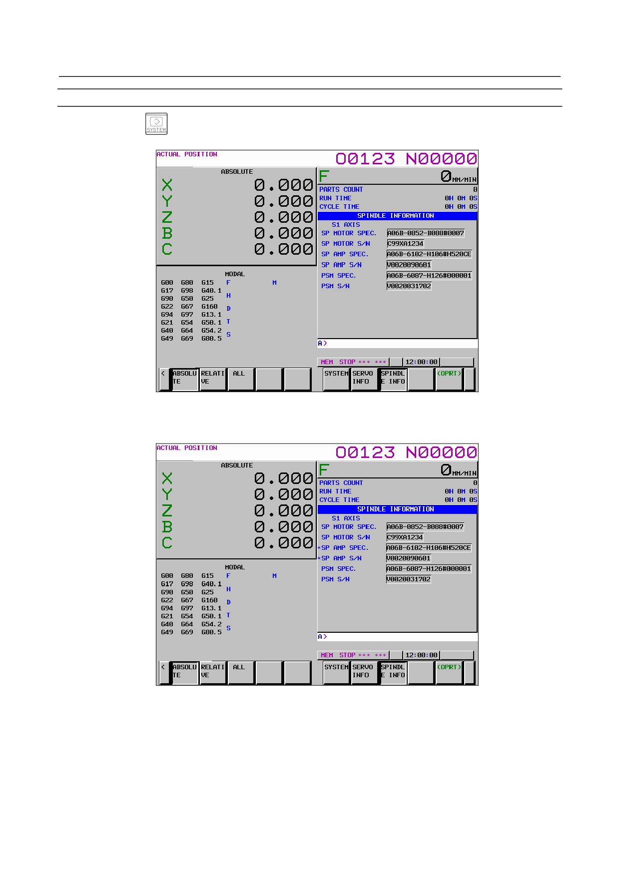
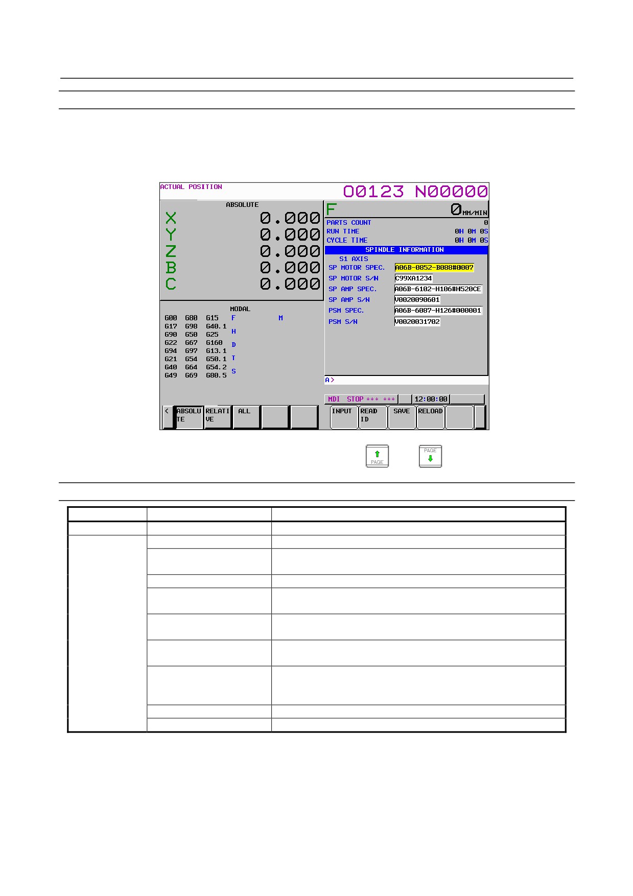
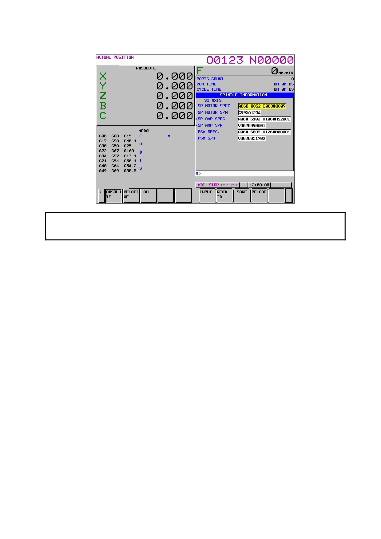
Press the [SPINDLE INFO] soft key to display the screen as shown below.
* Spindle information is stored in flash ROM. If there is a difference between the ID information
in screen and the actual ID information, the corresponding items are preceded by *, as shown
below.
- 528 -
B-64485EN/01
9.AC SPINDLE
-
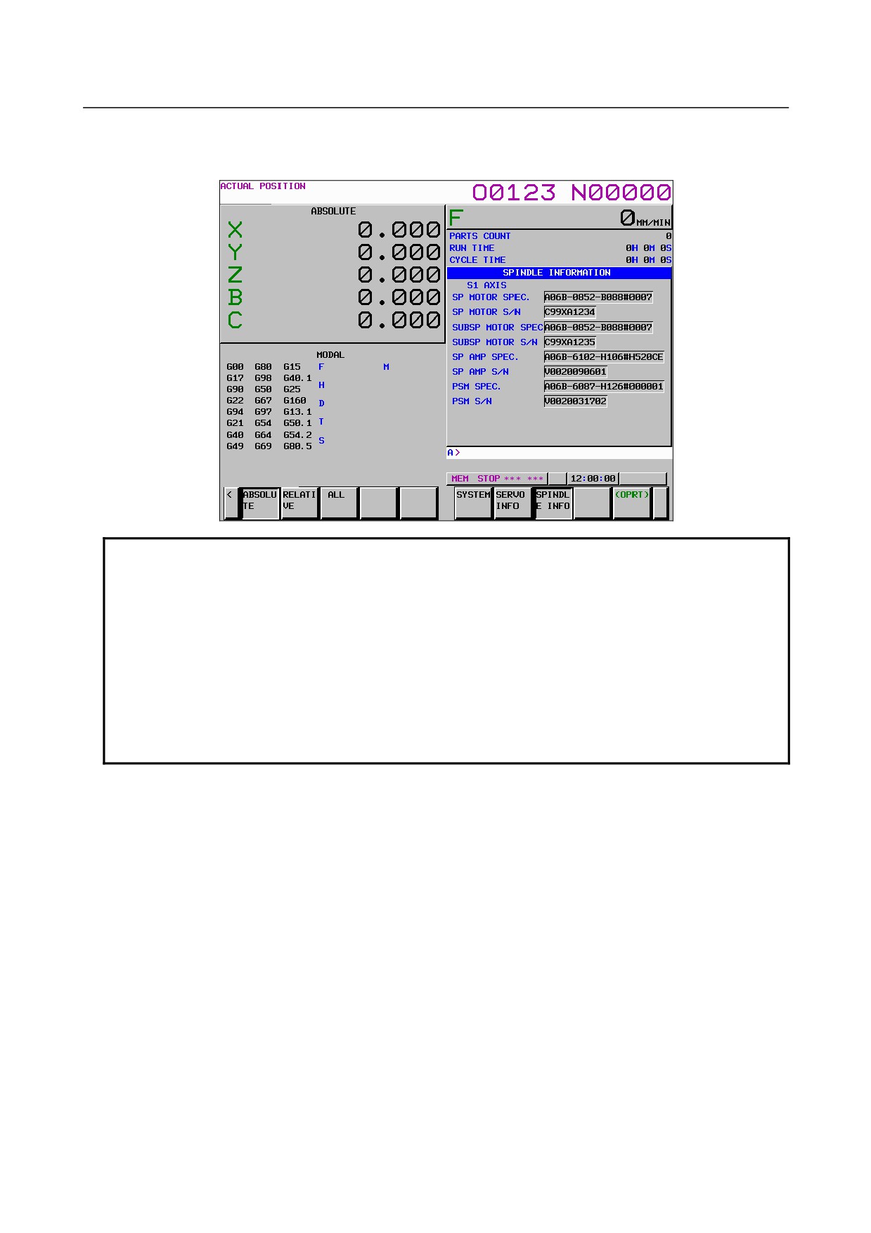
Spindle switch control
When spindle switch control is used, the ID information of the subspindle is also displayed.
Additional Information
Even if replacement is performed reasonably such as for repairing, this function
incorrectly indicates the * mark when it detects the replacement.
To clear the * mark, follow the steps below to update the registered data, as
described in the editing section later.
(1) Make the registered data editable. (Bit 0 (IDW) of parameter No. 13112 = 1)
(2) On the edit screen, place the cursor on the item from which you want to
delete the * mark.
(3) Operate the soft keys [READ ID], [INPUT], and [SAVE] in that order.
To clear all * marks at a time, press soft key [UPDATEALL ID] (displayed when
bit 1 (IDC) of parameter No. 11320 is set to 1).
- 529 -
9.AC SPINDLE
B-64485EN/01
Editing the spindle information screen
1
Assume that bit 0 (IDW) of parameter No. 13112 = 1 and bit 1 (IDC) of parameter No. 11320 = 1.
2
Press the MDI switch on the machine operator's panel.
3
Follow the steps shown in "Displaying the spindle information screen" to display the screen as
shown below.
4
To move key-in buffer on the screen, use the page keys
and
Screen operation on the editing screen
Mode
Key operation
Use
Viewing (*1)
Page key
Scrolls up or down on a screen-by-screen basis.
Editing (*2)
Soft key
[INPUT]
Replace the selected ID information at the cursor position with the
character string in key-in buffer.
[CANCEL]
Deletes the character string in key-in buffer.
[READ ID]
Transfers the ID information the connected device at the cursor has
to the key-in buffer. Only the items preceded by * (*3) are valid.
[SAVE]
Saves the ID information that has been changed on the spindle
information screen in flash ROM.
[RELOAD]
Cancels the ID information that has been changed on the spindle
information screen and loads ID information from flash ROM.
[UPDATEALL ID] (*4)
Updates the ID information for all axes that is output from each of
the connected units displayed on the servo or spindle information
screen at a time.
Page key
Scrolls up or down on a screen-by-screen basis.
Cursor key
Scrolls up or down the selection of ID information.
*1 Viewing mode: when bit 0 (IDW) of parameter No. 13112 = 0
*2 Editing mode: when bit 0 (IDW) of parameter No. 13112 = 1
*3 Spindle information is stored in flash ROM. If there is a difference between the ID information in
screen and the actual ID information, the corresponding items are preceded by *.
*4 when bit 1 (IDC) of parameter No. 11320 = 1
- 530 -
B-64485EN/01
9.AC SPINDLE
NOTE
The ID information of the spindle motor is not displayed automatically. To display
the ID information, enter it manually in the edit mode.
- 531 -

10.TROUBLESHOOTING
B-64485EN/01
10 TROUBLESHOOTING
This chapter describes troubleshooting procedure.
10.1 CORRECTIVE ACTION FOR FAILURES
532
10.2 NO MANUAL OPERATION NOR AUTOMATIC OPERATION CAN BE EXECUTED
534
10.3 JOG OPERATION CANNOT BE DONE
537
10.4 HANDLE OPERATION CANNOT BE DONE
540
10.5 AUTOMATIC OPERATION CANNOT BE DONE
544
10.6 CYCLE START LED SIGNAL HAS TURNED OFF
549
10.7 NOTHING IS DISPLAYED ON THE LCD WHEN THE POWER IS TURNED ON
550
10.8 INPUT FROM AND OUTPUT TO I/O DEVICES CANNOT BE PERFORMED
INPUT/OUTPUT CANNOT BE PERFORMED PROPERLY
551
10.9 IN A CONNECTOR PANEL I/O UNIT, DATA IS INPUT TO AN UNEXPECTED ADDRESS553
10.10 IN A CONNECTOR PANEL I/O UNIT, NO DATA IS OUTPUT TO AN EXPANSION UNIT 554
10.11 ALARM SR0085 TO SR0087 (READER/PUNCHER INTERFACE ALARM)
555
10.12 ALARM PS0090 (REFERENCE POSITION RETURN IS ABNORMAL)
559
10.13 ALARM DS0300 (REQUEST FOR REFERENCE POSITION RETURN)
560
10.14 ALARM SV0401 (V READY OFF)
561
10.15 ALARM SV0404 (V READY ON)
563
10.16 ALARM SV0462 (SEND CNC DATA FAILED)
ALARM SV0463 (SEND SLAVE DATA FAILED)
563
10.17 ALARM SV0417 (DIGITAL SERVO SYSTEM IS ABNORMAL)
564
10.18 ALARM OH0700 (OVERHEAT: CONTROL UNIT)
564
10.19 ALARM OH0701 (OVERHEAT: FAN MOTOR)
565
10.20 ALARM SV5134 (FSSB: OPEN READY TIME OUT)
ALARM SV5137 (FSSB: CONFIGURATION ERROR)
ALARM SV5197 (FSSB: OPEN TIME OUT)
565
10.21 ALARM SV5136 (FSSB: NUMBER OF AMPS IS SMALL)
566
10.22 SERVO ALARMS
566
10.23 SPINDLE ALARMS
566
10.24 SYSTEM ALARMS
566
10.25 SYSTEM ALARMS RELATED TO THE PMC AND I/O Link
575
10.26 LEDS ON UNITS SUPPORTING I/O LINK i
584
10.1 CORRECTIVE ACTION FOR FAILURES
When a failure occurs, it is important to correctly grasp what kind of failure occurred and take appropriate
action, to promptly recover the machine.
Check for the failure according to the following procedure :
When?
With what operation?
What failure?
Grasp the kind of failure
↓
Appropriate action
↓
Recovery
- 532 -
B-64485EN/01
10.TROUBLESHOOTING
10.1.1 Investigating the Conditions under which Failure Occurred
(1) When and how many times (frequency of occurrences)
(2) With what operation
(3) What failure occurred
If the alarm issued is a system alarm, obtain system alarm information while referencing the descriptions in Section
10.24.
1
When did the failure occur?
•
Date and time?
•
Occurred during operation? (how long was the operation?)
•
Occurred when the power was turned on?
•
Was there any lightening surge, power failure, or other disturbances to the power supply?
How many times has it occurred
•
Only once?
•
Occurred many times ? (How many times per hour, per day, or per month?)
2
With what operation did it occur ?
•
What was the NC mode when the failure occurred?
Jog mode/memory operation mode /MDI mode /reference position return mode
•
If during program operation,
-
Where in the program ?
-
Which program No. and sequence No. ?
-
What program ?
-
Occurred during axial movement ?
-
Occurred during the execution of an M/S/T code ?
-
Failure specific to the program ?
•
Does the same operation cause the same failure ?
(Check the repeatability of the failure.)
•
Occurred during data input/output ?
<Feed axes and spindles>
•
For a failure related to feed axis servo
(1) Occurred at both low feedrate and high feedrate ?
(2) Occurred only for a certain axis ?
•
For a failure related to spindles
When did the failure occur ? (during power-on, acceleration, deceleration, or constant rotation)
3
What failure occurred ?
•
Which alarm was displayed on the alarm display screen?
(Check the axis along which an alarm has occurred for alarms SV alarms, OT alarms, or SP
alarms.)
•
Is the screen correct ?
•
If machining dimensions are incorrect
(1) How large is the error ?
(2) Is the position display on the CRT correct ?
(3) Are the offsets correct ?
4
Other information
•
Is there noise origin around machine?
If the failure has not occurred frequently, the cause may be external noise to the power supply
or inductive noise on machinery cables.
Operate other machines connected to the same power line and see if noise come from the relays
or compressors.
- 533 -
10.TROUBLESHOOTING
B-64485EN/01
•
Is it taken any countermeasure for noise in machine side?
See Section 2.8, “CAUTIONS RELATED TO GROUNDING AND NOISE”.
•
Check the following for the input power supply voltage :
(1) Is there variation in the voltage ?
(2) Are the voltages different depending on the phase ?
(3) Is the standard voltage supplied ?
•
How high is the ambient temperature of the control unit?
Refer to manual about noise.
•
Has excessive vibration been applied to the control unit?
5
When you contact our service center, specify the following items :
(1) Name of the NC unit
(2) Name of the machine tool builder and type of machine
(3) Software series/version of the NC
(4) Specifications of the servo amplifier and motor
(for a failure related to the servo)
(5) Specifications of the spindle amplifier and spindle motor
(for a failure related to a spindle)
• See the drawing issued by the machine tool builder for the locations of the NC unit and
servo/spindle amplifiers.
• We use the following specification codes :
Servo /spindle amplifier : A06B-xxxx-Hxxx
Servo/spindle amplifier
: A06B-xxxx-Bxxx
NOTE
The mark ‘x’ represents a number.
10.2 NO MANUAL OPERATION NOR AUTOMATIC OPERATION
CAN BE EXECUTED
Points
(1) Execute the following procedure when no manual nor automatic operation is done
(2) Check whether position display shows correct position
(3) Check CNC status display
(4) Check CNC internal status using diagnosis function
Causes and Countermeasures
1
Position display (relative, absolute, machine coordinate) does not change
(1) Check CNC status display (Refer to Section, “CNC STATUS DISPLAY” for detail.)
(a) Emergency stop status (Emergency stop signal is turned on)
If status display shows EMG the emergency stop signal is input. Check the following signal
using the PMC's diagnosis function (PMCDGN).
#7
#6
#5
#4
#3
#2
#1
#0
X0008
*ESP
G0008
*ESP
*ESP :
ESP=0 indicates that emergency stop signal is input.
- 534 -
B-64485EN/01
10.TROUBLESHOOTING
(b) It is a reset status
When RESET is displayed, any of a reset is functioned. Check the following signal using the
PMC's diagnosis function (PMCDGN).
(i)
An input signal from the PMC functions
#7
#6
#5
#4
#3
#2
#1
#0
G0008
ERS
RRW
ERS : When ERS is 1, external reset signal is input.
RRW : When RRW is 1, reset & rewind signal is input.
(ii) RESET key on the MDI unit functions
When the signals in 1) are 0, <RESET> key may be functioning. Check the contact of
<RESET> key using a tester.
When it is abnormal, change the MDI unit.
(c)
Confirm the status of modes
Operation mode status is displayed on the lower part of screen as follows :
If nothing is displayed, mode select signal is not input. Check mode select signal using PMC's
diagnosis function (PMCDGN).
For details, refer to section, “CNC STATUS DISPLAY”.
(Example of display)
JOG
: Manual operation (JOG) mode
HND : Manual handle (MPG) mode
MDI
: Manual data input (MDI) mode
MEM : Automatic operation (Memory) mode
EDIT : EDIT (Memory edit) mode
<Mode select signal>
#7
#6
#5
#4
#3
#2
#1
#0
G0043
MD4
MD2
MD1
↓
↓
↓
Manual operation (JOG) mode
1
0
1
Manual handle (MPG) mode
1
0
0
Manual data input (MDI) mode
0
0
0
Automatic operation (Memory) mode
0
0
1
EDIT (Memory edit) mode
0
1
1
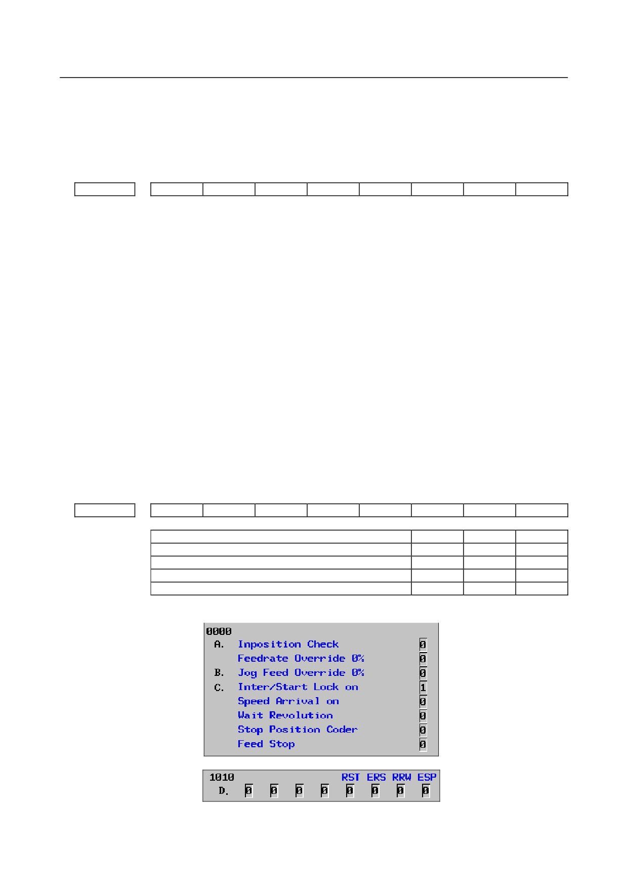
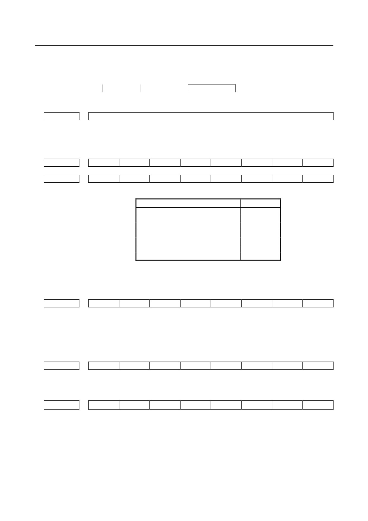
(2) Check CNC diagnosis data No. 0000, 1010. Check the items for which 1 is displayed at right side.
* Items with (a) to (d) relate with manual and automatic operation and its detail is shown below.
- 535 -
10.TROUBLESHOOTING
B-64485EN/01
(a) In-position check is being done
It shows that positioning is not yet completed. Check the following diagnosis data. (It is 1 in
the following condition)
DGN0300
Position Error > PARAM1826
In-position width
(i)
Check the parameters according to the parameter list.
1825
Servo loop gain per axis (Normal : 3000)
(b) Jog feedrate override is 0%
Check the signals using the PMC's signal status screen.
#7
#6
#5
#4
#3
#2
#1
#0
G0010
*JV7
*JV6
*JV5
*JV4
*JV3
*JV2
*JV1
*JV0
G0011
*JV15
*JV14
*JV13
*JV12
*JV11
*JV10
*JV9
*JV8
When the override is 0% all bits of the above address becomes
1111
1111 or 0000
0000.
*JV15
*JV0
Override
1111 1111 1111 1111
0.00%
1111 1111 1111 1110
0.01%
:
:
1101 1000 1110 1111
100.00%
:
:
0000 0000 0000 0001
655.34%
0000 0000 0000 0000
0.00%
(c) Interlock or start lock signal is input
There are a plural interlock signals. Check at first which interlock signal is used by the machine
tool builder at the parameters shown below.
#7
#6
#5
#4
#3
#2
#1
#0
3003
ITX
ITL
#0 (ITL) ITL=0 shows interlock signal *IT is effective. To 1)
#2 (ITX) ITX=0 shows interlock signal *ITn is effective. To 2)
Check state of effective interlock signals using the PMC's signal status screen.
(i)
Interlock signals (*IT, *CSL, and *BSL) are input.
#7
#6
#5
#4
#3
#2
#1
#0
G0008
*BSL
*CSL
*IT
*IT=0, *CSL=0, and *BSL=0 show that interlock signal is input.
(ii) Axis interlock signal (*ITn) is input.
#7
#6
#5
#4
#3
#2
#1
#0
G0130
*IT8
*IT7
*IT6
*IT5
*IT4
*IT3
*IT2
*IT1
*ITn=0 shows interlock signal is input.
(d) The NC is in the reset state.
In this state, "RESET" is display as the state indication of the previous item 1-(1)-(b). So, not
only manual operation but also all automatic operations are disabled. So, referring to the
Section "Manual and Automatic Operations are Disabled", make an investigation.
(e) The address to which an axis signal is assigned is incorrect.
The relationship between each CNC axis and PMC interface address is set in a parameter.
Check the setting of the following parameter:
- 536 -
B-64485EN/01
10.TROUBLESHOOTING
3021
Address to which an axis signal is assigned
2
When machine coordinate value does not update on position display
Machine lock signal (MLK) is input.
#7
#6
#5
#4
#3
#2
#1
#0
G0044
MLK
G0108
MLK8
MLK7
MLK6
MLK5
MLK4
MLK3
MLK2
MLK1
MLK : All axes machine lock
MLKn : Each axis machine lock
When the signal is 1, the corresponding machine lock signal is input.
10.3 JOG OPERATION CANNOT BE DONE
Points
(1) Check whether position display is operating.
(2) Check CNC status display.
(3) Check internal status using Diagnostic function.
Causes and Countermeasures
1
Position display (relative, absolute, machine coordinate) does not change
(1) Check mode selection status (JOG mode is not selected).
When status display shows JOG, it is normal.
When status display does not show JOG, mode select signal is not selected correctly. Confirm the
mode select signal using the PMC's signal status screen.
<Mode select signal>
#7
#6
#5
#4
#3
#2
#1
#0
G0043
MD4
MD2
MD1
↓
↓
↓
Manual operation (JOG) mode
1
0
1
(2) Feed axis and direction select signal is not input Check the signal using the PMC's signal status
screen.
#7
#6
#5
#4
#3
#2
#1
#0
G0100
+J8
+J7
+J6
+J5
+J4
+J3
+J2
+J1
G0102
-J8
-J7
-J6
-J5
-J4
-J3
-J2
-J1
When a bit is "1", the corresponding feed axis direction selection signal has been entered.
+
J
1
:
Feed along the 1st axis
:
8
:
Feed along the 8th axis
+
:
Feed in the + direction
-
:
Feed in the - direction
- 537 -
10.TROUBLESHOOTING
B-64485EN/01
Example)
In the normal state, pressing the "+X" button on the operator's panel causes the signal +Jn to be
displayed as "1".
* This signal becomes effective when the rise of the signal is detected. If, therefore, the direction
selection signal has been entered before jog mode selection, axis movement is not performed;
set the bit "0" and then re-check the signal.
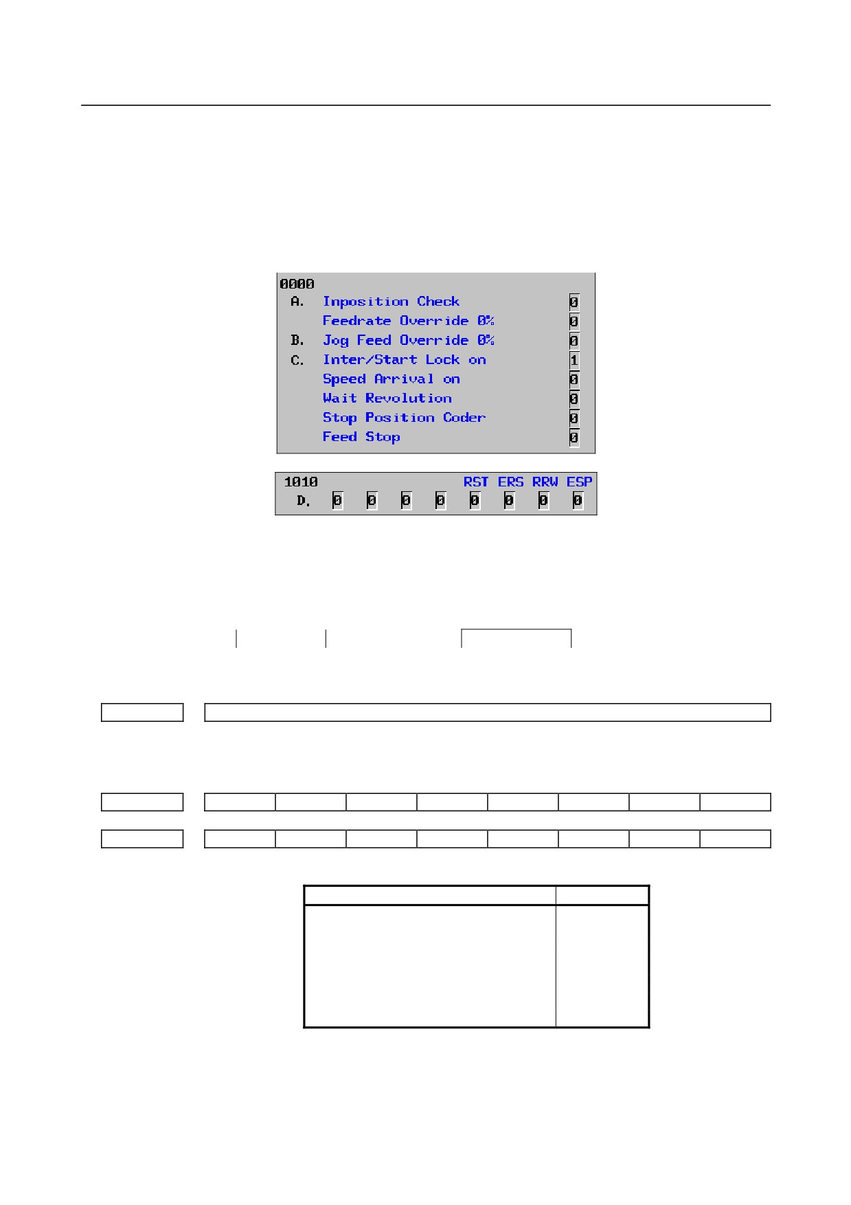
(3) Check CNC diagnosis data No. 0000, 1010. Check the items for which 1 is displayed at right side.
* Items with (a) to (d) relate with manual and automatic operation and its detail is shown below.
(a) In-position check is being done
It shows that positioning is not yet completed. Check the following diagnosis data. (It is 1 in
the following condition)
DGN0300
Position Error>Parameter No.1826
In-position width
(i)
Check the parameters according to the parameter list.
1825
Servo loop gain per axis (Normal : 3000)
(b) Jog feedrate override is 0%
Check the signals using the PMC's signal status screen.
#7
#6
#5
#4
#3
#2
#1
#0
G0100
*JV7
*JV6
*JV5
*JV4
*JV3
*JV2
*JV1
*JV0
G0011
*JV15
*JV14
*JV13
*JV12
*JV11
*JV10
*JV9
*JV8
When the override is 0% all bits of the above address becomes
1111
1111 or 0000
0000.
*JV15
*JV0
Override
1111 1111 1111 1111
0.00%
1111 1111 1111 1110
0.01%
:
:
1101 1000 1110 1111
100.00%
:
:
0000 0000 0000 0001
655.34%
0000 0000 0000 0000
0.00%
(c) Interlock or start lock signal is input
There are a plural interlock signals. Check at first which interlock signal is used by the machine
tool builder at the parameters shown below.
- 538 -
B-64485EN/01
10.TROUBLESHOOTING
#7
#6
#5
#4
#3
#2
#1
#0
3003
ITX
ITL
#0 (ITL) ITL=0 shows interlock signal *IT is effective. To 1)
#2 (ITX) ITX=0 shows interlock signal *ITn is effective. To 2)
Check state of effective interlock signals using the PMC's signal status screen.
(i)
Interlock signal (*IT) is input.
#7
#6
#5
#4
#3
#2
#1
#0
G0008
*IT
*IT=0 shows that interlock signal is input.
(ii) Axis interlock signal (*ITn) is input.
#7
#6
#5
#4
#3
#2
#1
#0
G0130
*IT8
*IT7
*IT6
*IT5
*IT4
*IT3
*IT2
*IT1
*ITn=0 shows interlock signal is input.
(d) NC is in a reset state
In this state, not only manual operation but also automatic operation is disabled. Make an
investigation according to the Section, "Manual Operation and Automatic Operation are
Disabled."
(4)
Jog feed rate setting (Parameter) is not correct.
1423
Jog feedrate per axis
(5)
Manual feed per revolution is selected
This function feeds an axis synchronized with spindle rotation and whether this function is used or
not is selected by the following parameter:
#7
#6
#5
#4
#3
#2
#1
#0
1402
JRV
JRV Jog feed and incremental feed are :
0 : Of feed per minute
1 : Of feed per revolution
(a) When parameter JRV is set to 1, feed rate of the axis is calculated by synchronizing with
rotation of the spindle. Therefore, rotate the spindle.
(b) If the axis does not move even when the spindle is rotated, check the detector of the spindle
(position coder) and the cable between the position coder and the CNC if it is short-circuited or
ungrounded.
(6)
The specified axis is the index table indexing axis. <machining center system only>
For the index table indexing axis (B-axis), jog feed, incremental feed, and manual handle feed
cannot be performed.
- 539 -
10.TROUBLESHOOTING
B-64485EN/01
10.4 HANDLE OPERATION CANNOT BE DONE
Points
If manual handle operation cannot be performed, the probable causes include the following:
• The servo is not activated.
• Manual pulse generators are not connected properly to the I/O module.
• The I/O Link i or I/O Link of the I/O module is not allocated, or is not allocated properly.
• A related input signal is not input due to a parameter setting error.
Also use CNC diagnosis functions to check the internal status.
Causes and Countermeasures
1
The servo is not activated
Check that the LED on the servo amplifier indicates "0". If a number other than "0" is indicated, the servo
is not activated. In this state, even JOG operation and automatic operation cannot be operated.
Check the servo-related parameters and the wiring.
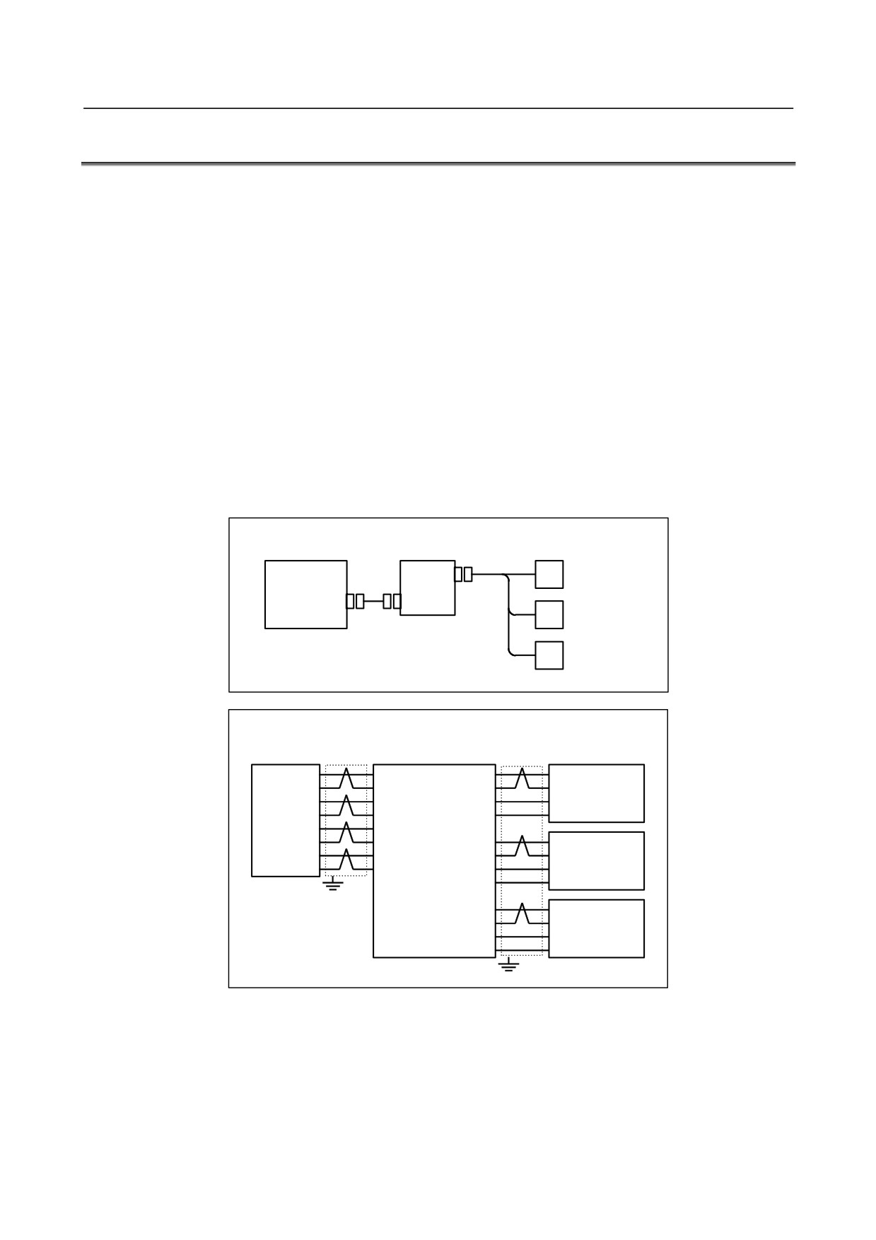
2 Checking the manual pulse generators
(1) Cable failures (such as breaks)
Examine the cables for faults such as breaks and short-circuits, referring to the figure below.
CNC
Distributed I/O module
(Main board)
Operator's panel I/O module
First manual pulse
JA3
#1
generator
IOLINK
(JD1A)
JD1B
Second manual
#2
pulse generator
Third manual pulse
#3
generator
CNC
Distributed I/O module
Manual pulse
(Main board)
Operator's panel I/O module
generators
JD1A
Shield
JD1B
JA3
Shield
SIN(01)
(03)SOUT
HA1(01)
HA1
*SIN(02)
(04)*SOUT
HB1(02)
HB1
First
SOUT(03)
(01)SIN
+5V(09)
+5V
*SOUT(04)
(02)*SIN
0V(12)
0V
0V(11)
(11)0V
0V(12)
(12)0V
HA2(03)
HA2
0V(13)
(13)0V
HB2(04)
HB2
Second
0V(14)
(14)0V
+5V(18)
+5V
0V(14)
0V
HA3(05)
HA3
HB3(06)
HB3
Third
+5V(20)
+5V
0V(16)
0V
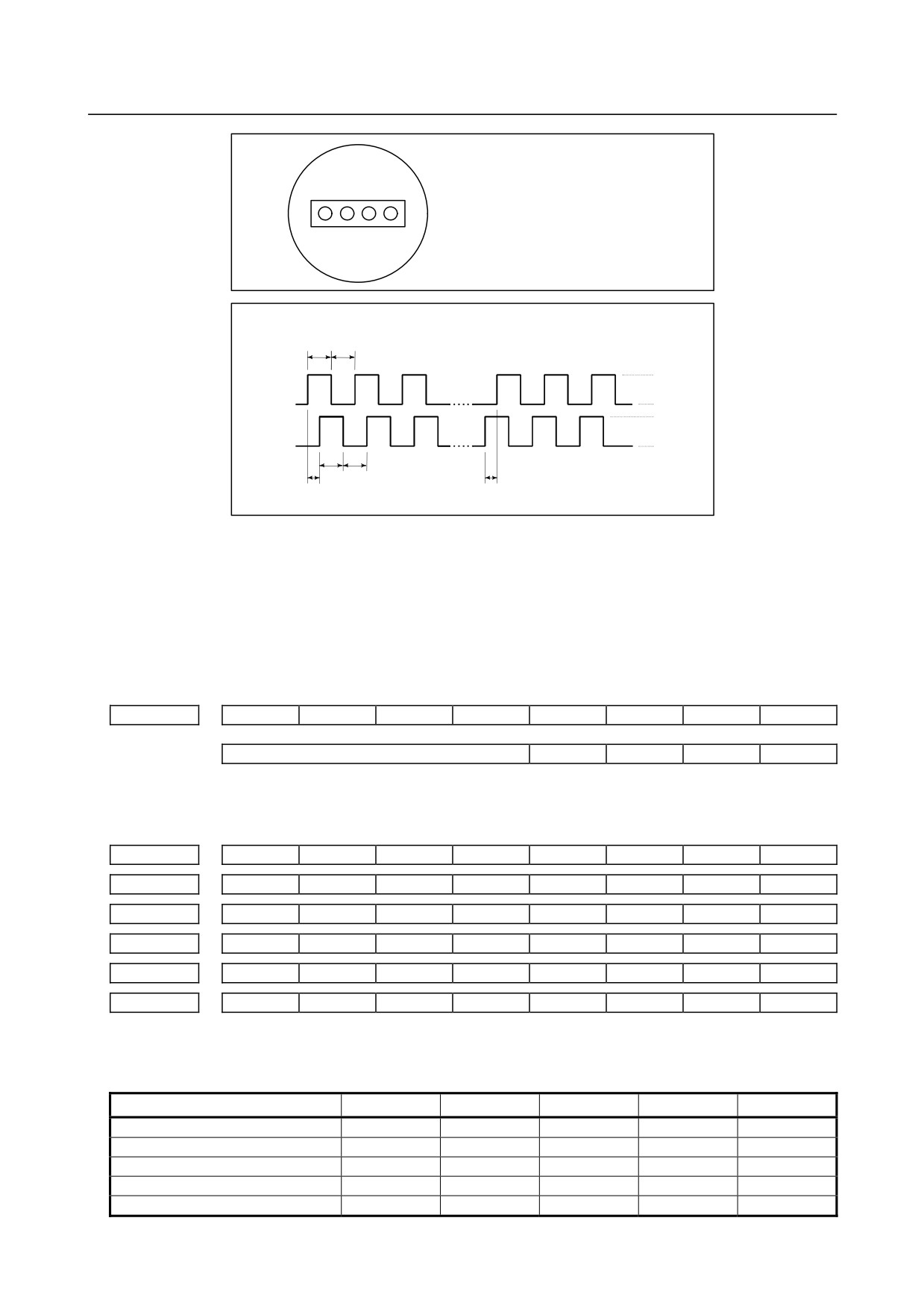
(2) Manual pulse generator failures
When rotated, a manual pulse generator generates the signals shown below.
Using an oscilloscope, measure the signals from the screw terminal block located at the rear of a manual
pulse generator. If no signals are output, measure the +5 V voltage.
- 540 -
B-64485EN/01
10.TROUBLESHOOTING
Rear of a manual pulse generator
Screw
terminal
block
HA: Manual pulse generator phase A signal
HB: Manual pulse generator phase B signal
+5V 0V HA HB
When rotated in the plus direction
When rotated in the minus direction
1 : 1
+5V
HA
On
Off
On
Off
0V
+5V
HB
On
Off
On
Off
0V
1 : 1
1/4
1/4 (phase difference)
Check the on/off ratio and the phase difference between HA and HB.
3
Checking the parameters and input signals
See Section “CNC STATE DISPLAY.”
(1) Check CNC status display at lower left corner of the screen.
When the status display shows HND, mode selection is correct.
If it is not HND, mode select signal is not input correctly. Check the mode select signal using the PMC's
signal status screen.
#7
#6
#5
#4
#3
#2
#1
#0
G0043
MD4
MD2
MD1
↓
↓
↓
Manual handle mode
1
0
0
(2) Manual handle feed axis select signal is not input.
Check the signals using the PMC's signal status screen.
#7
#6
#5
#4
#3
#2
#1
#0
G0018
HS2D
HS2C
HS2B
HS2A
HS1D
HS1C
HS1B
HS1A
G0019
HS3D
HS3C
HS3B
HS3A
G0020
HS4D
HS4C
HS4B
HS4A
G0379
HS5D
HS5C
HS5B
HS5A
G0411
HS4E
HS3E
HS2E
HS1E
G0412
HS5E
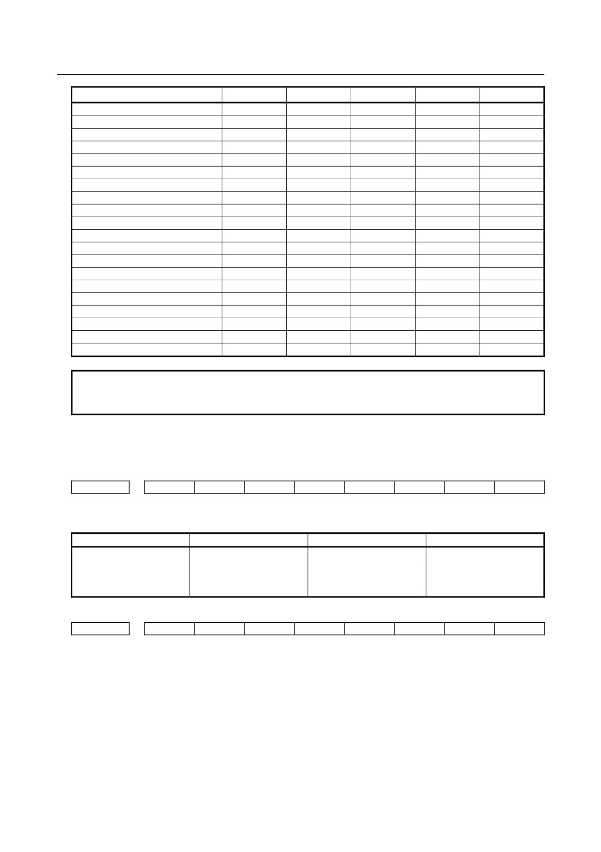
When axis select switch for manual handle feed is selected on the machine operator's panel, if the signals
are input as follows, it is normal.
Selected axis
HSnE
HSnD
HSnC
HSnB
HSnA
no selection
0
0
0
0
0
1st axis
0
0
0
0
1
2nd axis
0
0
0
1
0
3rd axis
0
0
0
1
1
4th axis
0
0
1
0
0
- 541 -
10.TROUBLESHOOTING
B-64485EN/01
Selected axis
HSnE
HSnD
HSnC
HSnB
HSnA
5th axis
0
0
1
0
1
6th axis
0
0
1
1
0
7th axis
0
0
1
1
1
8th axis
0
1
0
0
0
9th axis
0
1
0
0
1
10th axis
0
1
0
1
0
11th axis
0
1
0
1
1
12th axis
0
1
1
0
0
13th axis
0
1
1
0
1
14th axis
0
1
1
1
0
15th axis
0
1
1
1
1
16th axis
1
0
0
0
0
17th axis
1
0
0
0
1
18th axis
1
0
0
1
0
19th axis
1
0
0
1
1
20th axis
1
0
1
0
0
21st axis
1
0
1
0
1
22nd axis
1
0
1
1
0
23rd axis
1
0
1
1
1
24th axis
1
1
0
0
0
NOTE
In the above table, n is the number of the manual pulse generator (MPG) and up
to 5 MPGs can be used. A feed axis is selected by 4-bit code of A to E.
(3) Manual handle feed multiplication is not correct
Check the following signals using the PMC's signal status screen. Also confirm the following parameters
based on the parameter list.
#7
#6
#5
#4
#3
#2
#1
#0
G0019
MP2
MP1
In handle mode, the travel distance per step can be changed.
MP2
MP1
Step feed
Handle feed
0
0
×
1
×
1
0
1
×
10
×
10
1
0
×
100
× Mn
1
1
× 1000
× Nn
#7
#6
#5
#4
#3
#2
#1
#0
7100
MPX
#5 MPX In Manual handle feed mode, manual handle feed amount selection signal is
0 : same for all manual pulse generator, and it is set by signals MP1 and
MP2<Gn019.4,.5>.
1 : differ to each other manual pulse generator, and it’s setting signal as follow:
1st Manual Pulse Generator : MP1,MP2<Gn019.4,.5>
2nd Manual Pulse Generator : MP21,MP22<Gn087.0,.1>
3rd Manual Pulse Generator : MP31,MP32<Gn087.3,.4>
4th Manual Pulse Generator : MP41,MP42<Gn087.6,.7>
5th Manual Pulse Generator : MP51,MP52<Gn380.0,.1>
- 542 -
B-64485EN/01
10.TROUBLESHOOTING
#7
#6
#5
#4
#3
#2
#1
#0
7102
HNGx
#0 HNGx Axis movement direction for rotation direction of manual pulse generator
0: Same in direction
1: Reverse in direction
7113
Manual handle feed magnification m
7114
Manual handle feed magnification n
7131
Manual handle feed magnification m2 / 2nd. manual pulse generator
7132
Manual handle feed magnification n2 / 2nd. manual pulse generator
7133
Manual handle feed magnification m3 / 3rd. manual pulse generator
7134
Manual handle feed magnification n3 / 3rd. manual pulse generator
7135
Manual handle feed magnification m4 / 4th. manual pulse generator
7136
Manual handle feed magnification n4 / 4th. manual pulse generator
7137
Manual handle feed magnification m5 / 5th. manual pulse generator
7138
Manual handle feed magnification n5 / 5th. manual pulse generator
(4) The specified axis is the index table indexing axis. <machining center system only>
For the index table indexing axis (B-axis), jog feed, incremental feed, and manual handle feed cannot be
performed.
4
Checking the CNC diagnosis functions
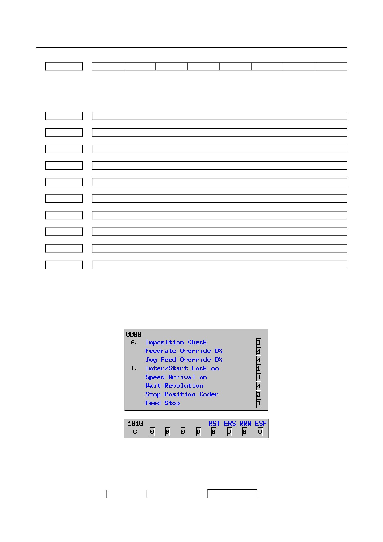
(1) Check CNC diagnosis data No. 0000, 1010. Check the items for which 1 is displayed at right side.
* Items with (a) to (c) relate with manual and automatic operation and its detail is shown below.
(a) In-position check is being done
It shows that positioning is not yet completed. Check the following diagnosis data. (It is 1 in
the following condition)
DGN0300
Position Error>Parameter No.1826
In-position width
- 543 -
10.TROUBLESHOOTING
B-64485EN/01
(i)
Check the parameters according to the parameter list.
1825
Servo loop gain per axis (Normal : 3000)
(b) Interlock or start lock signal is input
There are a plural interlock signals. Check at first which interlock signal is used by the machine
tool builder at the parameters shown below.
#7
#6
#5
#4
#3
#2
#1
#0
3003
ITX
ITL
#0 (ITL) ITL=0 shows interlock signal *IT is effective. To 1)
#2 (ITX) ITX=0 shows interlock signal *ITn is effective. To 2)
Check state of effective interlock signals using the PMC's signal status screen.
(i)
Interlock signal (*IT) is input.
#7
#6
#5
#4
#3
#2
#1
#0
G0008
*IT
*IT=0 shows that interlock signal is input.
(ii) Axis interlock signal (*ITn) is input.
#7
#6
#5
#4
#3
#2
#1
#0
G0130
*IT8
*IT7
*IT6
*IT5
*IT4
*IT3
*IT2
*IT1
*ITn=0 shows interlock signal is input.
(c) NC is in a reset state
In this state, not only manual operation but also automatic operation is disabled. Make an
investigation according to the Section, "Manual Operation and Automatic Operation are
Disabled."
10.5 AUTOMATIC OPERATION CANNOT BE DONE
Points
(1) Check manual operation is possible.
(2) Check the status of cycle start LED on machine operator's manual.
(3) Check status of CNC.
Causes and Countermeasures
When manual operation is either impossible, perform countermeasure, based on the Section, "Jog
Operation cannot be done".
Confirm that a correct mode is selected according to the mode select status of CNC status display. Also,
by confirming the automatic operation status it is possible to identify cycle operation, feed hold and cycle
stop state.
1
When cycle operation is not started (Cycle start LED does not light)
"****" is displayed at status display on screen.
(1) Mode select signal is not correct.
When the mode select signal is input correctly, following status display is done.
MDI
:
Manual data input mode (MDI)
MEM :
Memory operation mode
RMT
:
Remote operation mode
If status display does not show a correct status, check the mode signal with following PMC's signal
status screen.
- 544 -
B-64485EN/01
10.TROUBLESHOOTING
#7
#6
#5
#4
#3
#2
#1
#0
G0043
DNCI
MD4
MD2
MD1
DNCI
MD4
MD2
MD1
Mode select
-
0
0
0
Manual data input (MDI) mode
0
0
0
1
Automatic operation (MEM) mode
1
0
0
1
Remote operation mode
(2) Cycle start signal is not input
This signal turns 1 when cycle start button is pressed and turns 0 when it is released. The cycle start
actuates when it changes from 1 to 0. Check the state of the signal using PMC's diagnosis
function(PMCDGN).
#7
#6
#5
#4
#3
#2
#1
#0
G0007
ST
ST :
Cycle start signal
(3) Feed hold signal is input
Under normal state, the feed hold signal is 1 when the feed hold button is not pressed.
Check the state of this signal using the PMC's diagnosis function (PMCDGN).
#7
#6
#5
#4
#3
#2
#1
#0
G0008
*SP
*SP :
Feed hold signal
2
When an automatic operation is in progress (Cycle start LED is lit)
CNC's status display shows "STRT" on the screen.
(1) Check information displayed at CNC diagnosis data No. 0. Check the items for which 1 is displayed
at the right side.
Diagnosis
0
CNC internal state 1
[Data type] Bit
NAME
Internal state when "1" is displayed
a
INPOSITION CHECK
In-position check is being done.
b
FEEDRATE OVERRIDE 0% Feedrate override is 0%.
c
JOG FEED OVERRIDE 0% Jog feedrate override is 0%.
d
INTER/START LOCK ON Interlock/start lock is on.
e
SPEED ARRIVAL ON
The system is waiting for the speed arrival signal to
turn on.
WAIT REVOLUTION
The system is waiting for the spindle one-rotation
signal in threading.
STOP POSITION OCDER The system is waiting for the rotation of the position
coder in spindle feed per revolution.
FEED STOP
A feed stop was made.
* Items with a to e relate with an automatic operation and their details are as follows :
(a) In-position check (confirming positioning) is being done
Positioning (G00) to a specified position of a specified axis is not completed.
Whether positioning is completed or not is checked as the servo position error
amount. Check it diagnosis data as follows:
Diagnosis 300
Position error > Parameter No. 1826
In-position width
Position error amount almost becomes
0, when positioning of an axis
completes and when the amount becomes within the in-position width, it is
assumed that positioning completes and the next block is executed.
- 545 -
10.TROUBLESHOOTING
B-64485EN/01
(b) Feedrate override is at 0%
Actual feedrate is overridden by the override signals to a programmed feedrate.
Check the override signals using the PMC's signal status screen.
• Normal override signal
#7
#6
#5
#4
#3
#2
#1
#0
G0012
*FV7
*FV6
*FV5
*FV4
*FV3
*FV2
*FV1
*FV0
*FVn : Feedrate override
<2nd override signal (option)>
Feed rate is overridden more finely using the signals below:
See MTB's manual whether this feature is equipped.
#7
#6
#5
#4
#3
#2
#1
#0
G0013
*AFV7
*AFV6
*AFV5
*AFV4
*AFV3
*AFV2
*AFV1
*AFV0
*AFVn :
2nd feed rate override
• State of override signal
*FV7
*FV0
*AFV7 . . . *AFV0
1 1 1 1 1 1 1 1
0%
1 1 1 1 1 1 1 1
0%
1 1 1 1 1 1 1 0
1%
1 1 1 1 1 1 1 0
1%
:
:
:
:
1 0 0 1 1 0 1 1
100%
1 0 0 1 1 0 1 1
100%
:
:
:
:
0 0 0 0 0 0 0 1
254%
0 0 0 0 0 0 0 1
254%
0 0 0 0 0 0 0 0
0%
0 0 0 0 0 0 0 0
0%
(c) Manual feedrate override is 0% (dry run)
Normally manual feedrate override function is used for jog feed.
But when DRN(dry run) signal turns on during an automatic operation, override values set with
these signals become valid to the following speed set by a parameter.
#7
#6
#5
#4
#3
#2
#1
#0
G0046
DRN
Dry run signal is input with this signal being 1.
1410
Dry run rate
The rate when the following override value is 100%.
#7
#6
#5
#4
#3
#2
#1
#0
G0010
*JV7
*JV6
*JV5
*JV4
*JV3
*JV2
*JV1
*JV0
G0011
*JV15
*JV14
*JV13
*JV12
*JV11
*JV10
*JV9
*JV8
When override value is 0%, all bits of the above address is
[1111
1111] or [0000
0000].
*JV15
*JV0
Override
1111 1111 1111 1111
0.00%
1111 1111 1111 1110
0.01%
:
:
1101 1000 1110 1111
100.00%
:
:
0000 0000 0000 0001
655.34%
0000 0000 0000 0000
0.00%
- 546 -
B-64485EN/01
10.TROUBLESHOOTING
(d) Interlock signal is input
There are a plural number of interlock functions. Parameters are set by machine tool builders
for which interlock function is used.
Therefore, confirm the following parameters at first:
#7
#6
#5
#4
#3
#2
#1
#0
3003
ITX
ITL
ITL 0: Interlock signal(*IT) is valid.
ITX 0: Interlock signal (*ITn) is valid.
Confirm which interlock signal is activated by the PMC's signal status screen.
(i)
Interlock signals (*IT, *CSL, and *BSL) are input.
#7
#6
#5
#4
#3
#2
#1
#0
G0008
*BSL
*CSL
*IT
*IT=0, *CSL=0, and *BSL=0 show that interlock signal is input.
(ii) Interlock signal per each axis (*ITn) is input
#7
#6
#5
#4
#3
#2
#1
#0
G0130
*IT8
*IT7
*IT6
*IT5
*IT4
*IT3
*IT2
*IT1
*ITn When the bit is 0, the corresponding axis's interlock signal is input.
(iii) Controlled axis detach function is running. A detached axis is specified for travelling.
* This function is valid when bit 7 (RMBx) of CNC parameter No. 1005=1. For whether
this function is running or not, confirm the following signal using the PMC's signal status
screen. Check the axis concerned.
1)
The control axis detach signal (DTCHn) is input.
#7
#6
#5
#4
#3
#2
#1
#0
G0124
DTCH8
DTCH7
DTCH6
DTCH5
DTCH4
DTCH3
DTCH2
DTCH1
DTCHn If it is 1, the corresponding axis is detached.
2)
The following parameter enables the control axis detach function to the corresponding
axis.
#7
#6
#5
#4
#3
#2
#1
#0
0012
RMVx
RMVx Releasing the assignment of the control axis for each axis
0: Not released
1: Released
(Equivalent to the control axis detachment signals DTCH1, DTCH2, and so forth)
(e) CNC is waiting for spindle speed arrival signal to be input
Actual spindle speed does not arrive at a speed specified in a program.
Confirm the signal state using the PMC's signal status screen.
#7
#6
#5
#4
#3
#2
#1
#0
G0029
SAR
When this signal is 0, spindle speed does not arrive at the specified speed.
* This function is valid when the bit 0 (SAR) of parameter No. 3708=1.
- 547 -
10.TROUBLESHOOTING
B-64485EN/01
(2) Only rapid traverse in positioning (G00) does not function Confirm the following parameter and
signals from the PMC.
(a) Setting value of rapid traverse rate
1420
Rapid traverse rate per axis
(b) Rapid traverse override signals
#7
#6
#5
#4
#3
#2
#1
#0
G0014
ROV2
ROV1
G0096
HROV
*HROV6
*HROV5
*HROV4
*HROV3
*HROV2
*HROV1
*HROV0
(HROV-0)
(HROV=1)
ROV1
ROV2
Override
*HROV6 . . . *HROV0
Override
0
0
100%
1 1 1 1 1 1 1
0%
1
1
50%
1 1 1 1 1 1 0
1%
0
1
25%
:
:
1
1
F0
0 0 1 1 0 1 1
100%
1421
Rapid traverse override F0 rate
(3)
Only feed (other than G00) does not function
(a)
Maximum feedrate set by parameter is incorrect.
Feedrate (other than G00) is clamped at this upper feedrate.
1430
Maximum feedrate in each axis
(b)
Feedrate is specified by feed per revolution (mm/rev)
(i)
Position coder does not rotate
Check the connection between spindle and position coder
The following failure is considered:
- Timing belt is broken
- Key is removed
- Coupling is loose
- Connector of signal cable is loosened
(ii) Position coder is faulty
(c)
Thread cutting does not operate
(i)
Position coder does not rotate
Check the connection between spindle and position coder
The following failure is considered:
- Timing belt is broken
- Key is removed
- Coupling is loose
- Connector of signal cable is loosened
(ii) Position coder is faulty
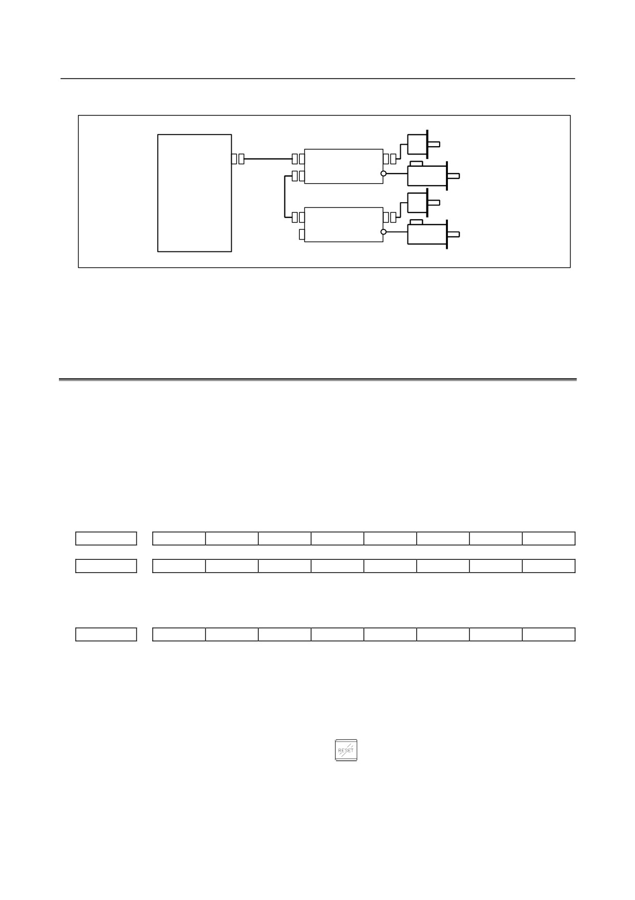
Position coder is connected to the spindle amplifier when serial interface spindle is used or
connected to the CNC when analog interface spindle is used.
For details of connection, refer to the following.
Whether A/B phase signals from the position coder are read correctly, can be judged also by
the spindle speed display on the screen (position screen).
(However, it is not displayed when bit 2 (DPS) of parameter No. 3105 is set to 0).
- 548 -
B-64485EN/01
10.TROUBLESHOOTING
• αi series spindle amplifier
CNC
Position coder
JA7B
JYA3
JA41
SPM
JA7A
Spindle motor
Position coder
JA7B
JYA3
SPM
JA7A
Spindle motor
(d) A cutting feed block containing a feedrate command (F command) with a feedrate of 0 is
specified.
If the bit
7 (FCO) of parameter No.
1404 is set to
1, alarm PS0011,
“FEED ZERO
(COMMAND)” is not issued even if a feedrate command (F command) with a feedrate of 0 is
issued.
10.6 CYCLE START LED SIGNAL HAS TURNED OFF
Points
(1) After cycle operation is started, then stopped, check as follows:
(2) Confirm cycle start LED on machine operator's panel.
(3) Confirm CNC's diagnosis function.
Causes and Countermeasures
Check the states of the related signals on the signal status screen of PMC.
a. Emergency stop is input
#7
#6
#5
#4
#3
#2
#1
#0
X0008
*ESP
G0008
*ESP
*ESP=0 Emergency stop signal is input :
b. External reset signal is input
#7
#6
#5
#4
#3
#2
#1
#0
G0008
ERS
#7(ERS) When the bit is 1, external reset signal is input.
* This signal is usually used for a confirmation signal of M02 when an M02 is specified in a program
as the end of a program.
Therefore, when M02 is executed, this signal is input.
c. Reset button on the MDI is pressed
An automatic operation is put into a reset status when
key on the MDI panel is pressed.
- 549 -
10.TROUBLESHOOTING
B-64485EN/01
d. Reset & rewind signal is input
#7
#6
#5
#4
#3
#2
#1
#0
G0008
RRW
#6(RRW) When this signal is 1, the reset & rewind signal is input.
* This signal is usually used for a confirmation signal of M30 when an M30 is specified in a program
as the end of a program.
Therefore, when M30 is executed, this signal is input.
e. Servo alarm has generated
When any servo alarm has generated, cycle operation is put into the reset state and operation stop.
f.
Cycle operation is in a feed hold state
The cycle operation becomes feed hold state in the following cases:
(1) Modes are switched from an automatic operation mode to a manual operation mode.
(2) Feed hold signal is input.
• Mode select signal
#7
#6
#5
#4
#3
#2
#1
#0
G0043
MD4
MD2
MD1
↓
↓
↓
Memory edit (EDIT)
0
1
1
Automatic
Automatic operation (AUTO)
0
0
1
operation
Manual data input (MDI)
0
0
0
Jog feed (JOG)
1
0
1
Handle/step
1
0
0
Manual operation
TEACH IN HANDLE
1
1
1
TEACH IN JOG
1
1
0
• Feed hold signal
#7
#6
#5
#4
#3
#2
#1
#0
G0008
*SP
#5(*SP) When this signal is 0, the feed hold signal is input.
g. It become single block stop during automatic operation
#7
#6
#5
#4
#3
#2
#1
#0
G0046
SBK
#1(SBK) When this signal is 1, the single block signal is input.
10.7 NOTHING IS DISPLAYED ON THE LCD WHEN THE
POWER IS TURNED ON
Causes and Countermeasures
If nothing is displayed on the LCD at power-up or if the LCD is locked with "LOADING GRAPHIC
SYSTEM", the probable causes include the following:
-
For the LCD-mounted type
• The LCD cable or backlight cable is not connected.
• The necessary software is not installed.
• The main board, display control card, CPU card, or inverter board is defective.
- 550 -
B-64485EN/01
10.TROUBLESHOOTING
-
For the stand-alone type
• The LCD unit is not connected to the power supply.
• The LCD cable or backlight cable is not connected.
• The LCD unit is not connected to the CNC with the optical cable or the cable is broken.
• The necessary software is not installed.
• The main board, display control card, or LCD unit is defective.
If “LOADING GRAPHIC SYSTEM” is displayed on a 15” display for the 30i/31i/32i, this indicates that
the display control circuit has started up normally, but the CNC has not started up or communication with
the CNC has not been established.
-
LED display
Check which LED lights on the main board while referencing the item “LED display” of the main board.
If the main board has started up normally and the LED display indicates normal operation, a probable
cause is a fault of the display system, such as a cable not connected or a defective inverter board.
If the LED display is locked in the middle of the startup process, the probable causes include defective
hardware (or installation failure) and the necessary software not installed.
-
Connection of the LCD and backlight cables
Check that the LCD and backlight cables are connected firmly to the corresponding connectors.
These cables are connected before shipment from FANUC. This check is, however, required because the
cables may be disconnected during maintenance.
-
The necessary software is not installed
If necessary software is not stored in the FROM module, the CNC may not start up.
-
Defective printed circuit board
If the main board or display control card is defective or is not correctly installed, the CNC may not start
up.
Check that the card PCBs are engaged firmly with the connectors on the main board.
If any of the above actions does not solve the problem, replace the display control card, CPU card, and
main board.
-
Installation positions of the display control card and CPU card
Referring to Section, “MOUNTING AND DEMOUNTING CARD PCBS,” check the installation status.
10.8 INPUT FROM AND OUTPUT TO I/O DEVICES CANNOT BE
PERFORMED, INPUT/OUTPUT CANNOT BE PERFORMED
PROPERLY
Causes and Countermeasures
If the I/O Link i or I/O Link is not established, if the signals from an I/O device cannot be input normally
to the CNC, or if the signals from the CNC cannot be output to an I/O device, the probable causes include
the following:
• The I/O device is not turned on, or the power supply is not at the appropriate voltage.
• The I/O Link i or I/O Link cable is not connected correctly or appropriately.
• The grounding is not correct.
• The input/output signals are not connected correctly.
• I/O Link i or I/O Link allocation is not performed, or is not performed properly.
- 551 -