FANUC Series 30i-MODEL B, 31i-MODEL B, 32i-MODEL B. MAINTENANCE MANUAL - page 14
6.INTERFACE BETWEEN CNC AND PMC
B-64485EN/01
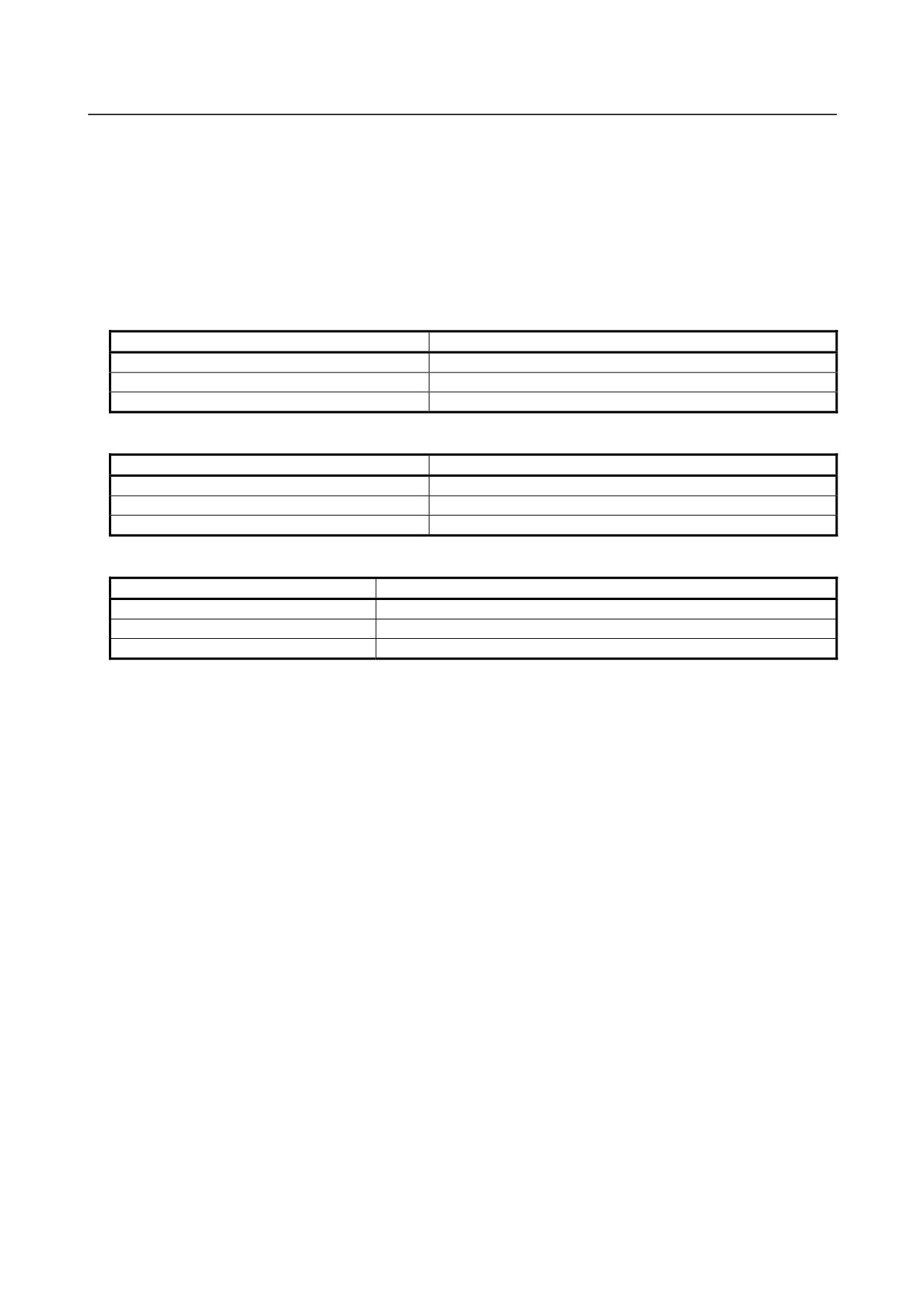
ID
Displayed I/O Unit
C7
I/O FOR OP. PANEL (DCS)_S
C8
SAFETY IO UNIT
D0
I/O UNIT-MODEL A
D8
I/O UNIT-MODEL B
D9
HANDY MACHINE OP. PANEL
Soft keys
Displays connection status of
Deletes I/O devices
the next channel
configuration
Displays connection status of
Registers I/O devices
the previous channel
configuration
6.5.9
Signal Trace Function ([TRACE] Screen)
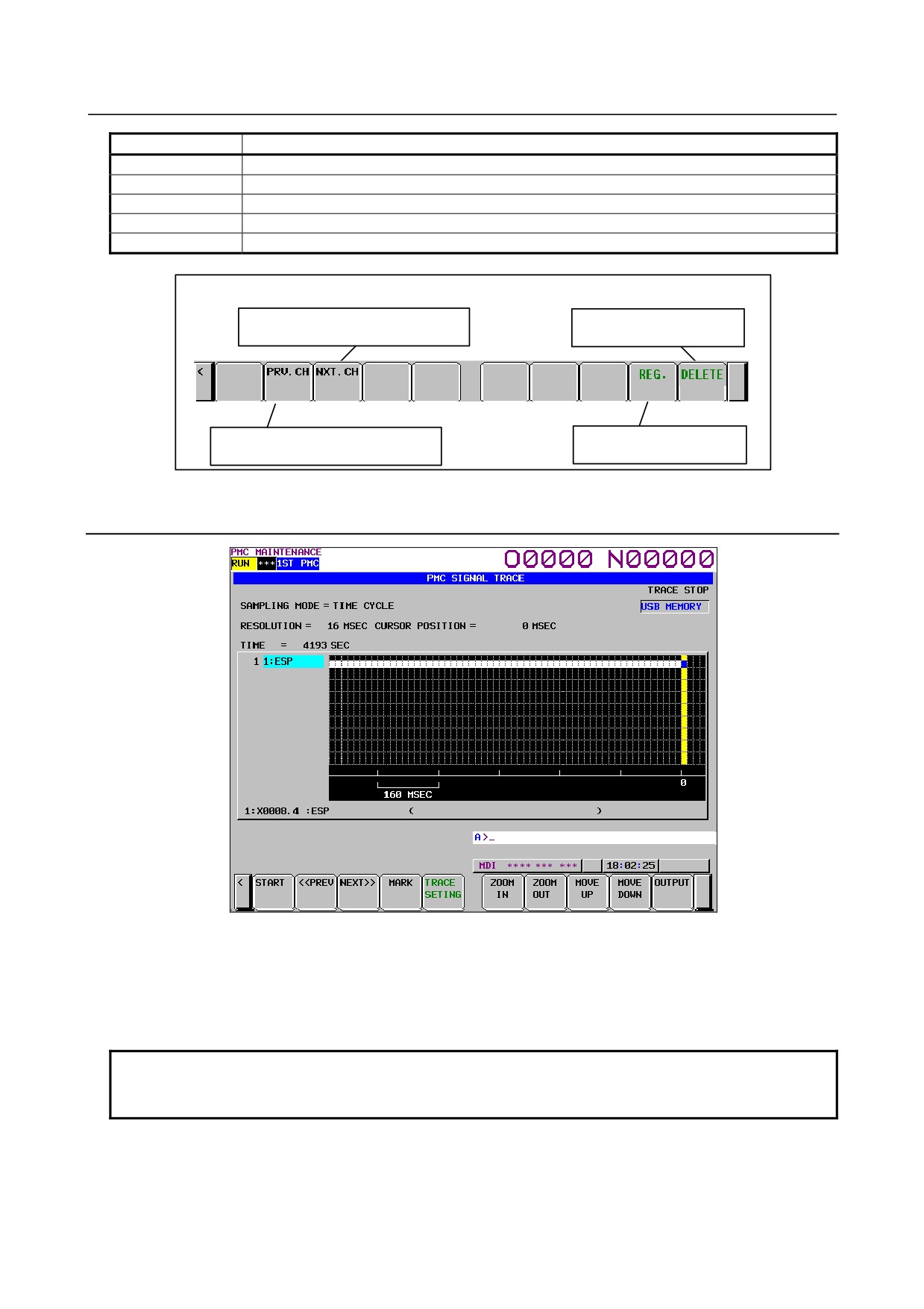
Fig. 6.5.9 (a) Signal trace screen (initial screen)
Before trace operation can be executed, the trace parameters must be set. Press the soft key [TRACE
SETING] to switch the screen display to the trace parameter setting screen.
By setting the PMC setting screen, the trace function can be automatically started after the power is
turned on. In this case as well, the trace parameters must be set beforehand.
NOTE
For the setting to automatically start the trace function after the power is turned
on, see Subsection 7.5.11.2.
- 372 -
B-64485EN/01
6.INTERFACE BETWEEN CNC AND PMC
6.5.10 Setting of Trace Parameter ([TRACE SETING] Screen)
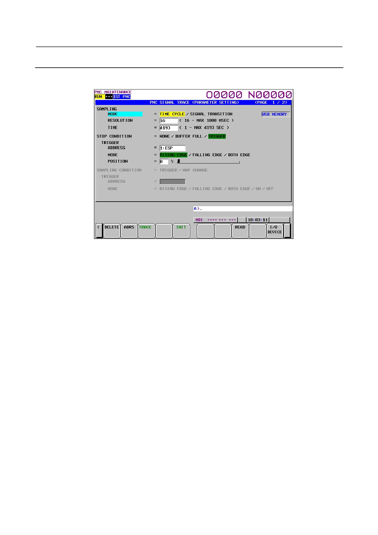
On the trace parameter setting screen, a sampling condition can be set. The screen consists of two pages.
Use the page keys to switch between the pages.
Fig. 6.5.10 (a) Trace parameter setting screen (first page)
(a)
SAMPLING/ MODE
Determines the sampling mode.
•
TIME CYCLE:
Samples at every specified cycle time.
•
SIGNAL TRANSITION:
Monitors the signal at a set cycle and samples when the signal
makes a transition.
(b)
SAMPLING/ RESOLUTION
The resolution of sampling is inputted. The default value is the minimum sampling resolution (msec),
which varies depending on the CNC.
Setting range: Minimum sampling resolution to 1000 (msec)
An input value is rounded off to a multiple of the minimum sampling resolution (msec) which is
closest to but not greater than the input value.
(c)
SAMPLING/ TIME
This parameter is displayed when "TIME CYCLE" is set on "SAMPLING/ MODE". The execution
time of trace is inputted. The value of "SAMPLING/ RESOLUTION" or the number of specified
signal address changes the range of the value that is able to input. The range is displayed on the right
side.
(d)
SAMPLING/ FRAME
This parameter is displayed when "SIGNAL TRANSITION" is set on SAMPLING/ MODE". The
number of sampling is inputted. The value of "SAMPLING/ RESOLUTION" or the number of
specified signal addresses changes the range of the value that is able to input. The range is displayed
on the right side.
(e)
STOP CONDITION
Determines the condition to stop the trace.
•
NONE: Does not stop the tracing automatically.
•
BUFFER FULL: Stops the tracing when the buffer becomes full.
•
TRIGGER:
Stops the tracing by trigger.
(f)
STOP CONDITION/ TRIGGER/ ADDRESS
When "TRIGGER" is set on "STOP CONDITION", this parameter is enabled. Input signal address
or symbol name as stop trigger.
A PMC number can be set for a trigger address by entering the PMC number at the time of address
setting.
- 373 -

6.INTERFACE BETWEEN CNC AND PMC
B-64485EN/01
Example: "2:R9200.1" + Input key
A setting can be made by entering "PMC number" + ":" + "address" as indicated above.
(g) STOP CONDITION/ TRIGGER/ MODE
When "TRIGGER" is set on "STOP CONDITION", this parameter is enabled. Determine the trigger
mode when the trace is stopped.
•
RISING EDGE:
Stops the tracing automatically by rising up of the trigger signal.
•
FALLING EDGE:
Stops the tracing automatically by falling down of the trigger signal.
•
BOTH EDGE:
Stops the tracing automatically by rising up or falling down of the trigger
signal.
(h) STOP CONDITION/ TRIGGER/ POSITION
When "TRIGGER" is set on "STOP CONDITION", this parameter is enabled. Input the ratio of the
sampling time or number which specifies the position where specified trigger condition is on. If you
would like to examine the transitions of the signal before the trigger condition, you should set a big
value in this parameter. If you would like to examine the transitions of the signal after the trigger
condition, you should set a small value in this parameter.
Example: The case that sampling time is 10 seconds and trigger position is set as "10%".
Trigger position
← 1 sec →←
9 sec
→
(i)
SAMPLING CONDITION
When "SIGNAL TRANSITION" is set on "TRACE MODE", this parameter is enabled.
Determine the sampling condition.
•
TRIGGER:
Samples the status of specified signals when the specified sampling
condition is on.
•
ANY CHANGE: Samples the status of specified signals when the signals change.
(j)
SAMPLING CONDITION/ TRIGGER/ ADDRESS
When "SIGNAL TRANSITION" is set on "TRACE MODE", and "TRIGGER" is set on
"SAMPLING CONDITION", this parameter is enabled. Input signal address or symbol name as
sampling trigger.
A PMC number can be set for a trigger address by entering the PMC number at the time of address
setting.
Example: "2:R9200.1" + Input key
A setting can be made by entering "PMC number" + ":" + "address" as indicated above.
(k)
SAMPLING CONDITION/ TRIGGER/ MODE
When "SIGNAL TRANSITION" is set on "TRACE MODE", and "TRIGGER" is set on
"SAMPLING CONDITION", this parameter is enabled. Input trigger mode that determines the
condition of specified trigger.
•
RISING EDGE: Samples the status of specified signals by rising up of the trigger signal.
•
FALLING EDGE: Samples the status of specified signals by falling down of the trigger
signal.
•
BOTH EDGE: Trigger signal.
•
ON:
Samples the status of specified signals during the trigger signal is on.
•
OFF:
Samples the status of specified signals during the trigger signal is off.
In page 2 of the Parameter Setting screen, you can set the addresses or symbols that should be
sampled.
- 374 -
B-64485EN/01
6.INTERFACE BETWEEN CNC AND PMC
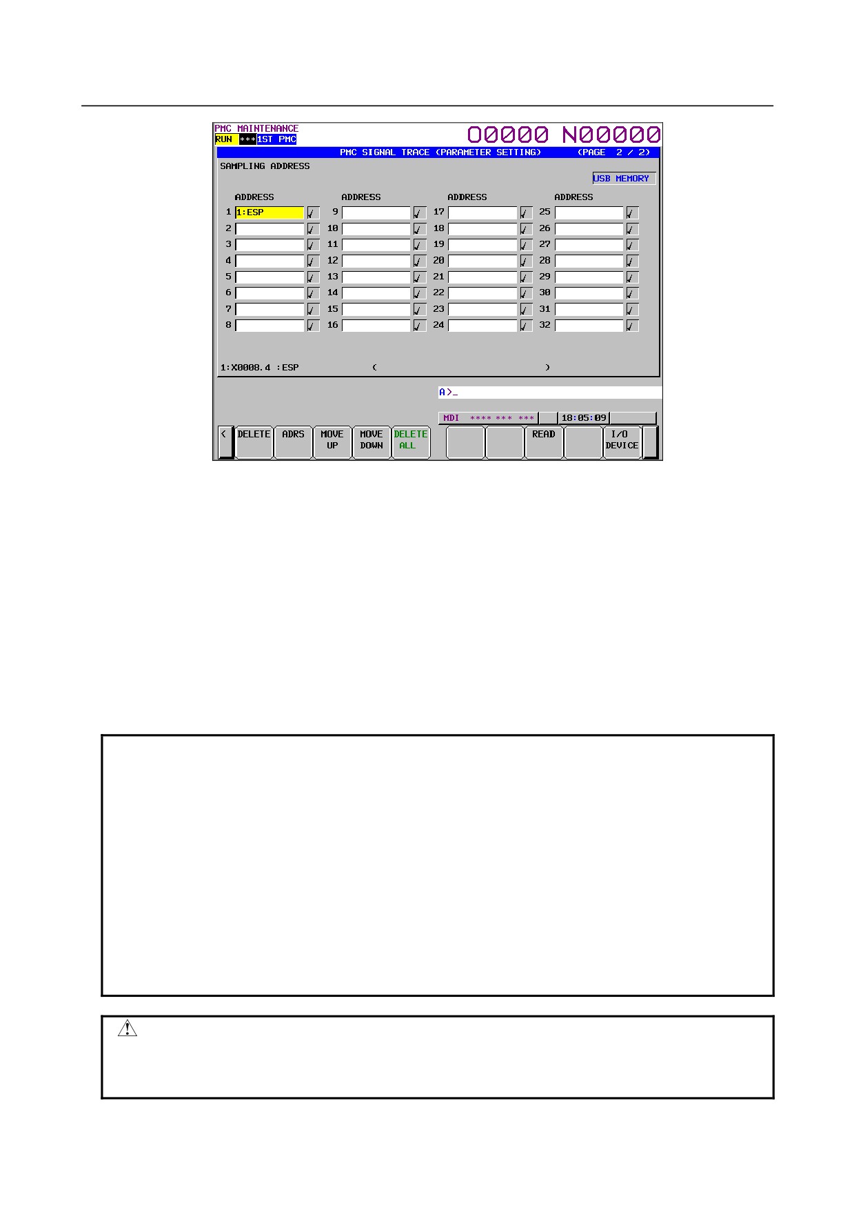
Fig. 6.5.10 (b) Trace parameter setting screen (second page)
(a) Setting addresses
In case of inputting discrete bit addresses, any bit address can be inputted.
Moreover, when you input byte address, all bits of the address (bits 0 to 7) are set automatically.
Maximum 32 points of signal address can be inputted.
With the multi-PMC system, an address can be set for a desired PMC by specifying its PMC
number.
Example: 2:R9200.1 + Input key
A setting can be made by entering "PMC number" + ":" + "address" as indicated above.
In case of DCSPMC, enter "S:"+"address".
When no PMC number is specified, the specification of the currently selected PMC is assumed. In
this case, "PMC number" + ":" is automatically prefixed to a specified address.
When only one PMC is used as in the standard PMC system, no PMC number needs to be specified.
NOTE
1 For the PMC numbers, see Section 7.2.
2 If there is not “:” key on your keyboard, use “;” or “/” instead.
3 Increasing the number of the signal address changes the capacity of
"SAMPLING/ TIME" or "SAMPLING/ FRAME" in page 1. If the capacity is
changed, the following warning message is displayed. (The "n" on the message
means the maximum value that is able to input.)
a) In case of "TIME CYCLE" mode
"SAMPLING TIME IS REDUCED TO n SEC."
b) In case of "SIGNAL TRANSITION" mode
"SAMPLING FRAME IS REDUCED TO n."
4 The signal trace for the DCSPMC is executed in the same timing as signals of
1st to 5th paths PMC.
CAUTION
The signal trace of the DCSPMC does not synchronize with the ladder execution
period of the DCSPMC. Therefore, when plural signals are traced, the timing of
tracing may not be accurate.
- 375 -
6.INTERFACE BETWEEN CNC AND PMC
B-64485EN/01
b) Soft keys
Soft keys on the setting screen of sampling address are as follows
•
DELETE
: Clears the value of the edit box on the cursor.
•
SYMBOL/ADDRESS : Changes the address display to the symbol display. However, display
of the address that is not defined the symbol does not change. This
soft key also changes to "ADDRESS". The following soft keys are
displayed.
•
MOVE UP
: Exchanges the signal indicated the cursor for the signal above one line.
•
MOVE DOWN : Exchanges the signal indicated the cursor for the signal below one line.
•
DELETE ALL
: Clears all of the value of the edit box.
•
READ
: Reads the trace setting files.
•
I/O DEVICE
: Selects input device of the trace setting file and output device of the trace
result data. Pressing the soft-key switches
“memory card” or
“USB
memory” alternately.
c) Trigger setting
When "SIGNAL TRANSITION" is set on "TRACE MODE" and "ANY CHANGE" is set on
"SAMPLING CONDITION", it can be set whether to use the setting address as the signals that
should trigger the sampling in the setting signals. As for the signal address where the trigger was set,
"9 " is displayed right. Soft keys on the Trigger setting screen are as follows:
•
TRGON: Sets the Trigger on.
•
TRGOFF:Sets the Trigger off.
The default setting is trigger on for all signals.
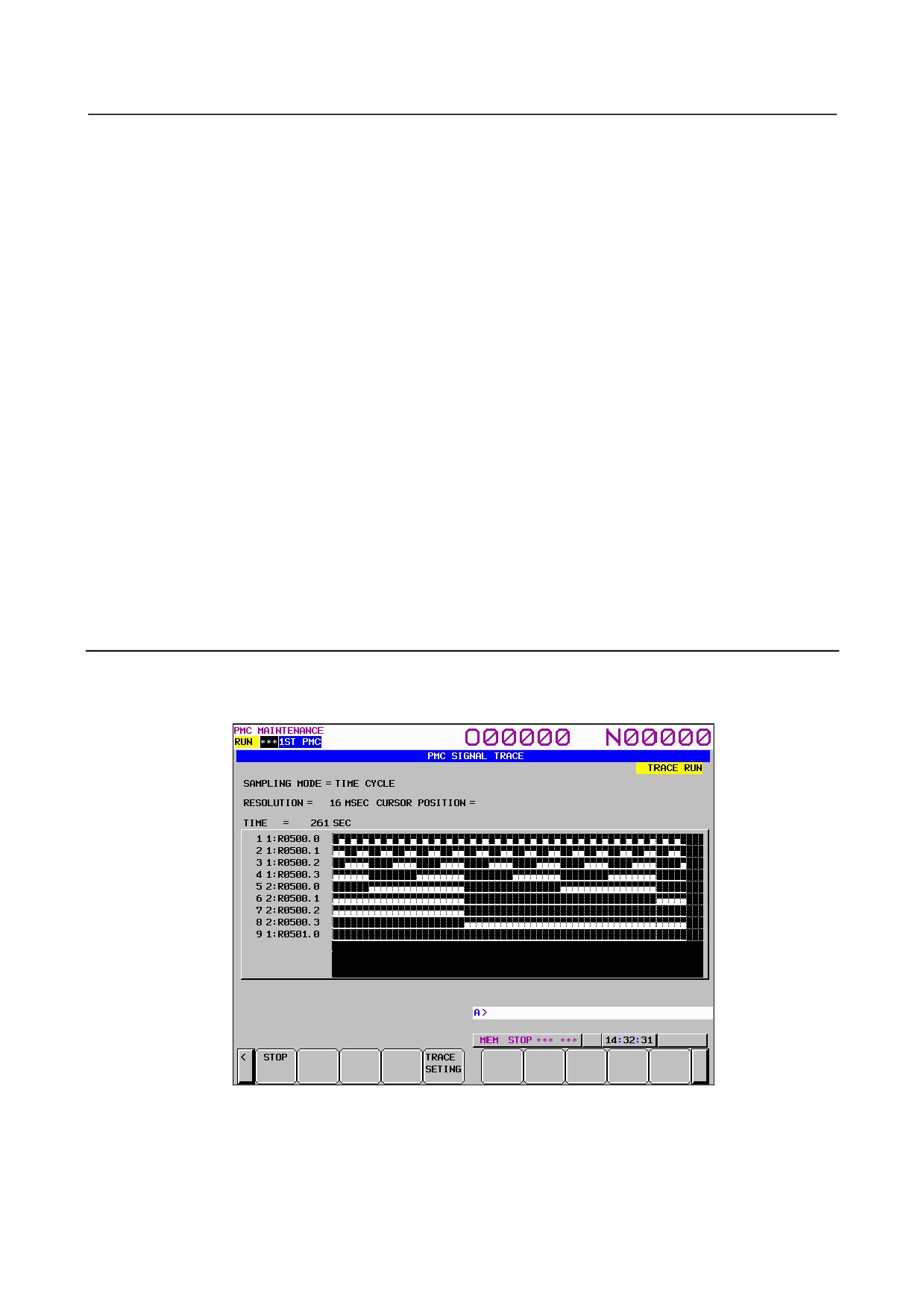
6.5.11 Execution of Trace
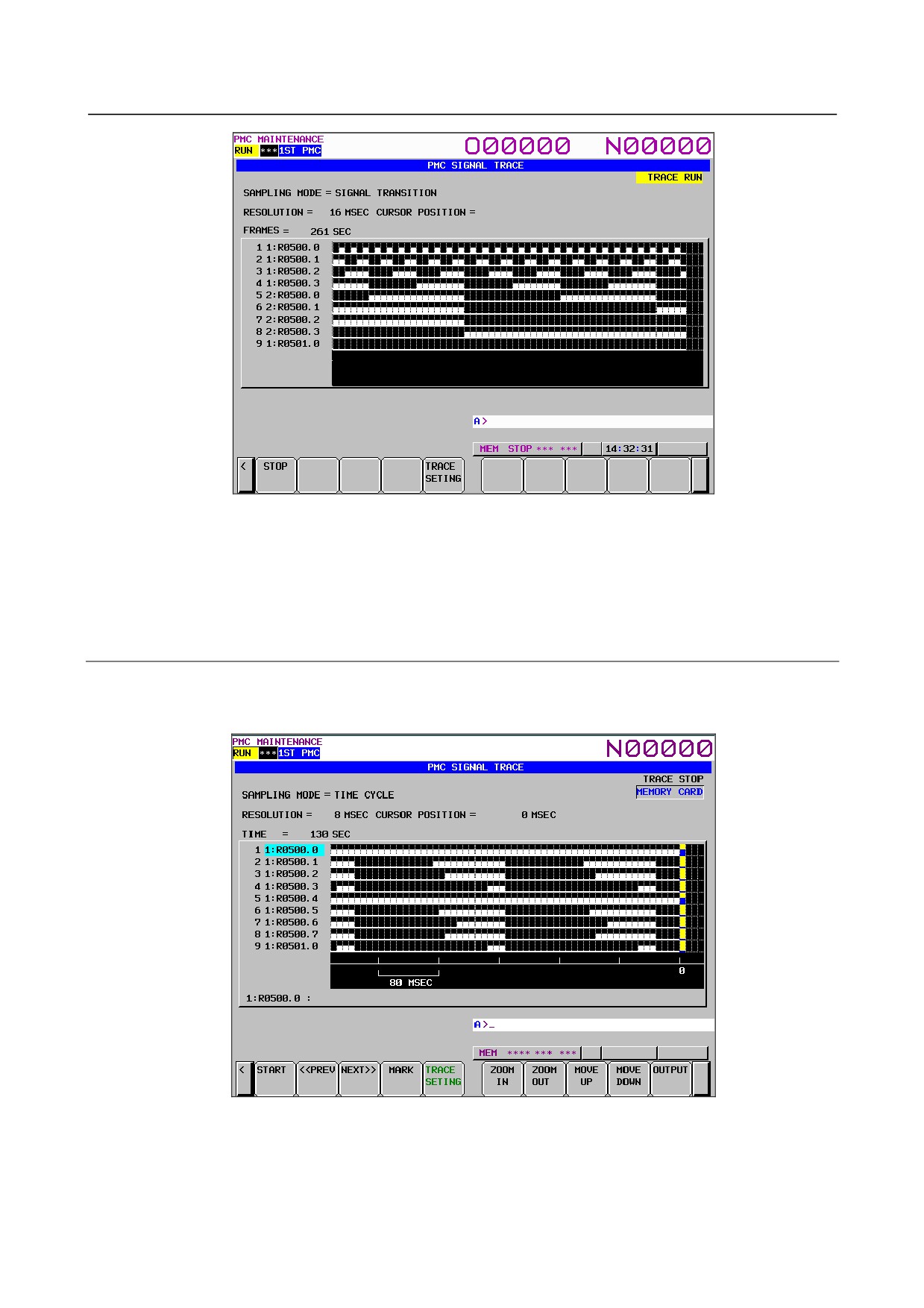
After the trace parameters are set, a trace operation can be started by pressing the soft key [(OPRT)] and
the soft key [RUN] on the SIGNAL TRACE screen. The following is the screen examples of the trace
execution by "TIME CYCLE" mode and "SIGNAL TRANSITION" mode.
Fig. 6.5.11 (a) Trace execution screen (TIME CYCLE mode)
- 376 -
B-64485EN/01
6.INTERFACE BETWEEN CNC AND PMC
Fig. 6.5.11 (b) ) Trace execution screen (SIGNAL TRANSITION mode)
The result of trace is immediately displayed during execution of the trace.
When the stop conditions that is set in parameter setting screen is satisfied the execution is finished.
Pushing soft key [STOP] aborts the execution. In "SIGNAL TRANSITION" mode, graphic display is not
refreshed until any signal for sampling trigger changes.
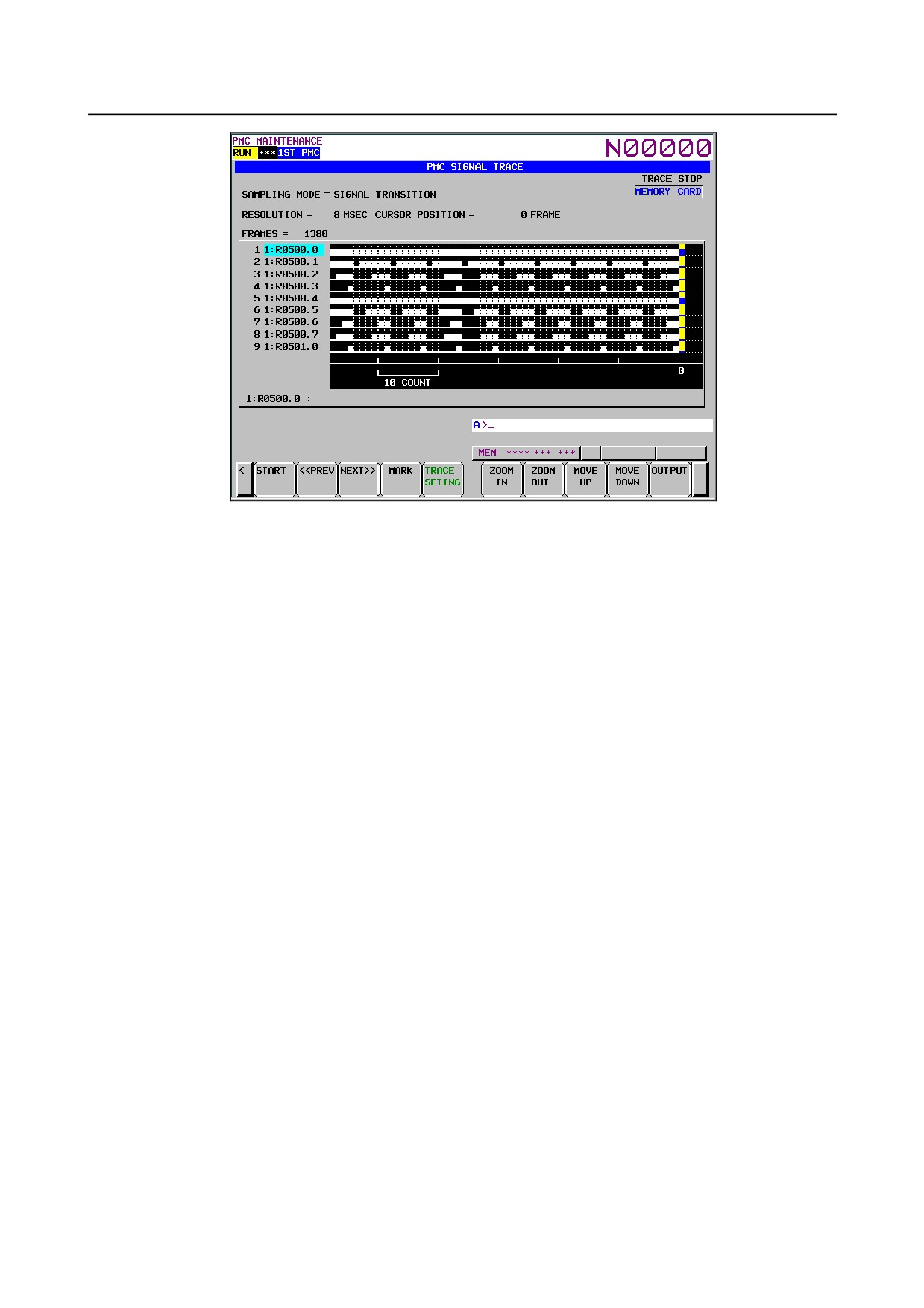
6.5.11.1 Operation after execution of trace
When the execution is finished, the result of trace is displayed. The Fig. 6.5.11.1 (a) and Fig. 6.5.11.1 (b)
are the screen examples of trace by "TIME CYCLE" and "SIGNAL TRANSITION" mode.
Fig. 6.5.11.1 (a) Trace result screen (TIME CYCLE mode)
- 377 -
6.INTERFACE BETWEEN CNC AND PMC
B-64485EN/01
Fig. 6.5.11.1 (b) Trace result screen (SIGNAL TRANSITION mode)
The cursor indicating current position is initially displayed on the original point (0 point). The position of
the cursor is displayed in "CURSOR POSITION" in the upper of the screen. The cursor can move
horizontally with the <←> or <→> key. After the execution, following operation is enabled.
a) Scroll of screen
•
Cursor up/down key and Page up/down key
Enables the vertical scroll for the specified signal
•
Cursor right/left key, soft key [NEXT>>] and soft key [<< PREV]
Enables the horizontal scroll of the graph.
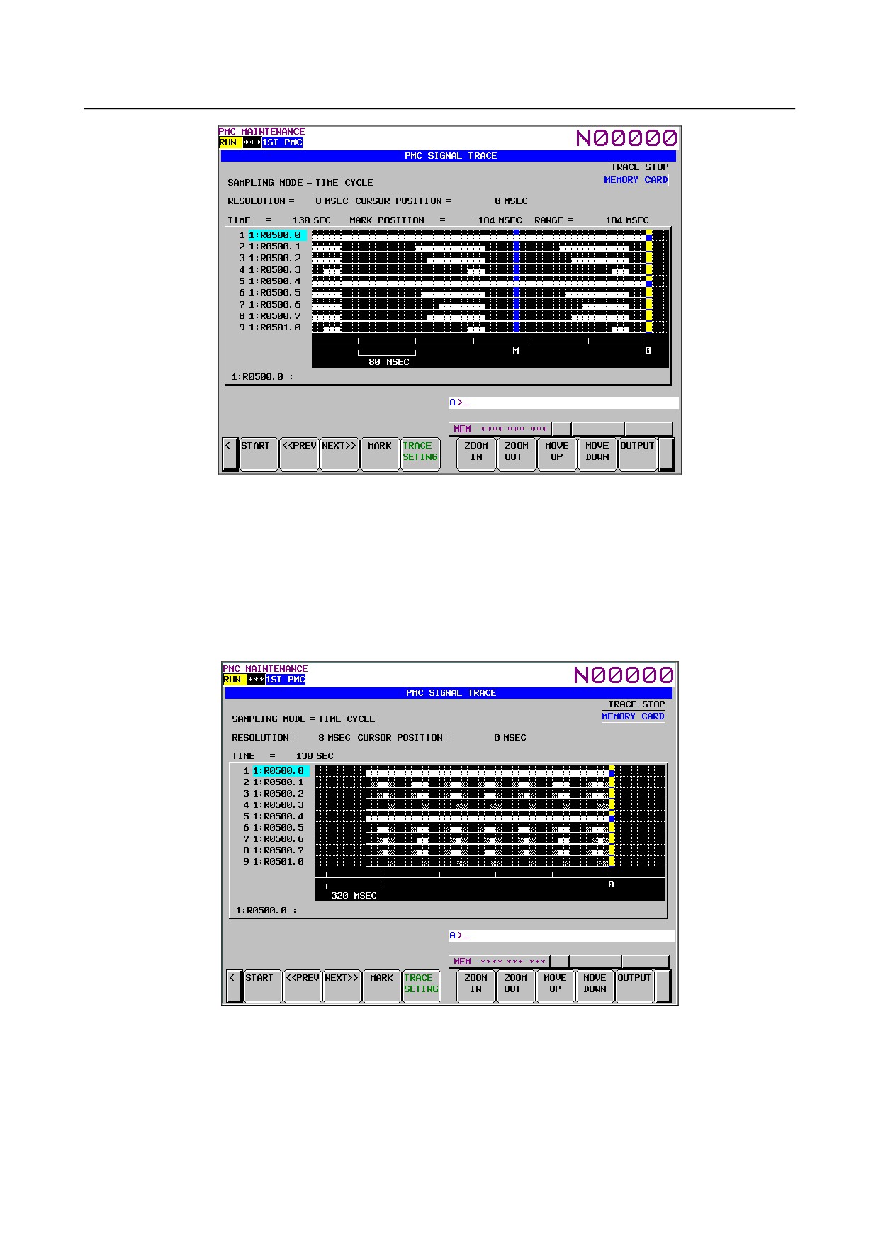
b) Automatic calculation of the selected range
Pushing soft key [MARK] marks the current position and displays the mark cursor.
If the mark cursor duplicates with the current position cursor, the current position cursor has priority
of display. The "MARK POSITION" that shows the position of the mark cursor and "RANGE" that
shows the range between the mark cursor and the current position cursor are displayed in the upper
of screen.
Moving the current position cursor changes these values. Pushing soft key [MARK] again releases
the select range mode.
- 378 -
B-64485EN/01
6.INTERFACE BETWEEN CNC AND PMC
Fig. 6.5.11.1 (c) Trace result screen (Mark cursor display)
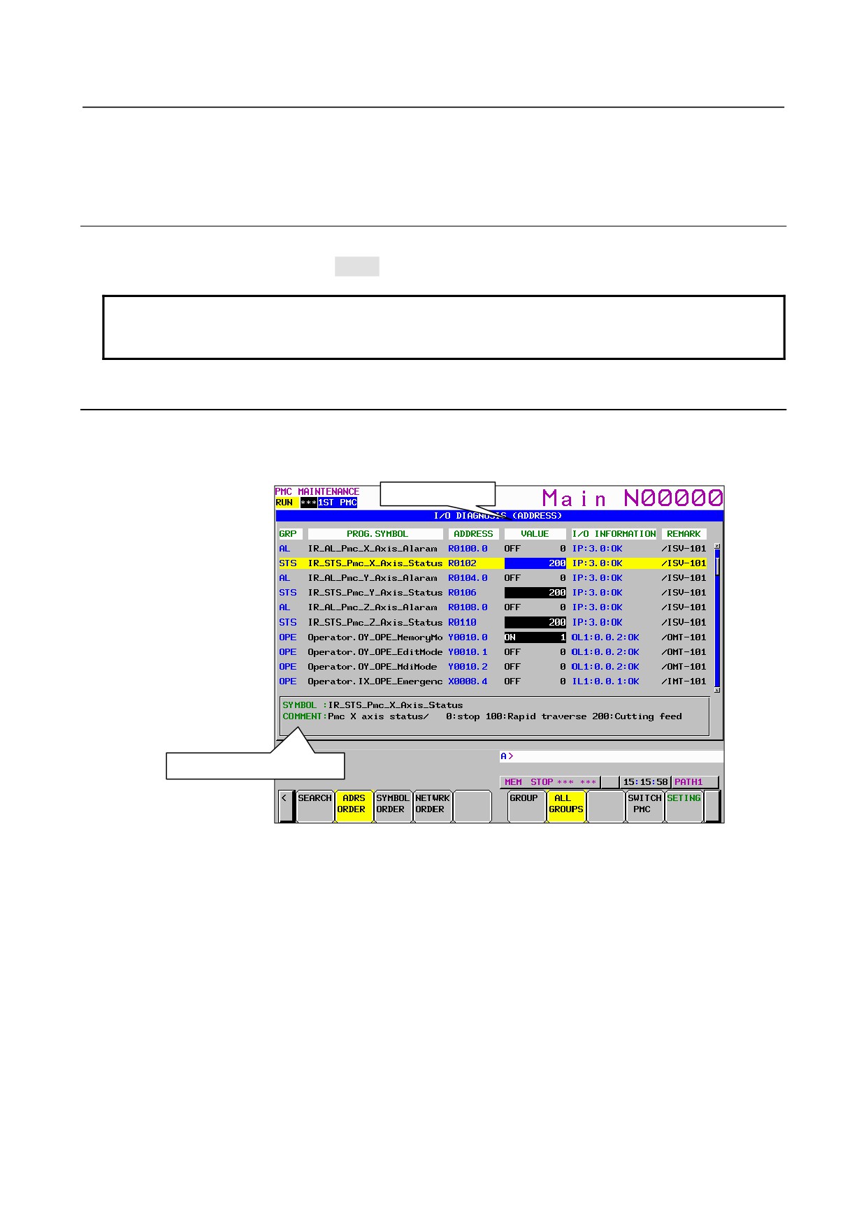
c) Zoom in/Zoom out of waveform
Pushing soft key [ZOOM IN] magnifies the display of chart. Pushing soft key [ZOOM OUT]
reduces the display of chart. Pushing these soft keys also change the scale value of the graduation on
the graph. When trace is just finished, the default zooming level was the most magnified level. In
[ZOOM OUT] mode, "X" is displayed as following screen example when the transitions of signal
cannot be expressed accurately enough. The limitation of [ZOOM OUT] displays all of result of the
trace in one page.
Fig. 6.5.11.1 (d) Trace result screen (Zoom out display)
d) Exchange of sampling signal
Pushing soft key [MOVE UP] exchanges the signal indicated by the signal cursor for the signal one
line above. Pushing soft key [MOVE DOWN] exchanges the signal indicated by the signal cursor
for the signal one line below. The result of the operation is cancelled by the execution of trace or
putting the power off. When you would like to preserve the order of displayed signals against the
executing or powering off, please change the order on "SAMPLING ADDRESS" screen.
- 379 -
6.INTERFACE BETWEEN CNC AND PMC
B-64485EN/01
e) Output of the trace result data
Pressing the [OUTPUT] soft key outputs the trace result data to “memory card” or “USB memory”.
6.5.11.2 Automatic start of trace setting
Trace execution is automatically started after power-on by setting a PMC setting data.
• TRACE START = MANUAL/AUTO
NOTE
For details of the method of setting PMC setting data, see PMC
PROGRAMMING MANUAL (B-64513EN).
6.5.12 MONITORING I/O DIAGNOSIS ([I/O DGN] SCREEN)
In I/O Diagnosis screen, you can check the status of each I/O variable. You can also check the
configuration of I/O devices and the communication status with them.
Listing order
Additional information
Fig. 6.5.12 (a) I/O diagnosis screen
GRP (GROUP)
To include a specific string which means a kind of signals in a part of symbol string, these signals on I/O
diagnosis screen are classified and you can easy to understand the status of signals.
The group names of the I/O variables are displayed, which are extracted (Max. 4 chars) out of their
symbol names as configured in “GROUP FORMAT” in the setting screen.
The groups to be displayed can be specified by soft key.
[ALL GROUPS] All groups are displayed.
[GROUP]
The group entered by key or the group under the cursor is selected to be displayed.
PROG.SYMBOL (SYMBOL)
The symbol names of the I/O variables are displayed.
ADDRESS
The actual locations of I/O variables are displayed.
- 380 -
B-64485EN/01
6.INTERFACE BETWEEN CNC AND PMC
VALUE
The current values of I/O variables are displayed as signed decimal, according to the data type of them
(i.e. BOOL, BYTE, WORD, and DWORD).
I/O INFORMATION
The information related to I/O network is displayed in the display format below:
<I/O type><Network type> : <Network address> : <status>
I/O type:
Module type
Shown as
Input module
I
Output module
O
Other
Network type:
Network type
Shown as
PROFIBUS
P
I/O LINK
Ln (n: channel number)
I/O LINK i
Ln (n: channel number)
Network address:
Network type
Network address notation
PROFIBUS
<Slave #>.<Slot #>
I/O LINK
<Group #>.<Base #>.<Slot #>
I/O LINK i
<Group #>.<Slot #>
- 381 -
6.INTERFACE BETWEEN CNC AND PMC
B-64485EN/01
NOTE
This screen shows the I/O information according to the network setting that
became effective at the time of the last power-on.
The notes for each network device are as follows:
PROFIBUS
1. If you have changed some of the profibus parameters, you have to cycle the
power once to make the changes take effect.
I/O LINK
1. Only the I/O Link assignments, which are made effective by the setting of
“Machine Signal Interface” in Configuration Parameter menu and the setting
of
“Communication method of I/O Link” in NC Parameter and the setting of
“Selectable I/O Link Assignment Function”, are displayed.
2. If you have changed the following parameters, you have to cycle the power
once to make them take effect:
• “I/O Link assignment data”
• “Machine signal interface” in PMC configuration parameter
• Parameter of “Selectable I/O Link assignment function”
3. If you have stored new sequence program to PMC, its I/O Link assignment
data will not take effect until you write it into Flash-ROM and cycle the power
once.
I/O Link i
1. Only the I/O Link i assignments, which are made effective by the setting of
“Communication method of I/O Link” in NC Parameter and the setting of
“Selectable I/O Link i Assignment Function”, are displayed.
2. If you have changed the following parameters, you have to cycle the power
once to make them take effect:
• “I/O Link i assignment data”
• “Communication method of I/O Link” in NC Parameter
• Parameter of “Selectable I/O Link i assignment function”
3. If you have stored new I/O configuration data to PMC, its I/O Link i
assignment data will not take effect until you write it into Flash-ROM and
cycle the power once.
Status: the status of communication
“OK” or “NG” is displayed.
REMARK
The remarks up to 8 characters extracted from comment data are displayed. To specify the remark at this
field, set “100” to the attribute value of the comment, which you want to show in this field, on FANUC
LADDER-III,
Additional information window
In this window, symbol and comment of the I/O variable under the cursor are displayed. When language
dependent comment attributes are specified, corresponding comment is displayed according to the current
language setting of the CNC.
In FANUC LADDER-III, the attribute value of comment should be set to 0 to 18 to display language
dependent comment
- 382 -
B-64485EN/01
6.INTERFACE BETWEEN CNC AND PMC
Attribute value: 0 to 18
0: English
10: Portuguese
1: Japanese
11: Polish
2: German
12: Hungarian
3: French
13: Swedish
4: Chinese (Traditional)
14: Czech
5: Italian
15: Chinese (Simplified)
6: Korean
16: Russian
7: Spanish
17: Turkish
8: Dutch
18: Bulgarian
9: Danish
NOTE
In case of the extended symbol and comment, the comments on the screen will
be switched dynamically to new language when the language setting of CNC
changes.
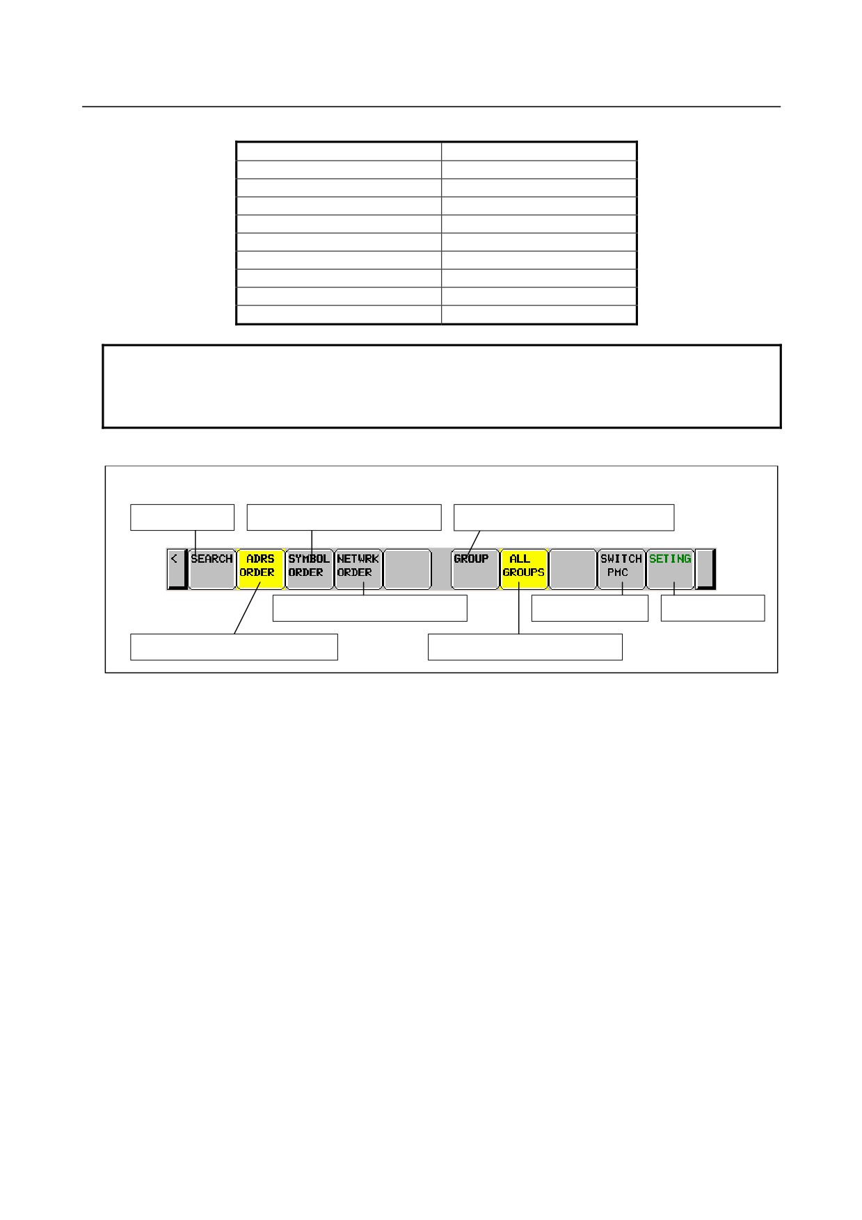
Soft key
Softkeys on the I/O Diagnosis screen
Search for data
Switch to the address order display
Switch to the specified group display
Switch to the address order display
Switch PMC path
Screen settings
Switch to the address order display
Switch to the all group display
- 383 -
6.INTERFACE BETWEEN CNC AND PMC
B-64485EN/01
6.6
LADDER DIAGRAM MONITOR AND EDITOR SCREENS
([PMC LADDER])
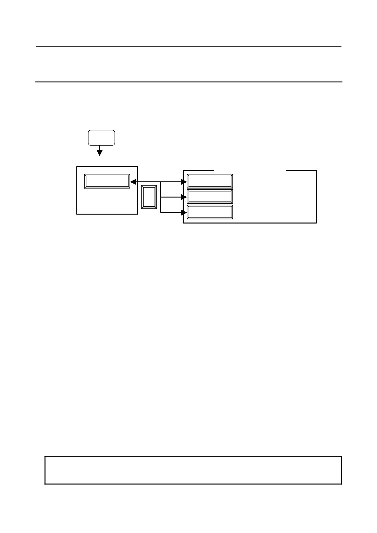
The PMC LADDER menu contains the screens related to PMC Ladder diagrams, such as the program list
screen and the LADDER DIAGRAM MONITOR/EDITOR screens.
You can switch to the PMC LADDER menu by operating on the "SYSTEM" key and then the soft key
[PMC LADDER].
SYSTEM
PMC main menu
PMC LADDER menu
PMC LADDER
LIST
Program list screen
LADDER DIAGRAM
<
LADDER
MONITOR/EDITOR screen
Duplicate coil check screen
DUP. CHECK
Fig. 6.6 (a) PMC LADDER menu
Clicking the soft key [LADDER] causes the sequence program to be dynamically displayed, allowing you
to monitor operation. The editor screen allows you to make changes to relay and functional instructions in
the sequence program to change the operation of the sequence program.
The ladder diagram display/editor functions consist of the following screens:
(1) LADDER DIAGRAM MONITOR screen
Displays ladder diagrams to monitor the current states of relays, coils, and so on.
(2) COLLECTIVE MONITOR screen
Displays only a selected ladder net to monitor the current states of relays, coils, and so on.
(3) LADDER DIAGRAM EDITOR screen
Allows you to edit a ladder diagram in units of nets.
(4) NET EDITOR screen
Allows you to edit a single net in a ladder diagram.
(5) PROGRAM LIST VIEWER screen
Allows you to select the subprogram to be displayed on the LADDER DIAGRAM MONITOR
screen.
(6) PROGRAM LIST EDITOR screen
Allows you to edit a ladder program in units of subprograms. Also allows you to select the
subprogram to be edited on the LADDER DIAGRAM EDITOR screen.
The following screens can be called from the LADDER DIAGRAM EDITOR screen:
(7) FUNCTIONAL INSTRUCTION DATA TABLE VIEWER screen
Allows you to view the contents of the data table for a data table attached functional instruction.
(8) FUNCTIONAL INSTRUCTION DATA TABLE EDITOR screen
Allows you to edit the contents of the data table for a data table attached functional instruction.
(9) SUBPROGRAM LIST VIEWER screen
Displays the list of the called subprogram and the subprogram switching history.
NOTE
You can protect these screens by using the programmer protection function. For
details, see PMC PROGRAMMING MANUAL (B-64513EN).
- 384 -
B-64485EN/01
6.INTERFACE BETWEEN CNC AND PMC
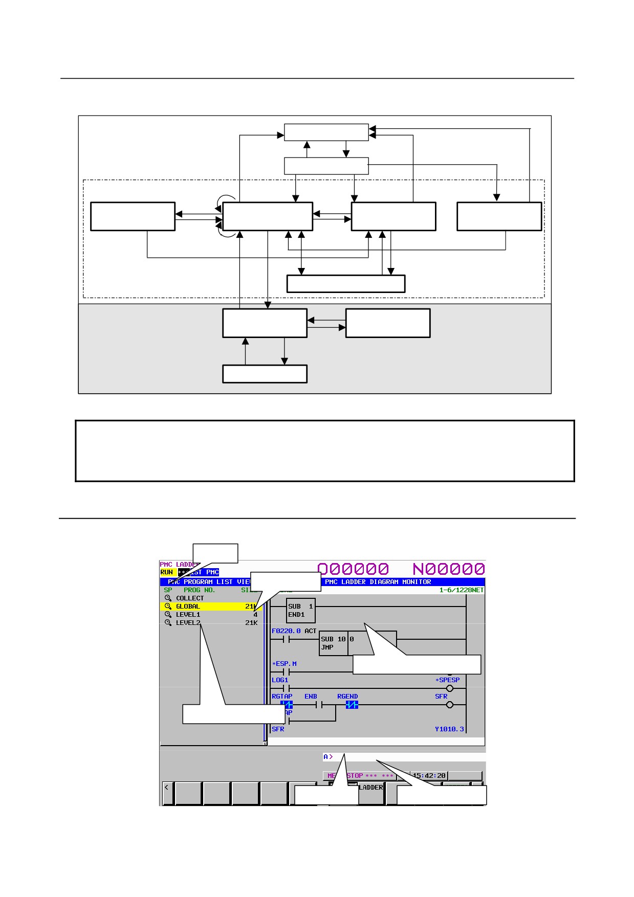
You can move among screens as shown in the Fig. 6.6 (b).
Display Function
PMC main menu
(Monitor)
[<]
[PMC LADDER]
PMC LADDER menu
[<]
[<]
[DUP. CHECK]
[<]
[BACK]
[LADDER]
[LIST]
[SPLIST]
[ZOOM]
SUBPROGRAM LIST
LADDER DIAGRAM
PROGRAM LIST
Duplicate coil check
VIEWER screen
MONITOR screen
VIEWER screen
screen
[LADDER]
[LIST]
[ZOOM]
[BACK]
[LIST]
[ZOOM]
[JUMP]
[BACK]
[LIST]
[ZOOM]
[EXIT EDIT]
[SWITCH]
[EDIT]
COLLECTIVE MONITOR screen
Edit Function
[ZOOM]
LADDER DIAGRAM
PROGRAM LIST
EDITOR screen
EDITOR screen
[LIST]
[EXIT]
[CREATE NET]
[ZOOM]
NET EDITOR screen
Fig. 6.6 (b) Transition among screens
NOTE
The [EDIT] soft key on the LADDER DIAGRAM MONITOR screen is displayed
and becomes available if the programmer protection function enables to edit
ladder program. For details, see PMC PROGRAMMING MANUAL (B-64513EN).
6.6.1
Displaying a Program List ([LIST] Screen)
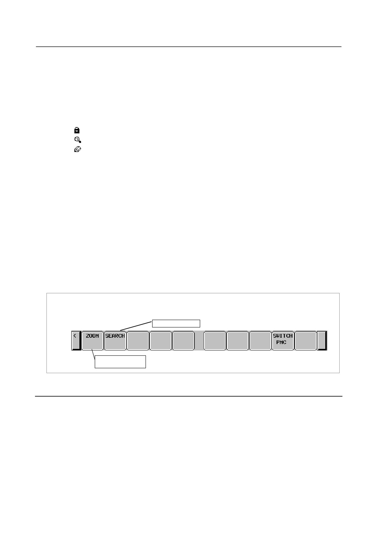
The PROGRAM LIST VIEWER screen shows program information such as the program size.
SP area
Size area
Ladder preview display area
Program number area
Key input line
Message display line
Fig. 6.6.1 (a) Program list viewer screen
- 385 -
6.INTERFACE BETWEEN CNC AND PMC
B-64485EN/01
(1)
Screen structures
(a) A program list is displayed on the left side of the screen; on the right side, the ladder diagram
of the program currently indicated by the cursor on the program list is displayed.
(b) In the message line, error messages or inquiry messages will be displayed depending on the
situation.
(c) The program list displays up to 18 programs at a time in the list display area.
(2)
Area of program list
(a) In the "SP area", the protect information for subprograms is displayed, so are their program
types.
(Key):Ladder program, cannot be viewed, cannot be edited
(Magnifying glass): Ladder program, can be viewed, cannot be edited
(Pencil): Ladder program, can be viewed, can be edited
(b) Program name is displayed in the "PROG NO." field for each program.
There are three kinds of program names.
COLLECT:
It means the collective program.
GLOBAL:
It means the whole program.
LEVELn (n = 1, 2, 3):
It means the Ladder level 1, 2 and 3.
Pm (m = subprogram number):
It means subprogram.
By changing the "ADDRESS NOTATION" item on the LADDER DIAGRAM MONITOR
Setting screen to "SYMBOL", you can display symbols.
(c) The program size is displayed in the "SIZE" field for each program.
If the program size is not over 1024 byte, the unit is shown in byte.
If it is over 1024 byte, the unit is shown in kilo (1024) byte with "K".
Ex.) The case that program size is not over 1024 byte.
1023 bytes:
"1023" is shown.
Ex.) The case that program size is over 1024 byte.
20000 bytes:
"19K" is shown.
(Sizes are rounded off to whole numbers before being displayed.)
Soft key of PROGRAM LIST VIEWER screen
Search for program
Display the contents
of program
6.6.2
Monitoring Ladder Diagrams ([LADDER] Screen)
LADDER DIAGRAM MONITOR screen shows the on/off status of contacts and coils, and the contents
of address specified for parameter of functional instructions.
From the PMC LADDER menu, you can switch to the LADDER DIAGRAM MONITOR screen by using
the soft key [LADDER]. You can use following operation at this screen, including "Forced I/O function
(Forcing mode)", by which you can force the relay or the address parameters of functional instructions to
a new status or value.
• Switch subprogram to show
[LIST]
• Search for address or others
[SEARCH MENU]
• Show data table of functional instructions
[DATA TABLE]
• Go to COLLECTIVE MONITOR Screen
[SWITCH]
• Forced I/O function (Forcing mode)
"number" + INPUT key
- 386 -
B-64485EN/01
6.INTERFACE BETWEEN CNC AND PMC
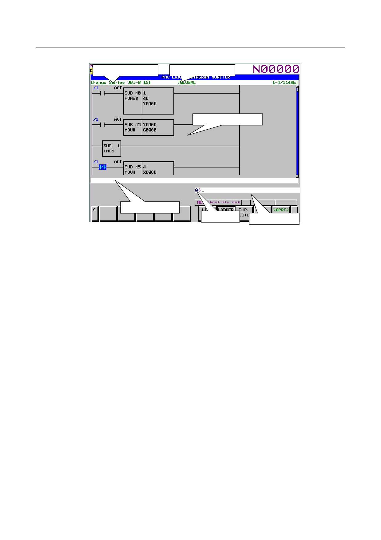
Title information (REMARKS)
Current subprogram
Area for LADDER Diagram
Additional information line
Key input line
Message line
Fig. 6.6.2 (a) Ladder diagram monitor screen
(1)
Screen structures
(a) Title information (REMARKS) of the LADDER Program, the current subprogram, and the
current position information of the Diagram displayed in this screen, are displayed above the
LADDER Diagram.
When you select a subprogram to be displayed, range for search function is indicated at right of
the top line as "LOCAL" or "GLOBAL". In case of "LOCAL", the range for search function is
restricted within the current subprogram. In case of "GLOBAL", on the other hand, search
function searches whole of LADDER program, and switch current subprogram automatically
according to the result of searching.
(b) In the additional information line near the bottom of the screen, the following information of
the address under the cursor when the cursor is shown.
• Net number of the net with the cursor
• Address and its symbol and comment information
• Current value
(c) In the message line, error messages or inquiry messages will be displayed depending on the
situation.
(d) In the area for LADDER diagrams, 8 × 8, 8 × 6, 8 × 4, 7 × 8, 7 × 6, and 7 × 4 relays can be
displayed (horizontally and vertically). For details, see PMC PROGRAMMING MANUAL
(B-64513EN).
(e) The gage indicating the current display position in relation to the whole Ladder program is
displayed at the right end of the screen.
(2)
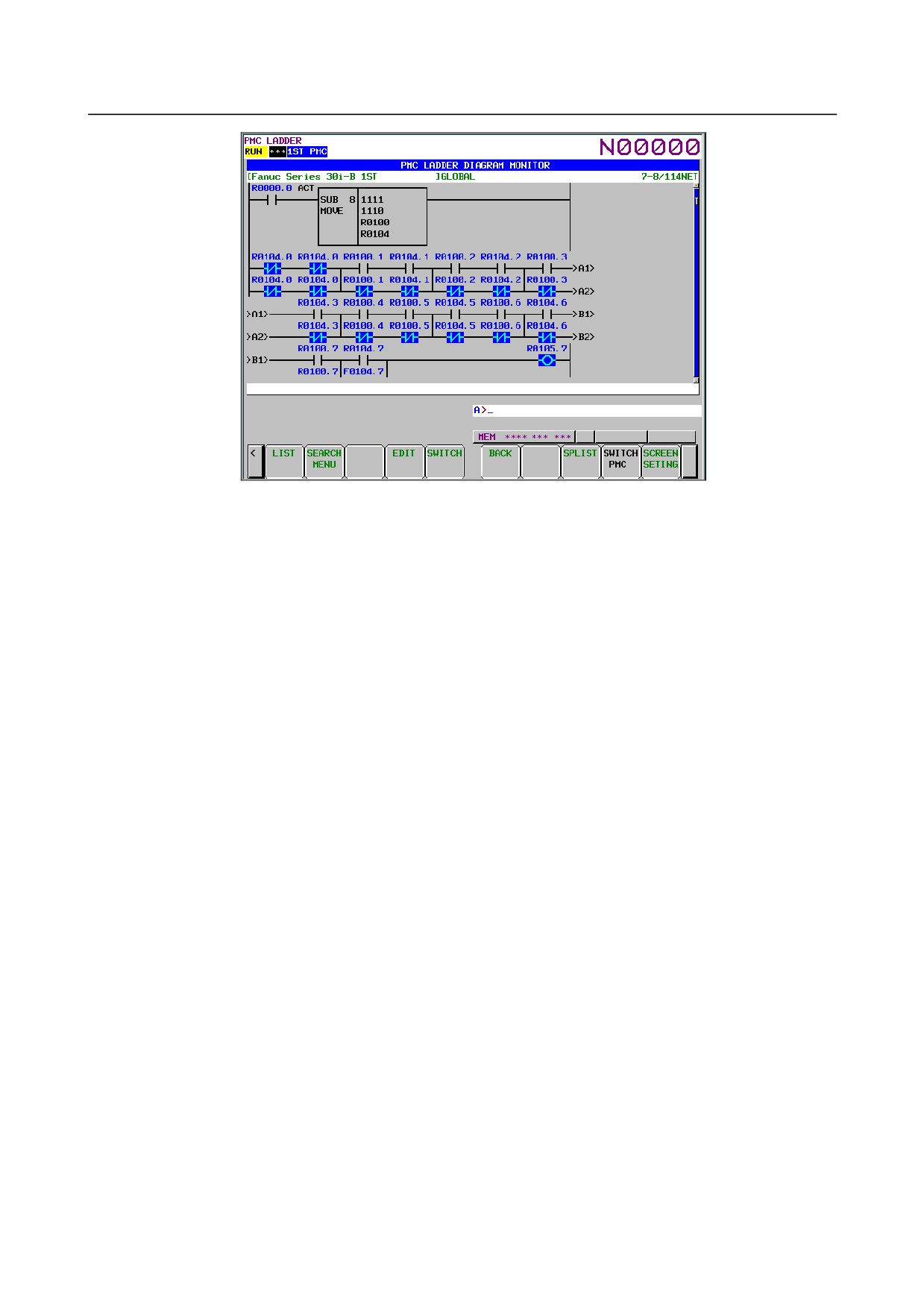
LADDER diagram
(a) Nets wider than the screen width are displayed as "Continuous Net" using continuous marks
(">A1>"). Same continuous marks mean they are connected with each other.
- 387 -
6.INTERFACE BETWEEN CNC AND PMC
B-64485EN/01
Fig. 6.6.2 (b) Ladder diagram monitor screen
(3) Monitor
(a) Contacts and coils are displayed in different colors according to the status of the signal. The
status of power flow is not displayed.
(b) Usually, the parameters of functional instructions are monitored and displayed. You can
suppress the monitor and display by an appropriate setting. For details, see PMC
PROGRAMMING MANUAL (B-64513EN).
(4) Displaying Symbols and Comments
(a) Usually, addresses are displayed above contacts and coils. For an address with a symbol
assigned, you can change the setting so that the symbol is displayed instead of the address. You
can add colors to addresses. For details, see Subsection “Setting the Display Format of the
LADDER DIAGRAM MONITOR Screen” in the PMC PROGRAMMING MANUAL
(B-64513EN).
(b) If the address of a contact has a comment attached, the comment is displayed below the contact.
You can change its display mode by changing the setting. You can add colors to comments. For
details, see Subsection “Setting the Display Format of the LADDER DIAGRAM MONITOR
Screen” in the PMC PROGRAMMING MANUAL (B-64513EN).
(c) If the address used with coil has a comment string assigned, the comment strings will be
displayed at the right margin beside the coil. You can use this margin area to display an
additional relay instead of the comment string by setting: at this setting, one more relay can be
displayed in each diagram line. You can add colors to comments. For details, see Subsection
“Setting the Display Format of the LADDER DIAGRAM MONITOR Screen” in the PMC
PROGRAMMING MANUAL (B-64513EN).
- 388 -
B-64485EN/01
6.INTERFACE BETWEEN CNC AND PMC
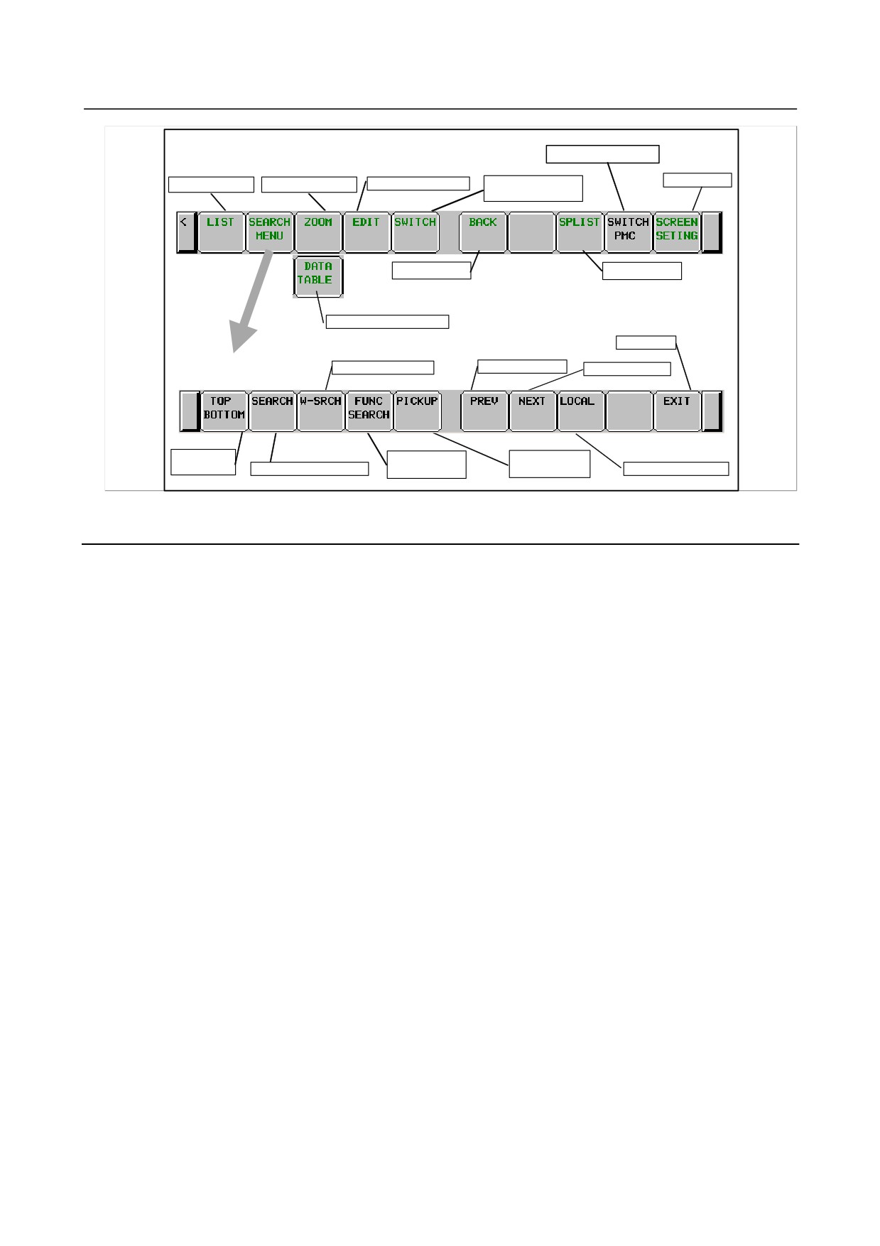
Main soft keys of LADDER Diagram Monitor screen
Switch PMC paths
LADDER Diagram Editor
Switch to COLLECTIVE
Screen Settings
Program List
Display Subprogram
MONITOR screen
Back previous
Subprogram List
Display Data Table
Exit
Search soft keys
Search Write Coil
Search previous
Search next
Jump to
Search Functional
Pick up a Ladder
Top/Bottom
Search Address or Net
Instruction
Diagram net
Switch range
6.6.3
Editing Ladder Programs
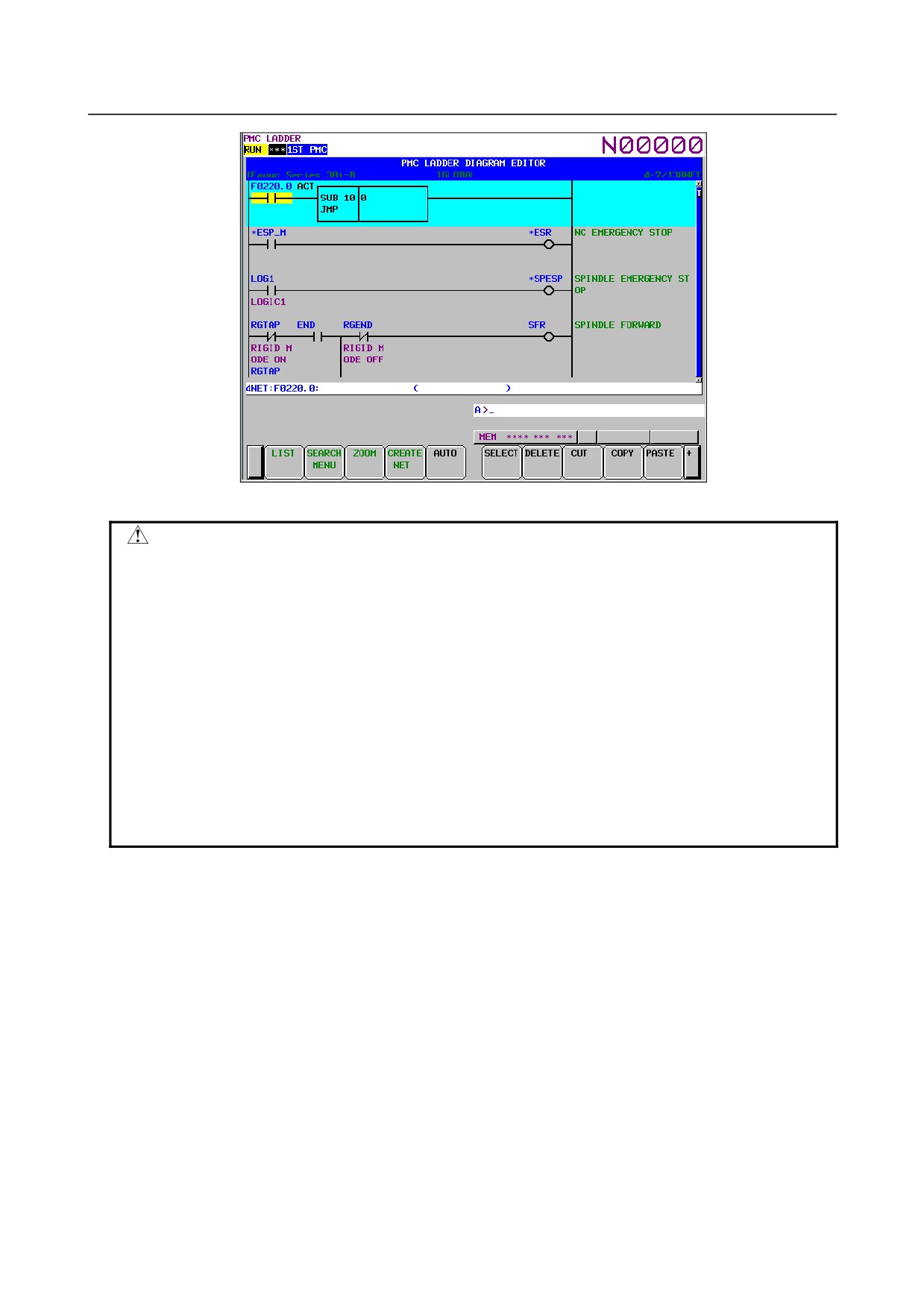
At LADDER DIAGRAM EDITOR screen you can edit LADDER program to change its behavior.
To switch LADDER DIAGRAM EDITOR screen, press soft key [EDIT] at LADDER DIAGRAM
MONITOR screen.
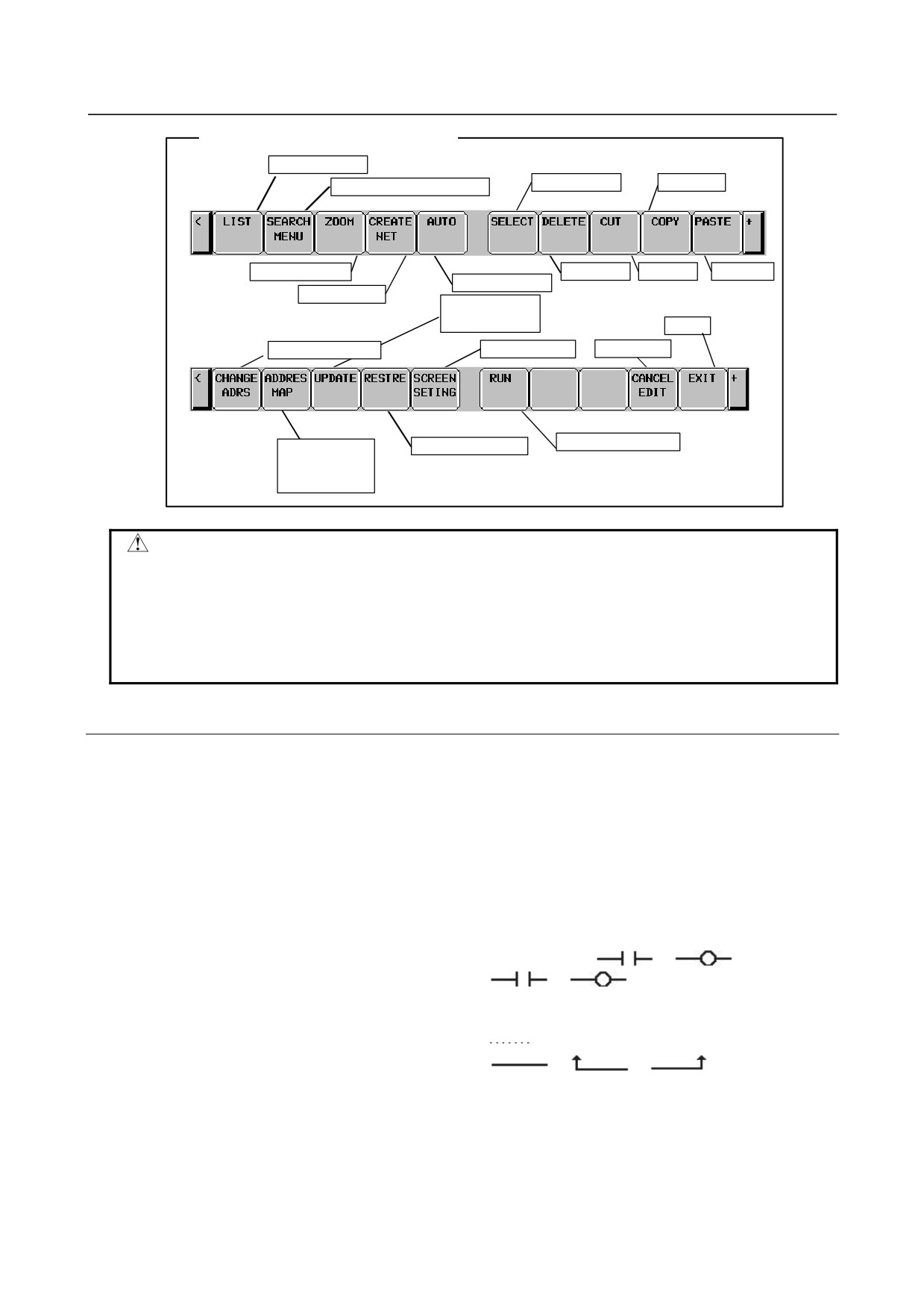
Following operations are available at LADDER DIAGRAM EDITOR screen.
•
Delete by net
[DELETE]
•
Move by net
[CUT] & [PASTE]
•
Copy by net
[COPY] & [PASTE]
•
Change address of contacts and coils
"bit address" + INPUT key
•
Change parameters of functional instructions
"number" or "byte address" + INPUT key
•
Add new net
[CREATE NET]
•
Change construction of net
[ZOOM]
•
Make changes effective
[UPDATE]
•
Abandon changes
[RESTRE]
•
Cancel edit
[CANCEL EDIT]
- 389 -
6.INTERFACE BETWEEN CNC AND PMC
B-64485EN/01
Fig. 6.6.3 (a) Ladder diagram editor screen
CAUTION
1 You can edit ladder programs regardless of whether they are active or not. To
execute a ladder program with the results of editing being reflected, you must
update the ladder program. To do this, click the soft key [UPDATE], or update the
program when exiting from the LADDER DIAGRAM EDITOR screen. For details
of the method of protecting editing, see
“PMC PROGRAMMING MANUAL
(B-64513EN).”
2 After you have edited a sequence program, the results of editing will be lost if the
power is turned off without first writing the edited sequence program to flash
ROM.
Write the sequence program to flash ROM on the I/O screen. If you set "WRITE
TO F-ROM(EDIT)" to "YES" on the general functions' setting parameter screen, a
confirmation message will be displayed, prompting you to ask whether to write a
sequence program to flash ROM after the end of editing. For details of this
setting, see “PMC PROGRAMMING MANUAL (B-64513EN).”
(1) Screen structures
(a) It is basically same with LADDER DIAGRAM MONITOR screen, except that no monitor
displays of relays and parameters of functional instructions are displayed.
(b) At right side of LADDER Diagram area, a position bar is always displayed, which indicates
screen position within current subprogram: in LADDER DIAGRAM MONITOR screen, this
position bar is exclusively displayed with comments of write coil. Sometimes, this position bar
hides a part of write coil comments.
(2) LADDER Diagram
(a) Style of LADDER Diagram is basically same with LADDER DIAGRAM MONITOR screen,
except that functional instructions are drawn always in "COMPACT" format that has no
monitor displays.
(b) Cursor is shown always. And the net, which will be an object of following editing operations, is
emphasized in screen.
- 390 -
B-64485EN/01
6.INTERFACE BETWEEN CNC AND PMC
Soft keys of LADDER Diagram Editor screen
Program List
Select net
Copy net
Change to Search soft keys
Edit new net
Delete net
Cut net
Paste net
Automatic input
Add net
Make changes
effective
Exit
Change address
Setting screen
Cancel edit
Run/stop LADDER
Display address
Abandon changes
map display
screen
WARNING
You have to pay special attention to modify running LADDER program. If you
modify LADDER program in wrong way, or update LADDER program with the
machine in improper status, it may cause unexpected reaction of the machine.
You have to make it sure that modifications you make on LADDER program is
appropriate, machine is in proper status, and nobody is near the machine, when
you update LADDER program.
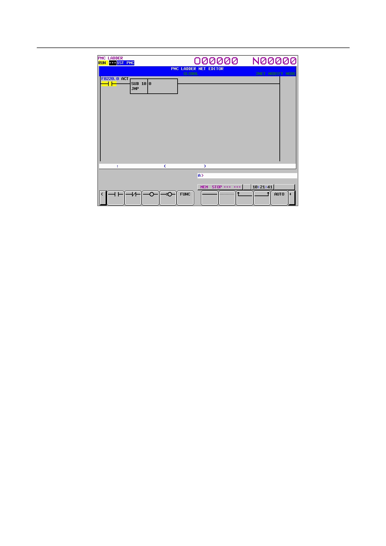
6.6.3.1 NET EDITOR screen
At NET EDITOR screen, you can create new net, and modify existing net.
• Changing existing nets
If you move a net with the soft key [ZOOM], you will enter a mode (Modify mode) in which you
can add changes to the net currently indicated by the cursor.
• Adding a new net
When soft key [CREATE NET] is used, this screen is in "New mode" to create new net from
nothing.
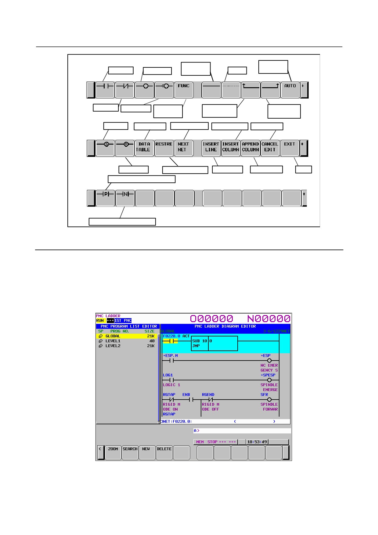
Following operations are available at this screen:
• Place new contacts and coils
"bit address" + [
], [
], etc.
• Change type of contacts and coils
[
], [
], etc.
• Place new functional instructions
[FUNC]
• Change type of functional instructions
[FUNC]
• Erase contacts, coils, and functional instructions
[
]
• Draw/erase connecting lines
[
], [
], [
]
• Edit data table of functional instructions
[DATA TABLE]
• Insert line/column
[INSERT LINE], [INSERT COLUMN], [APPEND COLUMN]
• Change address of contacts and coils
"bit address" + INPUT key
• Change parameters of functional instructions
"number" or "byte address" + INPUT key
• Abandon modifications
[CANCEL EDIT]
• Restore the net to the state it was before editing
[RESTRE]
- 391 -
6.INTERFACE BETWEEN CNC AND PMC
B-64485EN/01
Fig. 6.6.3.1 (a) Structure of the NET EDITOR screen
(1) Screen structures
(a) It is basically same with LADDER DIAGRAM EDITOR screen, except that only one net is in
this screen, and that position bar at right edge of screen does not appear at this screen.
(b) Current edit mode is indicated at right of the top line as "NEW MODE" or "MODFY MODE".
When soft key [ZOOM] at LADDER DIAGRAM EDITOR screen is used to reach NET
EDITOR screen, the screen is in Modify mode, and when soft key [CREATE NET] is used, it
is in New mode.
(c) Current net number is displayed at right of the top line. The net number is same with the net
number in previous LADDER DIAGRAM EDITOR screen.
(d) NET EDITOR screen expands image of net horizontally for a wider net according to its width,
while LADDER DIAGRAM MONITOR/EDITOR screen folds nets wider than screen width.
When net width is expanded over screen width, attempt to move cursor out of screen will scroll
net image to the direction.
The net of maximum size occupies area of 1024 elements, but actually available area may be
little less for internal use according to the internal condition: "element" means the space that is
occupied by single relay.
- 392 -
B-64485EN/01
6.INTERFACE BETWEEN CNC AND PMC
Soft keys of Net Editor screen
Automatic
Horizontal
A contact
input
Normal coil
connection
Delete
B contact
Inverted coil
Functional
Left vertical
Right vertical
instructions
connection
connection
Set coil
Data table
Edit next net
Insert column
Cancel edit
Reset coil
Abandon changes
Insert line
Add column
Exit
Positive transition contact
Negative transition contact
6.6.4
PROGRAM LIST EDITOR Screen
At PROGRAM LIST EDITOR screen you can create new program and delete a program in addition to
the function of PROGRAM LIST VIEWER screen. To reach this screen, press soft key [LIST] at
LADDER DIAGRAM EDITOR screen. Following operations are available at PROGRAM LIST
EDITOR screen. For more detail of these operations, see the descriptions of each key to operate.
• Create new program [NEW]
• Delete a program
[DELETE]
Fig. 6.6.4 PROGRAM LIST EDITOR screen
On the PROGRAM LIST EDITOR screen, a preview of the editor screen for the ladder program currently
positioned by the cursor on the program list is displayed on the right of the screen.
- 393 -
6.INTERFACE BETWEEN CNC AND PMC
B-64485EN/01
Soft keys of Program List Editor screen
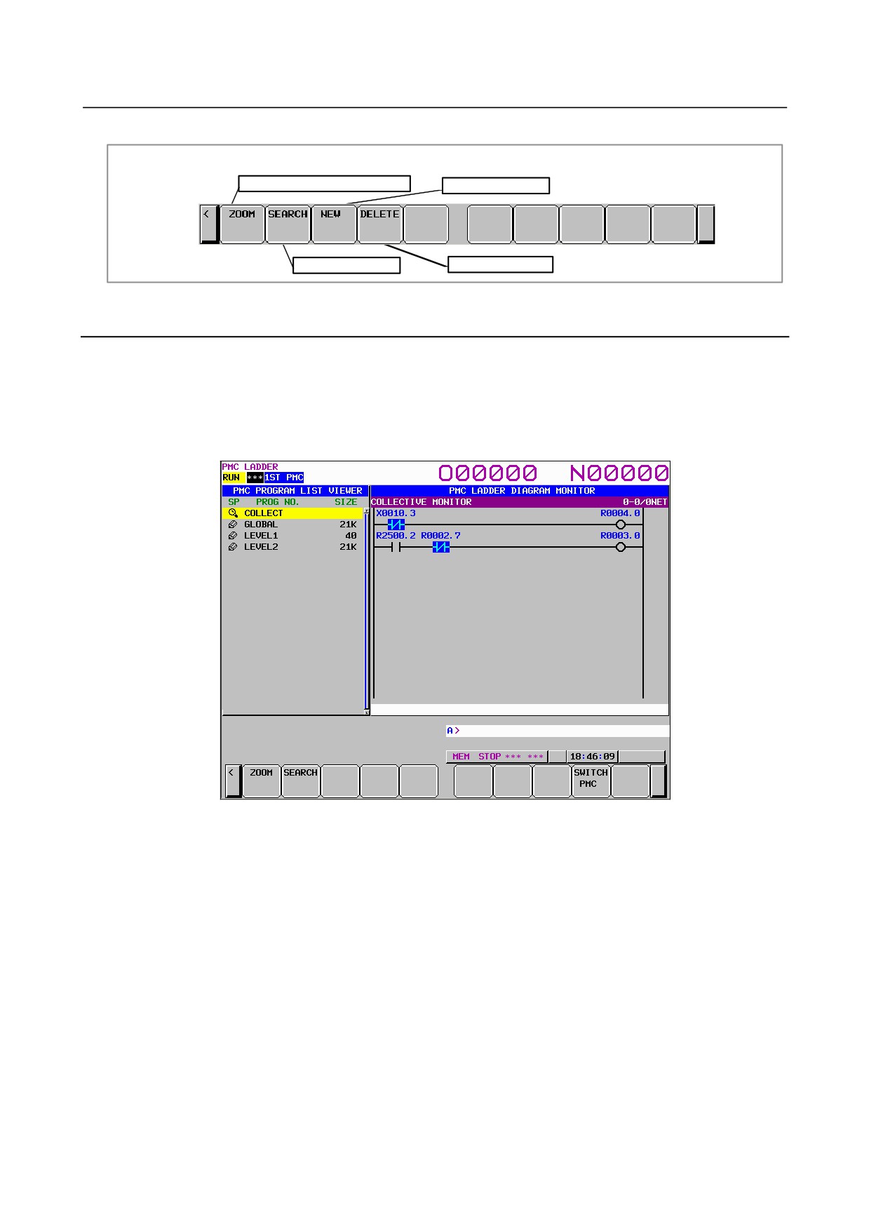
Display the contents of program
Add new program
Search for program
Delete a program
6.6.5
Collective Monitor Function
The COLLECTIVE MONITOR screen allows you to specify the ladder net containing the coils to be
monitored, so that you can monitor only the necessary ladder net.
The COLLECTIVE MONITOR screen can be called in either of the following ways:
(1) Calling from the PROGRAM LIST VIEWER screen
On the program list screen, move the cursor to the "COLLECT" program position, then click the soft
key [ZOOM].
Fig. 6.6.5 (a) PROGRAM LIST VIEWER screen
- 394 -
B-64485EN/01
6.INTERFACE BETWEEN CNC AND PMC
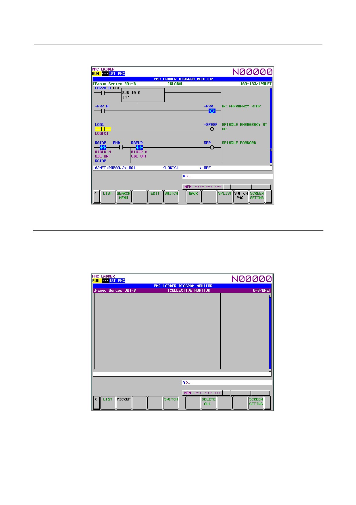
(2) Calling from the LADDER DIAGRAM MONITOR screen
On the LADDER DIAGRAM MONITOR screen, click the soft key [SWITCH].
Fig. 6.6.5 (b) LADDER DIAGRAM MONITOR screen
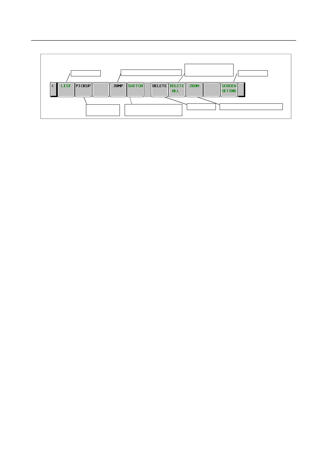
6.6.5.1 COLLECTIVE MONITOR function
The COLLECTIVE MONITOR screen is such as that shown Fig. 6.6.5.1 (a). At first, it does not display
any ladder diagram. Ladder nets will be added to this screen as they are selected with coil search and
pickup operations. Up to 128 nets can be added to the COLLECTIVE MONITOR screen. If an attempt is
made to add more, the most recently added 128 nets will be displayed.
Fig. 6.6.5.1 (a) COLLECTIVE MONITOR screen (initial screen)
- 395 -
6.INTERFACE BETWEEN CNC AND PMC
B-64485EN/01
(1) Operations using the soft keys
Soft keys of Collective Monitor screen
Initialization of
Program List
Jump to the ladder diagram net
COLLECTIVE MONITOR
Screen setting
Pick up a ladder
Switches to LADDER
Delete a net
Display a content of subprogram
diagram net
DIAGRAM MONITOR screen
Fig. 6.6.5.1 (b) Soft keys of COLLECTIVE MONITOR screen
(2)
Specifying the ladder diagram to monitor
The operation for picking up ladder nets which you want to monitor on COLLECTIVE MONITOR
screen is as follows.
(a) Specification of ladder nets on COLLECTIVE MONITOR screen
• Specify the address by key input
Pick up a ladder net by keying in the address used by a coil.
• Indication from a ladder net on the COLLECTIVE MONITOR screen
Indicate a relay on an already picked up ladder net, with the cursor, to pick up the net that
uses the relay address for the coil.
(b) Specifying a ladder net from the LADDER DIAGRAM MONITOR screen
Specify a net from the LADDER DIAGRAM MONITOR screen to pick it and load it into the
COLLECTIVE MONITOR screen.
(3)
Picking up a ladder net on the COLLECTIVE MONITOR screen
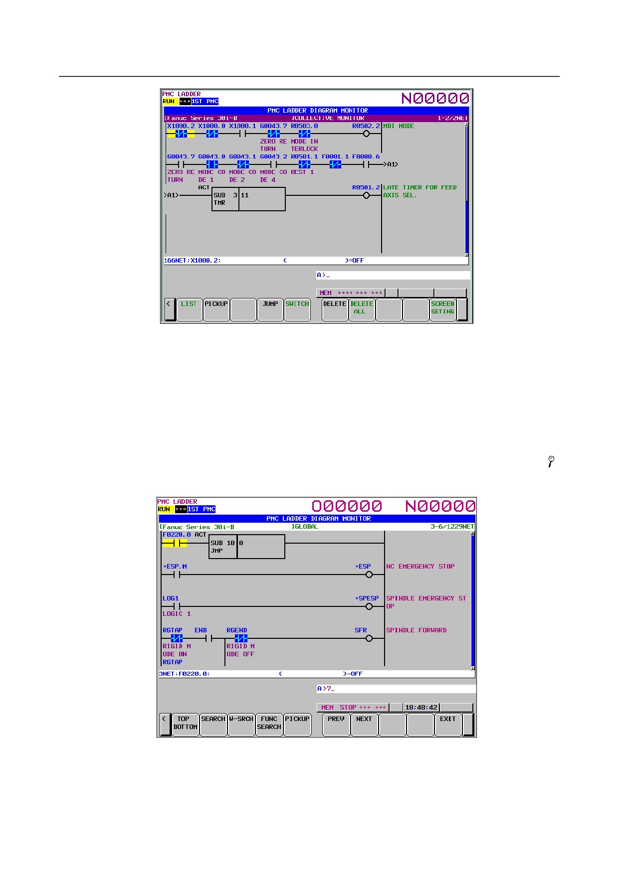
You can pick up a ladder net from the COLLECTIVE MONITOR screen. The procedure for picking
up a ladder net is as described below.
(a) Address specification
(i)
Enter the address to monitor (for example, R10.1).
(ii) Click the [PICKUP] soft key.
(iii) The net in which a coil uses the address specified in (i) will be picked up and loaded at the
beginning of the screen.
(b) Specification of an address from a ladder net on the screen
(i)
Move the cursor to a relay on the ladder net that uses the address you want to monitor.
(ii) Click the [PICKUP] soft key.
(iii) The net in which a coil uses the address specified in (i) will be picked up and loaded at the
beginning of the screen, and the cursor moves to the specified coil position.
- 396 -
B-64485EN/01
6.INTERFACE BETWEEN CNC AND PMC
Fig. 6.6.5.1 (c) COLLECTIVE MONITOR screen
(4) Picking up a ladder net from the LADDER DIAGRAM MONITOR screen
You can pick up a ladder net from the LADDER DIAGRAM MONITOR screen. The procedure for
picking up a ladder net is as described below.
(a) From the LADDER DIAGRAM MONITOR screen, click the soft key [SEARCH] to display
the soft keys for search.
(b) Move the cursor to the ladder net to pick up.
(c) Click the [PICKUP] soft key to pick up and load the net specified in (b) at the beginning of the
COLLECTIVE MONITOR screen.
(d) For the ladder net picked up and loaded into the COLLECTIVE MONITOR screen, the " "
mark is displayed at the left end of the net.
Fig. 6.6.5.1 (d) LADDER DIAGRAM MONITOR screen (search soft keys)
- 397 -
6.INTERFACE BETWEEN CNC AND PMC
B-64485EN/01
6.7
LIST OF ADDRESSES
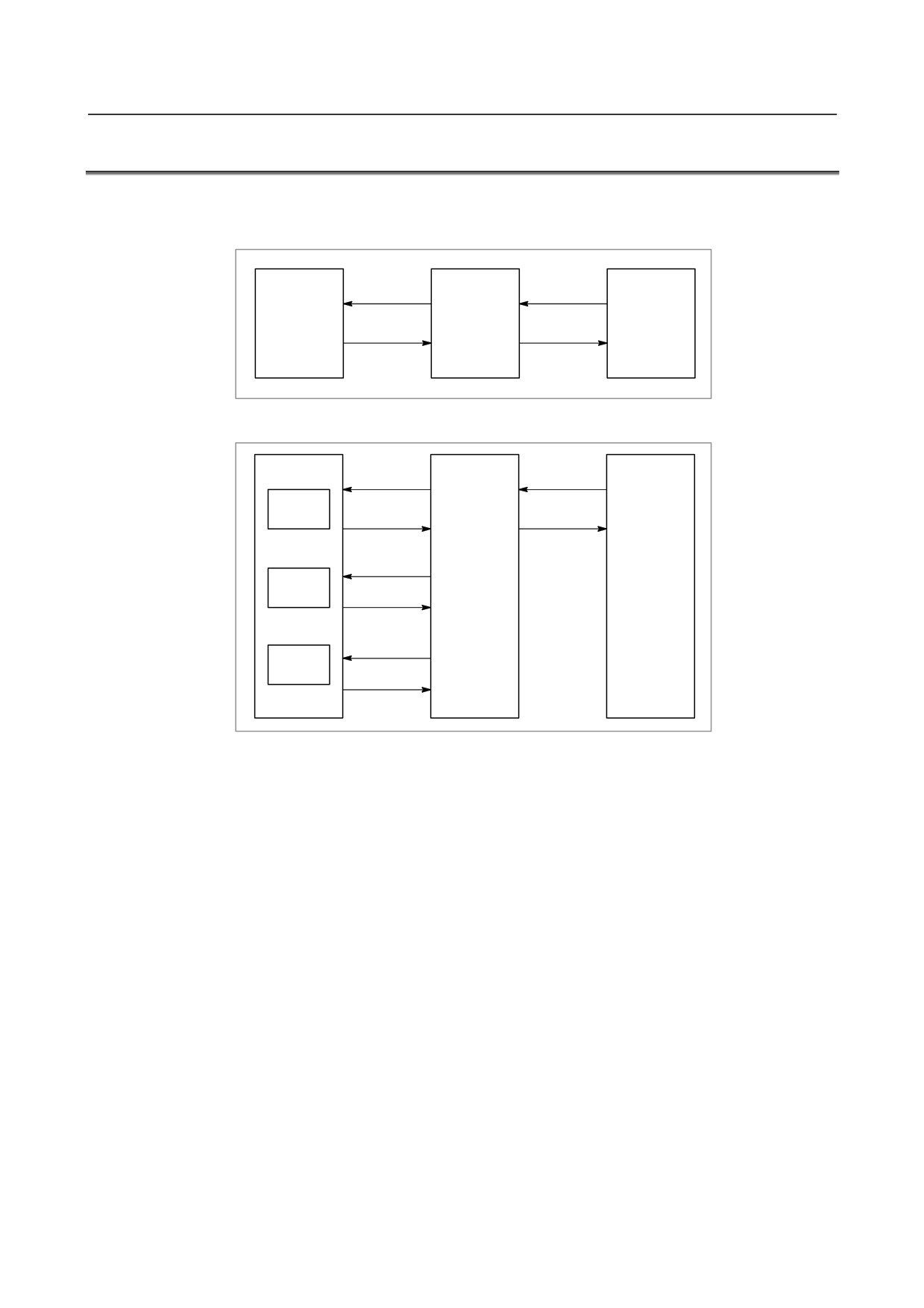
Interface addresses among CNC and PMC are as follows:
[Example of controlling one path using one PMC]
G0000~
X000~
Machine tool
CNC
PMC
F0000~
Y000~
[Example of controlling three path using one PMC]
CNC
G0000~
X000~
Path 1
F0000~
Y000~
PMC
Machine tool
G1000~
Path 2
F1000~
G2000~
Path 3
F2000~
- 398 -
B-64485EN/01
6.INTERFACE BETWEEN CNC AND PMC
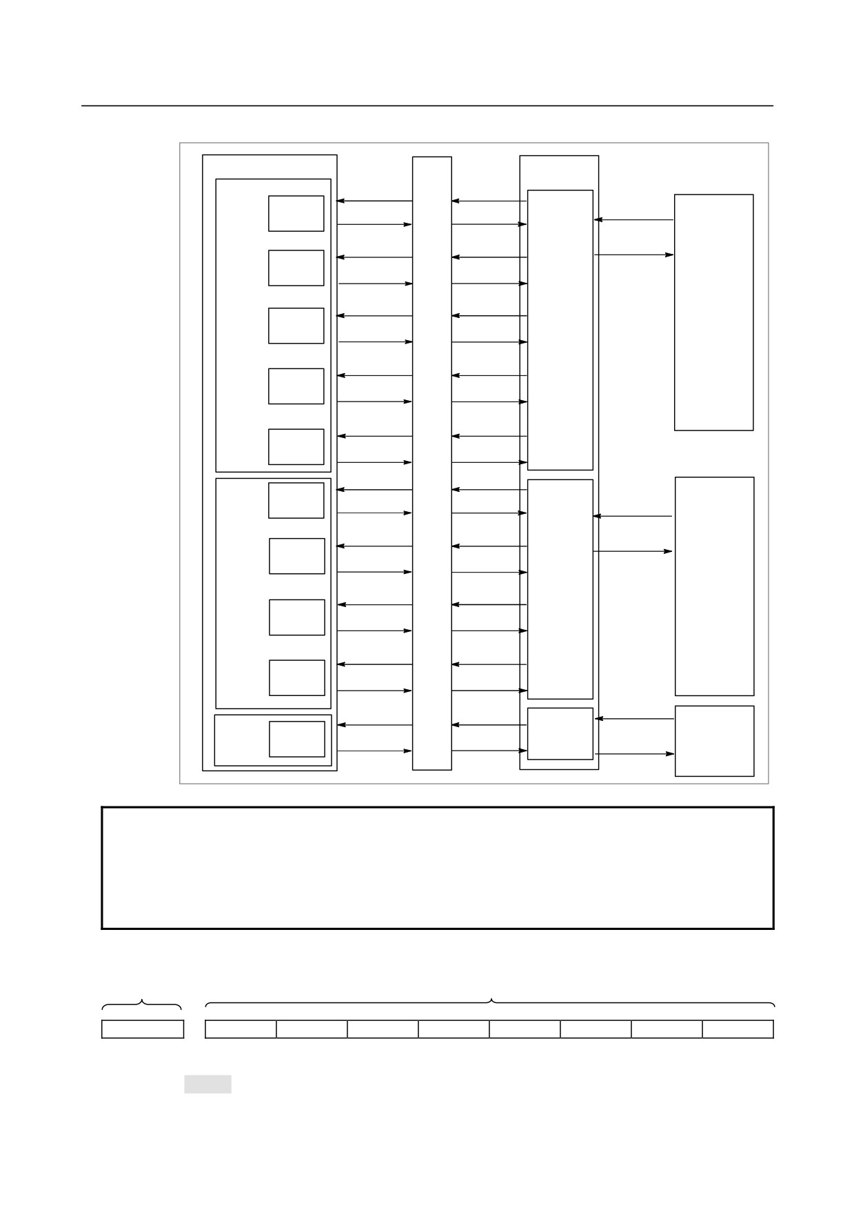
[Example of controlling multi-path CNC using PMC system]
CNC
Signal
PMC
I/F
G0000~
G0000~
X000~
Path 1
F0000~
F0000~
Y000~
I/O device
G1000~
G1000~
First
for first
PMC
Path 2
machine
F1000~
F1000~
G2000~
G2000~
First
machine
Path 3
F2000~
F2000~
group
G3000~
G3000~
Path 4
F3000~
F3000~
G4000~
G4000~
Path 5
F4000~
F4000~
G5000~
G0000~
Path 6
X000~
F5000~
F0000~
Second
I/O device
G6000~
G1000~
PMC
for second
Y000~
machine
Path 7
F6000~
F1000~
Second
machine
group
G7000~
G2000~
Path 8
F7000~
F2000~
G8000~
G3000~
Path 9
F8000~
F3000~
X000~
G9000~
G0000~
Third
Third
I/O device
machine
Path 10
PMC
for third
F9000~
F0000~
Y000~
group
machine
NOTE
Each PMC of a multi-path PMC system has an independent signal area. The F,
G, X, and Y signal addresses of each PMC begin with 0. On the other hand, the
F and G signal addresses from the viewpoint of the CNC are fixed for each path
number. Note that the F and G signal addresses used in programming of each
ladder are different from those from the viewpoint of the CNC.
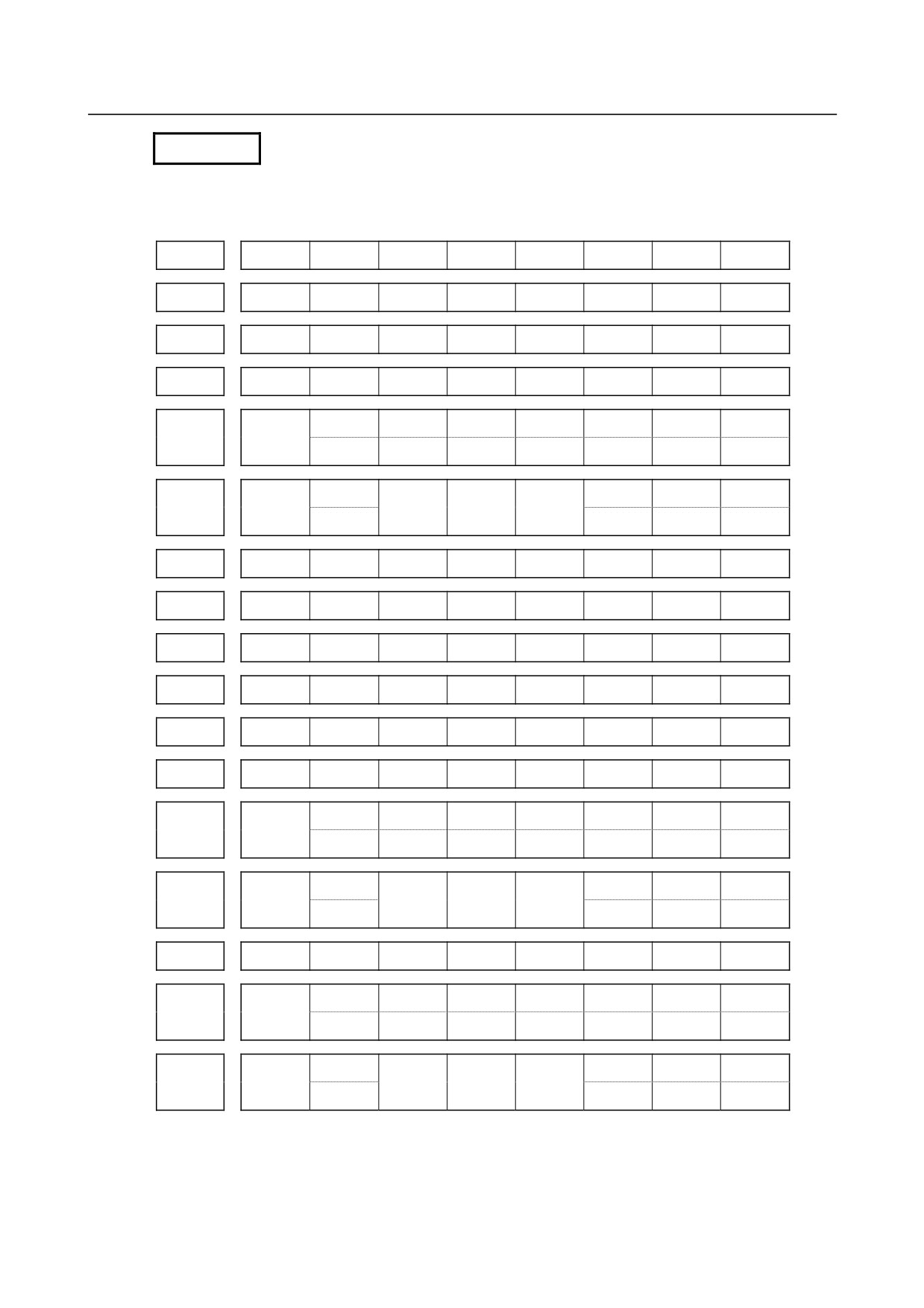
Expression of signals
Address
Symbol (#0 to #7 indicates bit position)
#7
#6
#5
#4
#3
#2
#1
#0
Fn000
OP
SA
STL
SPL
RWD
In an item where both lathe system and machining center system are described, some signals are covered
with shade (
) in the signal address figure as shown below. This means either lathe system or
machining center system does not have this signal. Upper part is for lathe system and lower part is for
machining center system.
- 399 -

6.INTERFACE BETWEEN CNC AND PMC
B-64485EN/01
#7
#6
#5
#4
#3
#2
#1
#0
T series
Gn053
*CDZ
ROVLP
UINT
TMRON
M series
[Example 1]
The figure above indicates ROVLP is provided only for the lathe system while the other signals for
both the lathe system and machining system.
#7
#6
#5
#4
#3
#2
#1
#0
T series
Gn040
OFN9
OFN8
OFN7
OFN6
M series
[Example 2]
Signals OFN6 to OFN9 are for machining center system only.
NOTE
1
In X addresses in the table, the emergency stop signal for each signal is
*ESP<X008.4>, *ESP<X008.0>, and *ESP<X008.1>, respectively.
2
For multi-path control, one of the following superscripts is attached to the top
right of a symbol depending on the signal type.
- Path type (for path 1 on PMC side) : #1
- Path type (for path 2 on PMC side) : #2
- Path type (for path 3 on PMC side) : #3
In addition, #1, #2 or #3 attached to a signal indicates the signal is provided only
for path 1, 2, or 3 on PMC side, respectively.
- Path type
: #P
- Controlled axis type
: #SV
- Spindle type
: #SP
In G and F addresses in the table, #P, #SV, or #SP attached to a signal
indicates the signal is provided for each path on CNC side, each control axis on
CNC side, or each spindle on CNC side, respectively.
- PMC axis control group type: #PX
#PX attached to a signal indicates the signal is provided for each PMC axis
control group.
3
For the signals, a single data number is assigned to 8 bits. Each bit has a
different meaning.
4
The letter "n" in each address representation indicates the address position used
in each path on the CNC side, as shown below.
1st path : n=0 (No. 0 to 999)
2nd path : n=1 (No. 1000 to 1999)
:
:
10th path : n=9 (No. 9000 to 9999)
5
For a signal of controlled axis type, when the number of axes exceeds eight for
each path, set parameter No. 3021 to address this situation.
6
For a signal of spindle type, when the number of axes exceeds four for each
path, set parameter No. 3022 to address this situation.
- 400 -
B-64485EN/01
6.INTERFACE BETWEEN CNC AND PMC
MT → CNC
Address
Bit number
7
6
5
4
3
2
1
0
X000
X001
X002
X003
ESKIP
-MIT2#1
+MIT2#1
-MIT1#1
+MIT1#1
+XAE2#1
+XAE1#1
X004
T series
SKIP #1
SKIP6 #1
SKIP5 #1
SKIP4 #1
SKIP3 #1
SKIP2 #1
SKIP8 #1
SKIP7 #1
ESKIP
+XAE3#1
+XAE2#1
+XAE1#1
X004
M series
SKIP #1
SKIP5 #1
SKIP4 #1
SKIP3 #1
SKIP6 #1
SKIP2 #1
SKIP8 #1
SKIP7 #1
X005
X006
X007
*DEC8#2
*DEC7#2
*DEC6#2
*DEC5#2
*DEC4#2
*DEC3#2
*DEC2#2
*DEC1#2
X008
*ESP
(*ESP)
(*ESP)
X009
*DEC8#1
*DEC7#1
*DEC6#1
*DEC5#1
*DEC4#1
*DEC3#1
*DEC2#1
*DEC1#1
X010
*DEC8#3
*DEC7#3
*DEC6#3
*DEC5#3
*DEC4#3
*DEC3#3
*DEC2#3
*DEC1#3
ESKIP#3
-MIT2#3
+MIT2#3
-MIT1#3
+MIT1#3
+XAE2#3
+XAE1#3
X011
T series
SKIP #3
SKIP6 #3
SKIP5 #3
SKIP4 #3
SKIP3 #3
SKIP2 #3
SKIP8 #3
SKIP7 #3
ESKIP#3
+XAE3#3
+XAE2#3
+XAE1#3
X011
M series
SKIP #3
SKIP5#3
SKIP4#3
SKIP3 #3
SKIP6 #3
SKIP2 #3
SKIP8 #3
SKIP7 #3
X012
ESKIP#2
-MIT2#2
+MIT2#2
-MIT1#2
+MIT1#2
+XAE3#2
+XAE2#2
X013
T series
SKIP #2
SKIP6 #2
SKIP5 #2
SKIP4 #2
SKIP3 #2
SKIP2 #2
SKIP8 #2
SKIP7 #2
ESKIP#2
+XAE3#2
+XAE2#2
+XAE1#2
X013
M series
SKIP #2
SKIP5 #2
SKIP4 #2
SKIP3 #2
SKIP6 #2
SKIP2 #2
SKIP8 #2
SKIP7 #2
- 401 -