FANUC Series 30i-MODEL B, 31i-MODEL B, 32i-MODEL B. MAINTENANCE MANUAL - page 12
4.MAINTENANCE OF THE OTHER UNITS
B-64485EN/01
Connector number
Application
CP11A
24 VDC power input
CP11B
24 VDC power output
COP10A
Back stage of the FSSB interface
COP10B
Front stage of the FSSB interface
JF111 to JF114
Separate detector interface
JA4A
Connection of a battery for the absolute detector
CNF1
Connection of the additional unit
-
LED display
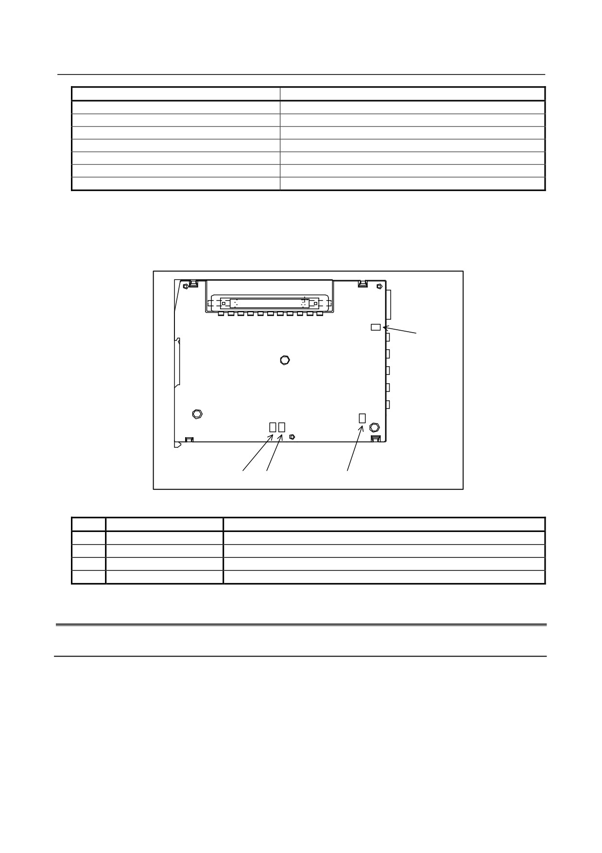
Status indication LEDs are installed on the board in the basic unit case. Two green LEDs (POWER and
OPEN) and two red LEDs (ERR1 and ERR2) are provided. The locations and meanings of the LEDs are
indicated below.
POWER
ERR1,ERR2
LINK
LED indication
No.
LED
Meaning
1
POWER
Turned on when the power is on
2
LINK
Turned on when FSSB communication is performed
3
ERR1
Turned on when COP10A (back stage) is disconnected
4
ERR2
Turned on when COP10B (front stage) is disconnected
4.6
PANEL i
4.6.1
Replacing the Battery
The BIOS settings for the PANEL i are held in the LSI device on the PANEL i main board. The power
for this LSI device is backed up with a backup battery mounted on the PANEL i. Even if the main power
is interrupted, no data in the LSI device will be lost.
If the battery voltage drops, the BIOS message “CMOS Battery Low” appears on the screen when the
power is turned on. If the hardware monitor (HardMntr.exe) has been incorporated normally, the monitor
screen automatically opens to display “CMOS Battery : Low” after system start-up. If the alarm is issued,
replace the battery as soon as possible.
If the battery voltage drops further, it becomes impossible to back up the BIOS settings, thus making it
necessary to clear and re-set all the contents. For this reason, FANUC recommends that the battery be
replaced once per year regardless of whether a battery alarm is issued.
- 312 -
B-64485EN/01
4.MAINTENANCE OF THE OTHER UNITS
Before starting replacement work, get the lithium battery
(ordering information: A02B-0200-K102)
ready.
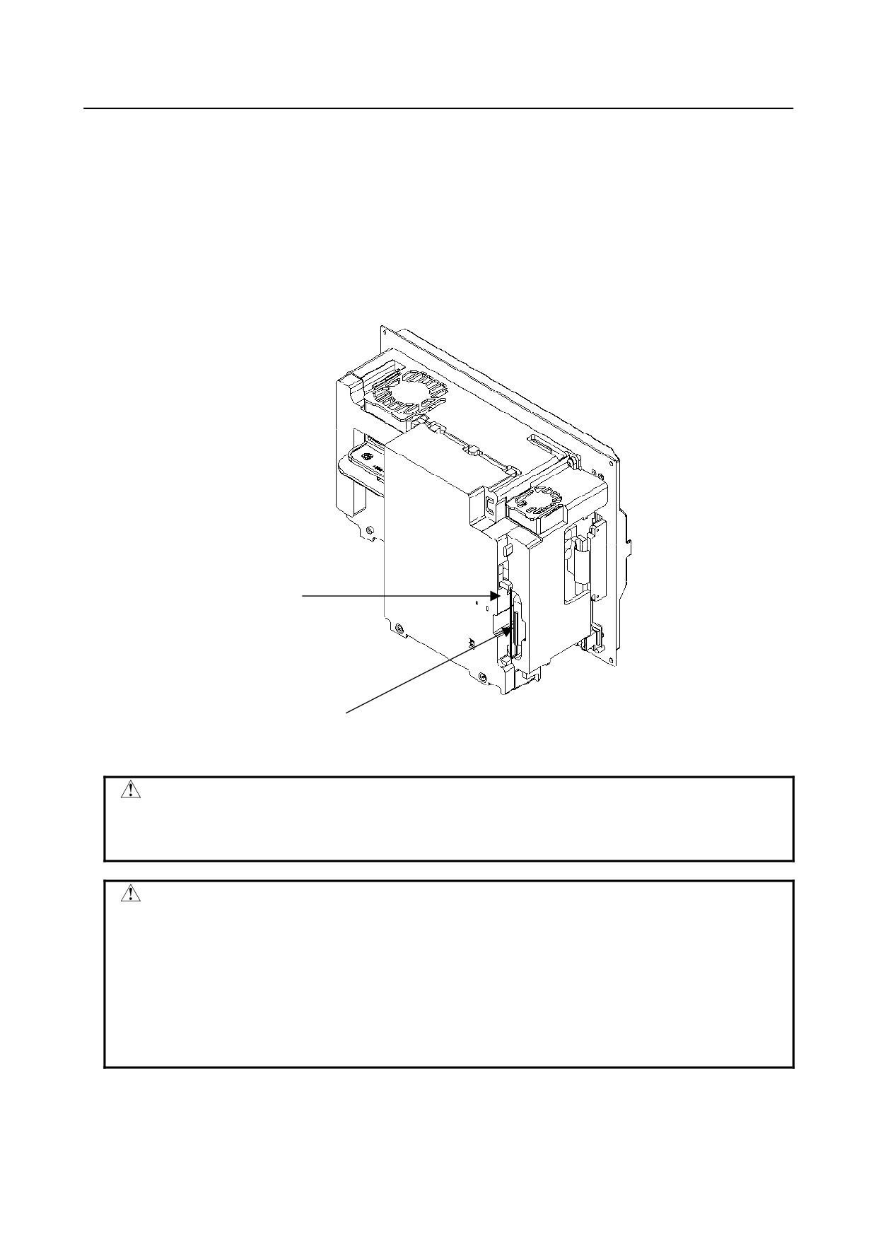
To replace the battery, follow the procedure below:
(1) After keeping the PANEL i turned on for at least 5 seconds, turn off the power, and detach it from
the panel so that you can work from behind.
(2) Remove the connector from the lithium battery and take out the battery from the battery holder.
(3) Insert a new battery into the connector (BAT1) within 5 minutes, and put it into the battery holder.
(4) Re-install the PANEL i.
(5) Turn on the power, and make sure that the BIOS parameters are intact (no error occurs at startup).
Connector
(BAT1)
Lithium battery
A02B-0200-K102
Fig. 4.6.1 Replacing the Battery
WARNING
Using other than the recommended lithium battery may result in the battery
exploding. Replace the battery only with the specified lithium battery
(A02B-0200-K102).
CAUTION
Insert a new battery within 5 minutes after the old battery is removed from the
connector.
Usually, following the battery replacement procedure stated below will not lose
the BIOS settings. Should they be lost, the messages ”251: System CMOS
checksum bad - Default configuration used.” and “Press <F2> to enter SETUP”
appear when the power is turned on.
If you have been using non-default BIOS settings for the PANEL i, re-set them
up exactly. Usually, the unit is used with the default settings.
- 313 -
4.MAINTENANCE OF THE OTHER UNITS
B-64485EN/01
NOTE
After replacement, dispose the used battery as “industrial waste” correctly
according to the laws of the country where the machine is installed and the
ordinances of the local government having jurisdiction over the site of the
machine. When disposing the battery, insulate it, for example, by taping its
electrodes in order to prevent a short circuit.
4.6.2
Replacing the Fan
4.6.2.1 Replacing the fan in the PANEL i
(1) Turn off the power to the PANEL i.
(2) Get a new fan ready.
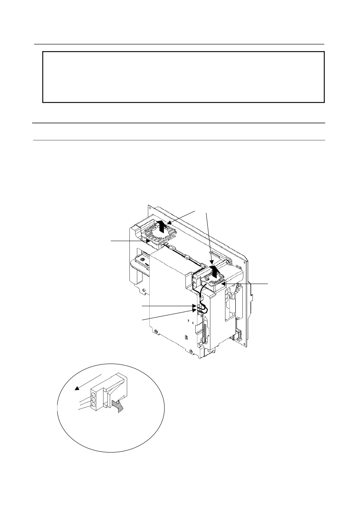
(3) Detach the connector from the fan in the PANEL i. The connector is latched. Pull it out by
unlatching it with a flat-blade screwdriver as shown below.
(4) Replace the fan. Be careful not to mount it in the wrong orientation.
(5) Attach the connector of the new fan correctly; 60-mm-square fan (A08B-0084-K101) to CPE11B
and 40-mm-square fan (A08B-0084-K100) to CPB11.
Air Flow
60-mm-square fan
A08B-0084-K101
Be careful not to
mount the fan in the
wrong orientation.
40-mm-square fan
A08B-0084-K100
Be careful not to
mount the fan in the
wrong orientation.
(40mm-mm-square fan) CPE11A
(60mm-mm-square fan) CPE11B
Pull out the connector by
unlatching it gently with a
flat-blade screwdriver. Do not
pull it hard, or it may be
damaged.
Fig. 4.6.2(a) Replacing the Fan
- 314 -
B-64485EN/01
4.MAINTENANCE OF THE OTHER UNITS
4.6.2.2 Replacing the fan for the HDD
(1) Turn off the power to the PANEL i.
(2) Get a new fan ready.
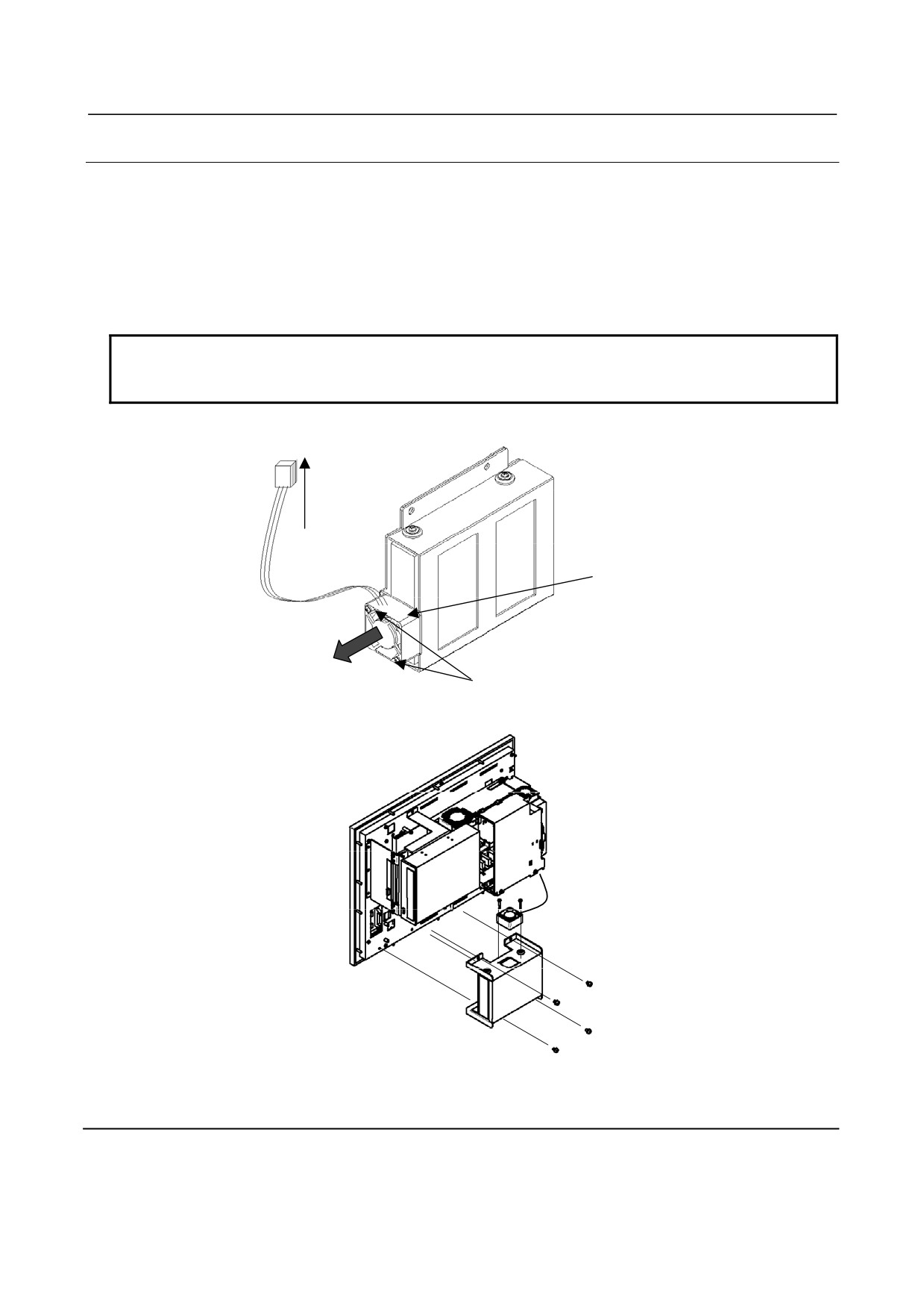
(3) Remove the fan connector (CPE11C) from the power supply board. The connector is latched. Detach
it by pulling it up slightly to unlatch.
(4) Remove the two fastening screws from the fan to detach the fan.
(5) Fasten the new fan with two screws. Attach it to the connector (CPE11C). Be careful not mount it in
the wrong orientation.
NOTE
Before replacing a fan in a unit designed to the automotive manufacture’s
specification, remove the HDD unit.
To power supply P.C.B.
CPE11C (3 pins)
Fan
A08B-0084-K102
Be careful not to
mount the fan in the
wrong orientation.
Air Flow
Two screws
Fig. 4.6.2(b) Replacing the fan for the HDD
Fig. 4.6.2 (c) Replacing the fan for the HDD (for unit designed to automotive manufacture’s specification)
4.6.3
Replacing the Touch Panel Protection Sheet
For the PANEL i with a touch panel, the surface of the touch panel is covered with the protection sheet to
protect it. When there are flaws and contamination on this protection sheet that make the screen hard to
read, replace the protection sheet. See Section 3.12 for explanations about how to replace the touch panel
protection sheet.
- 315 -

4.MAINTENANCE OF THE OTHER UNITS
B-64485EN/01
4.7
REPLACING BATTERY FOR ABSOLUTE PULSECODERS
4.7.1
Overview
• When the voltage of the batteries for absolute Pulsecoders becomes low, alarm 307 or 306 occurs,
with the following indication in the CNC state display at the bottom of the CNC screen.
Alarm 307 (alarm indicating the voltage of the battery becomes low) :
The indication "APC" blinks in reversed display.
Alarm 306 (battery zero alarm) :
The indication "ALM" blinks in reversed display.
• When alarm 307 (alarm indicating the voltage of the battery becomes low) occurs, replace the
battery as soon as possible. In general, the battery should be replaced within one or two weeks,
however, this depends on the number of Pulsecoders used.
• When alarm 306 (battery zero alarm) occurs, Pulsecoders are reset to the initial state, in which
absolute positions are not held. Alarm 300 (reference position return request alarm) also occurs,
indicating that reference position return is required.
• In general, replace the batteries periodically within the service life listed below.
-
A06B-6050-K061 or D-size alkaline dry cells (LR20) : Two years
(for each six-axis
configuration)
-
A06B-6114-K504 : One year (for each three-axis configuration)
NOTE
The above values indicate the estimated service life of batteries used with
FANUC absolute Pulsecoders. The actual battery service life depends on the
machine configuration based on, for example, detector types. For details, contact
the machine tool builder.
4.7.2
Replacing Batteries
To prevent absolute position information in absolute Pulsecoders from being lost, turn on the machine
power before replacing the battery. The replacement procedure is described below.
<1> Ensure that the power to the servo amplifier is turned on.
<2> Ensure that the machine is in the emergency stop state (the motor is inactive).
<3> Ensure that the DC link charge LED of the servo amplifier is off.
<4> Detach the old batteries and attach new ones.
The replacement of the batteries in a separate battery case and the replacement of the battery built into the
servo amplifier are described below in detail.
- 316 -
B-64485EN/01
4.MAINTENANCE OF THE OTHER UNITS
WARNING
• The absolute Pulsecoder of each of the αi/αi S series servo motors and the βi S
series servo motors (βi S0.4 to βi S22) has a built-in backup capacitor.
Therefore, even when the power to the servo amplifier is off and the batteries
are replaced, reference position return is not required if the replacement
completes within less than 10 minutes. Turn the power on and replace the
batteries if the replacement will take 10 minutes or more.
• To prevent electric shock, be careful not to touch metal parts in the power
magnetics cabinet when replacing the batteries.
• Because the servo amplifier uses a large-capacitance electrolytic capacitor
internally, the servo amplifier remains charged for a while even after the power is
turned off. Before touching the servo amplifier for maintenance or other
purposes, ensure your safety by measuring the residual voltage in the DC link
with a tester and confirming that the charge indication LED (red) is off.
• Be sure to replace the batteries with specified ones. Pay attention to the battery
polarity. If a wrong type of battery is used or a battery is installed with incorrect
polarity, the battery may overheat, blow out, or catch fire, or the absolute
position information in the absolute Pulsecoders may be lost.
• Ensure that the battery connector is inserted in the correct position.
4.7.3
Replacing the Batteries in a Separate Battery Case
Use the following procedure to replace the batteries in the battery case.
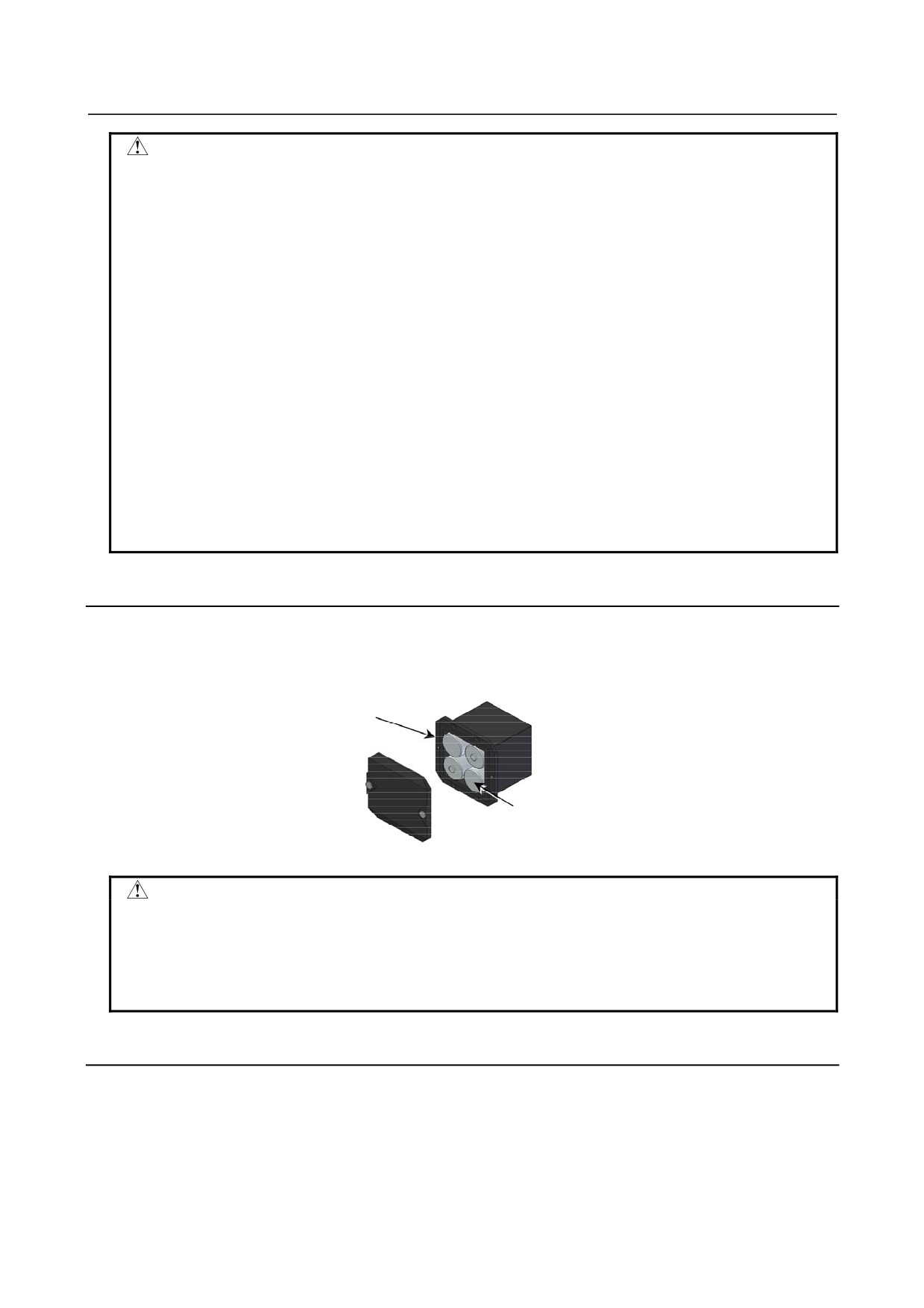
<1> Loosen the screws on the battery case and detach the cover.
<2> Replace the batteries in the case (pay attention to the polarity).
<3> Attach the cover to the battery case.
Battery case (with a cover)
A06B-6050-K060
Batteries
Four A06B-6050-K061 batteries or
D-size alkaline dry cells
CAUTION
• Four D-size alkaline dry cells (LR20) that are commercially available can be
used as batteries. A set of four A06B-6050-K061 batteries is optionally available
from FANUC.
• Replace all the four batteries with new ones. If old and new batteries are mixed,
the absolute position information in the absolute Pulsecoders may be lost.
4.7.4
Replacing the Battery Built into the Servo Amplifier
Use the following procedure to replace the special lithium battery.
<1> Detach the battery cover.
<2> Replace the special lithium battery.
<3> Attach the battery cover.
- 317 -
4.MAINTENANCE OF THE OTHER UNITS
B-64485EN/01
CAUTION
• Purchase the battery from FANUC because it is not commercially available. It is
therefore recommended that you have a backup battery.
• When the built-in battery is used, do not connect BATL (B3) of connector
CXA2A/CXA2B. Also, do not connect two or more batteries to the same BATL
(B3) line. These connections are dangerous because battery output voltages
may be short-circuited, causing the batteries to overheat.
• Install the battery in the servo amplifier in a direction that allows slack in the
cable. If the battery cable is under tension, a bad connection may occur.
• If the +6 V pin and 0 V pin are short-circuited, the battery may overheat, blow
out, or catch fire, or the absolute position information in the absolute
Pulsecoders may be lost.
• When inserting the connector, align it to the connector pins.
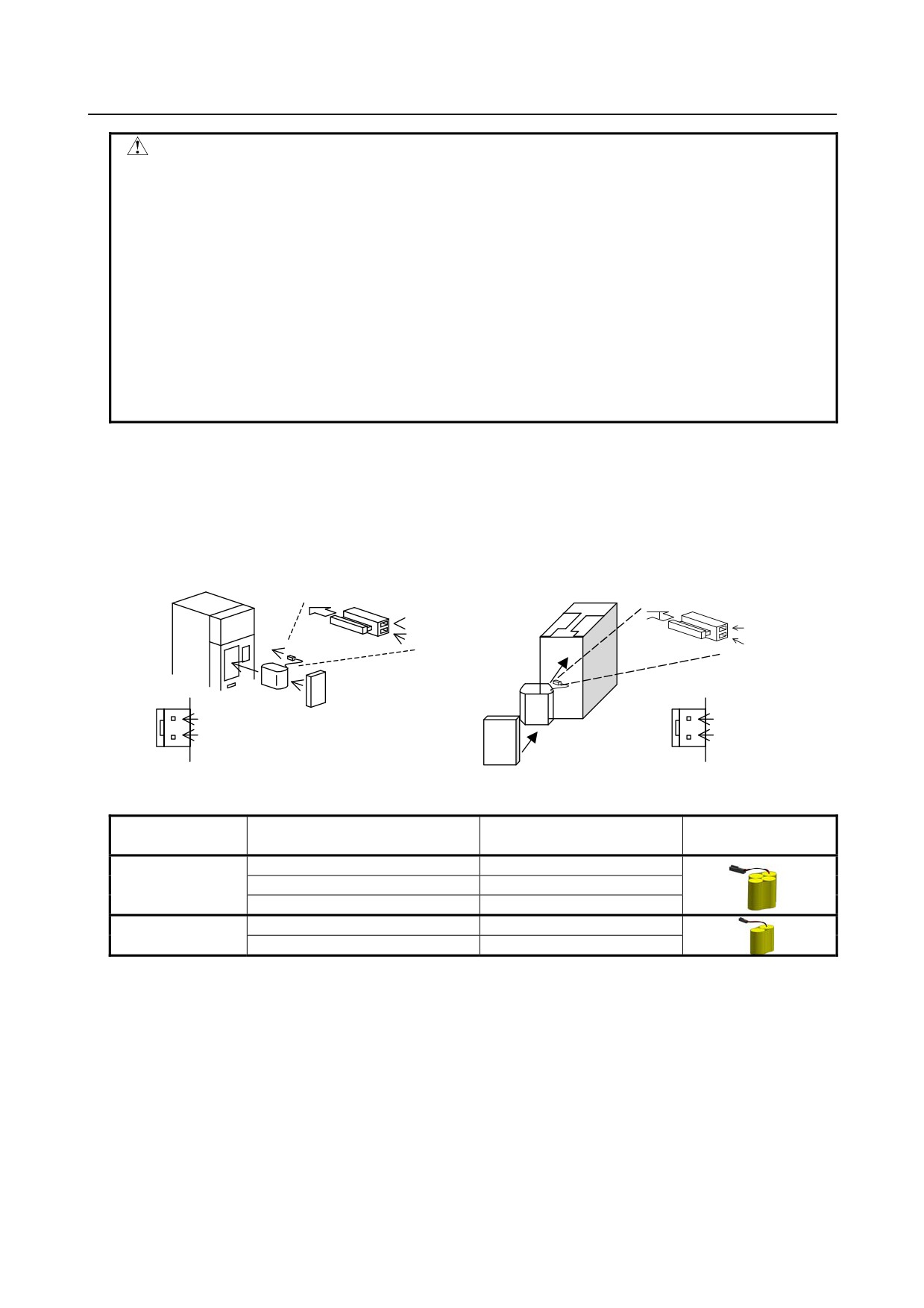
[Connecting the battery]
The battery for the βiSV4 and βiSV20 series amplifiers is mounted in the battery case on the underside of
each of the amplifiers.
The battery for the other βi series amplifiers and the αi series amplifiers is mounted at the front of each of
the amplifiers.
[αi series][βi series βi SV40, βi SV80]
[βi series βi SV4, βi SV 20]
Insertion direction
Cable side
Insertion direction
Cable side
Red: +6 V
Red: +6 V
Connector
Black: 0 V
Connector
Black: 0 V
CX5X
CX5X
Battery
+6 V
Battery case
+6 V
0 V
Battery
0 V
Battery case
[Battery sets and outlines]
Battery ordering
Battery case ordering
Applicable servo amplifier
Outline
drawing number
drawing number
αi series
60/90 mm width
A06B-6114-K505
A06B-6114-K504
αi series
150/300 mm width
A06B-6114-K506
βi series βi SV (two-axis model)
A06B-6114-K505
βi series βiSV4, βiSV20
A06B-6093-K002
A06B-6093-K001
βi series βiSV40, βiSV80
A06B-6093-K002
Used batteries
Old batteries should be disposed as "INDUSTRIAL WASTES" according to the regulations of
the
country or autonomy where your machine has been installed.
- 318 -
B-64485EN/01
5.INPUT AND OUTPUT OF DATA
5 INPUT AND OUTPUT OF DATA
After you change a FROM/SRAM module, you must set various data again. This chapter explains how to
input data (such as parameters, part programs, and tool offset values) to external I/O devices (such as a
floppy disk drive) and to output it from them.
5.1 SETTING PARAMETERS FOR INPUT/OUTPUT
319
5.2 INPUTTING/OUTPUTTING DATA
320
5.3 AUTOMATIC DATA BACKUP
327
5.1
SETTING PARAMETERS FOR INPUT/OUTPUT
Setting procedure of parameters
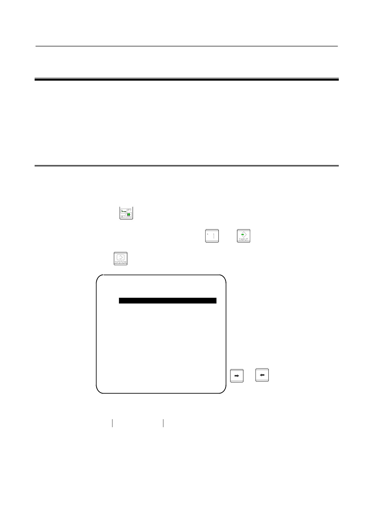
Parameter writing is enabled with following steps 1 to 3.
1
Set to MDI mode or emergency stop state.
2
Press function key
several times or press soft key
[SETTING] to display SETTING
(HANDY) screen.
3
Set the cursor to PARAMETER WRITE and, press
and
keys in this order. Here alarm
100 will be displayed.
4
Press function key
several times to display the following screen.
PARAMETER
(SETTING)
O1234 N12345
0000
SEQ
INI ISO TVC
0
0
0
0
0
0
0
0
0001
FCV
0
0
0
0
0
0
0
0
0012 RMV
MIR
X
0
0
0
0
0
0
0
0
Y
0
0
0
0
0
0
0
0
Z
0
0
0
0
0
0
0
0
B
0
0
0
0
0
0
0
0
0020 I/O CHANNEL
To make the cursor
display in bit unit,
press the cursor key
S
0
T0000
or
REF
****
***
***
10: 15: 30
[ F SRH ][ READ
][ PUNCH ][DELETE ][
]
5
Press soft key [(OPRT)] and the following operation menu is displayed.
<1> Soft key [NO. SRH] : Searched by number.
Examination)
Parameter number → [NO. SRH].
<2> Soft key [ON : 1]
: Item with cursor position is set to 1 (bit parameter)
<3> Soft key [OFF : 0]
: Item with cursor position is set to 0 (bit parameter)
<4> Soft key [+INPUT]
: Input value is added to the value at cursor (word type)
<5> Soft key [INPUT]
: Input value is replaced with the value at cursor (word type)
<6> Soft key [READ]
: Parameters are input from reader/puncher interface.
<7> Soft key [PUNCH]
: Parameters are output to reader/puncher interface.
- 319 -
5.INPUT AND OUTPUT OF DATA
B-64485EN/01
6
After the parameters have been input, set PARAMETER WRITE on the SETTING screen to 0. Press
to release alram 100.
7
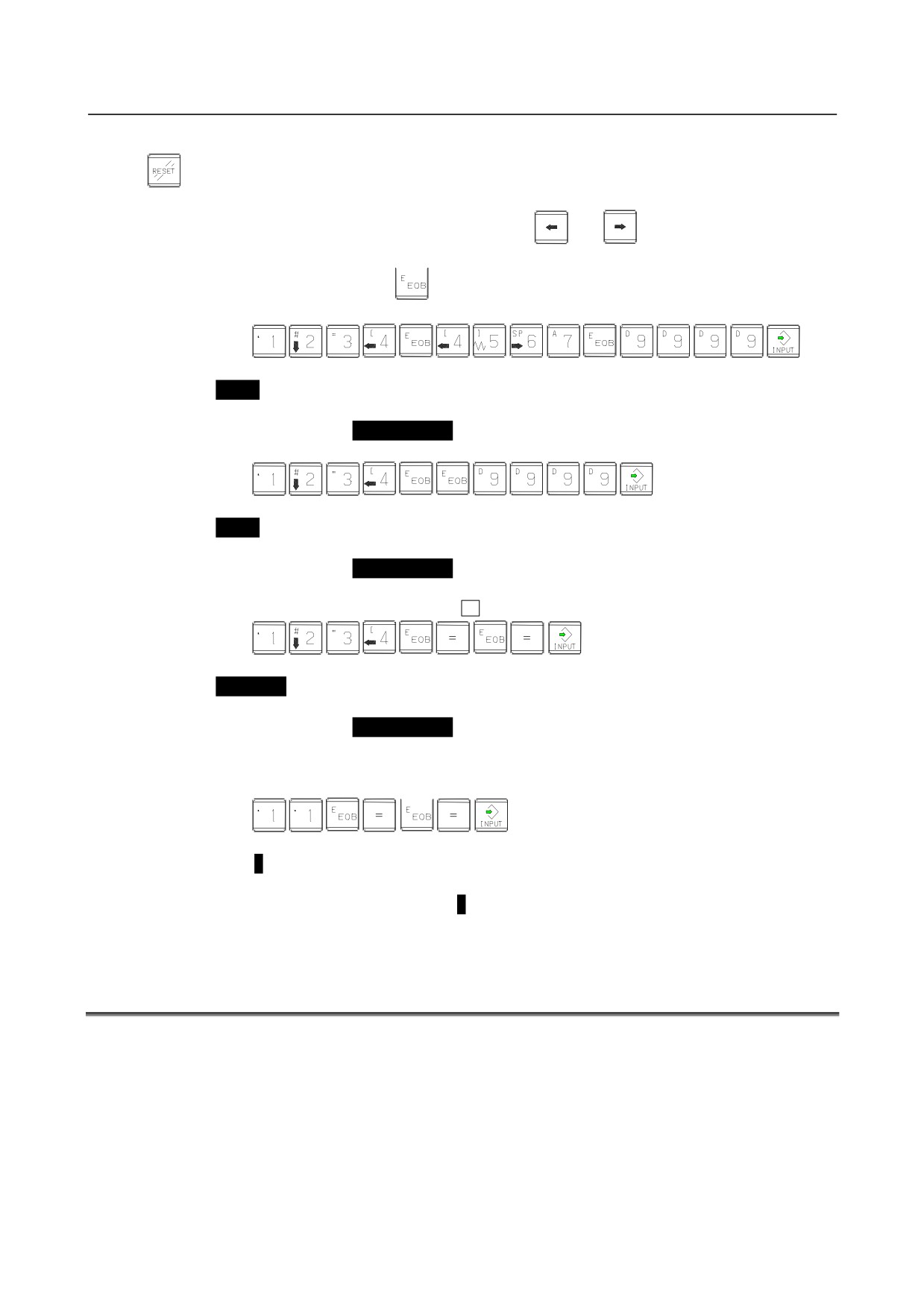
Convenient method
<1> To change parameters in bit unit, press cursor key
or
, then the cursor becomes bit
length and you can set parameters bit by bit (Bit parameter only).
<2> To set data consecutively, use
key.
(Ex.1)
This key sequence sets data as follows:
0
1234
0
⇒
4567
0
9999
0
0
(Ex.2)
This key sequence sets data as follows:
0
1234
0
⇒
0
0
9999
0
0
<3> To set the same data sequentially, press
=
(Ex.1)
This key sequence sets data as follows:
0
1234
0
⇒
1234
0
1234
0
0
<4> Bit parameters can be set as follows:
(Ex.1)
This key sequence sets data as follows:
0 0 0 0 0 0 0 0
0 0 0 1 1 0 0 0
0 0 0 0 0 0 0 0
⇒
0 0 0 1 1 0 0 0
0 0 0 0 0 0 0 0
0 0 0 1 1 0 0 0
0 0 0 0 0 0 0 0
0 0 0 0 0 0 0 0
8
After the required parameters are set, set PARAMETER WRITE to 0.
5.2
INPUTTING/ OUTPUTTING DATA
The CNC memorized the following data.
Outputting the data 1/O device while the CNC is rurnning normally.
(1) CNC paramter
(2) PMC parameter
(3) Pitch error compensation amount
(4) Custom macro variable values
(5) Tool compensation amount
(6) Part program (machining program, custom macro program)
- 320 -

B-64485EN/01
5.INPUT AND OUTPUT OF DATA
5.2.1
Confirming the Parameters Required for Data Output
Be sure that data output cannot be done in an alarm status.
Parameters required for output are as follows :
In addition, (*) indicates the standard setting for input/output devices made by FANUC. Change these
settings according to the unit you actually use.
(Parameter can be changed in MDI mode or emergency stop status.)
#7
#6
#5
#4
#3
#2
#1
#0
0000
ISO
ISO 0: Output with EIA code
1: Output with ISO code (FANUC cassette)
NOTE
1 The I/O setting of a memory card is made by bit 0 (ISO) of
parameter No. 0139.
2 The I/O setting of an USB memory is made by bit 0 (ISU) of
parameter No. 11505.
0020
Selection of I/O channel
(*)
0 : Channel 1 (JD56A of mother board)
1 : Channel 1 (JD56A of mother board)
2 : Channel 2 (JD36A of mother board)
4 : Memory card interface
17 : USB memory interface
NOTE
An operation example shown here assumes that data input/ output
is performed with an input/output unit connected to the JD56A. (I/O
channel = 0)
#7
#6
#5
#4
#3
#2
#1
#0
0101
NFD
ASI
SB2
NFD 0 : Feed is output when data is output.
1 : Feed is not output when data is output.
ASI(*) 0 : EIA or ISO code is used for input/output data.
1 : ASCII code is used.
SB2 0 : No. of stop bits is 1.
(*)
1 : No. of stop bits is 2.
0102
Number specified fot the input/output device
Set value
Input/output device
0
RS-232-C (Used control codes DC1 to DC4)
1
FANUC CASSETTE ADAPTOR 1 (FANUC CASSETTE B1/B2)
2
FANUC CASSETTE ADAPTOR 3 (FANUC CASSETTE F1)
FANUC PROGRAM FILE Mate, FANUC FA Card Adaptor
3
FANUC FLOPPY CASSETTE ADAPTOR, FANUC Handy File
FANUC SYSTEM P-MODEL H
4
RS-232-C (Not used control codes DC1 to DC4)
5
Portable tape reader
- 321 -

5.INPUT AND OUTPUT OF DATA
B-64485EN/01
Set value
Input/output device
FANUC PPR
6
FANUC SYSTEM P-MODEL G, FANUC SYSTEM P-MODEL H
0103
Baud Rate
1:
50
7:
600
11:
9600
3:
110
8:
1200
12:
19200 [BPS]
4:
150
9:
2400
6:
300
(*)10: 4800
#7
#6
#5
#4
#3
#2
#1
#0
0139
ISO
ISO
0: Output with ASCII code
1: Output with ISO code (memory card)
WARNING
1 Unless data is input using ASCII codes, set this parameter to 1 to
input or output data using ISO codes.
2 Data input/output with ASCII codes is dangerous because parity
information is not included and a data error during the data
input/output is not detected.
3 DNC operation from a memory card also must set the parameter to
1, and execute DNC operation by ISO code. ASCII codes is
dangerous because parity information is not included and a data
error during the data input is not detected.
NOTE
A tool (FANUC ISO Converter) for converting data from ASCII code
to ISO code on a commercial PC is available from FANUC.
#7
#6
#5
#4
#3
#2
#1
#0
11505
ISU
ISU
0: Output with ASCII code
1: Output with ISO code (USB memory)
WARNING
1 Unless data is input using ASCII codes, set this parameter to 1 to
input or output data using ISO codes.
2 Data input/output with ASCII codes is dangerous because parity
information is not included and a data error during the data
input/output is not detected.
NOTE
A tool (FANUC ISO Converter) for converting data from ASCII code
to ISO code on a commercial PC is available from FANUC.
5.2.2
Outputting CNC Parameters
1
Enter EDIT mode or the emergency stop condition.
2
Press function key
and soft key [PARAMETER] to select a parameter screen.
- 322 -
B-64485EN/01
5.INPUT AND OUTPUT OF DATA
3
Press soft key [(OPRT)] and continuous menu key
4
Press soft key [PUNCH] and [EXEC],and the parameters are started to be output.
5.2.3
Outputting Pitch Error Compensation Amount
1
Select EDIT mode.
2
Press the function key
and continuous menu key
several times, then press [PITCH] to
select the pitch error compensation setting screen.
3
Press soft key [(OPRT)] and continuous menu key
4
Press soft key [PUNCH] and [EXEC], then pitch error compensation amount is started to be output.
5.2.4
Outputting Custom Macro Variable Values
When custom macro function is equipped, values of variable No. 500 and later are output.
1
Press function key
2
Press continuous menu key
and soft key [MACRO] to select custom macro variable screen.
3
Press soft key [(OPRT)] and then continuous menu key
4
Press soft key [PUNCH] and [EXEC], then custom macro variable values are output.
5.2.5
Outputting Tool Compensation Amount
1
Select EDIT mode.
2
Press function key
and soft key [OFFSET] to display the tool compensation amount screen.
3
Press [(OPRT)] key and continuous menu key
4
Press soft key [PUNCH] an [EXEC] key, and the tool compensation amount is started to be output.
5.2.6
Outputting Part Program
1
Confirm the following parameters. If this parameter is set to 1, rather than the value indicated by l,
change to MDI mode and then reset to 0.
However, if you changed the parameter setting, restore the original value after finishing this work.
#7
#6
#5
#4
#3
#2
#1
#0
3202
NE9
NE8
NE9(*) 0: Programs of 9000s are edited.
1: Programs of 9000s can be protected. (Protected programs are not output.)
NE8 (*) 0: Programs of 8000s are edited.
1: Programs of 8000s can be protected.
(Protected programs are not output.)
2
Select EDIT mode.
3
Press function key
and press soft key [PROGRAM] to display program text.
4
Press [(OPRT)] key and press continuous menu key
5
Input a program number to be output. To output all programs input as:
6
Press [PUNCH] and [EXEC] key, then program output is started.
- 323 -
5.INPUT AND OUTPUT OF DATA
B-64485EN/01
5.2.7
Inputting CNC Parameters
1
Set to the emergency stop state.
2
Confirm that the patameters required to input data is correct.
In addition, (*) indicates the standard setting for input/output devices made by FANUC. Change
these settings according to the unit you actually use.
<1> Press function key
several times, and press [SETING] to display SETTING screen.
<2> Confirm that PARAMETER WRITE=1.
<3> Press function key
to select the parameter screen.
<4>
0020
Selection of I/O channel
(*)
0: Channel 1 (JD56A of mother board)
1: Channel 1 (JD56A of mother board)
2: Channel 2 (JD36A of mother board)
4: Memory card interface
17 : USB memory interface
<5>
#7
#6
#5
#4
#3
#2
#1
#0
0101
NFD
ASI
SB2
NFD 0: Feed is output when punching out.
1: Feed is not output when punching out.
ASI 0: EIA or ISO code is used.
1: ASCII code is used.
SB2 0: No. of stop bits is 1.
(*)
1: No. of stop bits is 2.
<6>
0102
Specification number of I/O device
Set value
Input/output device
0
RS-232-C (Used control codes DC1 to DC4)
1
FANUC CASSETTE ADAPTOR 1 (FANUC CASSETTE B1/B2)
2
FANUC CASSETTE ADAPTOR 3 (FANUC CASSETTE F1)
FANUC PROGRAM FILE Mate, FANUC FA Card Adaptor
3
FANUC FLOPPY CASSETTE ADAPTOR, FANUC Handy File
FANUC SYSTEM P-MODEL H
4
RS-232-C (Not used control codes DC1 to DC4)
5
Portable tape reader
FANUC PPR
6
FANUC SYSTEM P-MODEL G, FANUC SYSTEM P-MODEL H
<7>
0103
Baud rate
1:
50
7:
600
11:
9600
3:
110
8:
1200
12:
19200 [BPS]
4:
150
9:
2400
6:
300
(*)10: 4800
3
Press continuous menu key
4
Press soft key [READ] and [EXEC]. Then input of parameters are started.
- 324 -

B-64485EN/01
5.INPUT AND OUTPUT OF DATA
5
Upon completion of parameter input, turn off the power then turn on the power again.
6
Alarm 300 is issued if the system employs an absolute pulse coder. In such a case, perform reference
position return again.
#7
#6
#5
#4
#3
#2
#1
#0
0139
ISO
ISO
0: Output with ASCII code
1: Output with ISO code (memory card)
WARNING
1 Unless data is input using ASCII codes, set this parameter to 1 to
input or output data using ISO codes.
2 Data input/output with ASCII codes is dangerous because parity
information is not included and a data error during the data
input/output is not detected.
3 DNC operation from a memory card also must set the parameter to
1, and execute DNC operation by ISO code. ASCII codes is
dangerous because parity information is not included and a data
error during the data input is not detected.
NOTE
A tool (FANUC ISO Converter) for converting data from ASCII code
to ISO code on a commercial PC is available from FANUC.
#7
#6
#5
#4
#3
#2
#1
#0
11505
ISU
ISU
0: Output with ASCII code
1: Output with ISO code (USB memory)
WARNING
1 Unless data is input using ASCII codes, set this parameter to 1 to
input or output data using ISO codes.
2 Data input/output with ASCII codes is dangerous because parity
information is not included and a data error during the data
input/output is not detected.
NOTE
A tool (FANUC ISO Converter) for converting data from ASCII code
to ISO code on a commercial PC is available from FANUC.
5.2.8
Inputting Pitch Error Compensation Amount
1
Release the emergency stop and select EDIT mode.
2
Confirm that PARAMETER WRITE=1 on the setting screen.
3
Press function key
and soft key [PROGRAM] to display program contents.
4
Press function key
several times, soft key
[PARAM], continuous menu key
and
[PITCH] to select the screen for pitch error compensation amount.
5
Press the function key
and continuous menu key
several times, then press [PITCH] to
select the pitch error compensation setting screen.
- 325 -
5.INPUT AND OUTPUT OF DATA
B-64485EN/01
6
Press soft key [(OPRT)] and continuous menu key
7
Press soft key [READ] and [EXEC], then the pitch error compensation amount is started to be input.
8
After data has been input, press function key
twice to display the SETTING screen and return
the PARAMETER WRITE to 0.
5.2.9
Inputting Custom Macro Variable Values
* If the system is equipped with the custom macro fucntion, input the variable values.
1
Select EDIT mode.
2
Press function key
then soft key [PROGRAM] to display program contents.
3
Press the function key
and press continuous menu key
several times, then press
[PITCH] to select the pitch error compensation setting screen.
4
Press soft key [(OPRT)] and continuous menu key
5
Press soft key [READ] and [EXEC], then the pitch error compensation amount is started to be input.
5.2.10 Inputting Tool Compensation Amount
1
Select EDIT mode.
2
Turn off the program protect (KEY=1).
3
Press function key
, and soft key [OFFSET] to display the tool compensation amount screen.
4
Press soft key [(OPRT)] and continuous menu key
5
Press [READ] key and [EXEC] key and data input is started.
5.2.11 Inputting Part Programs
Confirm the following parameters. If the setting is different from the value indicated by (*), reset to the
specified value only during this work. (Change it in MDI mode).
#7
#6
#5
#4
#3
#2
#1
#0
3201
NPE
RAL
NPE When programs are registered in part program storage area, M02,M30 and M99 are:
0: Regarded as the end of program.
(*)
1: Not regarded as the end of porgram.
RAL When programs are registered:
(*)
0: All programs are registered.
1: Only one program is registered.
#7
#6
#5
#4
#3
#2
#1
#0
3202
NE9
NE8
NE9 (*) 0: Programs of 9000s can be edited.
1: Programs of 9000s are protected.
NE8 (*) 0: Programs of 8000s can be edited.
1: Programs of 8000s are protected.
* For PPR, item 4 is not required.
1
Confirm that mode is EDIT mode.
2
Turn off the program protect (KEY3=1).
- 326 -
B-64485EN/01
5.INPUT AND OUTPUT OF DATA
3
Press function key
and press soft key [PROGRAM] to select a part program file.
4
Press soft key [READ] and [EXEC], then data input is started.
5.3
AUTOMATIC DATA BACKUP
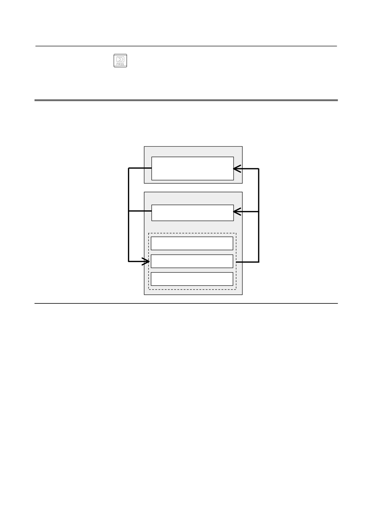
It is possible to back up data held in the CNC’s FROM/SRAM by storing it automatically in the FROM,
which requires no battery and to restore the baked-up data as required. If data is lost from the CNC due to
unforeseen circumstances, this function can be used to restore the data easily.
Also, it is possible to hold up to three occurrences of backup data. With this function, the CNC data can
be quickly switched to a post-machine adjustment state or an arbitrary backup state.
SRAM (requires batteries)
All types of data, such as
Backup
parameters and offset data, in
SRAM
FROM (requires no battery)
NC programs and directory
information
Backup data 1
Backup data 2
Restore
Backup data 3
Explanation
-
Data to be backed up
Data in the CNC is backed up by storing it in the FROM, which requires no battery.
• NC programs and directory information held in the FROM (which requires no battery)
• Various types of data, such as parameters and offset values, held in the SRAM (which requires
batteries)
Setting bit 2 (AAP) of parameter No.10340 to 1 enables NC programs and directory information in the
FROM to be backed up. Set this parameter only when necessary, because the required backup time and
data storage size vary depending on the size of the programs.
Setting parameter No. 10342 enables up to 3 occurrences of backup data to be held.
-
Backup modes
The following three backup modes are available.
1.
Automatic backup occurring every time the power is turned on
2.
Automatic backup occurring at intervals of a specified number of days when the power is turned on
3.
Backup started manually at an emergency stop
-
Automatic backup occurring every time the power is turned on
Data in the CNC can be backed up automatically when the power is turned on.
This mode can be used by:
• Setting bit 0 (ABP) of parameter No. 10340 to 1
• Setting parameter No. 10342 to 1 or greater
- 327 -

5.INPUT AND OUTPUT OF DATA
B-64485EN/01
• Setting bit 2 (AAP) of parameter No. 10340 to 1 if also NC programs and directory information in
the FROM must be backed up
-
Automatic backup occurring at intervals of a specified number of days when
the power is turned on
Data in the CNC can be backed up automatically when the power is turned on for the first time in a
specified number of days since the previous backup.
This mode can be used by:
• Selecting the first backup mode (automatic backup occurring every time the power is turned on)
• Setting parameter No. 10341 with a number of days at intervals of which automatic backup is to be
made cyclically
-
Backup started manually at an emergency stop
Data in the CNC can be backed up by starting an appropriate procedure manually in an emergency stop
state. This mode makes it possible to back up data without turning off the power for the CNC at an
arbitrary timing, such as when machining has been set up or before a holiday.
This mode can be used by:
• Setting parameter No. 10342 to 1 or greater
• Setting bit 2 (AAP) of parameter No. 10340 to 1 if also NC programs and directory information in
the FROM must be backed up
[Backup procedure]
1.
Put the machine in an emergency stop state.
2.
Set bit 7 (EEB) of parameter No. 10340 to 1 to start backup. This parameter becomes 0 just after the
backup sequence has started.
3.
The execution status of backup can be checked with No. 1016 on the diagnosis screen described
later.
NOTE
It takes time since the beginning of backup till the end of backup. So, if data being
backed up is updated, it is likely that a mismatch may occur between the original
data and backup data. When updating data in the CNC at an emergency stop,
watch the automatic data backup in-progress signal ATBK and perform
appropriate processing.
-
Backup execution status
In the backup modes used at power-on time, 10 dots “.” are used to indicate the execution status of
backup. For example, the completion of backup is indicated with: “AUTO BACKUP : ……….END
The diagnosis screen can also be used to check the execution status of backup as follows:
• No.1016#0 (AEX): Backup in progress
• No.1016#6 (ACM): Backup completed
• No.1016#7 (ANG): Error during backup
• No.1016#1 (DT1), #2 (DT2), #3 (DT3): Updated data
-
Write-protected backup data
Factory-set or post-adjustment machine status data can be held as write-protected backup data by
specifying the number of pieces of backup data to 2 or greater with parameter No. 10342. The first piece
of backup data is handled as write-protected backup data.
This function is enabled by:
• Setting bit 1 (ABI) of parameter No. 10340 to 1
• Setting parameter No. 10342 to 2 or greater
• Setting bit 2 (AAP) of parameter No. 10340 to 1 if also NC programs and directory information in
the FROM must be backed up
- 328 -

B-64485EN/01
5.INPUT AND OUTPUT OF DATA
[Backup procedure]
1.
Set bit 6 (EIB) of parameter No. 10340 to 1.
2.
Turn the power for the CNC off and on again. When the power is turned on, the first piece of backup
data is updated automatically, and bit 6 (EIB) of parameter No. 10340 becomes 0.
The second and third pieces of backup data are updated each time another type of backup (automatic
backup occurring every time the power is turned on, automatic backup occurring at intervals of a
specified number of days when the power is turned on, or backup started manually at an emergency stop)
is made.
-
Parity check
A parity check is made at backup. If a parity error is detected, the backup is not completed.
-
Restoring backed-up data
With the BOOT SYSTEM, executing the following procedure can restore backed-up data from FROM.
1
From the BOOT’s TOP menu, select “7. SRAM DATA UTILITY”. The following menu appears.
Select ”3”.
SRAM DATA UTILITY
1.SRAM BACKUP
( CNC -> MEMORY CARD )
2.SRAM RESTORE ( MEMORY CARD -> CNC )
3.AUTO BKUP RESTORE ( FROM -> CNC )
4. END
2.
From the menu below, select data and run restore.
AUTO BACKUP DATA RESTORE
1. BACKUP DATA1 yyyy/mm/dd **:**:**
2. BACKUP DATA2 yyyy/mm/dd **:**:**
3. BACKUP DATA3 yyyy/mm/dd **:**:**
4
END
3.
Exit BOOT.
Signal
Automatic data backup in-progress signal ATBK<F0520.0>
[Classification] Output signal
[Function] This signal is "1" during automatic data backup. When updating data in the CNC at an
emergency stop, perform appropriate processing according to the state of this signal.
Signal address
#7
#6
#5
#4
#3
#2
#1
#0
F0520
ATBK
Parameter
#7
#6
#5
#4
#3
#2
#1
#0
10340
EEB
EIB
AAP
ABI
ABP
[Input type] Parameter input
[Data type] System-common type
#0 ABP Automatic data backup at power-on is:
0: Disabled.
1: Enabled.
- 329 -

5.INPUT AND OUTPUT OF DATA
B-64485EN/01
#1 ABI Overwrite-protected backup data is:
0: Regarded as invalid.
1: Regarded as valid.
#2 AAP Backup of NC programs and directory information in FROM is:
0: Disabled.
1: Enabled.
#6 EIB When the CNC is turned on next, overwrite-protected backup data is:
0: Not updated.
1: Updated.
NOTE
This parameter is valid when 2 or a greater value is set in
parameter No. 10342, and bit 1 (ABI) of parameter No. 10340 is set
to 1.
#7 EEB When an emergency stop occurs, a backup operation is:
0: Not performed.
1: Performed.
NOTE
This parameter is valid when 1 or a greater value is set in
parameter No. 10342.
10341
Interval at which automatic data backup is performed periodically
[Input type] Parameter input
[Data type] Word system-common type
[Unit of data] No unit
[Valid data range] 0 to 365
When automatic data backup is performed periodically, this parameter sets the interval as
the number of days. When the power is turned on after a set number of days has passed
from the date of the previous backup, a backup operation is performed. If 0 is set in this
parameter, this function is disabled.
10342
Number of backup data items
NOTE
When this parameter is set, the power must be turned off before
operation is continued.
[Input type] Parameter input
[Data type] Byte system-common type
[Unit of data] No unit
[Valid data range] 0 to 3
This parameter sets the number of backup data items. If 0 is specified, backup is not
performed.
Diagnosis display
This function enables the status of backup execution to be checked.
- 330 -

B-64485EN/01
5.INPUT AND OUTPUT OF DATA
#7
#6
#5
#4
#3
#2
#1
#0
1016
ANG
ACM
DT3
DT2
DT1
AEX
#0 AEX Indicates whether automatic data backup is being executed, as follows:
0: Not being executed
1: Being executed
#1 DT1 Indicates whether data 1 has been updated in the previous backup, as follows:
0: Not updated
1: Updated
#2 DT2 Indicates whether data 2 has been updated in the previous backup, as follows:
0: Not updated
1: Updated
#3 DT3 Indicates whether data 3 has been updated in the previous backup, as follows:
0: Not updated
1: Updated
#6 ACM Indicates whether automatic data backup has been executed, as follows:
0: Not executed
1: Executed
#7 ANG Indicates whether an error has occurred in automatic data backup, as follows:
0: Not occurred
1: Occurred
Caution
CAUTION
1 A value that can be set in parameter No. 10342 (number of occurrences of
backup data held) is limited according to the program size, SRAM capacity, and
the FROM/SRAM module used.
2 Do not turn off the power for the NC during backup or restoration.
3 If backed-up data is restored, parameters submitted to automatic backup are
returned to the state in which they were when backed up. Change them as
required.
- 331 -
6.INTERFACE BETWEEN CNC AND PMC
B-64485EN/01
6 INTERFACE BETWEEN CNC AND PMC
This section briefly describes the PMC function. It also explains the CNC-PMC interface.
6.1 WHAT IS PMC?
332
6.2 MULTI-PMC FUNCTION
336
6.3 PMC SPECIFICATIONS
346
6.4 OPERATING THE PMC SCREEN
352
6.5 PMC DIAGNOSIS AND MAINTENANCE SCREENS ([PMC MAINTE])
355
6.6 LADDER DIAGRAM MONITOR AND EDITOR SCREENS ([PMC LADDER])
384
6.7 LIST OF ADDRESSES
398
6.1
WHAT IS PMC?
The programmable machine controller (PMC) is a programmable controller (PC) built into a CNC to
perform sequence control for a machine tool (spindle rotation, tool change, machine operator's panel
control, and so on).
Sequence control is to perform control steps successively in a predetermined sequence or according to the
logic operation.
Programs for performing sequence control for machine tools are called sequence programs. Generally,
sequence programs coded in the Ladder language are used.
6.1.1
Basic Configuration of PMC
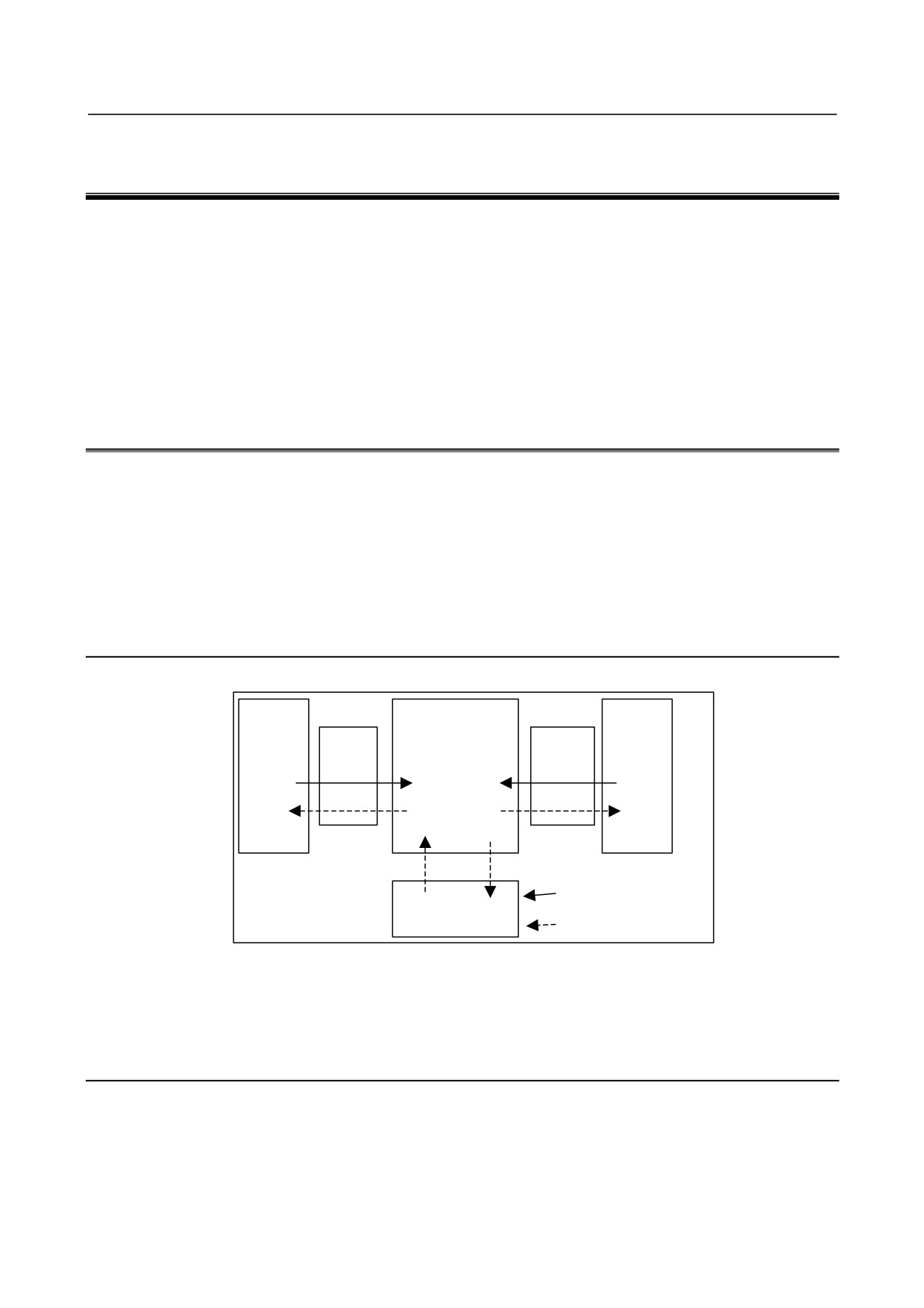
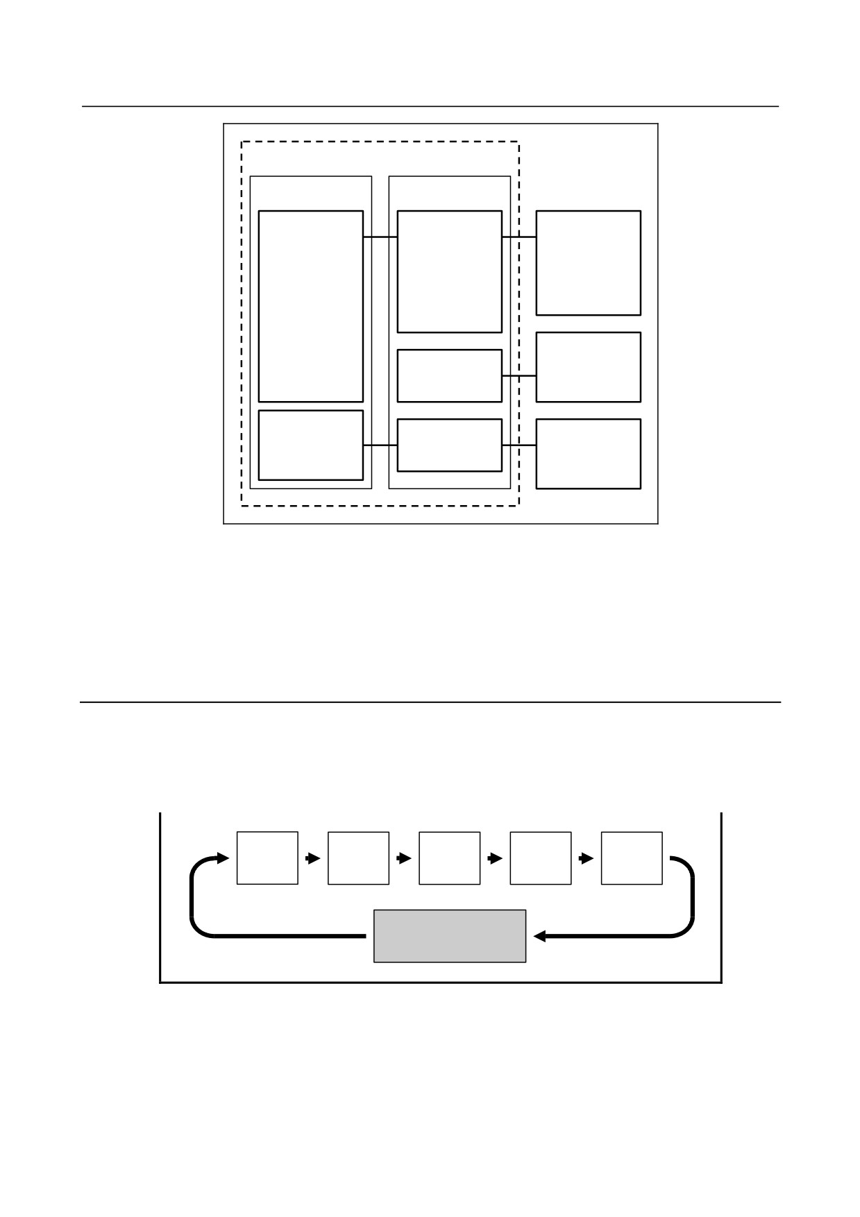
The Fig. 6.1.1 is the basic configuration of the PMC:
CNC
PMC
Machine
Internal
External
I/O
Sequence
I/O
program
Signal input to PMC
Internal relay
Signal output from PMC
Fig. 6.1.1 Basic configuration of PMC
The sequence program reads input signals, performs operations, and outputs results in a predetermined
sequence.
6.1.2
I/O Signals of PMC
Input signals of the PMC include signals input from the CNC (such as M and T function signals) and
signals input from the machine (such as the cycle start button and feed hold signal button). Output signals
of the PMC include signals output to the CNC (such as the cycle start command and feed hold signal
command) and signals output to the machine (such as turret rotation and spindle stop). The PMC controls
these I/O signals by executing a sequence program to control the machine tool.
- 332 -
B-64485EN/01
6.INTERFACE BETWEEN CNC AND PMC
6.1.3
PMC Signal Addresses
PMC signal addresses indicate the locations of I/O signals exchanged with the machine, I/O signals
exchanged with the CNC, and signals for internal relays and data (PMC parameters) in nonvolatile
memory.
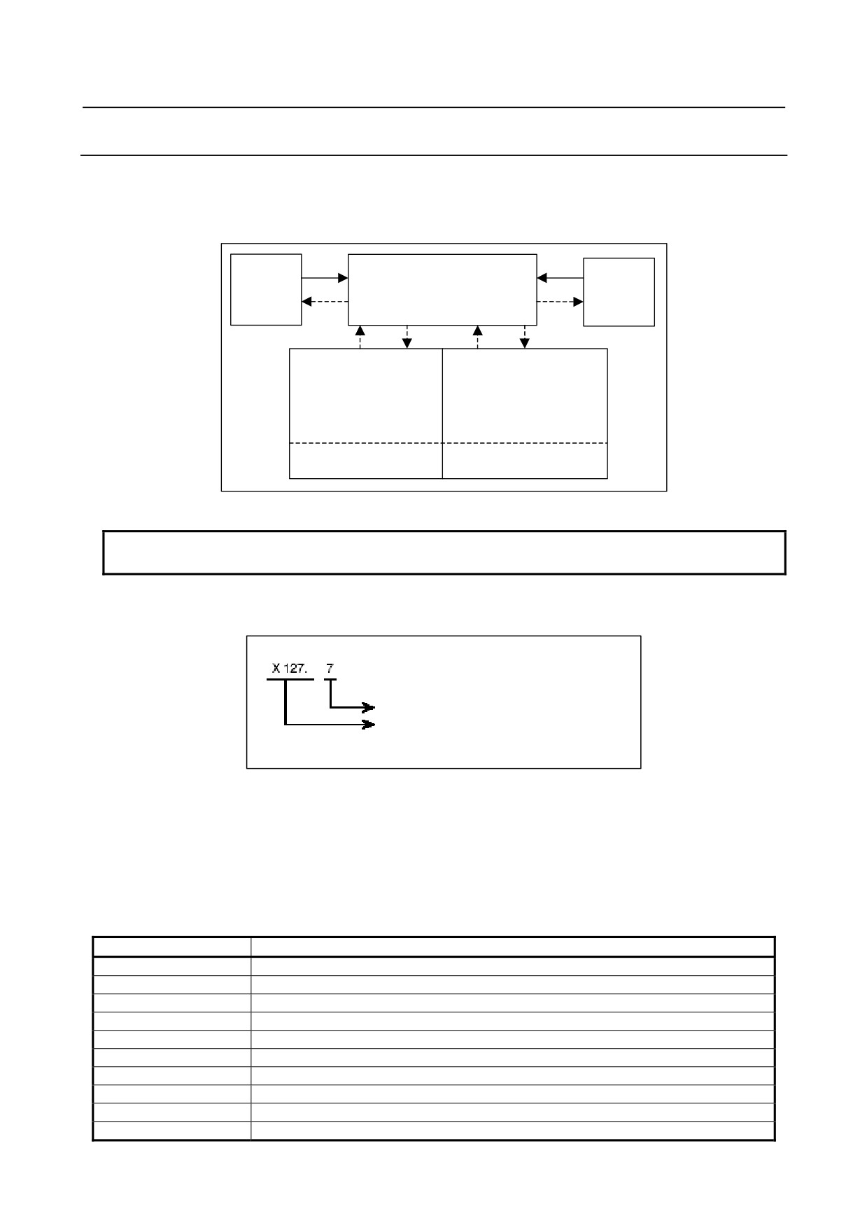
PMC addresses are roughly classified as shown in Fig. 6.1.3 (a).
F
X
Signals
Signals
to/from
PMC
to/from CNC
machine
G
Y
(MT)
Nonvolatile memory
(1) Variable timer (T)
Internal relay (R)
(2) Counter (C)
(3) Keep relay (K)
(4) Data table (D)
Extra relay (E)
(5) Extra relay (E)
(NOTE)
Fig. 6.1.3 (a) PMC-related addresses
NOTE
Optionally, extra relays (E) may be assigned to nonvolatile memory locations.
The PMC signal address format consists of an address number and bit number (0 to 7) as follows (Fig.
6.1.3 (b)):
Bit number (0 to 7)
Address number
(letter followed by decimal
number)
Fig. 6.1.3 (b) PMC address format
The first letter of an address number represents the type of the signal.
In sequence programs, an address of a byte may be specified. In the above example, specify X127 to
specify a byte address. In this case, the period "." and bit number are unnecessary.
Table 6.1.3 lists the address symbols and corresponding signals.
Table 6.1.3 Address Symbols and signal types
Symbol
Signal type
F
Input signal from CNC to PMC (CNC → PMC)
G
Output signal from PMC to CNC (PMC → CNC)
X
Input signal from machine to PMC (MT → PMC)
Y
Output signal from PMC to machine (PMC → MT)
R
Internal relay
E
Extra relay
Z
System relay
A
Message display
T
Variable timer
C
Counter
- 333 -

6.INTERFACE BETWEEN CNC AND PMC
B-64485EN/01
Symbol
Signal type
K
Keep relay
D
Data table
M
Input signal from another PMC path
N
Output signal to another PMC path
L
Label number
P
Subprogram number
(1)
Addresses of signals between the PMC and CNC (F and G)
These addresses are assigned to interface signals between the CNC and PMC. The relationships
between the signals and addresses are defined by the CNC.
F indicates an input signal from the CNC to PMC.
G indicates an output signal from the PMC to CNC.
(2)
Addresses of signals between the PMC and machine (X and Y)
I/O signals exchanged with an externally connected machine can be assigned to any addresses within
an available range to control the machine.
X indicates an input signal from the machine to PMC.
Y indicates an output signal from the PMC to machine.
(3)
Addresses of internal relays and extra relays (R and E)
These addresses are used to temporarily store operation results during sequence program execution
processing.
Optionally, E addresses may be assigned to nonvolatile memory locations.
The address locations of internal relays also include a reserved area used by the PMC system
software. The signals in the reserved area cannot be written by sequence programs.
(4)
System Relay Addresses (Z)
The System Relay is used to control a sequence program by PMC System software. And, some
addresses such as 'Operation results of functional instructions' are used to condition of a sequence
program.
For PMC memories A and B, the system relay addresses are R9000 to R9499.
(5)
Signal addresses for message display (A)
Instruction “DISPB” used in sequence programs include instructions to display a message on the
CNC screen. These addresses are used by such instructions.
(6)
Nonvolatile memory addresses
The contents of these address locations are not erased even when the power is turned off.
These addresses are used for management of the data items listed below. These data items are called
PMC parameters.
(a) Variable timer (T)
(b) Counter (C)
(c) Keep relay (K)
A reserved area used by the PMC system software is partly included.
(d) Data table (D)
(e) Extra relay (E)
Optionally, E addresses may be assigned to nonvolatile memory locations.
These addresses are used to temporarily store operation results during sequence program
execution processing.
(7)
Addresses for multi-path PMC Interface (M, N)
These addresses are used to the Multi-path PMC interface.
- 334 -
B-64485EN/01
6.INTERFACE BETWEEN CNC AND PMC
M indicates an input signal from another PMC path.
N indicates an output signal to another PMC path.
(8) Other addresses
(a) Label number (L)
Sequence program instructions include an instruction to cause a jump to a specified position in
the middle of processing. This address indicates the jump destination used by this instruction.
The contents of L address can not be read/written in sequence program.
(b) Subprogram number (P)
In sequence programs, a main program can call subprograms. P addresses indicate the numbers
of these subprograms. The contents of P address can not be read/written in sequence program.
6.1.4
Communication Method for External I/O Device
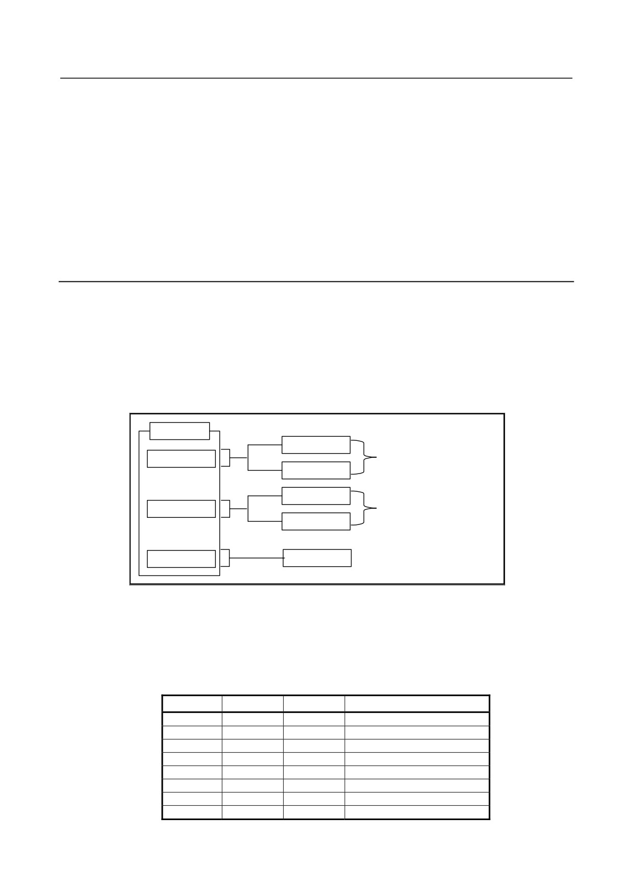
For the high-speed serial interface, which passes input/output signals between the PMC and each I/O
device, there are two communication methods, i.e. the FANUC I/O Link i and the FANUC I/O Link.
You can use up to three channels for the serial interface. The communication method for channel 1 and
channel 2 can be specified by the CNC parameter. The default value “0” of the CNC parameter means
that I/O Link is specified. The channel 3 can be used only for I/O Link.
For the details of the setting of the CNC parameter, see PMC PROGRAMMING MANUAL
(B-64513EN).
CNC
I/O Link i
Channel 1
Select by CNC parameter
I/O Link
I/O Link i
Channel 2
Select by CNC parameter
I/O Link
Channel 3
I/O Link
Fig. 6.1.4(c) Setting of the communication method for each channels
The maximum I/O points of I/O Link i are 2048 poins/2048 points for each channel. The maximum I/O
points of I/O Link are 1024 points/1024 points for each channel. The maximum I/O points for a PMC
system are 4096 points/4096 points in total. You can use several channels of I/O Link i and I/O Link but
the total points cannot exceed the maximum points of the PMC system.
[The example of combination of I/O Link i and I/O Link]
Channel 1
Channel 2
Channel 3
Total points (DI / DO)
I/O Link i
I/O Link i
-
4096 / 4096
I/O Link i
I/O Link
I/O Link
4096 / 4096
I/O Link i
I/O Link
-
3072 / 3072
I/O Link
I/O Link
I/O Link
3072 / 3072
I/O Link i
-
-
2048 / 2048
I/O Link
I/O Link
-
2048 / 2048
I/O Link
-
I/O Link
2048 / 2048
I/O Link
-
-
1024 / 1024
- 335 -
6.INTERFACE BETWEEN CNC AND PMC
B-64485EN/01
6.2
MULTI-PMC FUNCTION
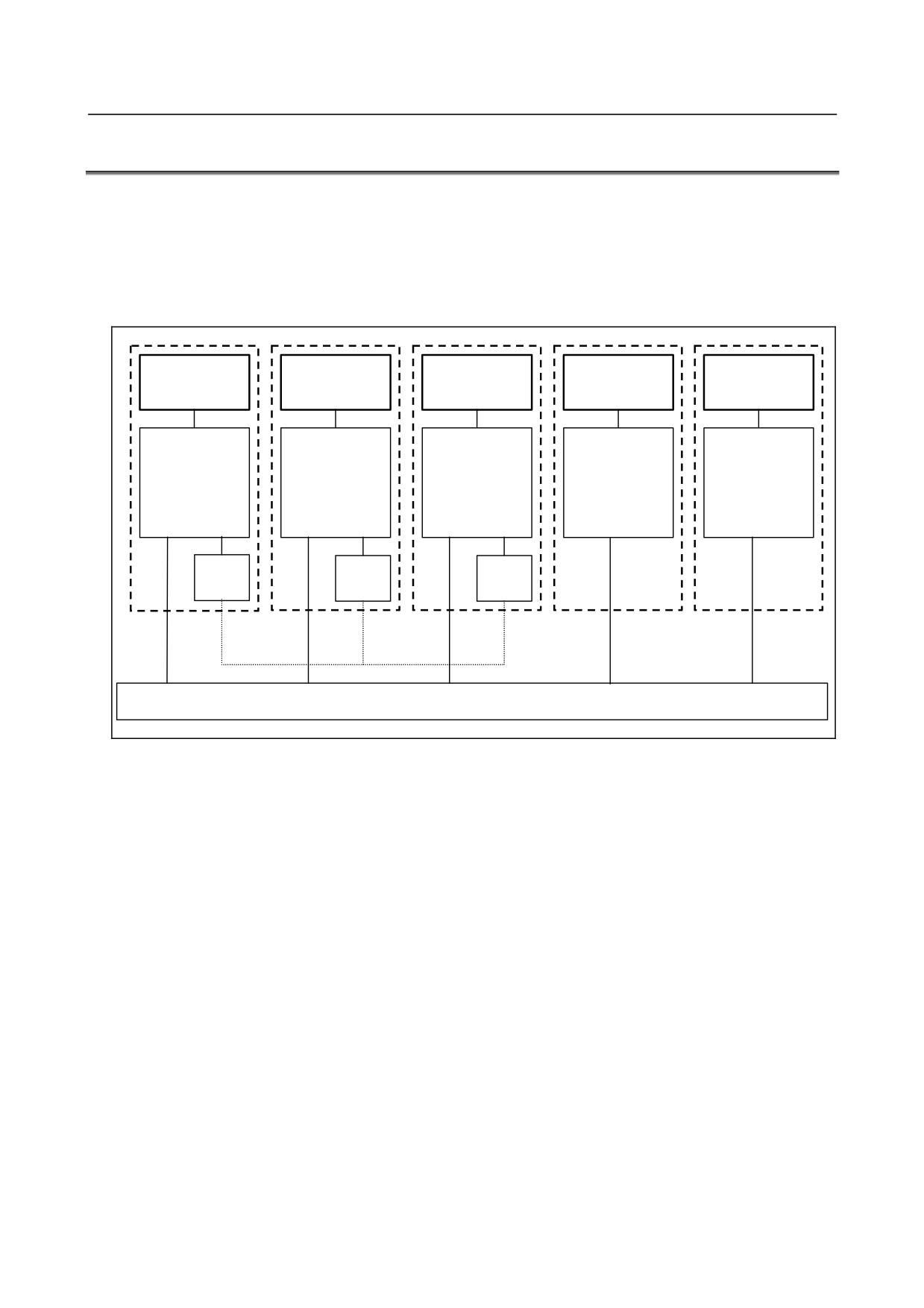
The multi-PMC function allows one PMC system to execute multiple sequence programs at the same
time.
PMC memory for each sequence program is basically independent, and the same PMC address can be
used for different purposes of the individual PMCs. Extra relays (E addresses) can be shared among
PMCs as shared memory. All PMCs can read from and write to this area, so the area can be used for the
interface between the PMCs. M,N addresses can be also used for the interface between the PMCs.
1st PMC
2nd PMC
3rd PMC
4th PMC
5th PMC
X0~, Y0~,
X0~, Y0~,
X0~, Y0~,
X0~, Y0~,
X0~, Y0~,
F0~, G0~,
F0~, G0~,
F0~, G0~,
F0~, G0~,
F0~, G0~,
R0~, A0~,
R0~, A0~,
R0~, A0~,
R0~, A0~,
R0~, A0~,
T0~, C0~,
T0~, C0~,
T0~, C0~,
T0~, C0~,
T0~, C0~,
K0~, D0~,
K0~, D0~,
K0~, D0~,
K0~, D0~,
K0~, D0~,
P1~, L1~
P1~, L1~
P1~, L1~
P1~, L1~
P1~, L1~
M0~,
M0~,
M0~,
N0~
N0~
N0~
Shared memory (E0 -)
Fig. 6.2 (a) PMC memory of multi-PMC function
A program for each PMC is saved as an independent file and can be edited, updated, and backed up
separately.
The CNC systems and the I/O Link channels to be controlled by PMCs can be changed by CNC
parameter setting. In a parameter-set configuration, one PMC may control all CNC systems, or each PMC
may control a different CNC system.
Fig. 6.2 (b) shows a configuration example.
- 336 -
B-64485EN/01
6.INTERFACE BETWEEN CNC AND PMC
CNC
PMC
Machine
1st PMC
Operator's
control group
panel for
machine
control, etc.
(1)
Peripheral
2nd PMC
equipment,
etc.
Loader
3rd PMC
Operator's
control group
panel for
loader, etc.
Fig. 6.2 (b) Multi-PMC function configuration example
If the Series 30i/31i/32i-A system is used to control more than one CNC path, some paths can be grouped
to share data within a group and to stop all the paths in the group if an alarm condition occurs in one of
the paths. The group is referred to as the machine group.
The system supports up to 3 machine groups. Each group has a separate emergency stop signal address.
A PMC is basically assigned to each machine group.
6.2.1
Execution Order and Execution Time Percentage
For the multi-PMC function, the order of PMC execution and execution time percentages of the PMCs
can be set with CNC parameters.
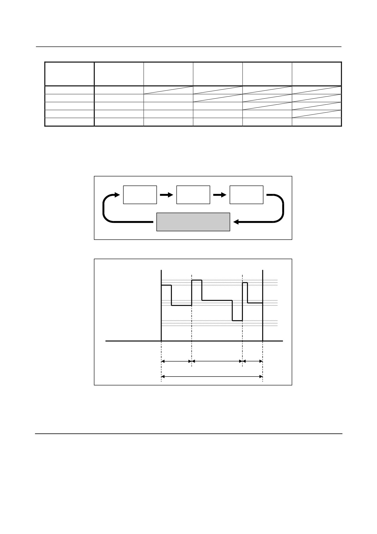
Execution order
If parameters related to the execution order are not set (0 is set), the order sequence is assumed by default:
1st PMC
2nd PMC
3rd PMC
4th PMC
5th PMC
Other processing such as
tracing
Fig. 6.2.1 (a) Default execution order of multiple PMCs
Execution time percentage
If parameters related to execution time percentages are not set (0 is set), the execution time percentages
(Table 6.2.1 (a)) are assumed by default:
- 337 -
6.INTERFACE BETWEEN CNC AND PMC
B-64485EN/01
Table 6.2.1 (a) Execution time percentages of multiple PMCs
The number of
PMC path of
PMC path of
PMC path of
PMC path of
PMC path of
PMC path
the 1st order of
the 2nd order
the 3rd order of
the 4th order of
the 5th order of
execution
of execution
execution
execution
execution
1 path
100%
2 paths
85%
15%
3 paths
75%
15%
10%
4 paths
70%
10%
10%
10%
5 paths
60%
10%
10%
10%
10%
An example of changing the execution order and execution time percentages by setting CNC parameters
is explained below. In the Figs. 6.2.1 (c) and 6.2.1 (d), sequence programs are executed in the order from
the third PMC to the first PMC to the second PMC with the execution time percentage of the third PMC
set to 30%, the percentage of the first PMC to 50%, and the percentage of the second PMC to 20%:
3rd PMC
1st PMC
2nd PMC
Other processing such as
tracing
Fig. 6.2.1 (b) Example of setting execution order of multiple PMCs
Level 1
Level 2
Level 3
3rd PMC
1st PMC
2nd PMC
(30%)
(50%)
(20%)
Ladder execution cycle (4 or 8 ms)
Fig. 6.2.1 (c) Example of setting execution time percentages of multiple PMCs
For details of parameter setting, see PMC PROGRAMMING MANUAL (B-64513EN).
6.2.2
Setting I/O Address for I/O Link i and I/O Link
The I/O addresses of I/O Link i can be set on the I/O configuration edit screen of the PMC.
For details of the I/O configuration display/editing screen, see PMC PROGRAMMING MANUAL
(B-64513EN).
The I/O addresses of I/O Link channels can be assigned with CNC parameters.
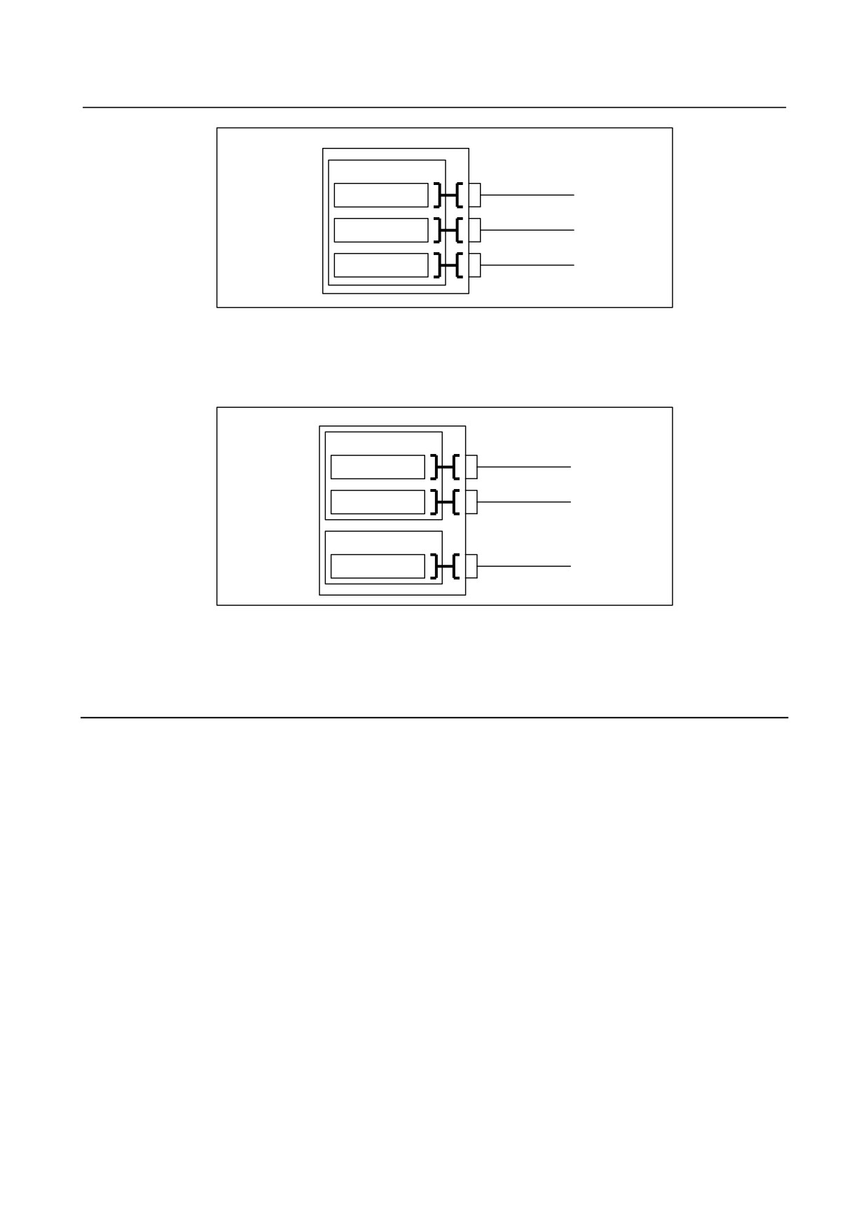
If these parameters are not set (0 is set), all channels are assigned to the first PMC by default as Fig. 6.2.2
(a):
- 338 -
B-64485EN/01
6.INTERFACE BETWEEN CNC AND PMC
1st PMC
Channel 1
X/Y0 to X/Y127
Channel 2
X/Y200 to X/Y327
Channel 3
X/Y400 to X/Y527
Fig. 6.2.2 (a) Default I/O addresses of I/O Link channels
In the example (Fig. 6.2.2 (b)), channel 1 is assigned to X/Y0 to X/Y127 of the first PMC, channel 2 is
assigned to X/Y200 to X/Y327 of the first PMC, channel 3 is assigned to X/Y0 to X/Y127 of the second
PMC:
1st PMC
Channel 1
X/Y0 to X/Y127
Channel 2
X/Y200 to X/Y327
2nd PMC
Channel 3
X/Y0 to X/Y127
Fig. 6.2.2 (b) Example of I/O address assignment for I/O Link channels
For details of parameter setting, see PMC PROGRAMMING MANUAL (B-64513EN).
6.2.3
Interface Between CNC and PMC
The PMC to control the interface between the CNC and PMC and PMC addresses (F/G addresses) can be
set with CNC parameters.
With these parameter settings, a desired interface control system can be built, in which the entire
CNC-PMC interface of the CNC may be controlled by a single PMC or the CNC-PMC interface may be
controlled by multiple PMCs.
For the CNC-PMC interface, a memory area consisting of 10 blocks, each of which is an addressable,
768-byte DI/DO area, is provided.
When viewed from the ladder program in each PMC, these addresses begin with 0.
If these parameters are not set (0 is set), the initial settings are assumed, where the F/G addresses of the
CNC equals the F/G addresses of the first PMC as Fig. 6.2.3 (a):
- 339 -

6.INTERFACE BETWEEN CNC AND PMC
B-64485EN/01
CNC
1st PMC
F/G0 to F/G767 of CNC
F/G0 to F/G767 of 1st PMC
F/G1000 to F/G1767 of CNC
F/G1000 to F/G1767 of 1st PMC
F/G2000 to F/G2767 of CNC
F/G2000 to F/G2767 of 1st PMC
F/G3000 to F/G3767 of CNC
F/G3000 to F/G3767 of 1st PMC
F/G4000 to F/G4767 of CNC
F/G4000 to F/G4767 of 1st PMC
F/G5000 to F/G5767 of CNC
F/G5000 to F/G5767 of 1st PMC
F/G6000 to F/G6767 of CNC
F/G6000 to F/G6767 of 1st PMC
F/G7000 to F/G7767 of CNC
F/G7000 to F/G7767 of 1st PMC
F/G8000 to F/G8767 of CNC
F/G8000 to F/G8767 of 1st PMC
F/G9000 to F/G9767 of CNC
F/G9000 to F/G9767 of 1st PMC
Fig. 6.2.3 (a) Initial settings for CNC-PMC interface
In the example (Fig. 6.2.3 (b)), F/G0 to F/G767 and F/G1000 to F/G1767 of the CNC are assigned to
F/G0 to F/G767 and F/G1000 to F/G1767 of the first PMC, and F/G2000 to F/G2767 of the CNC are
assigned to F/G0 to F/G767 of the second PMC:
CNC
1st PMC
F/G0 to F/G767 of CNC
F/G0 to F/G767 of 1st PMC
F/G1000 to F/G1767 of CNC
F/G1000 to F/G1767 of 1st PMC
F/G2000 to F/G2767 of CNC
2nd PMC
F/G0 to F/G767 of 2nd PMC
Fig. 6.2.3 (b) Setting example for CNC-PMC interface
6.2.4
Multi-Path PMC Interface
The multi-path PMC interface is the communication means between two PMC paths.
Generally, Each path of multi-path PMC system has individual PMC memory space except E address.
And, E address can be used to share data of multi-path PMC system. However, this method has a risk that
the memory is over written by other PMC path inappropriately.
When using this function, the input and output signals of each path become definitely. So, you can send
or receive the data on between two PMC paths safely.
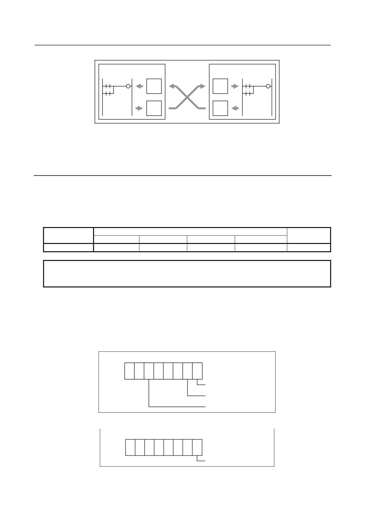
When you output data to N address at one of PMC paths, it can be referenced by M address in other PMC
path.
NOTE
This interface does not support the fourth or fifth PMC path.
- 340 -
B-64485EN/01
6.INTERFACE BETWEEN CNC AND PMC
Ex.) When using this function with 1st PMC and 2nd PMC :
1st PMC
2nd PMC
M
M
N
N
Moreover, signals of M address are synchronized during 1 scan of 2nd level program. Therefore, you can
reference the same signal status on the first step and the last step of level2 program, like as X and F
address.
6.2.5
System Relay Addresses (R9000, Z0)
The System Relay is used to control a sequence program by PMC System software. And, some addresses
such as 'Operation results of functional instructions' are used to condition of a sequence program.
The System Relay uses the following PMC address by each PMC Memory Type.
Table 6.2.5 (a) Address of System Relay
1st to 5th PMC
DCS PMC
PMC memory A
PMC memory B
PMC memory C
PMC memory D
System Relay
R9000 ~ R9499
R9000 ~ R9499
Z0 ~ Z499
Z0 ~ Z499
R9000 ~ R9499
NOTE
Ladder conversion from PMC memory A or B to PMC memory C or D requires
converting System Relay addresses.
Operation results of functional instructions
This area holds information necessary for individual ladder levels, such as the operation results of
functional instructions. This information is saved/restored when the task is switched.
(1) R9000, Z0 (operation output register for the ADDB, SUBB, MULB, DIVB, and COMPB functional
instructions)
7
6
5
4
3
2
1
0
R9000
Z0
The result is 0.
The result is negative.
The result has overflowed.
(2) R9000, Z0 (error output for the EXIN, WINDR, and WINDW functional instructions)
7
6
5
4
3
2
1
0
R9000
Z0
The result is erroneous.
- 341 -