FANUC Series 30i-MODEL B, 31i-MODEL B, 32i-MODEL B. MAINTENANCE MANUAL - page 11
3.REPLACING CONTROL UNIT MAINTENANCE PARTS
B-64485EN/01
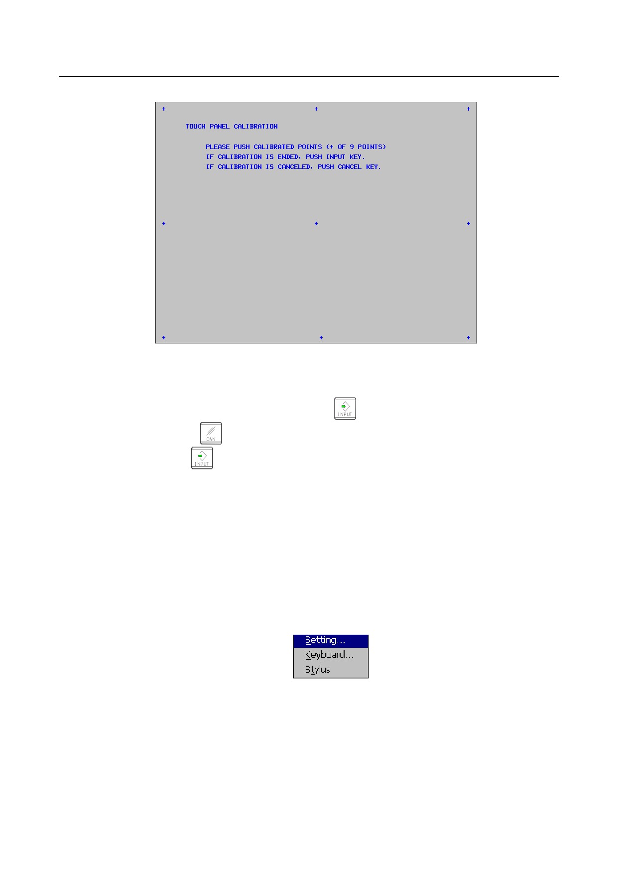
<5> Pressing the [TP CAL] soft key causes a full-screen touch panel calibration screen to appear.
<6> Click the 9 calibration points with a stylus pen. The marker of a normally clicked point changes
from "+" to "o". If you fail to click right on a "+" mark, the message "Your stylus pen is not right on
a "+" mark. Click again." appears.
<7> After clicking all 9 calibration points, clicking the
key completes calibration. To quit or retry
calibration, click the
key. The previous screen appears again. Before clicking 9 calibration
points, clicking the
key aborts calibration.
<8> When calibration ends normally, the message "Calibration ended" appears.
<9> After completing calibration, disable the touch panel calibration screen (by resetting the DCL
parameter (bit 5 of parameter No. 3113) to 0) to prevent operation mistake.
-
Touch panel calibration method (for LCD-moutend type control unit
(personalcomputer function with Windows® CE) and display unit for
stand-alone type control unit (personalcomputer function with Windows® CE))
Open the control panel and start the stylus.
Make calibration as directed in the window.
-
Touch panel calibration method (for display unit for automotive manufacture)
1.
Press the ALT-O key to display the following function menu.
2.
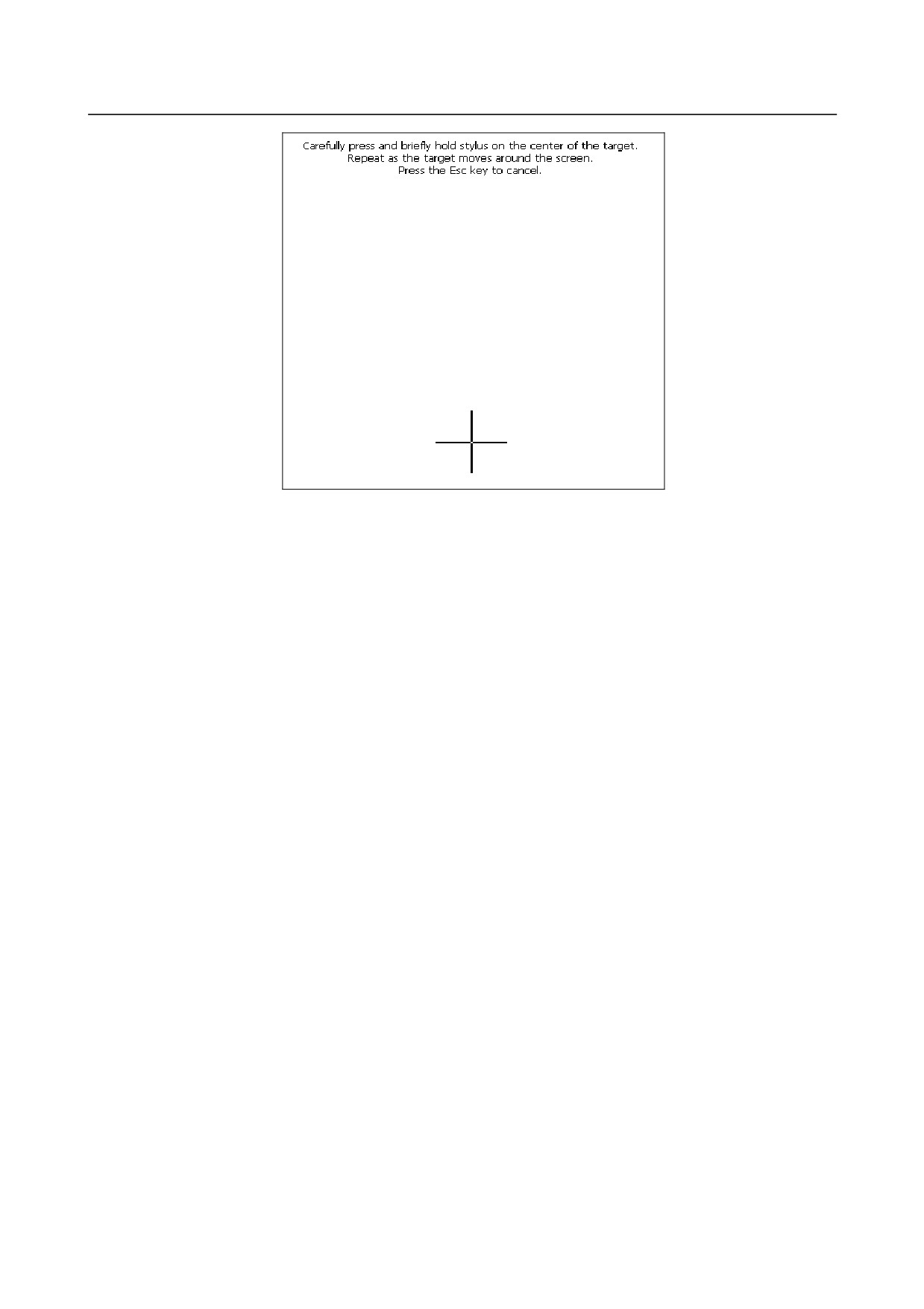
Select [Stylus] to display the calibration screen.
- 282 -
B-64485EN/01
3.REPLACING CONTROL UNIT MAINTENANCE PARTS
3.
When the crosshair cursor appears, press and hold the center of the cursor until it disappears (about
three seconds).
4.
When the cursor position moves, perform step 3 again. Repeat this process a total of five times.
5.
Press the RETURN key to close the calibration screen. To cancel the settings of the touch panel,
press the ESC key.
- 283 -
3.REPLACING CONTROL UNIT MAINTENANCE PARTS
B-64485EN/01
3.15 REPLACING THE BACKUP UNIT
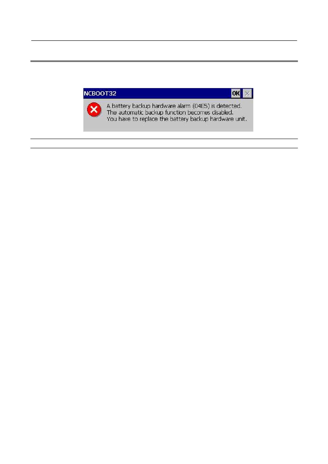
When "NCBOOT32- A battery backup hardware alarm(04E5)" appears on the screen of the
personalcomputer function with Windows® CE, replace the backup unit.
Procedure
<1> Turn off the CNC power, replace the backup unit, and turn on the power again.
<2> When the Windows screen appears, press the Ctrl key and Aux key of the MDI in sequence to
display the start menu, and start Windows Explorer.
<3> Execute "Storage Card¥Fanuc¥NCBOOT32.exe".
<4> When a pop-up menu appears at the lower left of the screen, select "Open".
<5> Check "Enable battery backup unit" to enable backup operation.
<6> Select "OK" to close NCBOOT32.
<7> Execute "Storage Card¥Fanuc¥NCBOOT32.exe".
<8> When a pop-up menu appears at the lower left of the screen, select "Save".
<9> Turn off the CNC power and back on again. Confirm that a backup operates normally and no alarm
appears.
- 284 -
B-64485EN/01
4.MAINTENANCE OF THE OTHER UNITS
4 MAINTENANCE OF THE OTHER UNITS
4.1
CAUTIONS COMMON TO THE OTHER UNITS
-
Replacing fuses
WARNING
Before replacement of a blown fuse, the cause of the blown fuse must be
corrected. So, fuse replacement work must be done only by a person who is
trained in the related maintenance and safety requirements. When opening the
cabinet and replacing a fuse inside, be careful not to touch the high-voltage
circuits (marked with
and fitted with an insulating cover). Touching the
uncovered high-voltage circuits presents an extremely dangerous electric shock
hazard.
See the descriptions of each unit in this chapter for the locations of their fuses.
See also Appendix B, “LISTS OF UNITS, PRINTED CIRCUIT BOARDS, AND CONSUMABLES” for
the specifications of the fuses for each unit.
4.2
UNITS SUPPORTING I/O Link i
4.2.1
Items Common to Units Supporting I/O Link i
- Meanings of LED displays on units supporting I/O Link i
The standard I/O Link i incorporates three LEDs, “LINK” (green), “ALM” (red), and “FUSE” (red) for
each unit separately. The information represented using each LED is as follows:
LED「LINK」(green)
Indicates the status of communication by the unit of interest.
LED「ALM」(red) Indicates that an alarm has been issued in the unit of interest.
LED「FUSE」(red)
Indicates where there is a blown fuse in the unit of interest.
See Section 10.26 for descriptions of the on/off states of the LEDs and their meanings.
- Status Alarm
Some I/O units have a function which detects unit errors including DO alarms (ground faults) and DO
common voltage errors. If these units detect an error described above, how detected information is
transferred to the master differs between the I/O Link and I/O Link i.
With the I/O Link, detected information is transferred to the master as DI signals. For this reason, to allow
the master to reference the detected information, as many signals as required for the detected information
must be assigned to X addresses. As many signals as required for the detected information are assumed as
the number of DI signals used by the group and channel.
With the I/O Link i, detected information is called a status alarm, and the CNC is notified of the status
alarm separate from DI signals. For this reason, it is not necessary to assign the information to X
addresses. If an error occurs, the information is output to the system relay (R or Z) area. The information
only for one group per channel is output to the system relay area. Only the information for the first group
in which a status alarm is detected is output.
Given below are the examples of system relay areas where a status alarm is issued.
See the descriptions of each unit in this section for the correspondence between the slot number and alarm
information number for them.
- 285 -
4.MAINTENANCE OF THE OTHER UNITS
B-64485EN/01
For details of the system relay area, refer to the FANUC Series
30i/31i/32i-MODEL B PMC
Programming Manual (B-64513EN).
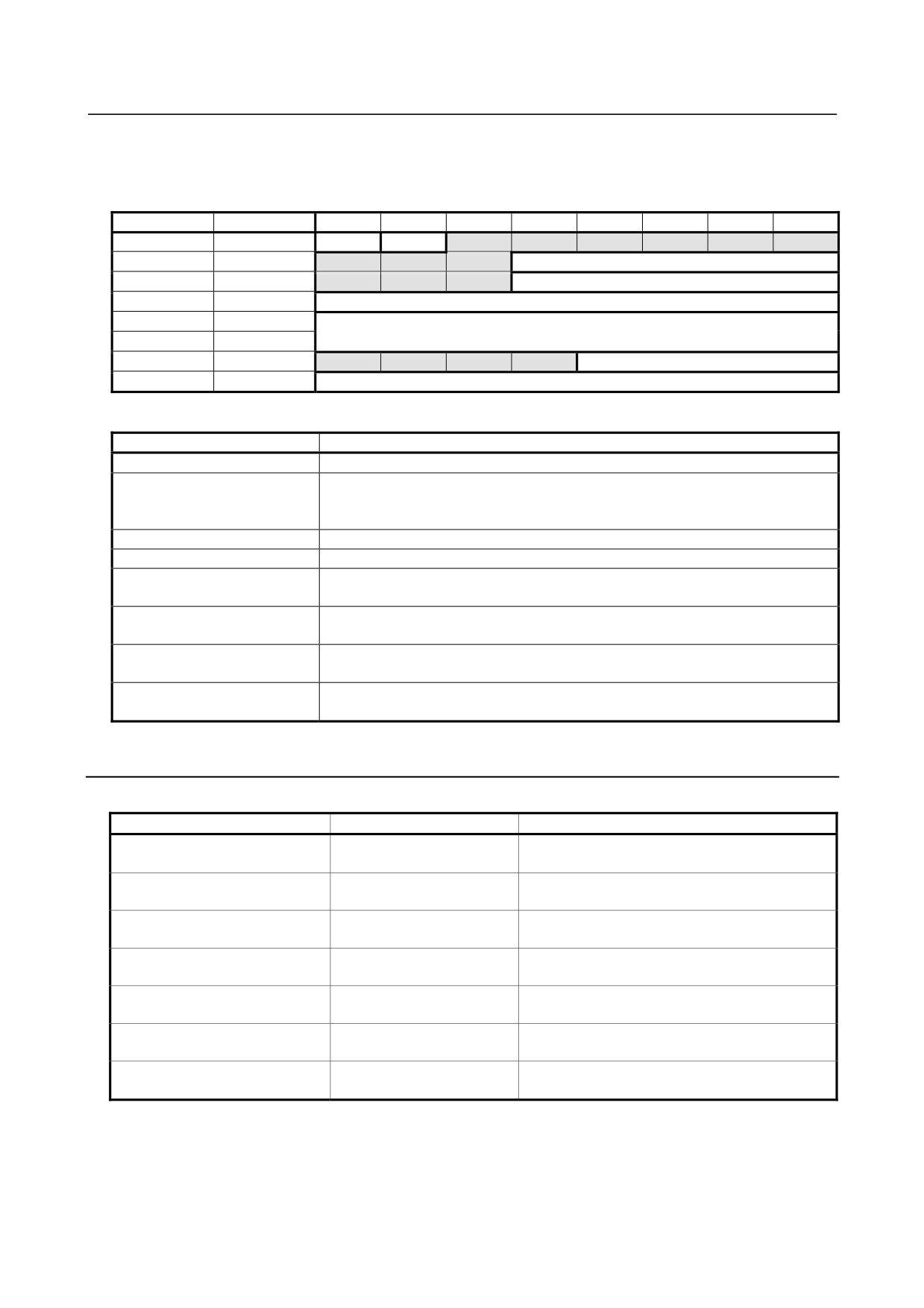
[Reference] System relay area related to a status alarm
Channel 1
Channel 2
7
6
5
4
3
2
1
0
R9268(Z268)
R9276(Z276)
Status
Type
R9269(Z269)
R9277(Z277)
Group number
R9270(Z270)
R9278(Z278)
Slot number
R9271(Z271)
R9279(Z279)
Alarm information number
R9272(Z272)
R9280(Z280)
Y address number
R9273(Z273)
R9281(Z281)
R9274(Z274)
R9282(Z282)
PMC path
R9275(Z275)
R9283(Z283)
Alarm data
[Reference] Simple description of signals
Name
Description
Status
Indicates that a status alarm occurs when this signal is set to 1.
Type
Indicates the type of status alarm.
0: DO alarm (such as a ground fault), 1: Other than a DO alarm (such as a DO
common voltage error)
Group number
Outputs a group number (0 to 23).
Slot number
Outputs a numeric value 0 to 31, which indicates slot number 1 to 32.
Alarm information number
Outputs the position of the alarm information corresponding to the alarm which
occurs (byte position in the slot).
Y address number
Outputs the Y address number of the relevant DO signal. Valid when the PMC
path value is other than 0.
PMC path
Outputs the PMC path at the Y address assigned to the relevant DO signal.
Outputs 0 if no address is assigned to the DO signal.
Alarm data
Outputs information on the alarm which occurs. Outputs 1 to the bit corresponding
to the alarm which occurs.
4.2.2
I/O Module for Connector Panel [Supporting I/O Link i]
-
Specification
Name
Ordering specifications
Specification
I/O module for connector panel
A03B-0824-C001
DI/DO : 24/16
(basic module)
I/O module for connector panel
DI/DO : 24/16
A03B-0824-C002
(extension module A)
With MPG interface
I/O module for connector panel
DI/DO : 24/16
A03B-0824-C003
(extension module B)
Without MPG interface
I/O module for connector panel
DO : 16
A03B-0824-C004
(extension module C)
2A output module
I/O module for connector panel
A03B-0824-C005
Analog input module
(extension module D)
1A
Fuse (spare parts)
A03B-0815-K002
(For basic module)
20 mm long
Flat cable between modules
A03B-0815-K100
Suitable for a module interval of 32 mm
- 286 -
B-64485EN/01
4.MAINTENANCE OF THE OTHER UNITS
-
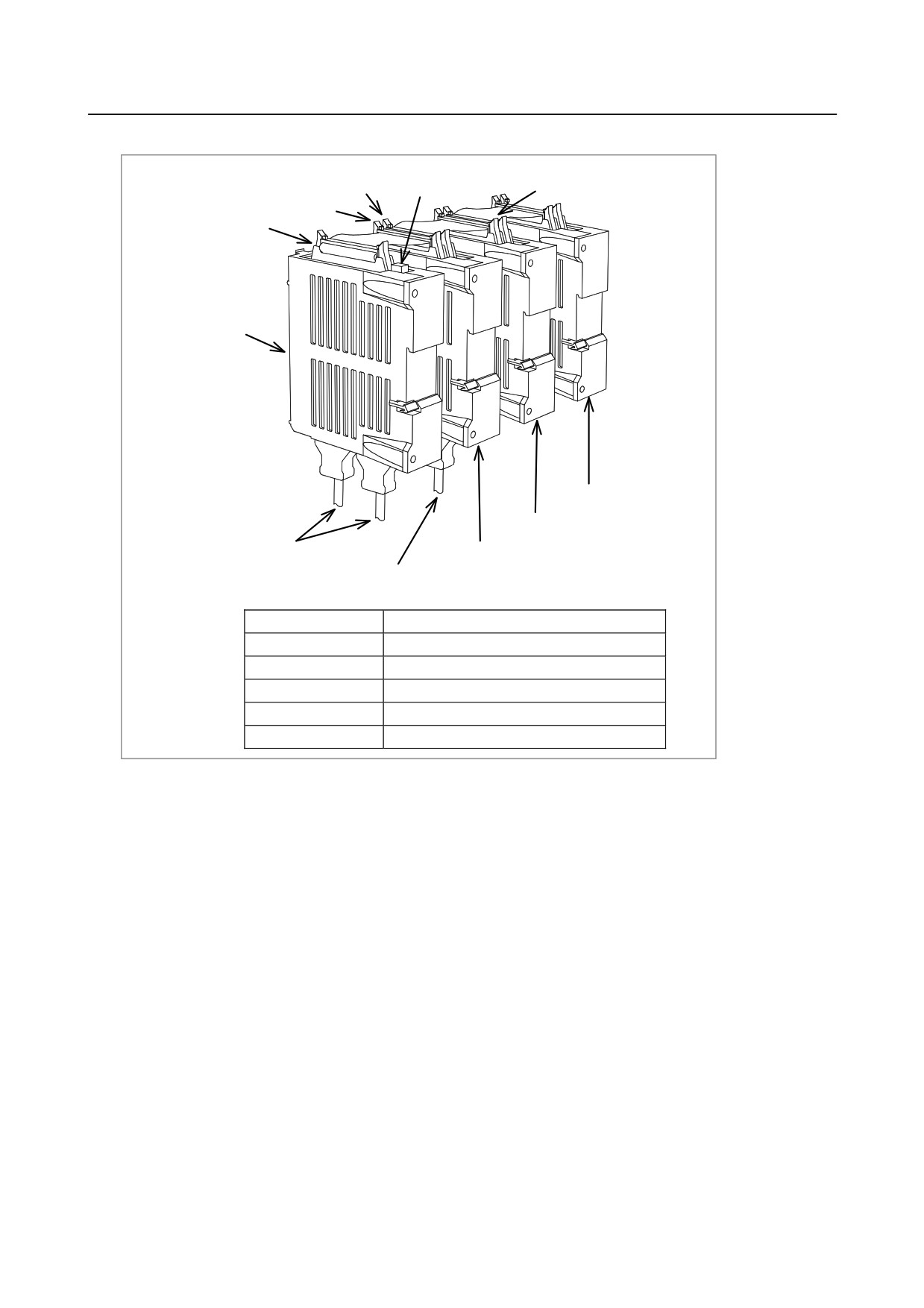
Connector and fuse locations
CA137
Fuse
Flat cable between modules
CA138
CA137
Basic module
JD1A
JA3
Extension module 3
JD1B
Extension module 2
Cable for I/O Link
Extension module 1
Cable for manual pulse generator
(with manual pulse generator interface)
Connector number
Use
JD1A
Second I/O Link i stage
JD1B
First I/O Link i stage
JA3
Manual pulse generator
CA137
Later stage in inter-module connection
CA138
Early stage in inter-module connection
- 287 -
4.MAINTENANCE OF THE OTHER UNITS
B-64485EN/01
-
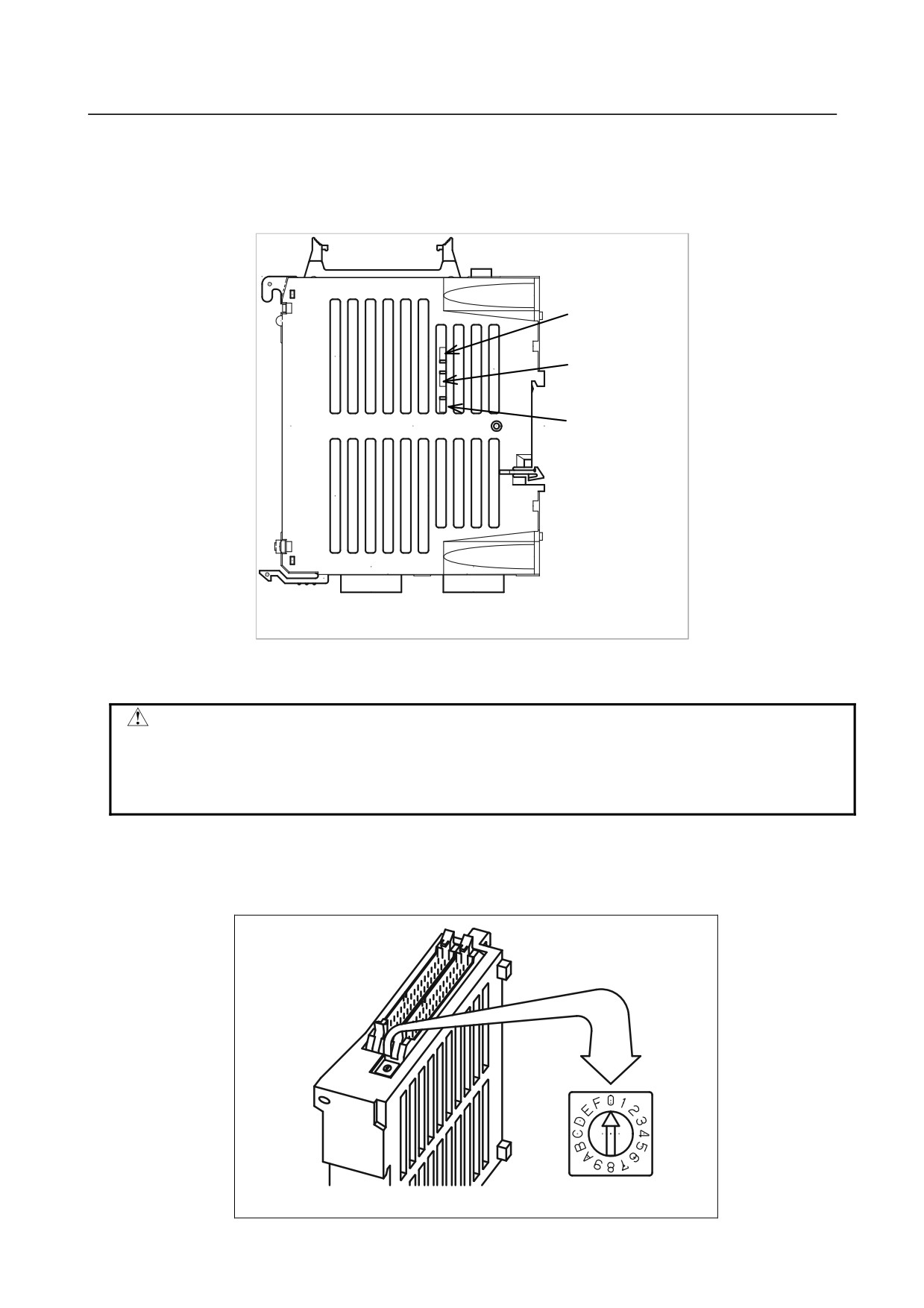
LED
The basic module incorporates a green LED, “LINK”, and two red LEDs, “ALM” and “FUSE”.
See Subsection 4.2.1 for descriptions of the correspondence between the on/off state of each LED and the
status of the I/O module for connector panel.
ALM (red)
LINK (green)
FUSE (red)
JD1A
JD1B
-
Rotary switch
CAUTION
The rotary switch on each extension module is used to connect them by skipping
other extension modules (slots).
When replacing extension modules, set the rotary switch on a replacing module in
the same manner as for the replaced module.
Method of setting (control and setting method)
A control (rotary switch) is provided on the location shown below of each expansion module. When
changing the setting, turn the rotary switch with a flat-blade screwdriver with a tip diameter of about 2.5
mm.
- 288 -
B-64485EN/01
4.MAINTENANCE OF THE OTHER UNITS
-
Correspondence between slot numbers and intra-slot byte addresses
The table below lists the slot number and intra-slot byte address for this module.
Slot number
Intra-slot byte address
DO address
Location
1
0
Yn1
Basic module
1
1
Yn1+1
Basic module
2
0
Yn2
Extension module 1
2
1
Yn2+1
Extension module 1
3
0
Yn3
Extension module 2
3
1
Yn3+1
Extension module 2
4
0
Yn4
Extension module 3
4
1
Yn4+1
Extension module 3
4.2.3
I/O Module for Operator’s Panel (Supporting Matrix Input)
[Supporting I/O Link i]
-
Specification
Name
Specification
Remark
I/O module for operator’s panel
A03B-0824-K200
Fuse (spare parts)
A03B-0815-K001
1A
-
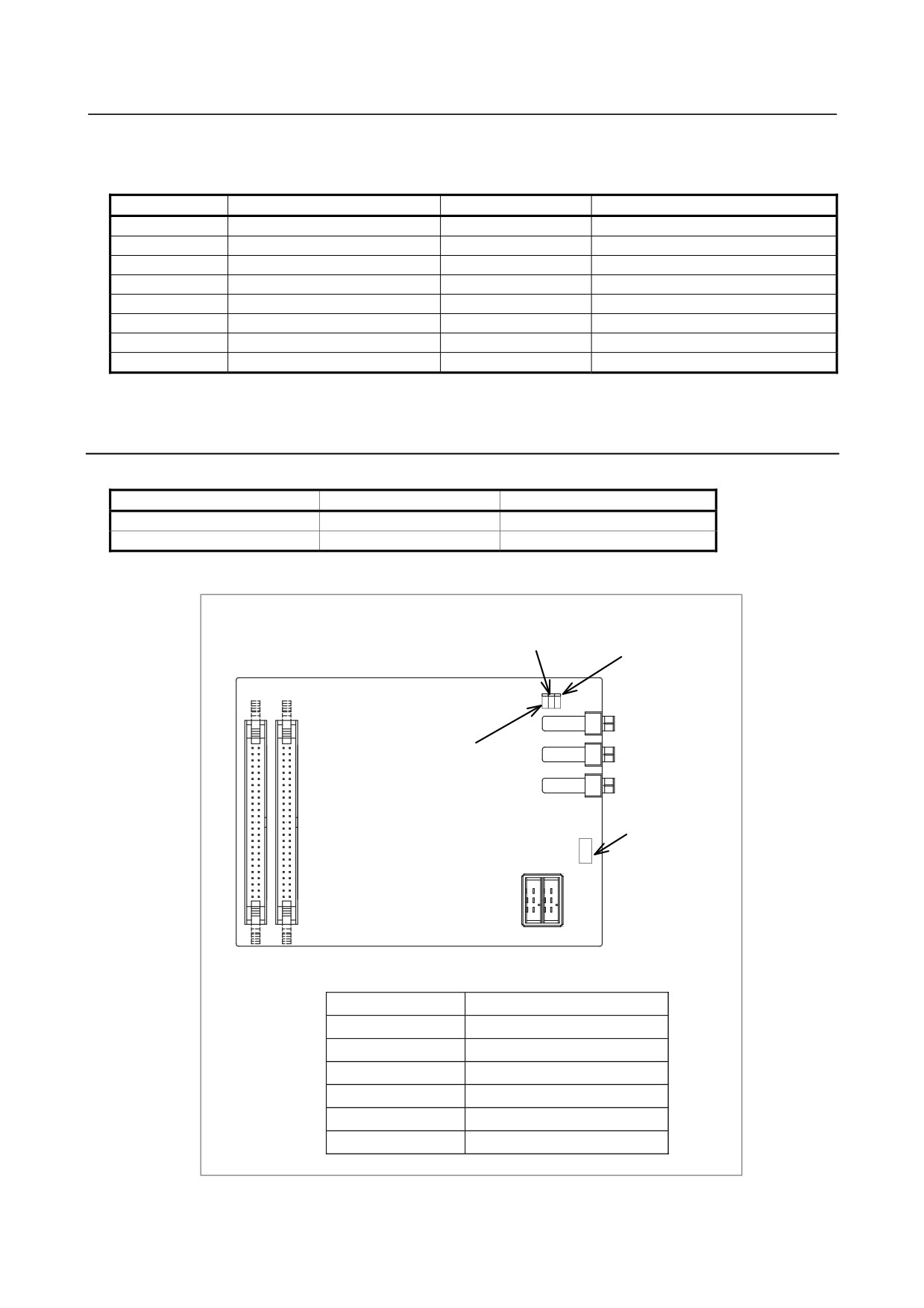
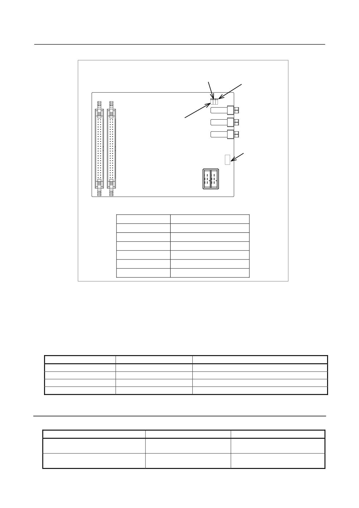
Connector, LED, and fuse locations
LINK LED (green)
FUSE LED (red)
JD1A
ALM LED (red)
JD1B
JA3
Fuse
CE53 CE54
CPD1
Connector number
Use
JD1A
Second I/O Link i stage
JD1B
First I/O Link i stage
JA3
Manual pulse generator
CPD1
24VDC input/output
CE53
DI/DO connector 1
CE54
DI/DO connector 2
- 289 -
4.MAINTENANCE OF THE OTHER UNITS
B-64485EN/01
-
LED
The I/O module for operator’s panel incorporates a green LED, “LINK”, and two red LEDs, “ALM” and
“FUSE” in above figure.
See Subsection 4.2.1 for descriptions of the correspondence between the on/off state of each LED and the
status of the I/O module for operator’s panel.
-
Correspondence between slot numbers and intra-slot byte addresses
The table below lists the slot number and intra-slot byte address for this module.
With this module, DO alarms (such as ground fault) are detected for each byte separately.
Information output to the system relay area
Description
Slot number
Alarm information number
Alarm data bit 0 data
1
0
1
Yn1 error
1
1
1
Yn1+1 error
1
2
1
Yn1+2 error
1
3
1
Yn1+3 error
1
4
1
Yn1+4 error
1
5
1
Yn1+5 error
1
6
1
Yn1+6 error
4.2.4
Connection of I/O Module for Operator's Panel and I/O
Module for Power Magnetics Cabinet [Supporting I/O Link i]
・ Specification
Item
Ordering specifications
Remarks
DI : 48 points
I/O module for operator’s panel
A03B-0824-K202
DO : 32 points
(with MPG interface)
With MPG interface
DI : 48 points
I/O module for power magnetics cabinet
A03B-0824-K203
DO : 32 points
(without MPG interface)
Without MPG interface
Fuse (spare parts)
A03B-0815-K001
1A
- 290 -
B-64485EN/01
4.MAINTENANCE OF THE OTHER UNITS
-
Connector, LED, and fuse locations
LINK LED (green)
FUSE LED (red)
JD1A
ALM LED (red)
JD1B
JA3
Fuse
CE56 CE57
CPD1
Connector number
Use
JD1A
Second I/O Link i stage
JD1B
First I/O Link i stage
JA3
Manual pulse generator
CPD1
24VDC input/output
CE56
DI/D connector 1
CE57
DI/DO connector 2
-
LED
The I/O module for operator’s panel incorporates a green LED, “LINK”, and two red LEDs, “ALM” and
“FUSE” in above figure.
See Subsection 4.2.1 for descriptions of the correspondence between the on/off state of each LED and the
status of the I/O module for operator’s panel.
-
Correspondence between slot numbers and intra-slot byte addresses
The table below lists the slot number and intra-slot byte address for this module.
Slot number
Alarm information number
Address of the DO driver which detects an error
1
0
Yn1
1
1
Yn1+1
1
2
Yn1+2
1
3
Yn1+3
4.2.5
I/O Module Type-2 for Connector Panel [Supporting I/O Link i]
-
Specification
Item
Ordering specifications
Specification
I/O module type-2 for connector panel
A03B-0824-C040
DI/DO=48/32
(basic module B1)
With MPG interface
I/O module type-2 for connector panel
A03B-0824-C041
DI/DO=48/32
(basic module B2)
Without MPG interface
- 291 -
4.MAINTENANCE OF THE OTHER UNITS
B-64485EN/01
Item
Ordering specifications
Specification
I/O module type-2 for connector panel
A03B-0824-C042
DI/DO=48/32
(extension module E1)
Fuse (spare parts)
A03B-0815-K002
1 A (for basic module)
Inter-module flat cable
A03B-0815-K102
Cable length: 35 mm
Module interval: 5 mm
-
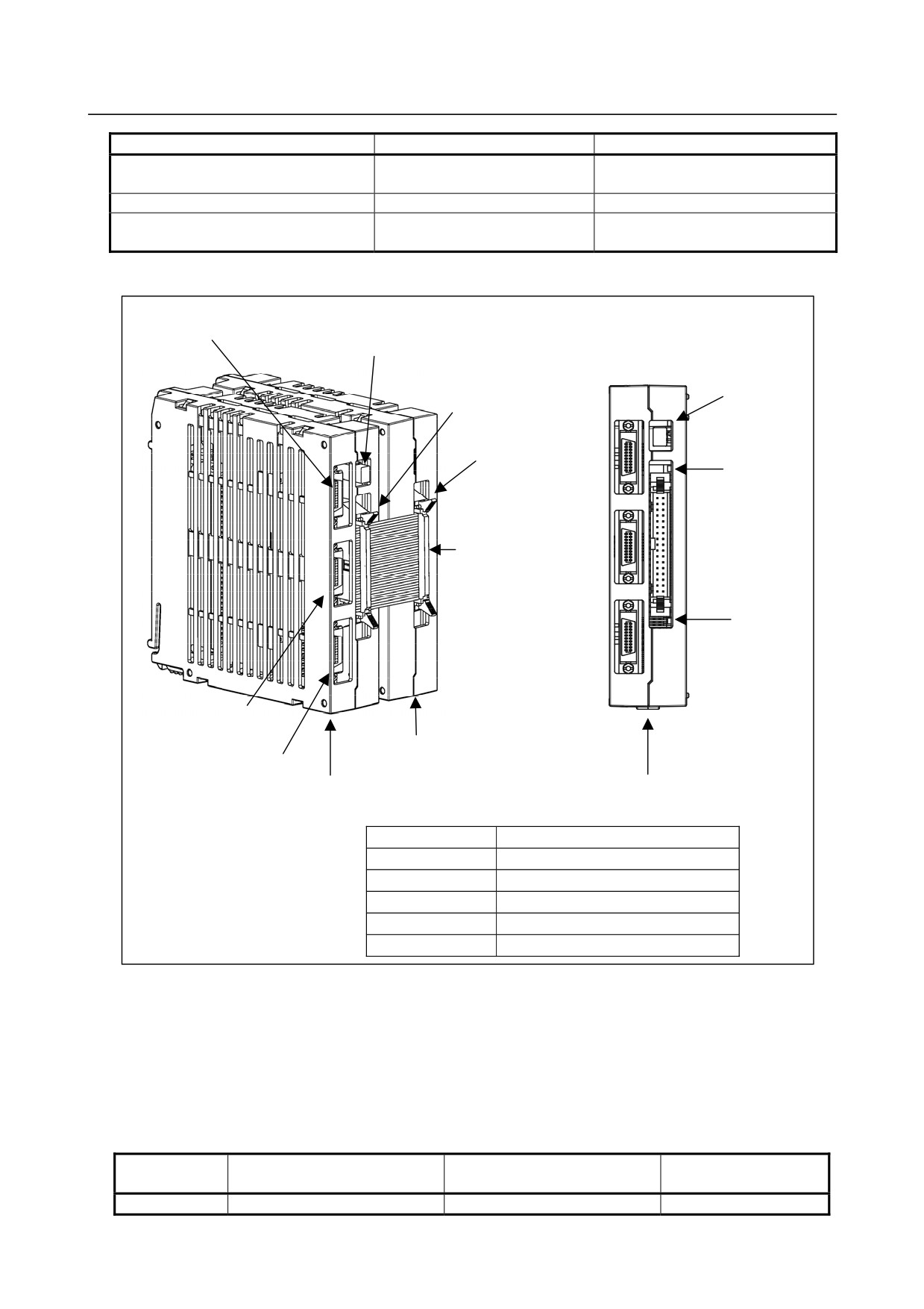
Connector, LED, and fuse locations
JD1B
Fuse
FUSE LED
CA140
(red)
CA141
LINK LED
(green)
Flat cable for
module connection
ALM LED
(red)
JD1A
Extension module
JA3
Basic module
Basic module
Connector number
Use
JD1A
Second I/O Link i stage
JD1B
First I/O Link i stage
JA3
Manual pulse generator
CA140
Inter-module connection (basic)
CA141
Inter-module connection (extension)
-
LED
The basic module incorporates a green LED, “LINK”, and two red LEDs, “ALM” and “FUSE”.
See Subsection 4.2.1 for descriptions of the correspondence between the on/off state of each LED and the
status of the I/O module type-2 for connector panel.
-
Correspondence between slot numbers and intra-slot byte addresses
The table below lists the slot number and intra-slot byte address for this module.
Address of the DO driver
Slot number
Alarm information number
Location
which detects an error
1
0
Yn1
Basic module
- 292 -
B-64485EN/01
4.MAINTENANCE OF THE OTHER UNITS
Address of the DO driver
Slot number
Alarm information number
Location
which detects an error
1
1
Yn1+1
Basic module
1
2
Yn1+2
Basic module
1
3
Yn1+3
Basic module
2
0
Yn2
Extension module
2
1
Yn2+1
Extension module
2
2
Yn2+2
Extension module
2
3
Yn2+3
Extension module
4.2.6
Terminal Type I/O Module [Supporting I/O Link i]
-
Specification
Item
Ordering specifications
Specification
Basic module
A03B-0823-C011
DI/DO: 24/16
DI/DO : 24/16
Extension module A
A03B-0823-C012
With MPG interface
DI/DO : 24/16
Extension module B
A03B-0823-C013
Without MPG interface
DO : 16
Extension module C
A03B-0823-C014
2-A output module
Extension module D
A03B-0823-C015
Analog input module
Extension module E
A03B-0823-C016
Analog output module
Fuse (spare parts)
A03B-0823-K001
2A (for basic module)
Spare terminal block set
Cable-side terminal block set (including each
(for basic module and extension
A03B-0823-K020
of T1 through T4)
module A/B)
Spare terminal block set
Cable-side terminal block set (including each
A03B-0823-K011
(for extension module C)
of T1 and T2)
Spare terminal block set
Cable-side terminal block set (including each
A03B-0823-K012
(for extension module D)
of T1 and T2)
Spare terminal block set
Cable-side terminal block set (including each
A03B-0823-K013
(for extension module E)
of T1 and T2)
Cable length: 100 mm, 52 pins
Inter-module cable A
A03B-0823-K100
Used for extension module connection
CAUTION
The spare terminal board set is a replacement set for a cable-side terminal board
supplied with the main unit.
- 293 -
4.MAINTENANCE OF THE OTHER UNITS
B-64485EN/01
-
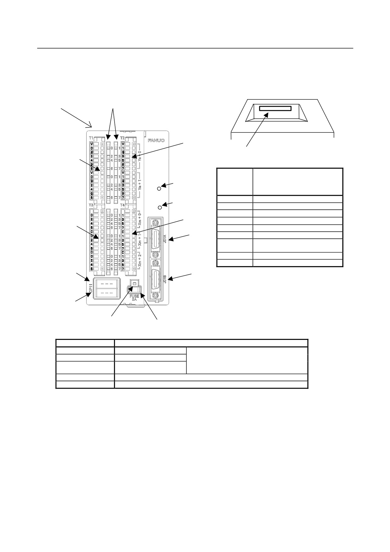
Locations of connectors, fuses, LEDs, etc.
Basic module A03B-0823-C011
As seen from A in figure at left.
A (See figure at right.) DI/DO status display LED
T2
CA105
T1
Communication
status display
Connector /
LED
terminal
Use
board
LINK
number
Alarm status
CP11A
24-VDC power supply input
display LED
ALM
CP11B
24-VDC power supply output
S
S
JD1A
Second I/O Link i stage
T4
JD1B
First I/O Link i stage
T3
CA105
Extension module connection
JD1A
T1
DO terminal board with aqua label
T2
DO terminal board with lime green
label
T3
DI terminal board with yellow label
T4
DI terminal board with pink label
CP11A
JD1B
FUSE
CP11B
Blown fuse display LED
Fuse, 2 A
Meanings of LED displays
LED
Meaning
LINK
Status of communication
See Subsection 4.2.1 for the
ALM
Occurrence of alarm
correspondence between the on/off state of
FUSE
Blown fuse
each LED and the status of the terminal
board type I/O module.
DO 0 to 7 (2 bytes)
Light when DO is ON.
DI 0 to 7 (3 bytes)
Light when DIO is ON.
- 294 -
B-64485EN/01
4.MAINTENANCE OF THE OTHER UNITS
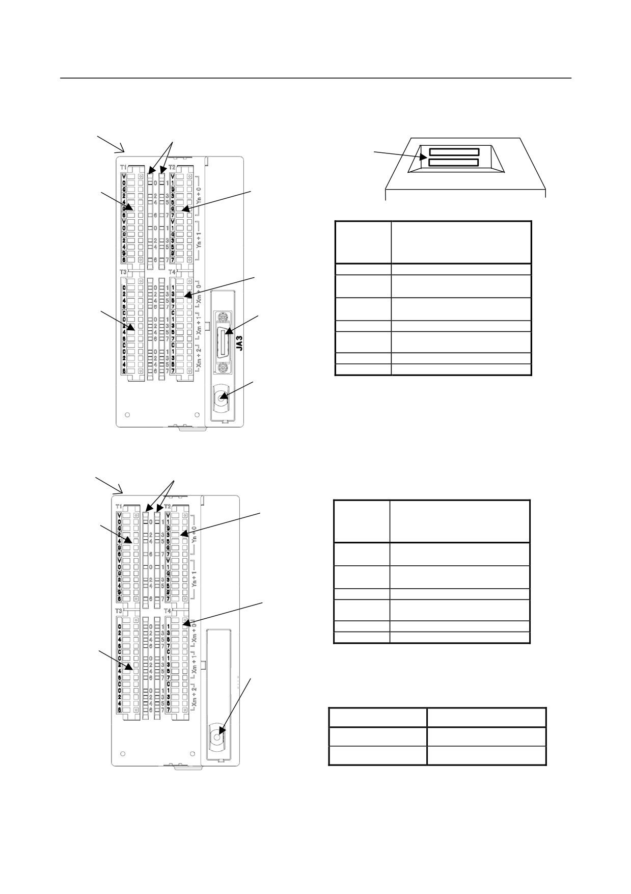
Extension module A A03B-0823-C012
As seen from A in figure at left.
A (See figure at right.)
(Common to A03B-0823-C012 and A03B-0823-C013)
DI/DO status display LED
CA105
CA106
T1
T2
Connector /
terminal
Use
board
number
JA3
MPG interface
T4
S
S
CA105
Extension module connection
(to next-stage extension module)
CA106
Extension module connection
T3
JA3
(to previous-stage basic module)
T1
DO terminal board with aqua label
T2
DO terminal board with lime green
label
T3
DI terminal board with yellow label
T4
DI terminal board with pink label
Rotary switch
Extension module B A03B-0823-C013
A (See figure at right.) DI/DO status display LED
Connector /
T2
terminal
T1
Use
board
number
CA105
Extension module connection
(to next-stage extension module)
CA106
Extension module connection
(to previous-stage basic module)
T1
DO terminal board with aqua label
T4
T2
DO terminal board with lime green
label
S
S
T3
DI terminal board with yellow label
T4
DI terminal board with pink label
T3
Rotary switch
Meanings of LED displays
(Common to A03B-0823-C012 and A03B-0823-C013)
LED
Meaning
DO 0 to 7 (2 bytes)
Light when DO is ON.
DI 0 to 7 (3 bytes)
Light when DIO is ON.
- 295 -
4.MAINTENANCE OF THE OTHER UNITS
B-64485EN/01
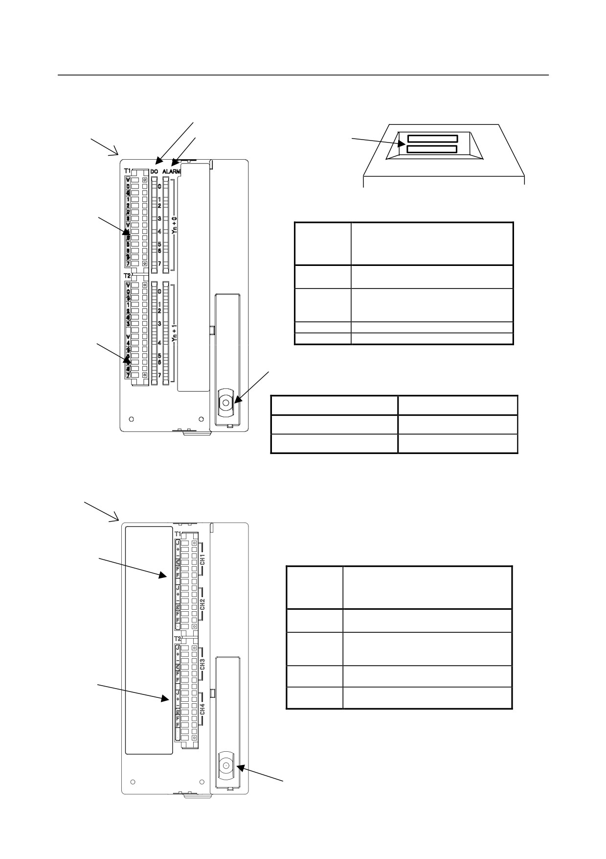
As seen from A in figure at left. (Common to
Extension module C A03B-0823-C014
A03B-0823-C014 and A03B-0823-C015)
DO status display LED (green)
A (See figure at right.)
DO alarm display LED (red)
CA105
CA106
T1
Connector /
terminal
Use
board
number
CA105
Extension module connection
(to next-stage expansion module)
CA106
Extension module connection
(to previous-stage basic or extension
module)
T1
DO terminal board with aqua label
T2
DO terminal board with lime green label
T2
Rotary switch
Meanings of LED displays
LED
Meaning
DO 0 to 7 (2 bytes)
Light when DO is ON.
ALARM 0 to 7 (2 bytes)
Light to indicate an alarm.
Extension module D A03B-0823-C015
A (See figure at right.)
T1
Connector /
terminal
Use
board
number
CA105
Extension module connection
(to next-stage expansion module)
CA106
Extension module connection
(to previous-stage basic or extension
module)
T1
Analog input CH1 and CH2 terminal board
T2
with yellow label
T2
Analog input CH3 and CH4 terminal board
with pink label
Rotary switch
- 296 -
B-64485EN/01
4.MAINTENANCE OF THE OTHER UNITS
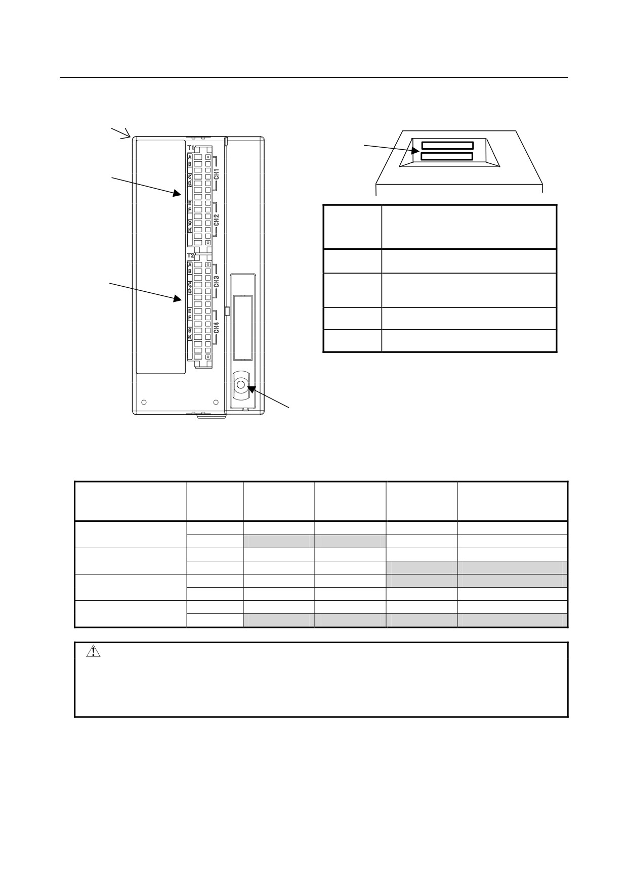
Extension module E A03B-0823-C016
As seen from A in figure at left.
A (See figure at right.)
CA105
CA106
T1
Connector /
terminal
Use
board
number
CA105
Extension module connection
(to next-stage expansion module)
CA106
Extension module connection
T2
(to previous-stage basic or extension
module)
T1
Analog input CH1 and CH2 terminal board
with lime green label
T2
Analog input CH3 and CH4 terminal board
with sky blue label
Rotary switch
States when the protection function is activated in extension module C
The following table lists the DO output and alarm data states when a DO error occurs in extension
module C and the protection function is activated.
DO state
PMC
Module DO
DO alarm
State
indication
Alarm data
output
output
LED (red)
LED (green)
0
OFF
Turned off
Turned off
0
Normal operation
1
ON
Turned on
Turned off
0
Overheat protection
0
OFF
Turned off
Turned off
0
function operation
1
OFF
Turned off
Turned on
1
Over voltage protection
0
OFF
Turned off
Turned on
1
function operation
1
OFF
Turned off
Turned off
0
0
OFF
Turned off
Turned off
0
Disconnection detection
1
ON
Turned on
Turned on
1
CAUTION
1 If the overheat protection function or over voltage protection function among the
protection functions above is activated, the DO bit is kept OFF until the cause is
eliminated. When the cause is eliminated, the DO bit is set to ON without
restarting the system.
- 297 -
4.MAINTENANCE OF THE OTHER UNITS
B-64485EN/01
CAUTION
2 Disconnection detection is performed by monitoring, with an output element in the
module, the current flowing through a load when DO output is ON. When the
detected current value is about 100 mA or less, disconnection detection is
assumed. So, when a device (such as an LED) with a small load current is
connected, the DO alarm state results, assuming disconnection detection. Unlike
the other protection functions, however, this function does not turn off DO output.
If a connection is reactivated after the state of disconnection is once set,
disconnection detection is canceled without restarting the system.
-
Rotary switch
CAUTION
When replacing extension modules, set the rotary switch on a replacing module in
the same manner as for the replaced module.
Re-setting the rotary switch on each extension module can be used to connect them by skipping other
modules. For details, see descriptions of the rotary switch in Subsection 4.2.2, “I/O module for connector
panel”.
-
Correspondence between slot numbers and intra-slot byte addresses
The table below lists the slot number and intra-slot byte address for this module.
Slot number
Intra-slot byte address
DO address
Location
1
0
Yn1
Basic module
1
1
Yn1+1
Basic module
2
0
Yn2
Extension module 1
2
1
Yn2+1
Extension module 1
3
0
Yn3
Extension module 2
3
1
Yn3+1
Extension module 2
4
0
Yn4
Extension module 3
4
1
Yn4+1
Extension module 3
4.2.7
I/O Link Connection Unit [Supporting I/O Link i]
Specification
Name
Specification
I/O Link connection unit
A02B-0333-C250
Fuse 1A (spare parts, 1 piece)
A03B-0815-K001
- 298 -
B-64485EN/01
4.MAINTENANCE OF THE OTHER UNITS
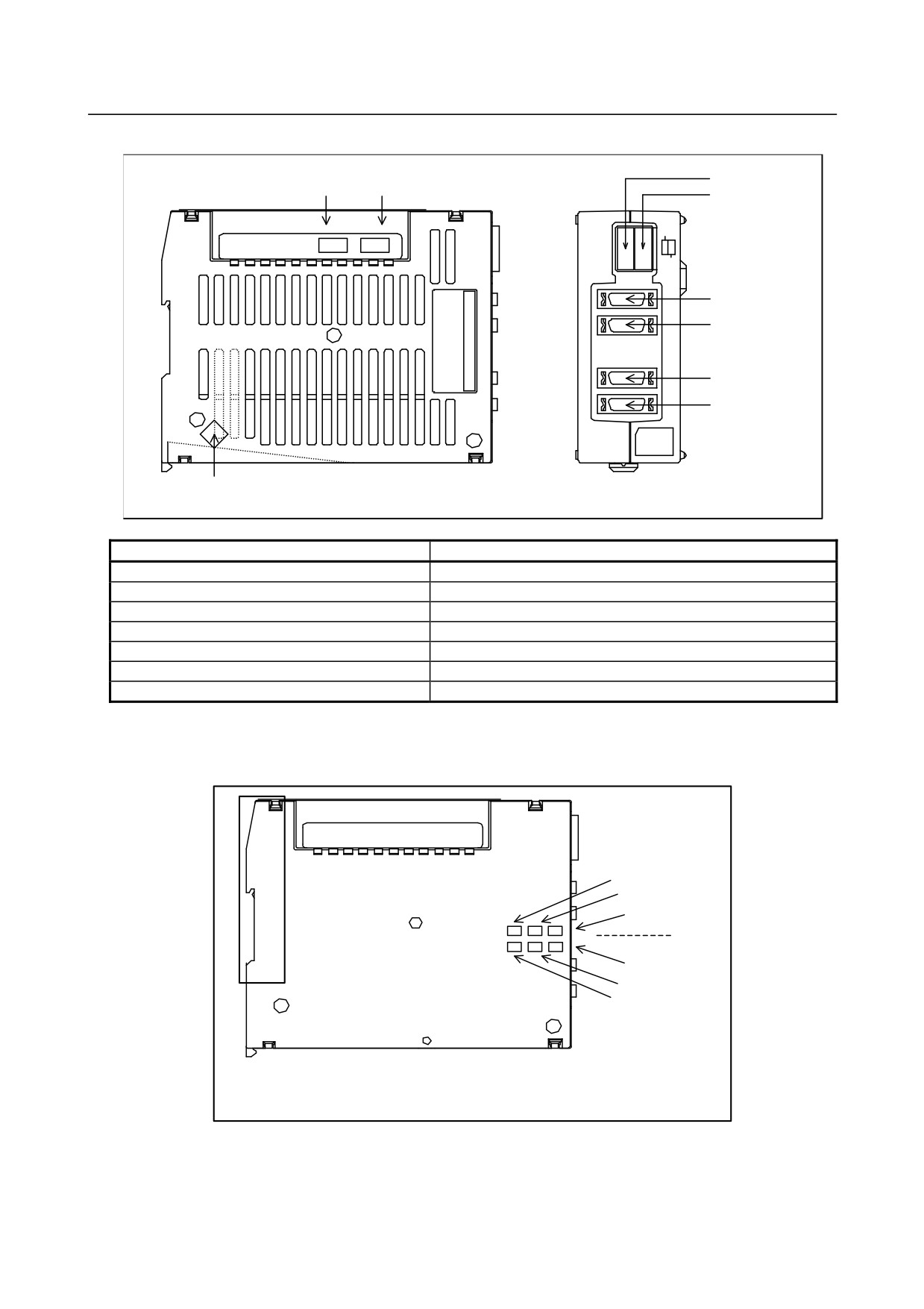
Connector and fuse locations
F1 (FUSE1) F2 (FUSE2)
CP1 (IN)
CP2 (IN)
JD1B1
JD1A1
JD1B2
JD1A2
GND
Connector number and fuse number
Application
CP1 (IN)
24 VDC power input (channel 1)
CP2 (IN)
24 VDC power input (channel 2)
JD1B1,JD1A1
I/O Link interface (channel 1)
JD1B2,JD1A2
I/O Link interface (channel 2)
GND
Signal ground terminal
F1 (FUSE1)
Fuse (channel 2, LED “FUSE1” lights if the relevant fuse blows)
F2 (FUSE2)
Fuse (channel 2, LED “FUSE2” lights if the relevant fuse blows)
-
LED display
The I/O Link connection unit has two I/O Link channels, each incorporating a green LED, “LINKn”, and
two red LEDs, “ALMn” and “FUSEn”, (where n is 1 or 2) as shown below.
Channel 1
FUSE 1 (red)
LINK 1 (green)
ALM1 (red)
ALM2 (red)
LINK 2 (green)
FUSE 2 (red)
Channel 2
See Subsection 4.2.1 for the correspondence between the on/off state of each LED and the status of the
I/O Link connection unit.
- 299 -
4.MAINTENANCE OF THE OTHER UNITS
B-64485EN/01
CAUTION
The I/O Link connection unit has two I/O Link channels, each having to be
supplied with 24 V.
If the LED “LINK1” neither steadily lights nor blinks, check for 24 V on the
connector CP1.
If the LED “LINK2” neither steadily lights nor blinks, check for 24 V on the
connector CP2
4.2.8
Standard Machine Operator's Panel [Supporting I/O Link i]
-
Specification
Name
Specification
Standard machine operators panel Main panel
A02B-0323-C231
Standard machine operators panel Sub panel A
A02B-0236-C232
Standard machine operators panel Sub panel D
A02B-0236-C244
Set of transparent key tops (55 key tops)
A02B-0236-K170
Set of blank key tops (55 key tops)
A02B-0236-K171
Set of symbol English key tops (34 labeled key tops + 21 blank key tops)
A02B-0236-K174
Set of blank key tops (100 red blank key tops)
A02B-0236-K175
Set of blank key tops (100 green blank key tops)
A02B-0236-K176
Set of blank key tops (100 blue blank key tops)
A02B-0236-K177
Set of blank key tops (100 yellow blank key tops)
A02B-0236-K178
Screw caps (with 5 pieces included)
A02B-0319-K191
Fuse
1A (spare parts)
A03B-0815-K001
- 300 -
B-64485EN/01
4.MAINTENANCE OF THE OTHER UNITS
-
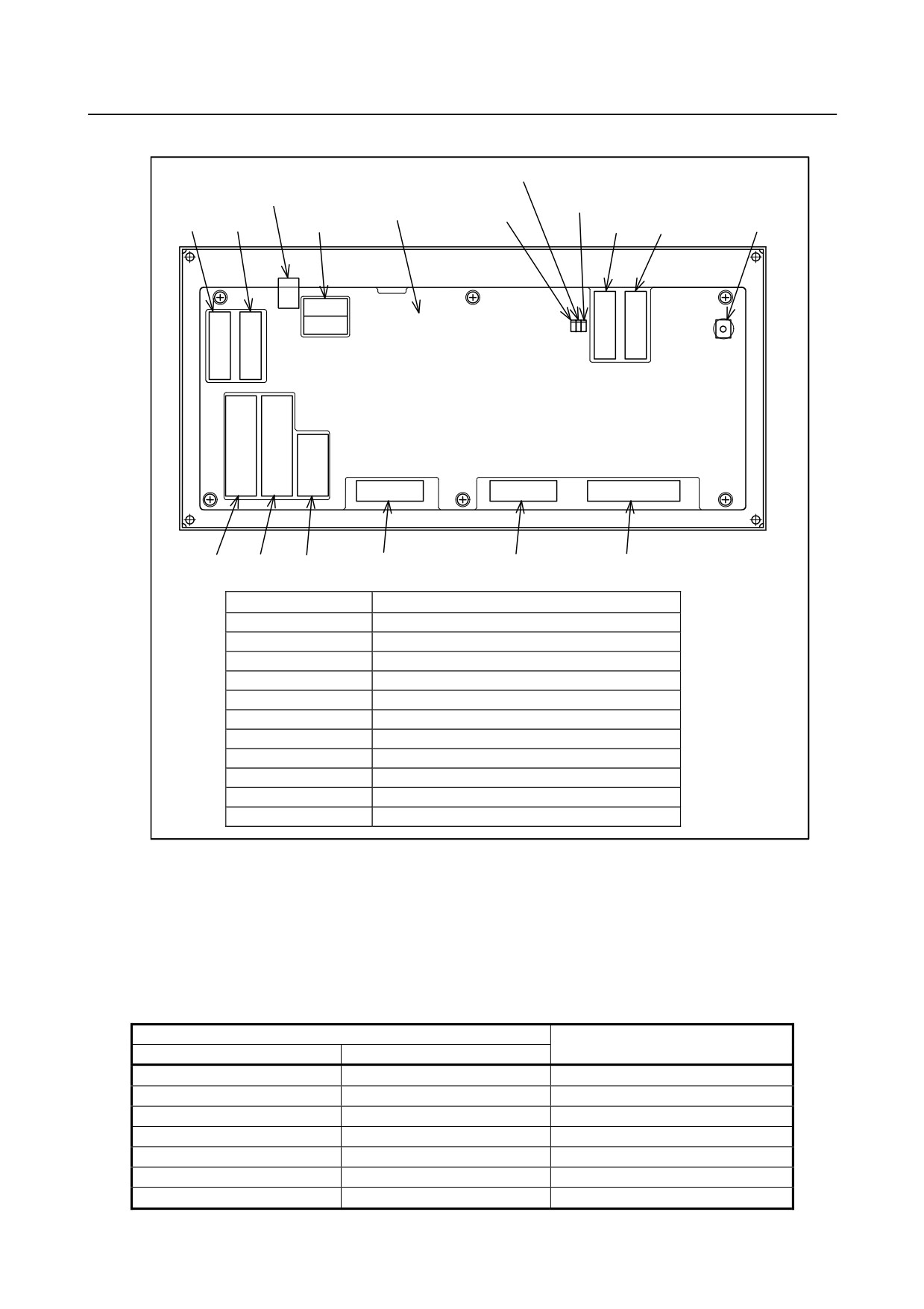
Connector and fuse locations
LINK LED
FUSE LED
(green)
Fuse
(red)
PCB
ALM LED
JA58 JA3
CA64
JD1B JD1A
Ground terminal
(red)
CM68 CM69
CM67
CM66
CM65
CA65
Rear view of main panel
Connector number
Use
JD1A
Second I/O Link i stage
JD1B
First I/O Link i stage
JA3
Manual pulse generator
JA58
Pendant type manual pulse generator
CA64
24VDC input/output
CA65
Connection to power magnetics cabinet
CM65
Rotary switch
CM66
Rotary switch
CM67
Memory protect, emergency stop signal
CM68
General purpose DI/DO
CM69
General purpose DI/DO
-
LED
The printed circuit board on the rear of the main panel machine operator's panel incorporates a green LED,
“LINK”, and two red LEDs, “ALM” and “FUSE”, as shown above.
See Subsection 4.2.1 for the correspondence between the on/off state of each LED and the status of the
main panel.
-
Correspondence between slot numbers and intra-slot byte addresses
The table below lists the slot number and intra-slot byte address for this operator’s panel.
Information output to the system relay area
Address of the DO driver which
Slot number
Alarm information number
detects an error
1
0
Yn1 error
1
1
Yn1+1 error
1
2
Yn1+2 error
1
3
Yn1+3 error
1
4
Yn1+4 error
1
5
Yn1+5 error
1
6
Yn1+6 error
- 301 -
4.MAINTENANCE OF THE OTHER UNITS
B-64485EN/01
Information output to the system relay area
Address of the DO driver which
Slot number
Alarm information number
detects an error
1
7
Yn1+7 error
4.3
UNITS SUPPORTING I/O Link
4.3.1
I/O Link-AS-i Converter
-
Specification
Name
Specification
For AS-i Ver2.0
A03B-0817-C001
For AS-i Ver2.1
A03B-0817-C002
Fuse 1A (spare parts)
A03B-0815-K001
-
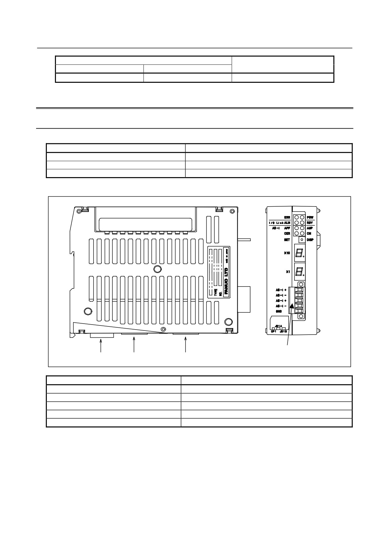
Locations of connectors
AS-i terminal block
CP1A,CP1B
JD1A
JD1B
Connector number
Application
CP1A
24 VDC power input
CP1B
24 VDC power output
JD1A
Second I/O Link i stage
JD1B
First I/O Link i stage
AS-i terminal block
AS-i communication cable connection
- 302 -
B-64485EN/01
4.MAINTENANCE OF THE OTHER UNITS
-
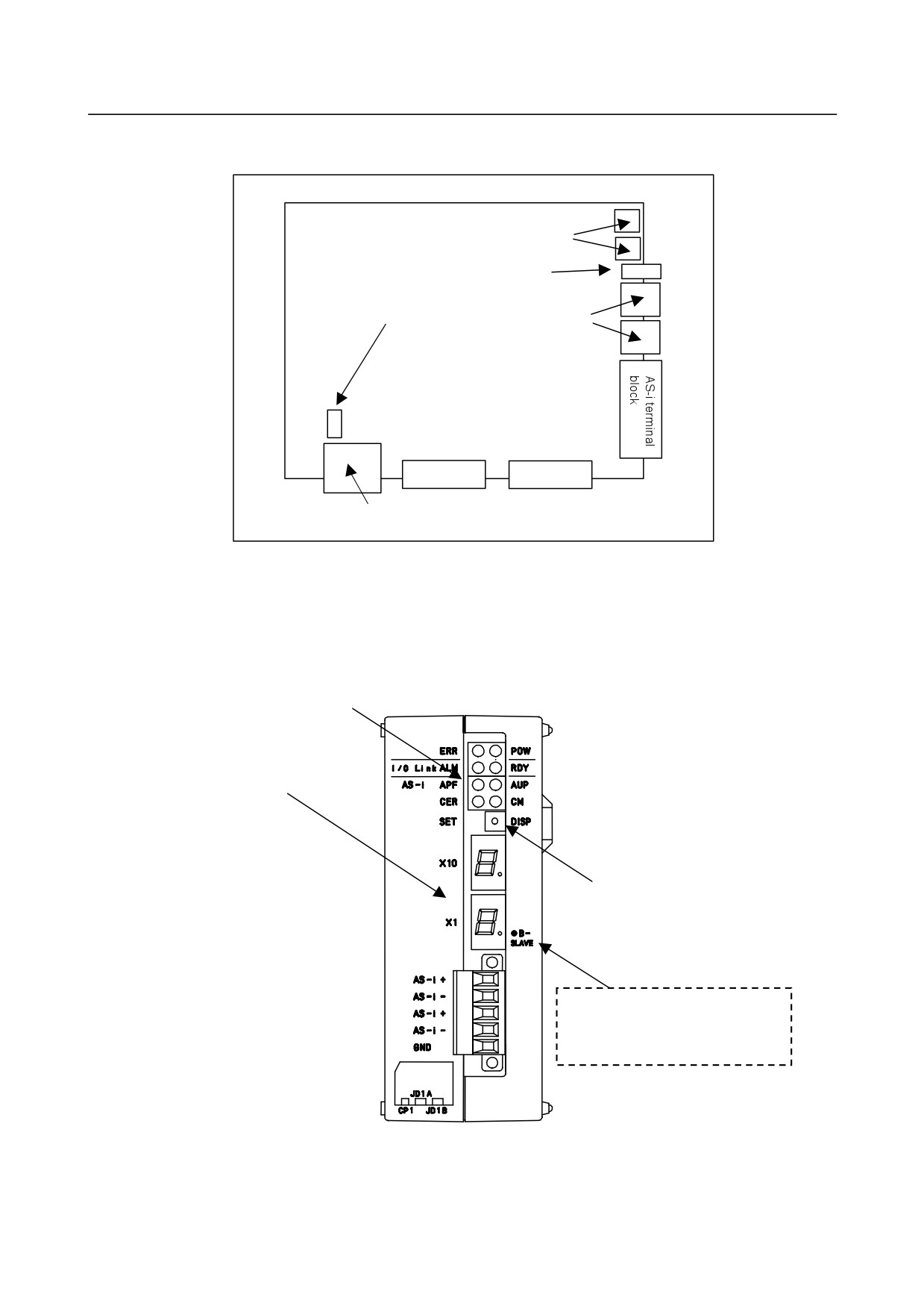
Locations of fuses
The fuse for the I/O Link-AS-i converter is on the printed circuit board in the case.
LED
Setting switch
Fuse
7-sgment LED
JD1A
JD1B
Power supply connector
-
LED displays and setting switch
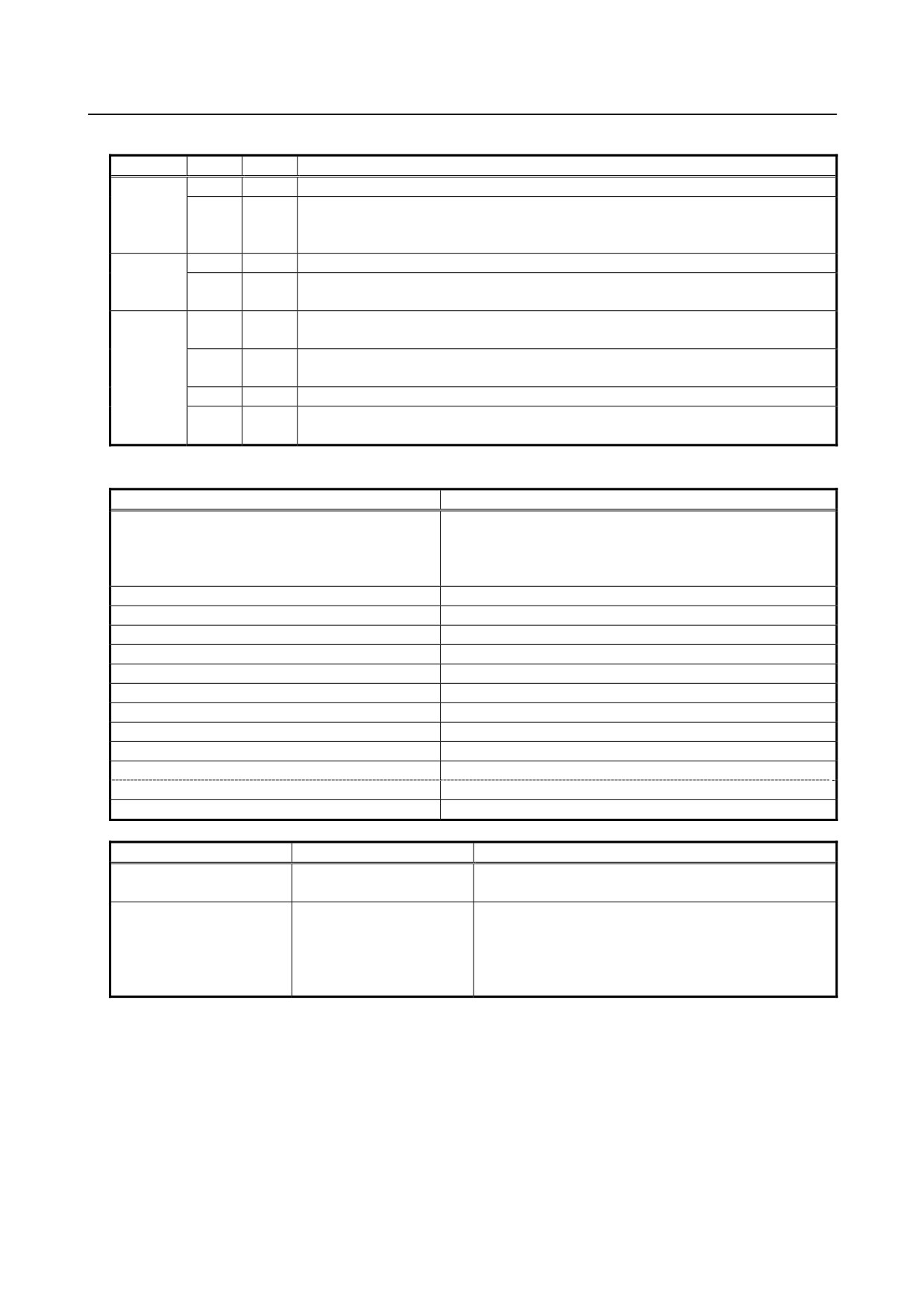
The I/O Link-AS-i converter is equipped with status display LEDs and a setting switch. The equipped
LEDs include four green, four red, and two 7-segment LEDs. Shown below are the location and use of
each LED as well as what the setting switch is used for.
(1) LED
(2) 7-segment LEDs
(3) Setting switch
Note: This label is only on Ver 2.1
of AS-i converter.
- 303 -
4.MAINTENANCE OF THE OTHER UNITS
B-64485EN/01
(1) LED display
Function
Label
Color
Description
POW
Green
Lights to indicate that the power for the I/O Link - AS-i converter is on.
ERR
Red
Lights to indicate a failure (whose details can be checked using the other LED
displays (including the 7-segment LED displays) and status information on the I/O
Link).
I/O Link
RDY
Green
Lights to indicate that the I/O Link is ready to communicate.
ALM
Red
Lights to indicate that an alarm condition (whose details can be checked using the
7-segment LED displays) has occurred on the I/O Link.
AS-i
AUP
Green
Lights to indicate that the current operation mode is the protected mode and
automatic address is available.
CM
Green
Lights to indicate that the current operation is the configuration mode and goes off to
indicate that the current operation is the protected mode.
APF
Red
Lights to indicate an AS-i power fail.
CER
Red
Lights to indicate that a registered slave configuration (LPS, ID code, or I/O
configuration) does not match the currently connected slaves.
(2) 7-segment LED displays
LED display
Description
No display
Normal operation
(If the setting switch is in the DISP position, the
LED displays light according to the operation mode
as listed below.)
E0
AS-i master error
E1
AS-i master EEPROM error
E2
ROM error
E3
RAM error
E5
Command execution error, SET switch execution error
E6
I/O Link slave watchdog alarm
E7
I/O Link RAM error
E8
Watchdog alarm 1
E9 or "⋅" (dot) at the tens digit
Watchdog alarm 2
00 to 31
Slave address display
"⋅" (dot) at the ones digit
Lights when the B slave address is displayed.
88
Initialize operation, mode shifting, AS-i power fail
Operation mode
Normal operation
When setting switch is in DISP position
Configuration mode
No display
The LES of each connected salve unit is displayed at
1-second intervals.
Protected mode
The lowest slave address
Each slave unit that has encountered a configuration
among those which
mismatch is displayed at 1-second intervals (in an
encountered a
LPS-LES mismatch list).
configuration mismatch is
Note: Nothing is displayed if there is no mismatched
displayed.
slave unit.
- 304 -
B-64485EN/01
4.MAINTENANCE OF THE OTHER UNITS
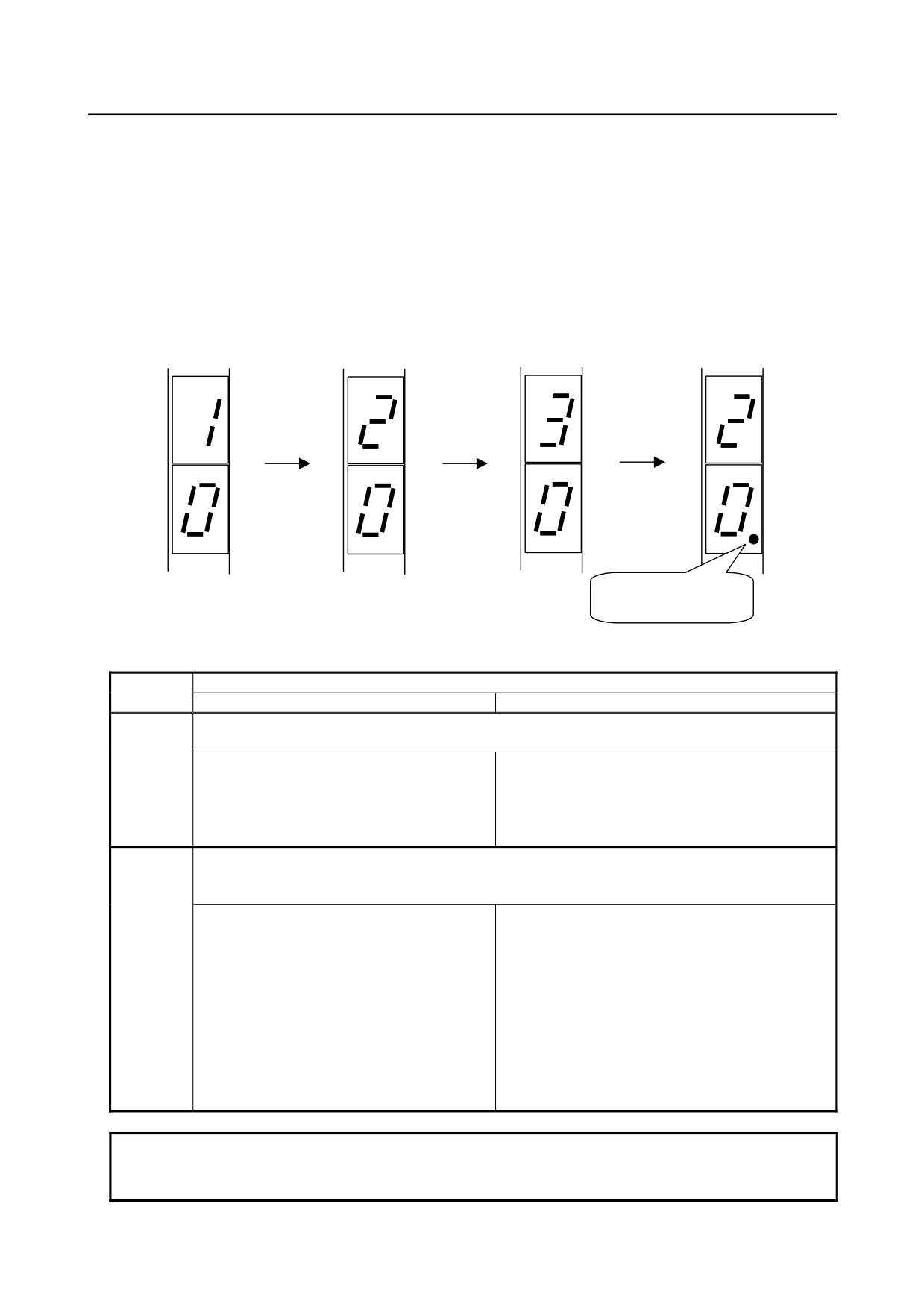
(a) Order in which Ver 2.1 displays slave numbers
The slave number of the standard slave or the A slave is displayed first (with "⋅" at the ones digit off). The
slave number of the B slave is displayed next (with "⋅" at the ones digit on).
Example: Address #10
Standard slave
Address #20A A/B slave
Address #20B
A/B slave
Address #30
Standard slave
If the above slave units are connected, their slave numbers are displayed in the order shown below.
Address #10
Address #20
Address #30
Address #20B
Standard slave
A/B slave
Standard slave
A/B slave
X10
X10
X10
X10
X1
X1
X1
X1
●B-
●B-
●B-
●B-
SLAVE
SLAVE
SLAVE
SLAVE
"⋅"
(dot) at the ones
digit lights.
(3) What the setting switch specifies
Setting
Operation mode
switch
Configuration
Protected mode
DISP
Slave addresses are displayed.
No other input is acceptable until all salve addresses are displayed.
The LES of each of all connected slaves are
Each slave unit which has encountered a
displayed at about 1-second intervals.
configuration mismatch is displayed at about
1-second intervals (in an LPS-LES mismatch list).
Note) Nothing is displayed if there is no
mismatched slave unit.
SET
The operation modes are switched.
Note) Keeping pressing the switch will not change the modes. Keep your hand off the switch for at
least 1 second to make it off.
Keeping pressing the switch for at least 5
Keeping pressing the switch for at least 5 seconds
seconds causes the current slave
selects the configuration mode.
configuration (LPS, ID code, I/O configuration,
and parameters) to be registered, enables
Note: Keeping pressing the switch for not longer
automatic addressing, and selects the
than 5 seconds causes nothing.
protected mode.
Note: Keeping pressing the switch for not
longer than 5 seconds selects the
protected mode but does not cause the
configuration to be registered or
enables automatic addressing.
NOTE
If a slave unit with address "0" is connected, no configuration registration is
made and the protected mode is not selected. Alarm "E5" is displayed.
- 305 -
4.MAINTENANCE OF THE OTHER UNITS
B-64485EN/01
-
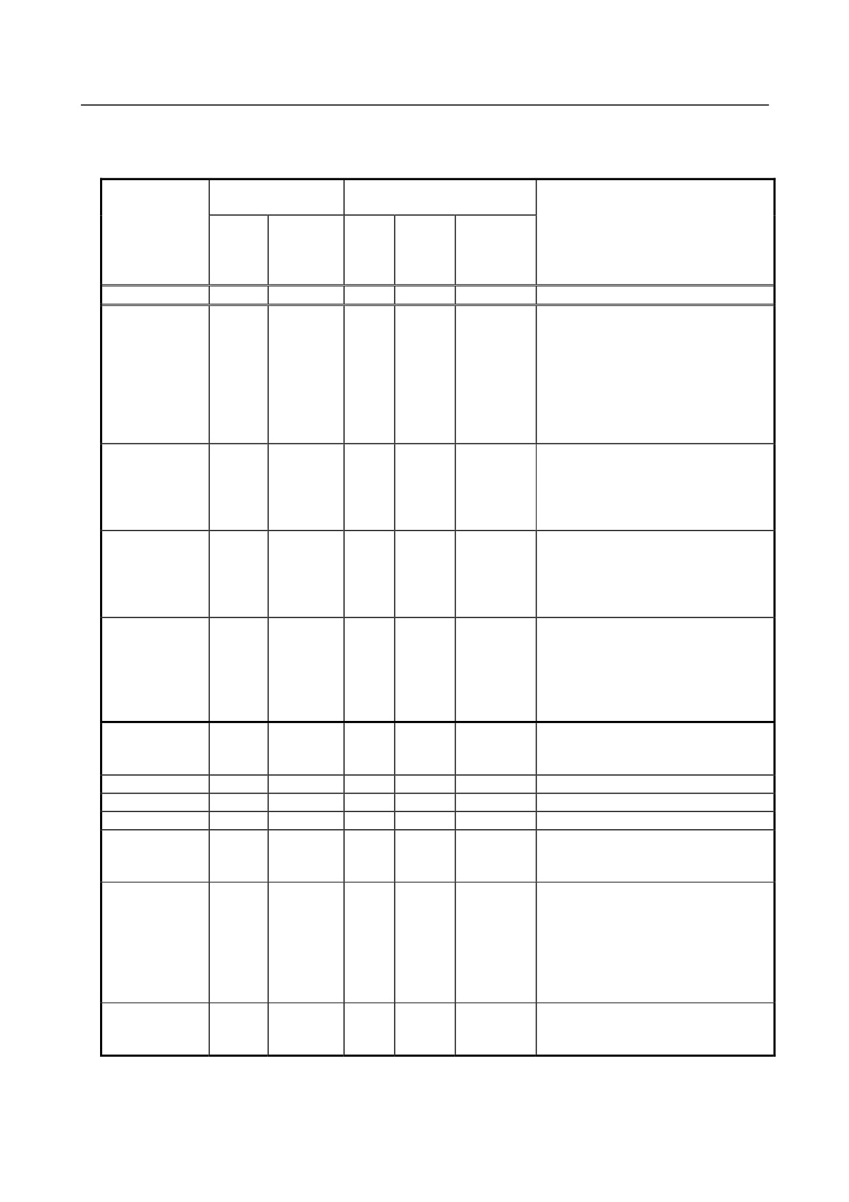
Dealing with errors
Check error status according to the LED display or status signals on the I/O Link.
Status signal on the I/O Link
LED display
(X represents a PMC address)
Alarm or
AS-i data
ERR
Possible cause and action
warning
7-segment
ready
LED
X+18
Other
LED
X+18
bit1
bit0
Normal operation
-
Off
0
1
-
-
Configuration
CER on
(Note)
0
1
X+16
The current slave configuration does not
mismatch
bit7=0
match the registered configuration. In the
protected mode, selecting DISP causes
the slave address encountering a
configuration mismatch to be displayed.
The possible causes include a slave unit
failure, broken AS-i cable, and
noise-induced AS-i communication error.
Initialization or
-
88
0
0
X+16
mode change in
bit0=1
progress
or
X+17
bit0=1
AS-i power fail
APF on
88
1
0
X+16
Check to see if the AS-i power supply is
bit1=1
normal and cables from the AS-i power
supply are normal.
Normal operation is resumed when the
AS-i power returns to normal.
AS-i master
ERR on
E1
1
0
X+17
Turn the power off and on again.
EEPROM fail
bit2=0
Because the configuration may be
corrupted, register the configuration
again (see NOTE on the next page). If
the alarm occurs again, replace the
converter unit.
AS-i master fail
ERR on
E0
1
0
X+18 bit2=1
Turn the power off and on again. If the
alarm occurs again, replace the
converter unit.
ROM fail
ERR on
E2
1
0
X+18 bit3=1
Replace the converter unit.
RAM fail
ERR on
E3
1
0
X+18 bit4=1
Replace the converter unit.
Watchdog 1
ERR on
E8
1
0
X+18 bit5=1
Replace the converter unit.
Watchdog 2
ERR on
E9 or ×10 "⋅"
1
0
-
An I/O Link system alarm occurred on
the host CNC.
Replace the converter unit.
I/O Link
ERR on
E6
-
-
-
An I/O Link system alarm occurred on
Slave
the host CNC.
Watchdog
The possible causes include a power
failure in another unit on the I/O Link and
a broken I/O Link cable as well as a
noise-induced I/O Link communication
error.
I/O Link RAM fail
ERR on
E7
-
-
-
An I/O Link system alarm occurred on
host CNC.
Replace the converter unit.
- 306 -
B-64485EN/01
4.MAINTENANCE OF THE OTHER UNITS
NOTE
-
In the protected mode, the lowest address number among those encountering a
configuration mismatch is displayed. In the configuration mode, nothing is
displayed.
-
Use ladder programs to detect and display converter unit errors.
-
If a converter unit error occurs, both the DO and DI are turned off.
-
If it is impossible to continue AS-i communication, a watchdog alarm condition
occurs in the slave unit. How the DO behaves at the watchdog alarm is
determined according to the slave unit type and parameter setting used. See
the relevant slave unit specification.
-
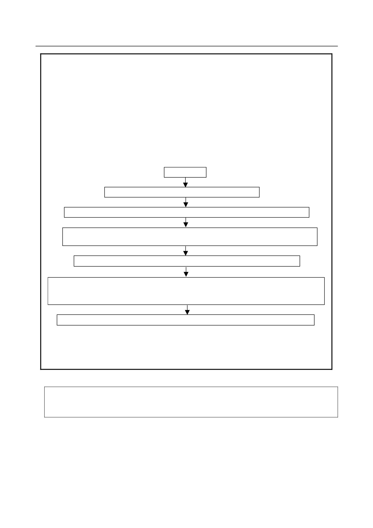
How to handle AS-i master EEPROM errors
If the 7-segment LEDs display "E1", it is likely that the registered configuration
may be corrupted. So, register it again according to the following chart.
Turn off power
Place switch in SET position, and turn on power again.
7-segment LED displays "E1" (keep switch in SET position).
Keep switch in SET position until LED "CM" changes from off to on or from on to off.
(This operation may take 5 seconds or more.)
Take your hand off switch, and turn power off and on again to restart system.
If 7-segment LEDs do not display "E1", registered configuration has been repaired.
(If LED "CM" lights, protect registered configuration for subsequent operation. Keep switch in SET position
until "E1" disappears. This operation takes 5 seconds or more.)
If 7-segment LEDs still display "E1", replace converter unit.
Note that if "E1" is displayed, the CNC may fail to start up.
The converter having this function is one shipped in or after June 2005.
Those shipped before do not support this function. If EEPROM fails to operate
normally, replace the converter unit.
-
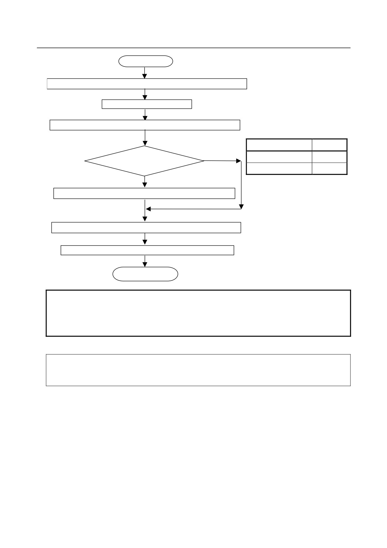
How to re-install
Once the I/O Link - AS-i converter is replaced, the new I/O Link - AS-i must be loaded with AS-i slave information
according to the following procedure.
The procedure can be executed even when no I/O Link is connected (when power is supplied to the I/O Link - AS-i
converter but not to the CNC or when no I/O Link cable is attached).
- 307 -
4.MAINTENANCE OF THE OTHER UNITS
B-64485EN/01
Start
Mount I/O Link-AS-i converter, AS-i slave, and AS-i power supply.
Connect AS-i cable.
Turn on power for I/O Link-AS-i converter and AS-i.
Mode
LED "CM"
YES
Configuration
On
Configuration mode?
Protected
Off
NO
Keep pressing SET switch for at least 5 seconds to select configuration mode.
Press DISP switch and check slave number of currently connected slave.
Keep pressing SET switch for at least 5 seconds to select protected
End of loading
NOTE
1 When the protected mode is selected, the slave configuration is registered, and
automatic addressing is enabled.
2 Turning the I/O Link-AS-i converter power on/off causes no operation mode
change. To change the operation modes, use the SET switch.
-
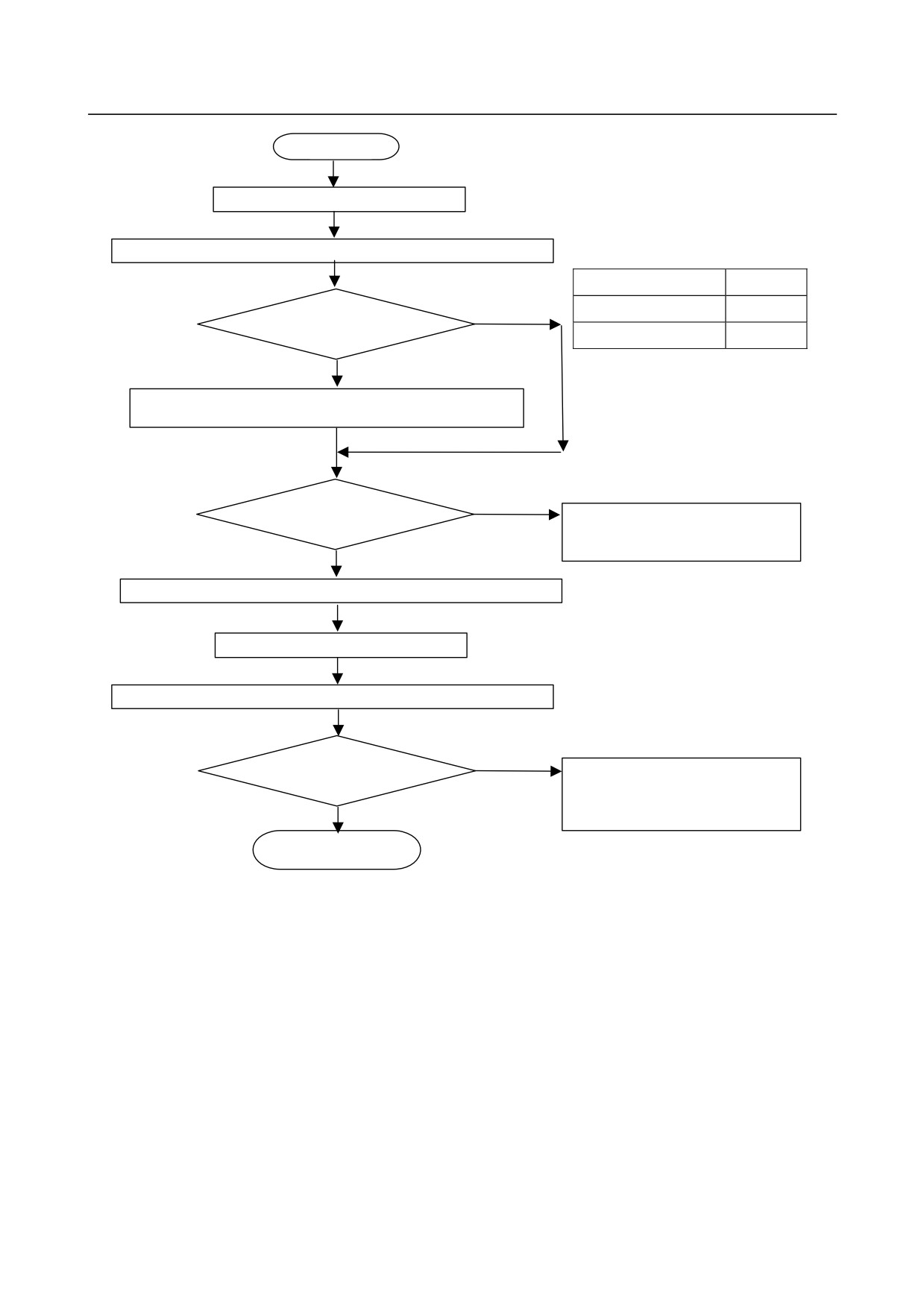
Operating procedure for AS-i slave replacement
Described below is the operating procedure for AS-i slave replacement (in case the slave is faulty). It is necessary
to set a slave address, using either of the following two:
(1) Commercially available address setting device.
(2) Automatic address setting function of the I/O Link-AS-i converter; how to use the function is explained below.
- 308 -
B-64485EN/01
4.MAINTENANCE OF THE OTHER UNITS
Start
Detach faulty AS-i slave.
Turn on power for I/O Link-AS-i converter and AS-i.
Mode
LED "CM"
YES
Configuration
On
Protected mode?
Protected
Off
NO
Keep SET switch flipped down for 1 second to enter protect mode. Note that
keeping it down for 5 seconds or longer causes configuration to be registered.
NO
Is AUP on?
The automatic address setting function is
unusable. Use an address setting
device, instead.
YES
Turn off power to each of I/O Link-AS-i converter and AS-i.
Attach new AS-i slave.
Turn on power to each of I/O Link-AS-i converter and AS-i.
NO
Are AUP and CER off?
The newly attached AS-i slave has a
nonzero address. Set its address to "0",
using an address setting device, or
YES
replace it with another slave.
End of address setting
- 309 -
4.MAINTENANCE OF THE OTHER UNITS
B-64485EN/01
4.4
SEPARATE DETECTOR INTERFACE UNIT
-
Specification
Name
Specification
Basic unit
A02B-0323-C205
Additional unit
A02B-0323-C204
-
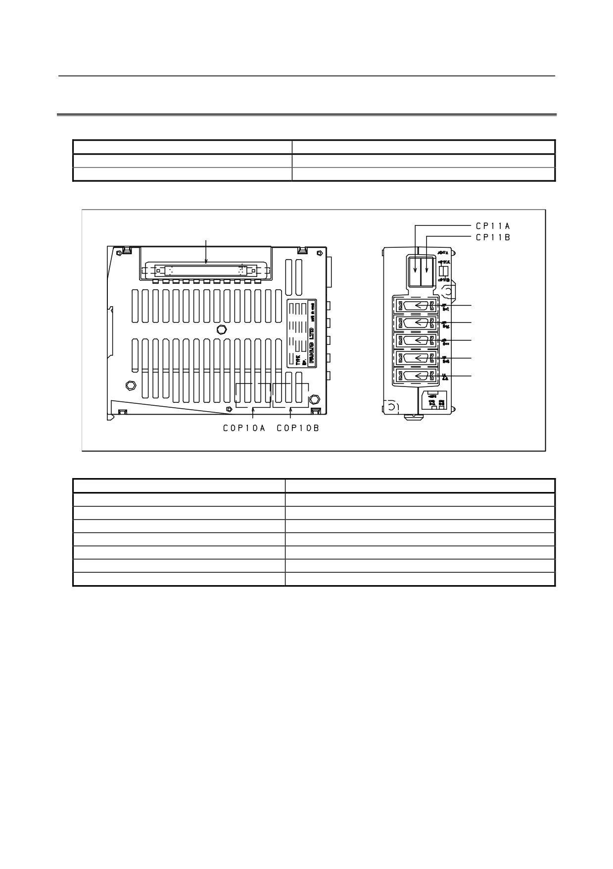
Connector mounting location
CNF1(CNF2)
JF101(JF105)
JF102(JF106)
JF103(JF107)
JF104(JF108)
JA4A
The parenthesized connector names are for the additional unit.
Connector number
Application
CP11A
24 VDC power input
CP11B
24 VDC power output
COP10A
Back stage of the FSSB interface
COP10B
Front stage of the FSSB interface
JF101 to JF104 (JF105 to JF108)
Separate detector interface
JA4A
Connection of a battery for the absolute detector
CNF1(CNF2)
Connection of the additional unit
The parenthesized connector names are for the additional unit.
-
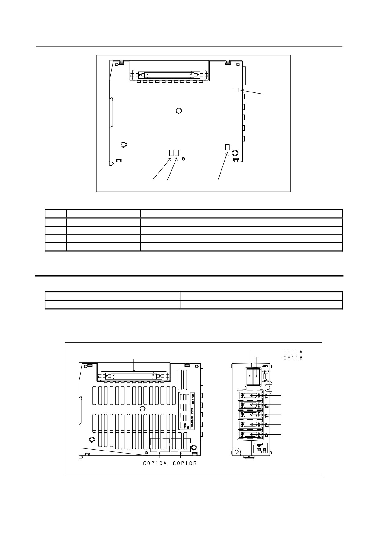
LED display
Status indication LEDs are installed on the board in the basic unit case. Two green LEDs (POWER and
OPEN) and two red LEDs (ERR1 and ERR2) are provided. The locations and meanings of the LEDs are
indicated below.
- 310 -
B-64485EN/01
4.MAINTENANCE OF THE OTHER UNITS
POWER
ERR1,ERR2
LINK
LED indication
No.
LED
Meaning
1
POWER
Turned on when the power is on
2
LINK
Turned on when FSSB communication is performed
3
ERR1
Turned on when COP10A (back stage) is disconnected
4
ERR2
Turned on when COP10B (front stage) is disconnected
4.5
Analog Input Separate Detector Interface Unit
-
Specification
Name
Specification
Basic unit
A06B-6061-C202
The additional unit A02B-0323-C204 mentioned in the previous subsection can be used with this interface
unit.
-
Connector mounting location
CNF1
JF111
JF112
JF113
JF114
JA4A
The parenthesized connector names are for the additional unit.
- 311 -