FANUC Series 30i-MODEL B, 31i-MODEL B, 32i-MODEL B. MAINTENANCE MANUAL - page 8
2.CONTROL UNIT HARDWARE
B-64485EN/01
-
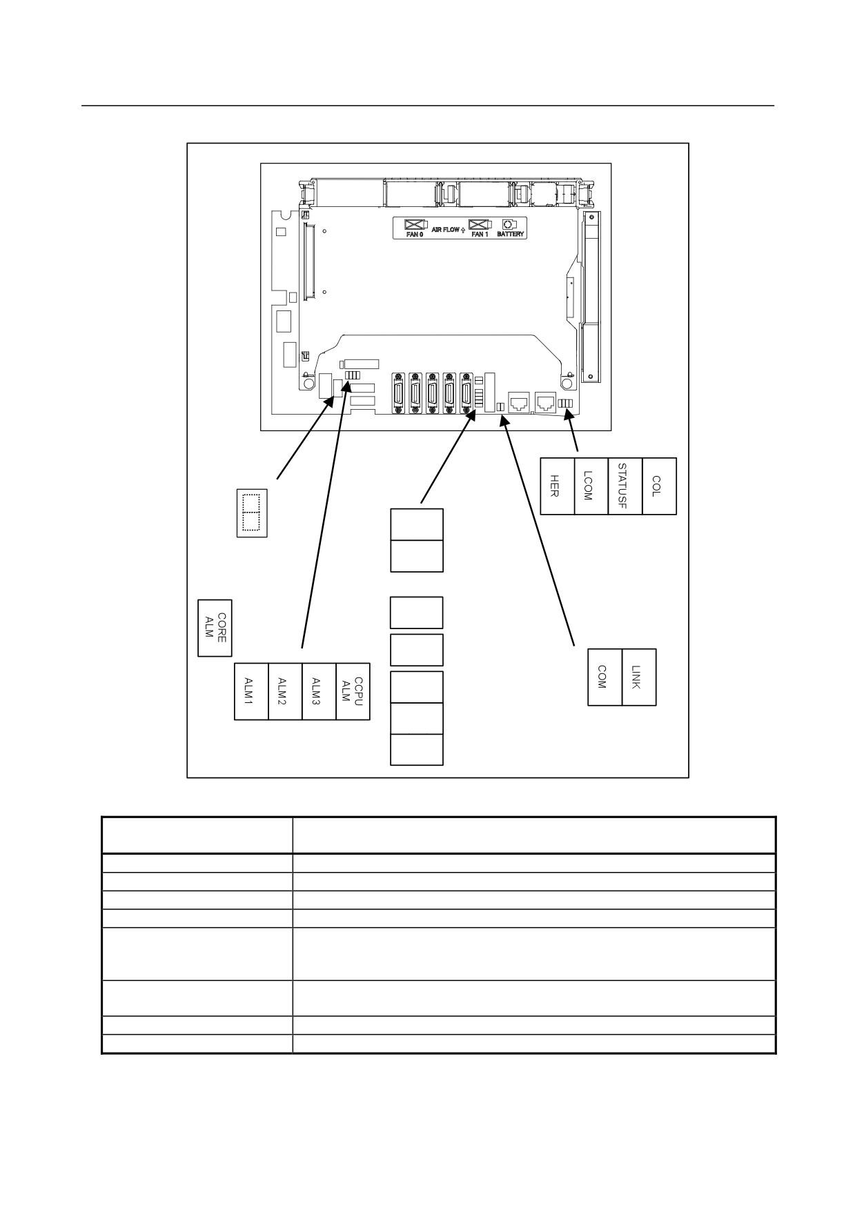
LED display
Rear view
DNV9
(red)
(yellow) (green) (red)
(3)
(7) Ethernet
DNV8
GUI status 2
(8) 7-segment LED
(Multi-function
LED (green)
Ethernet) status LED
DNV5
(5) LEDP (green)
DNV4
(4) GUI alarm LED
(red)
DNV3
(2) GUI status 1
LED (green)
DNV2
(yellow) (green)
(1)Alarm LED (red)
(6) Ethernet (Embedded
DNV1
Ethernet) status LED
(1) Alarm LED (red LED)
CORE ALM CCPU
Meaning
ALM
1
2
3 ALM
◇
□
■ □
◇
Low battery voltage. The battery may be is running out.
◇
■
■ □
◇
Software detected an error and stopped the system.
◇
□
□ ■
◇
Hardware detected a failure in the system.
◇
■
□ ■
◇
An alarm was issued with the servo card on the main board.
◇
□
■ ■
◇
An error was detected in the data of the SRAM on the FROM/SRAM module.
The FROM/SRAM module may be faulty, the battery voltage may have dropped, or
the main board may be faulty.
◇
■ ■ ■
◇
Abnormal power supply operation. The cause may be noise or the back panel (with
power supply) failure.
◇
◇ ◇ ◇
■
The CPU card may be faulty.
■
◇ ◇ ◇
◇
Lights if there is an abnormal condition in the power supply on the main board.
■: On
□: Off
◇: Don’t care
- 192 -
B-64485EN/01
2.CONTROL UNIT HARDWARE
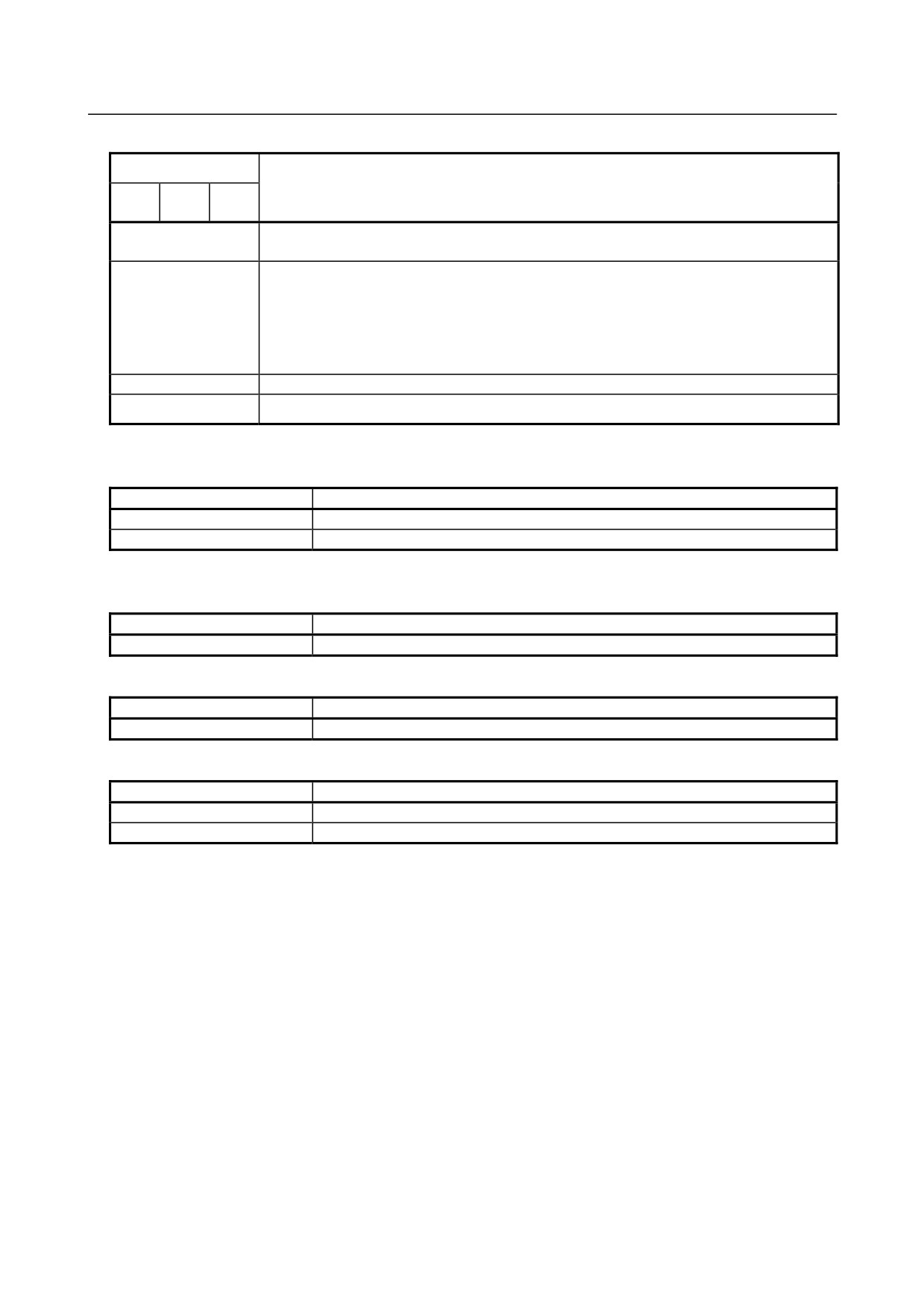
(2) GUI status 1 LED (green LED)
LED
Meaning
DNV3
DNV2
DNV1
(STA3)
(STA2)
(STA1)
State where the power is not tuned on, or state where the system was started up
□ □ □
successfully and is running normally.
State immediately after the power is turned on.
If the state remains unchanged:
If “CCPUALM” is on:
■ ■ ■
It is likely that the CPU card may be defective.
If “CCPUALM” is off:
It is likely that the main board or GUI card may be defective.
■ ■ □
The NCBoot32 screen is active.
□ ■ □
IPL processing is under way.
■: On
□: Off
(3) GUI status 2 LED (green LED)
LED
Meaning
DNV8 (LED2)
Indicates the operation status of the personal computer function.
DNV9 (LED1)
Indicates the operation status of the personal computer function.
■: On
□: Off
(4) GUI alarm LED (red LED)
LED
Meaning
DNV4 (RAME)
Common RAM error. The main board may be faulty.
(5) LEDP (green LED)
LED
Meaning
DNV5 (LEDP)
Turned on when power is supplied to the GUI card.
(6) Ethernet (Embedded Ethernet) status LED
LED
Meaning
LINK (green)
Turned on when a connection is made with the hub correctly.
COM (yellow)
Turned on when data is transferred.
- 193 -
2.CONTROL UNIT HARDWARE
B-64485EN/01
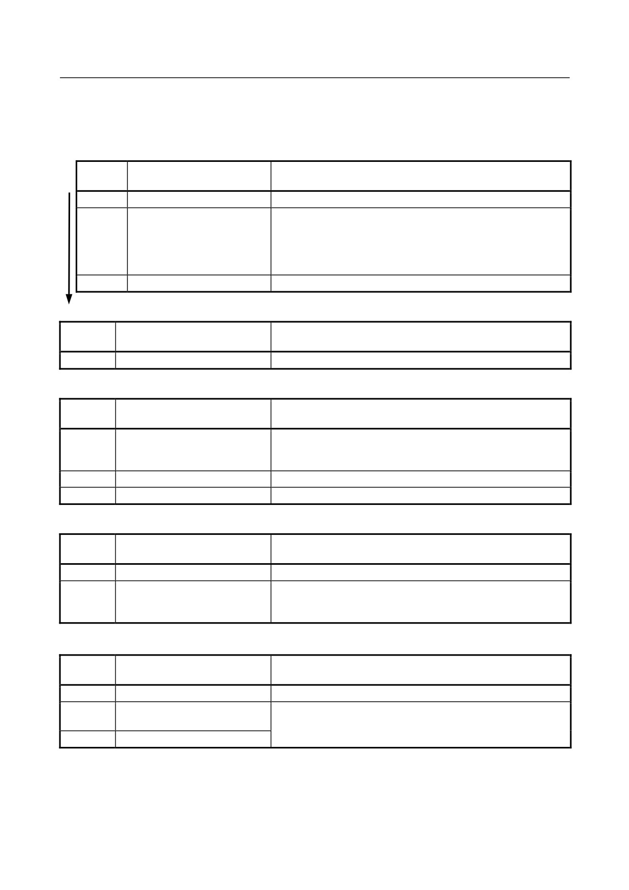
(7) Ethernet (Multi-function Ethernet) status LED
In the following explanations, the LED lighting states are expressed as follows:
□: Off
■: On
☆: Blinking
◇: Don’t care
-
LED display transition for STATUSF (power on state)
LED
Status
Meaning
display
□
Power-off
■
Immediately after power-on
Initial state entered immediately after power-on.
If LED is stopped in this condition, the cause is one of the following:
→ The CNC communication software may not be running normally.
Check whether the communication software is installed properly.
→ The main board may be faulty. Replace the main board.
☆
Start completion
The Multi-function Ethernet function has started normally.
-
LED display for STATUSF (during normal operation)
LED
Status
Meaning
display
☆
Normal status
The Multi-function Ethernet function is operating normally.
-
LED display for LCOM
LED
Status
Meaning
display
□
Not connected to hub
The board is not connected to the hub properly.
The LED stays off also when the power to the hub is off.
Check whether the board is connected to the hub properly.
■
Connected to hub
The board is connected to the hub.
☆
Transmission/reception in progress
Data is being transmitted or received.
-
LED display for COL
LED
Status
Meaning
display
□
Normal status
The Multi-function Ethernet function is operating normally.
■
Collision occurs.
The LED is on or blinks at short intervals when the Ethernet
☆
(Data collision occurs.)
communication traffic (communication amount) is high or ambient
noise is high.
-
LED display for HER
LED
Status
Meaning
display
□
Normal status
The Multi-function Ethernet function is operating normally.
■
Error detected in the Ethernet
The cause may be the faulty main board or a malfunction due to
circuit on the main board
noise.
☆
Error detected in the software
(8)
7-segment LED
See Appendix E, “LED Display”.
- 194 -
B-64485EN/01
2.CONTROL UNIT HARDWARE
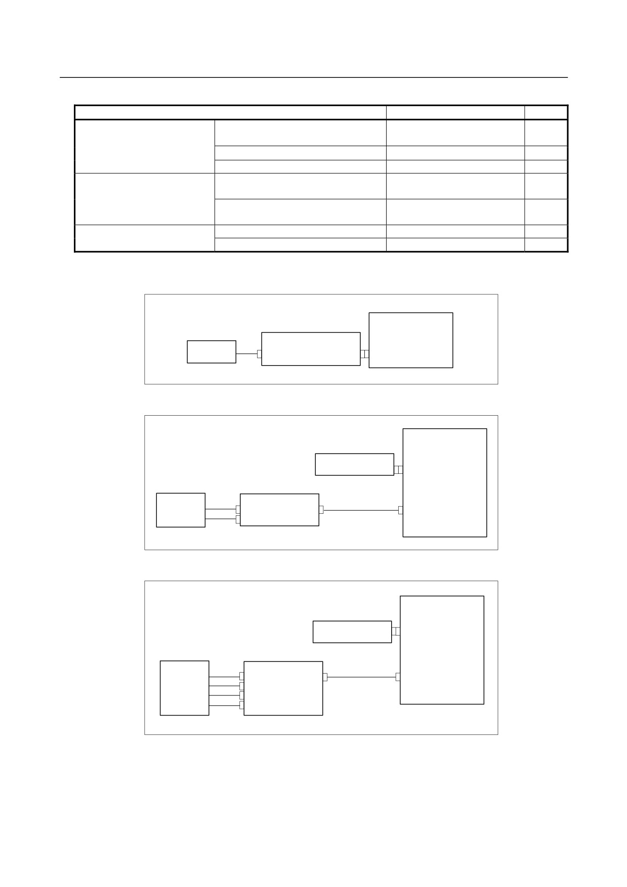
Inverter board and fan adapter board specification
Name
Specification
Remark
Inverter board
For 10.4” LCD (working also as fan
A20B-8200-0662
adapter board)
For 12.1” LCD
A14L-0143-0003
For 15” LCD
A14L-0168-0001
Fan adapter board
For 10.4” LCD (working also as fan
Works also as the inverter
adapter board)
board mentioned above.
For 12.1” LCD
A20B-8200-0669
For 15” LCD
Main board-to-inverter board
For 12.1” LCD
A660-4042-䌔075#L90R00
connection cable
For 15” LCD
A660-4042-䌔076#L75R00
-
Details of the inverter board
(1) For control unit with 10.4” LCD
Main board
Inverter board
10.4”LCD unit
(Also functions as a fan adapter board.)
CA132
CP1
CN1
(2) For control unit with 12.1” LCD
Main board
Fan adapter
CA132
CN1
12.1”LCD unit
Inverter board
CA134
CN2
CN1
Inverter connection cable
CN3
(3) For control unit with 15” LCD
Main board
Fan adapter board
CA132
CN1
15”LCD unit
Inverter board
CA134
CN02
CN01
Inverter connection cable
CN03
CN04
CN05
- 195 -
2.CONTROL UNIT HARDWARE
B-64485EN/01
-
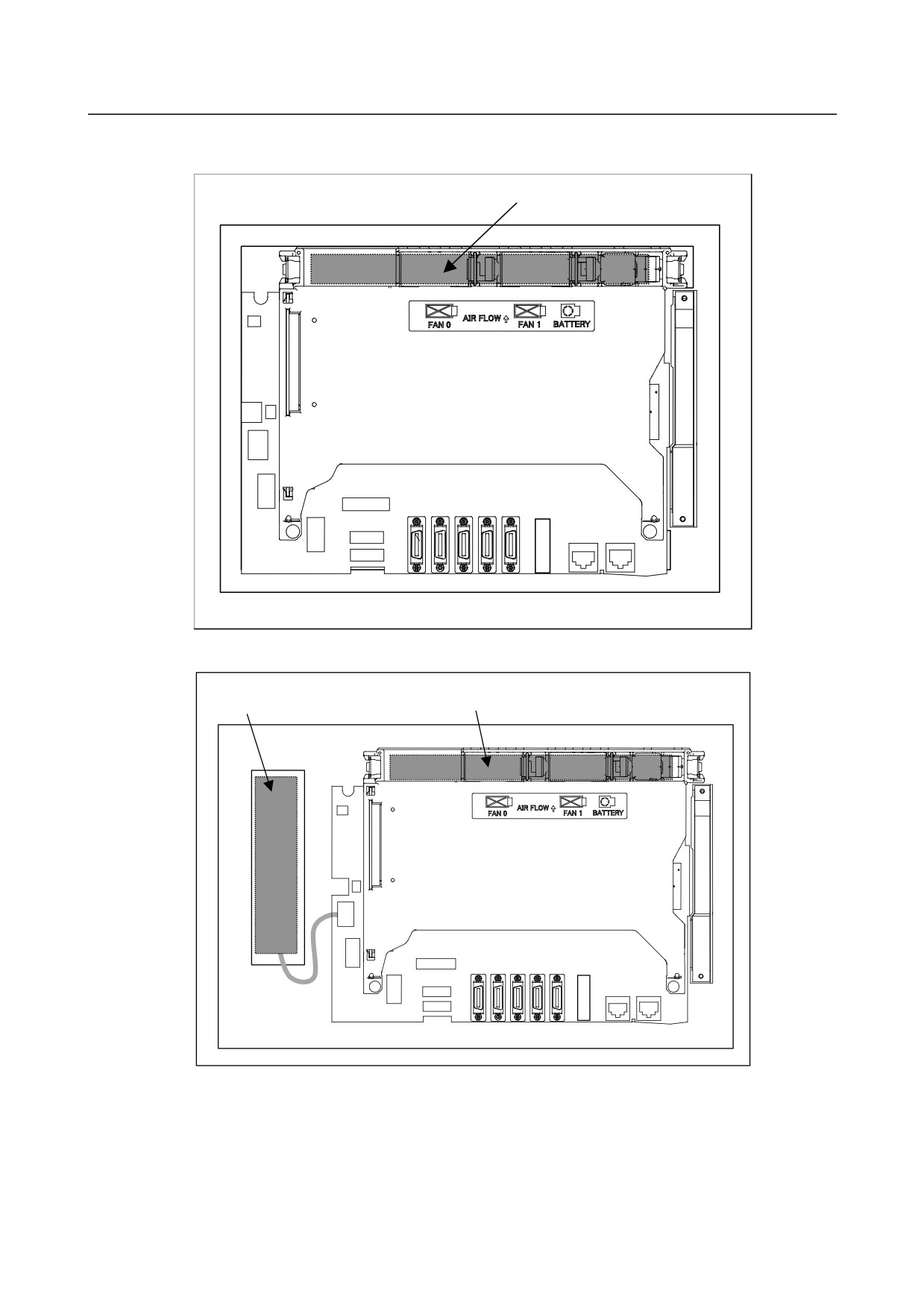
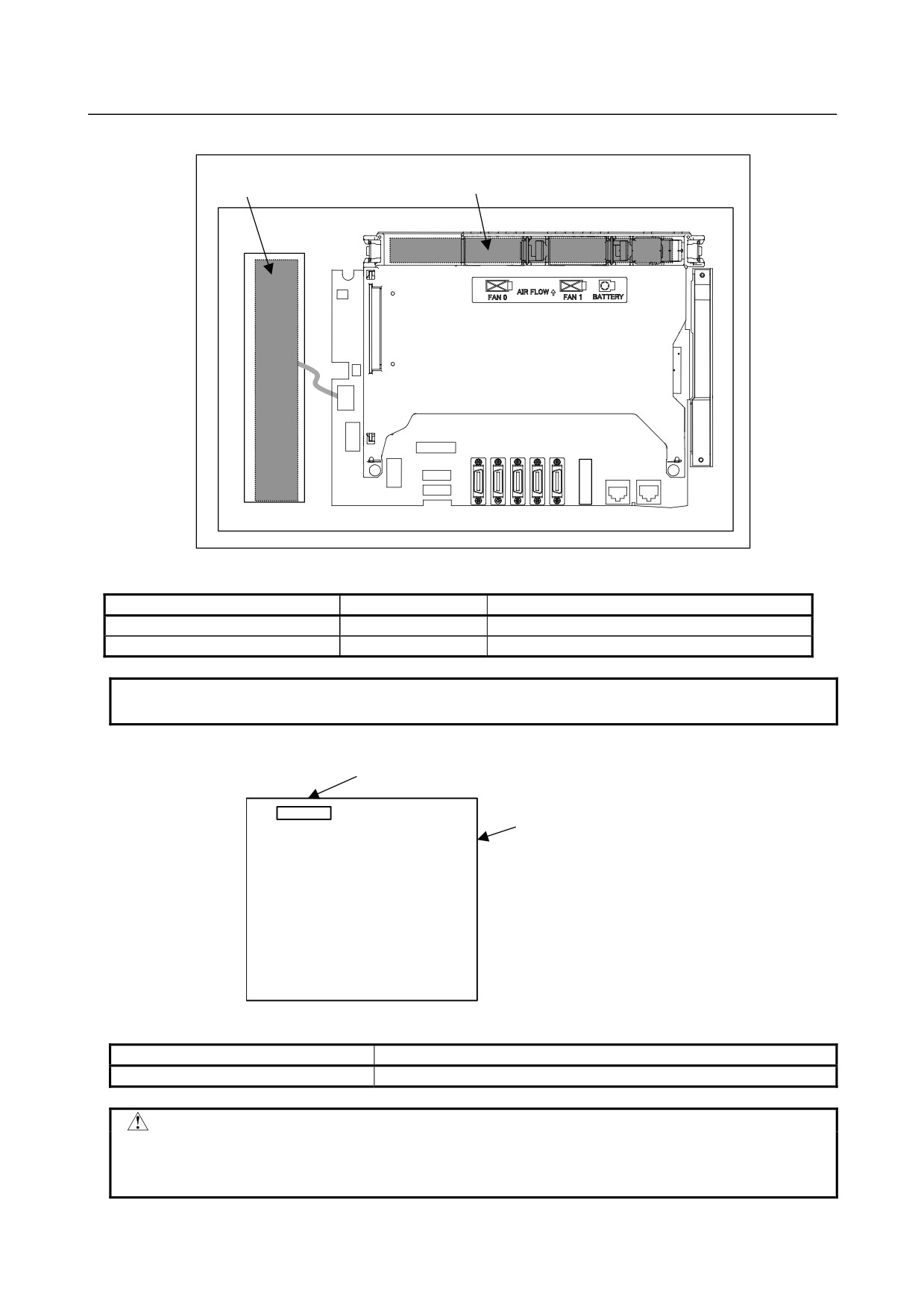
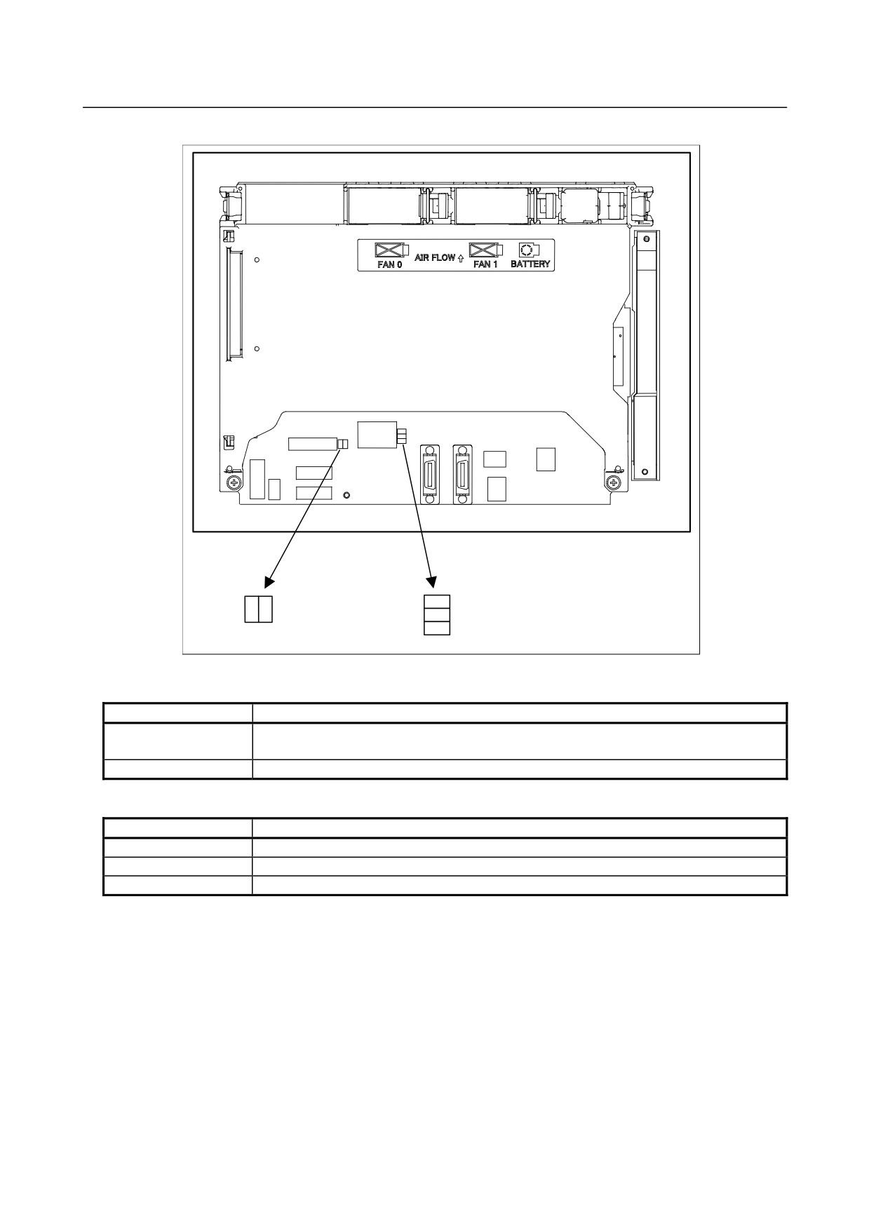
Locations of the inverter board and fan adapter board
(1) For control unit with 10.4” LCD
Inverter board
Rear view
(2) For control unit with 12.1” LCD
Inverter board
Fan adapter board
Rear view
- 196 -
B-64485EN/01
2.CONTROL UNIT HARDWARE
(3) For control unit with 15” LCD
Inverter board
Fan adapter board
Rear view
-
Backup unit specification
Name
Specification
Remark
Backup unit board
A20B-2100-0820
Backup unit cable
A02B-0323-K801
NOTE
Some configurations contain no backup unit.
-
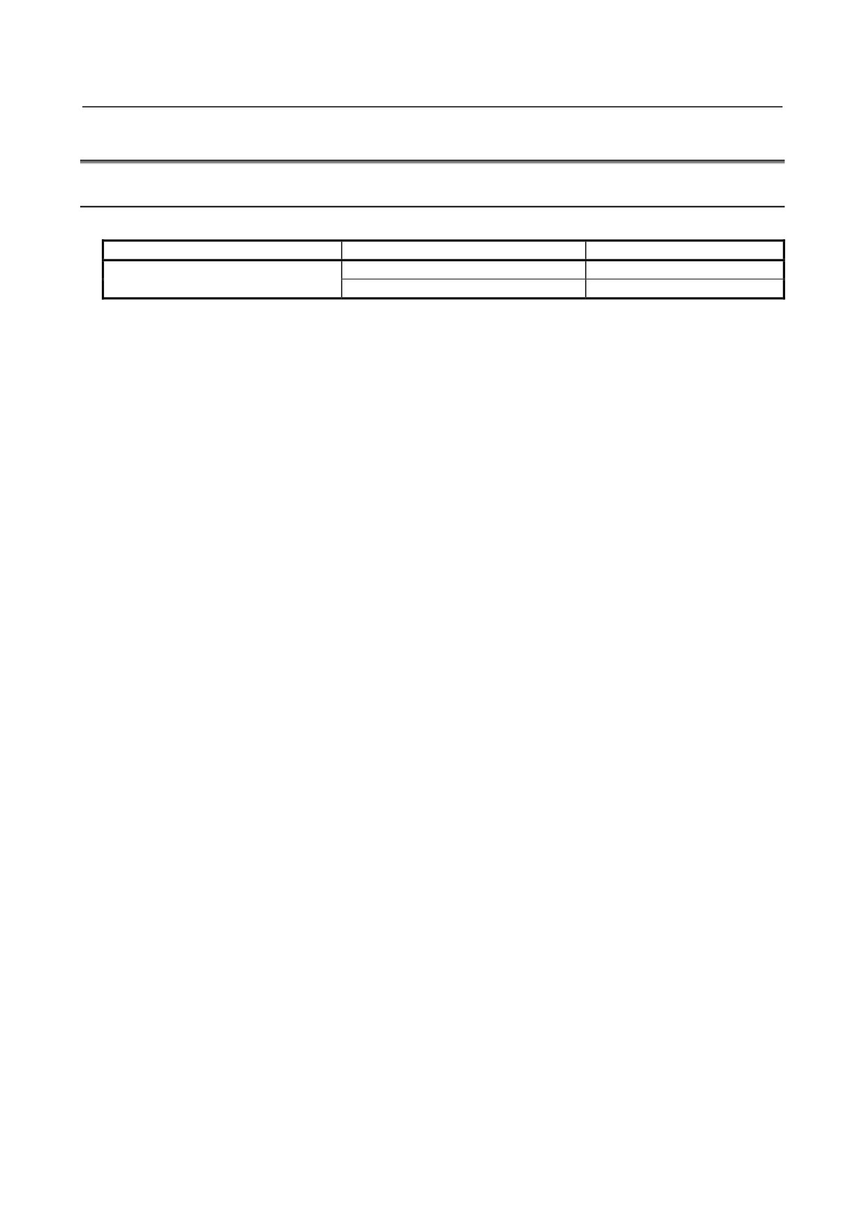
Connector mounting location
CN9
Backup unit board
Front view
Connector name
Function
CN9
Supplies backup power.
WARNING
When the LED (LEDP) on the main board lights, do not touch any component in
the basic and backup units. The personal computer function with Windows® CE
remain active for up to 12 seconds after the main power supply is turned off.
- 197 -
2.CONTROL UNIT HARDWARE
B-64485EN/01
2.5
HARDWARE OF STAND-ALONE TYPE CONTROL UNIT
2.5.1
Stand-alone Type Control Unit
-
Main board specification
Name
Specification
Remark
Main board
A16B-3200-0710
A16B-3200-0711
- 198 -
B-64485EN/01
2.CONTROL UNIT HARDWARE
-
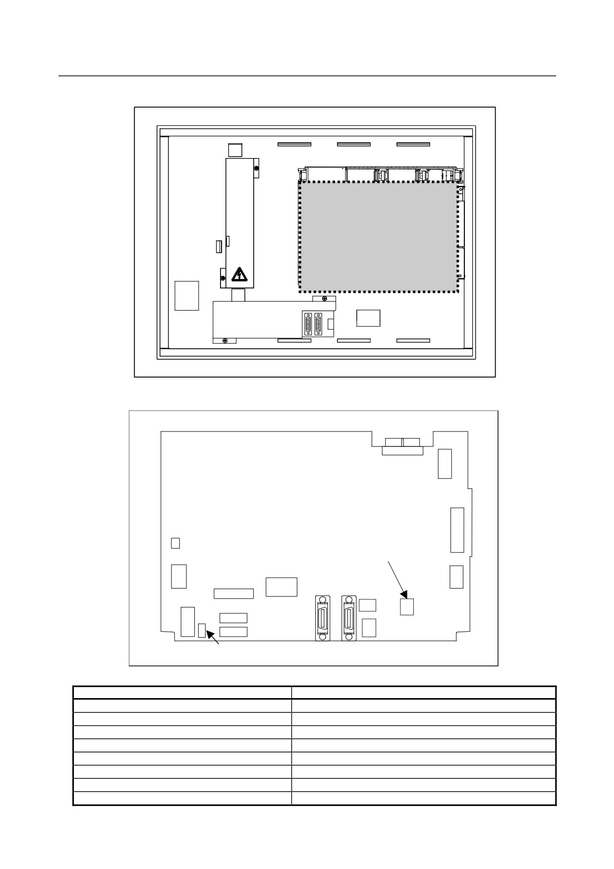
Mounting positions of connectors, LEDs, etc.
Battery
BAT1: For battery
JD56A: For I/O device interface (RS-232C)
JD36A: For I/O device interface (RS-232C)
CNM1B: For memory
JD51A: For I/O Link i or I/O Link
card interface
JA40: For high-speed skip
LINK,COM: LED for Ethernet
CD38A: Connector for Ethernet (Embedded Ethernet)
FUSE ALM: Fuse burn-out detection LED
CPD19A (right): For 24VDC power supply input
CPD19B (left): For 24VDC power supply output
COP21A: For HSSB interface
COP10A-2: For FSSB interface
STATUS: 7-segment LED
ALARM: Alarm LED
COP10A-1: For FSSB interface
MTSW: Rotary SW
PSW: Push SW
COREALM: Alarm LED
GND: SG connection terminal
STATUS 7-segment LED
This LED indicates the state of the control unit. This LED is used also for setting and maintenance
using the rotary switch MTSW and the push switch PSW.
MTSW rotary switch
This rotary switch is used for setting and maintenance operations, in combination with the STATUS
7-segment LED and the PSW push switch.
PSW push switch:
This push switch is used for setting and maintenance operations, in combination with the STATUS
7-segment LED and the MTSW rotary switch.
- 199 -
2.CONTROL UNIT HARDWARE
B-64485EN/01
-
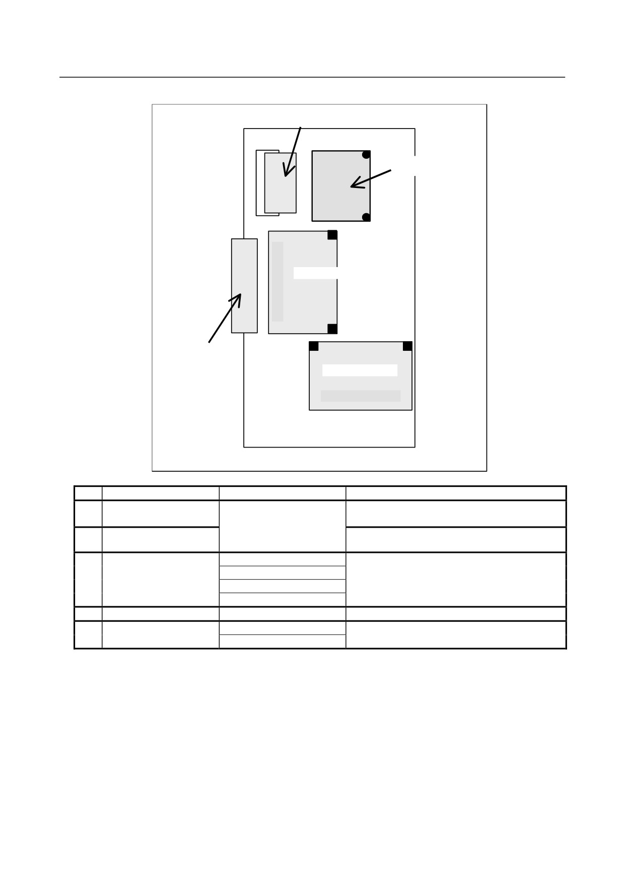
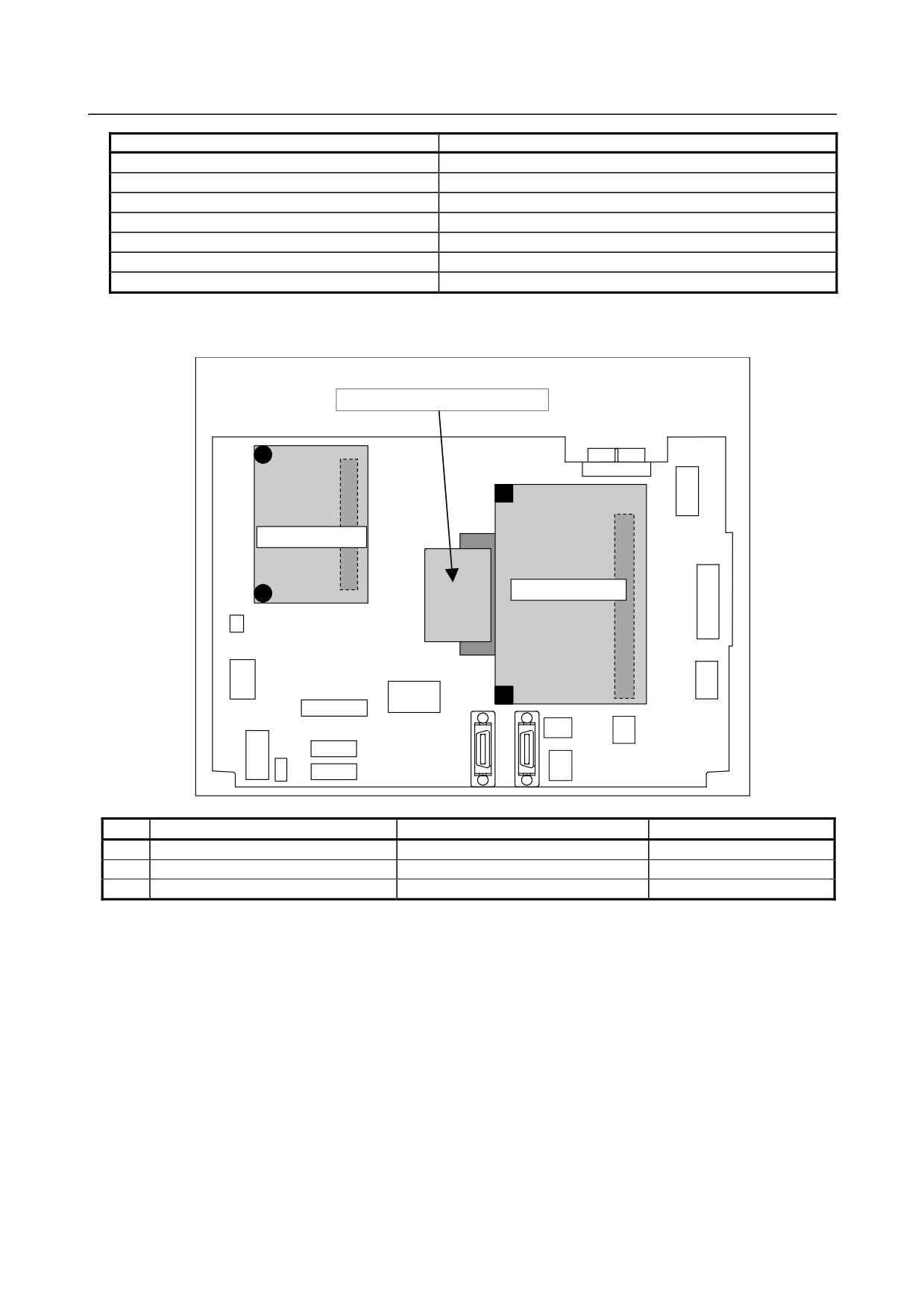
Mounting positions of cards, power supply unit, and FROM/SRAM module
(3) FROM/SRAM module
(4) Power supply unit
(2) CPU card
(5) Back panel
(1) Servo card
No.
Name
Specification
Remark
(1)
Servo card
See Subsection 2.4.1,
“LCD-mounted Type Control
(2)
CPU card
Unit (8.4” LCD Unit and 10.4”
LCD Unit A)”.
(3)
FROM/SRAM module
A20B-3900-0250
FROM stores various control software products.
A20B-3900-0251
The SRAM is a battery-backed memory module.
A20B-3900-0252
A20B-3900-0260
(4)
Power supply unit
A20B-8101-0011
(5)
Back panel
A20B-2003-0580
A20B-2003-0650
- 200 -
B-64485EN/01
2.CONTROL UNIT HARDWARE
-
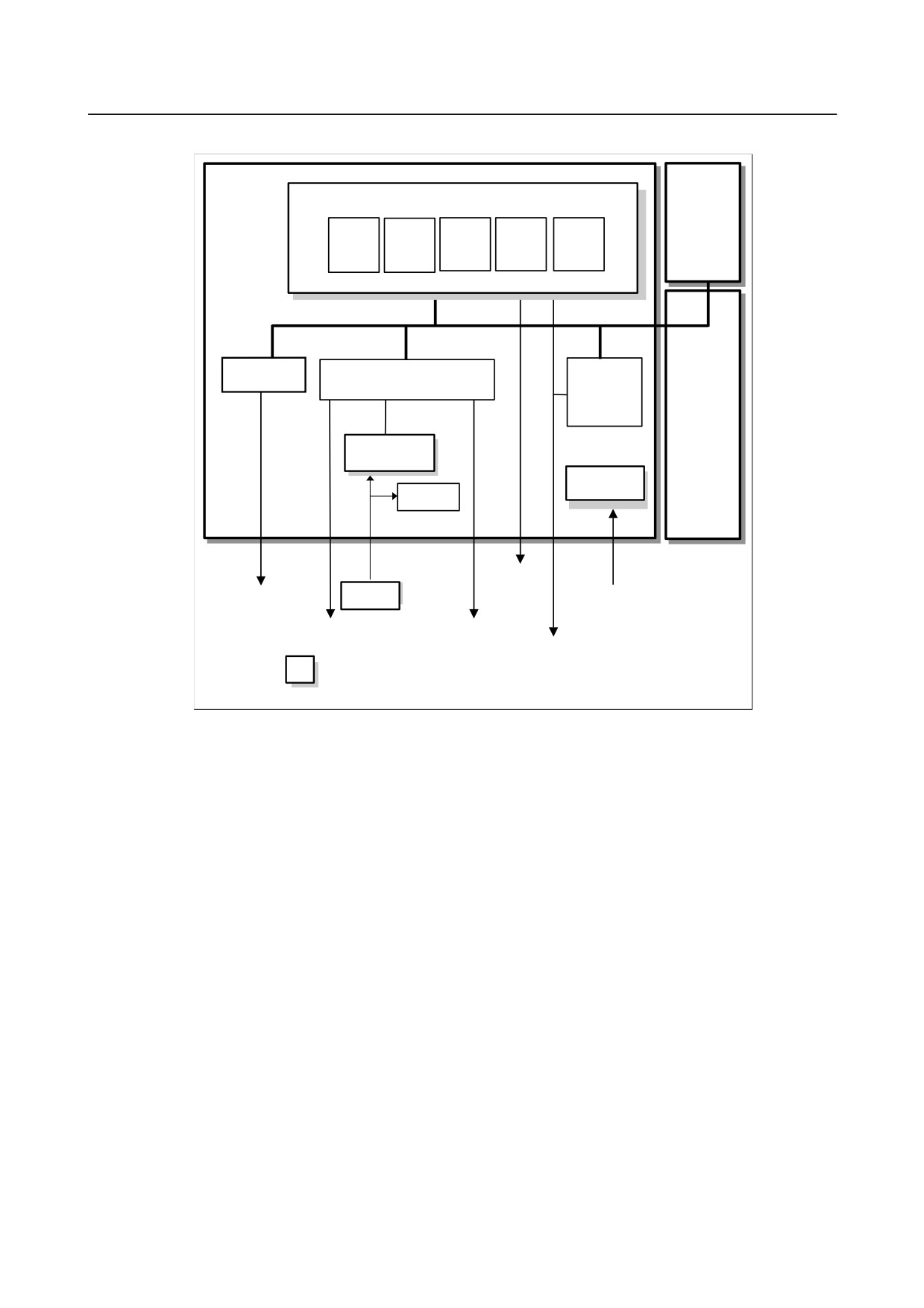
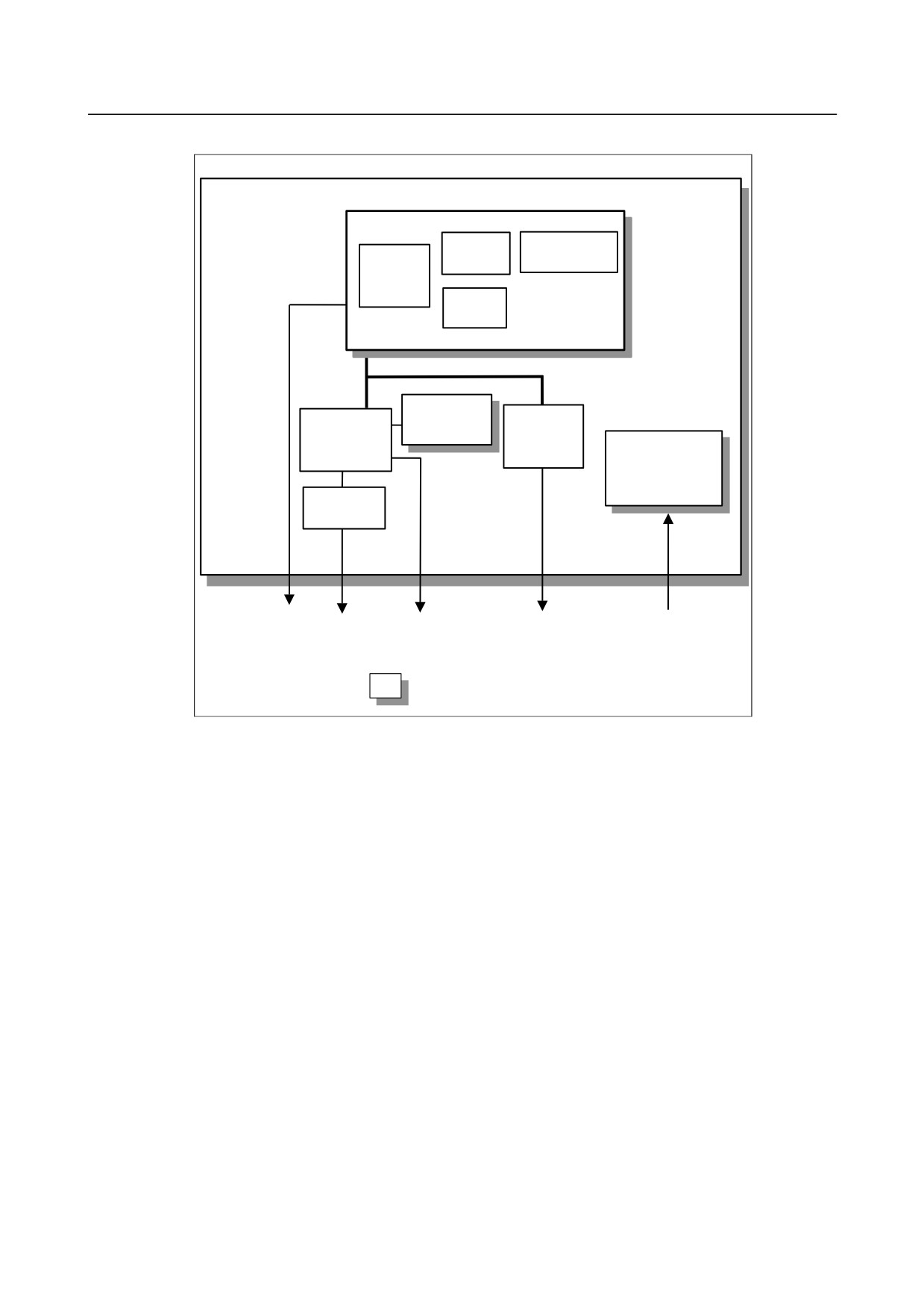
Block diagram
Optional board
Main board
CPU card
CPU
DRAM
BOOT
Ethernet
I/O Link
software
control
control
Servo card
Peripheral control
I/O Link i,
Back panel
I/O Link
control
FROM/SRAM
module
Power supply
unit
Calendar
function
Ethernet
(Embedded
FSSB
Battery
Ethernet)
24VDC
HSSB
MDI
RS232C
Memory card
I/O Link i
High-speed skip
I/O Link
: Detachable
- 201 -
2.CONTROL UNIT HARDWARE
B-64485EN/01
-
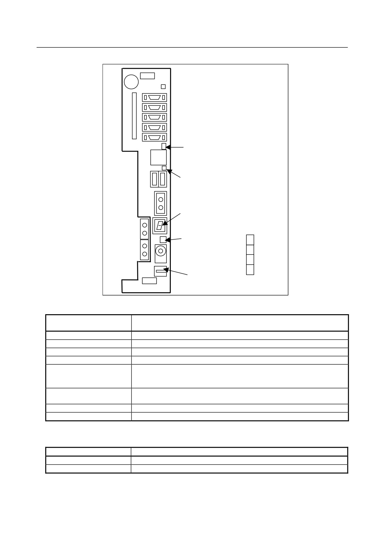
LED display
(2) Status LED for Ethernet
(Embedded Ethernet)
LINK
(Upper, green)
COM
(Lower, yellow)
FUSE ALM : Fuse burn-out detection LED
(red)
(3) STATUS: 7-segment LED
(1) ALARM: Alarm LED
1
(red)
2
3
4
(1) COREALM: Alarm LED (red)
(1) Alarm LED (red LED)
ALM
CORE
Meaning
1
2
3
4
ALM
□
■
□
◇
◇
Low battery voltage. The battery may be is running out.
■
■
□
◇
◇
Software detected an error and stopped the system.
□
□
■
◇
◇
Hardware detected a failure in the system.
■
□
■
◇
◇
An alarm was issued with the servo card on the main board.
□
■
■
◇
◇
An error was detected in the data of the SRAM on the FROM/SRAM module.
The FROM/SRAM module may be faulty, the battery voltage may have dropped, or
the main board may be faulty.
■ ■ ■ ◇
◇
Abnormal power supply operation. The cause may be noise or the back panel (with
power supply) failure.
◇ ◇ ◇ ■
◇
The CPU card may be faulty.
◇ ◇ ◇ ◇
■
Lights if there is an abnormal condition in the power supply on the main board.
■: On
□: Off
◇: Don’t care
(2) Status LED for Ethernet (Embedded Ethernet)
LED
Meaning
LINK (green)
Turned on when a connection is made with the hub correctly.
COM (yellow)
Turned on when data is transferred.
- 202 -
B-64485EN/01
2.CONTROL UNIT HARDWARE
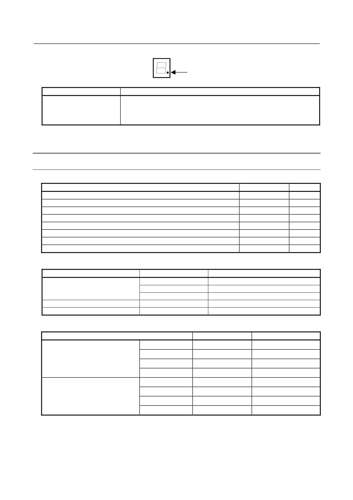
(3)
7-segment LED
Dot
LED
Meaning
Dot
Turned on when the display unit is not connected to connector COP21A.
If this LED is turned on when the display unit is connected, it is probable that the
optical fiber cable is broken, the display unit is not powered on, or the display unit is
faulty.
See Appendix E “LED Display” for others.
2.5.2
Display Unit for Stand-alone Type Control Unit
2.5.2.1 Display Unit (10.4” LCD unit A)
-
Unit specification
Name
Specification
Remark
10.4” LCD unit A
A02B-0323-C074
10.4” LCD unit A (with a protection cover)
A02B-0323-C075
10.4” LCD unit A (with a touch panel)
A02B-0323-C084
10.4” LCD unit A (with a touch panel and protection cover)
A02B-0323-C085
1st 10.4” LCD unit A for two display unit
A02B-0323-C072
1st 10.4” LCD unit A for two display unit (with a protection cover)
A02B-0323-C076
2nd 10.4” LCD unit A for two display unit
A02B-0323-C073
2nd 10.4” LCD unit A for two display unit (with a protection cover)
A02B-0323-C077
-
Prited circuit board for display unit
Name
Specification
Remark
Display control board
A20B-8200-0760
A20B-8200-0761
1st unit for two display unit
A20B-8200-0762
2nd unit for two display unit
Inverter board
A20B-8200-0662
Touch panel control board
A20B-8002-0312
-
Two display unit cable specification
Name
Specification
Remark
30m
A02B-0303-K843
20m
A02B-0303-K840
Interconnection cable for video signal
10m
A02B-0303-K841
5m
A02B-0303-K842
30m
A02B-0303-K848
20m
A02B-0303-K845
Interconnection cable for MDI signal
10m
A02B-0303-K846
5m
A02B-0303-K847
- 203 -
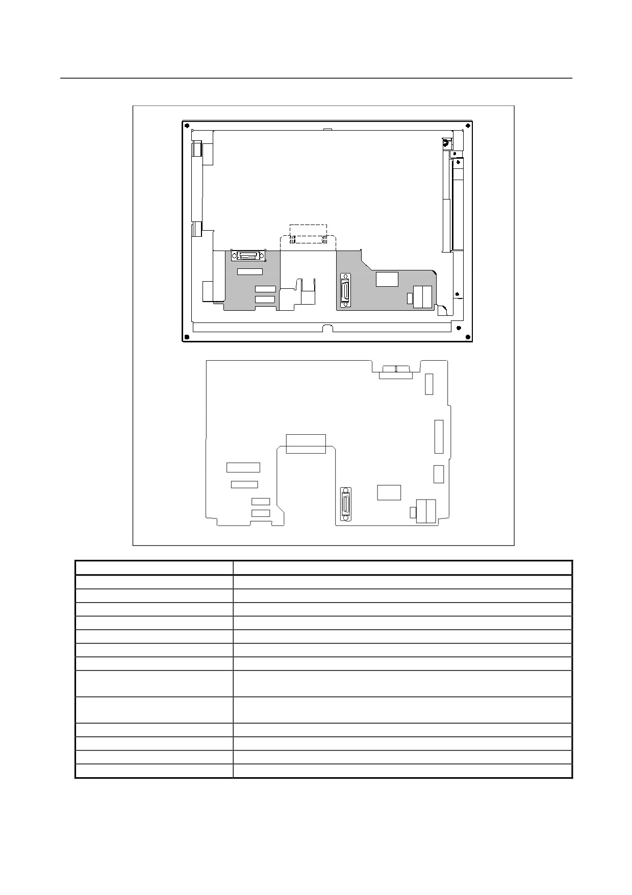
2.CONTROL UNIT HARDWARE
B-64485EN/01
Connector mounting location
Rear view
CA103
JA73
JD36A
CA55
CP1B
CP1A
CK20A
COP21B
CK21A
Fuse
CA132
CA135
Display control board
CA103
CA88A
JA73
CD46A
JD36A
CA55
CP1B CP1A
CK20A
COP21B
CK21A
Fuse
Connector number
Application
CA55
For MDI
JD36A
For touch panel interface
CP1A
For 24VDC power input
CP1B
For 24VDC power output
CA79A
For video signal interface
CA88A
For memory card interface
CD46A
For USB port
CA103
For Interconnection cable for video signal interface (for connecting two display
units)
JA73
For Interconnection cable for MDI signal interface (for connecting two display
units)
CK20A
For horizontal soft key
CK21A
For vertical soft key
CA87A
For inverter board
COP21B
For HSSB interface
- 204 -
B-64485EN/01
2.CONTROL UNIT HARDWARE
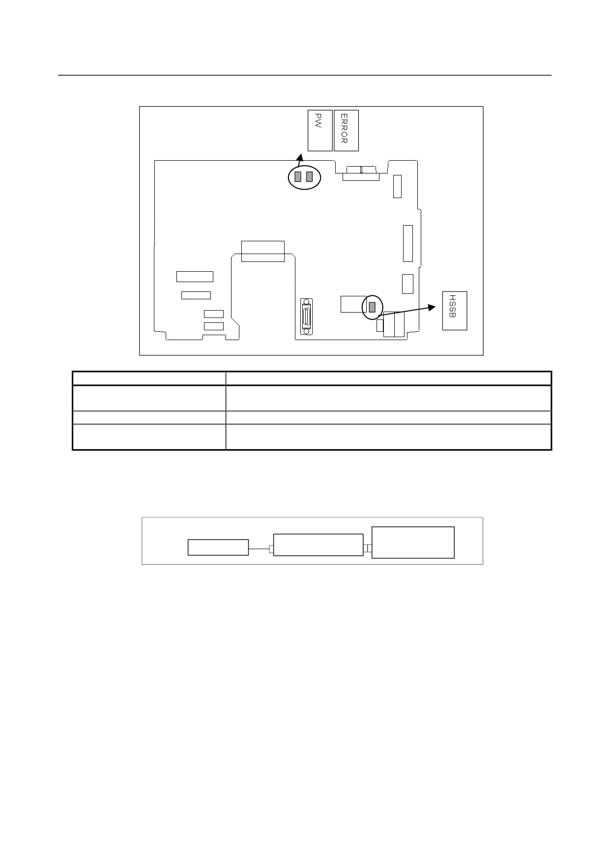
LED display
PW (green)
ERROR (red)
HSSB (green)
LED
Meaning
Lights when this board is normally connected to the control unit and
HSSB (green LED)
communication is enabled.
PW (green LED)
Lights the power is normally turned on.
Lights if the hardware detects a failure in this display unit. It is likely that the
ERROR (red LED)
display control board may be defective.
If a failure is detected on the control unit side, ERROR
(red LED) does not light because of a
communication failure such as a broken HSSB cable. In this case, the screen display that appears when
the failure occurs will keep blinking.
Configuration of the inverter
Display control board
Inverter board
LCD unit
CPA11
CA132
CA132
- 205 -
2.CONTROL UNIT HARDWARE
B-64485EN/01
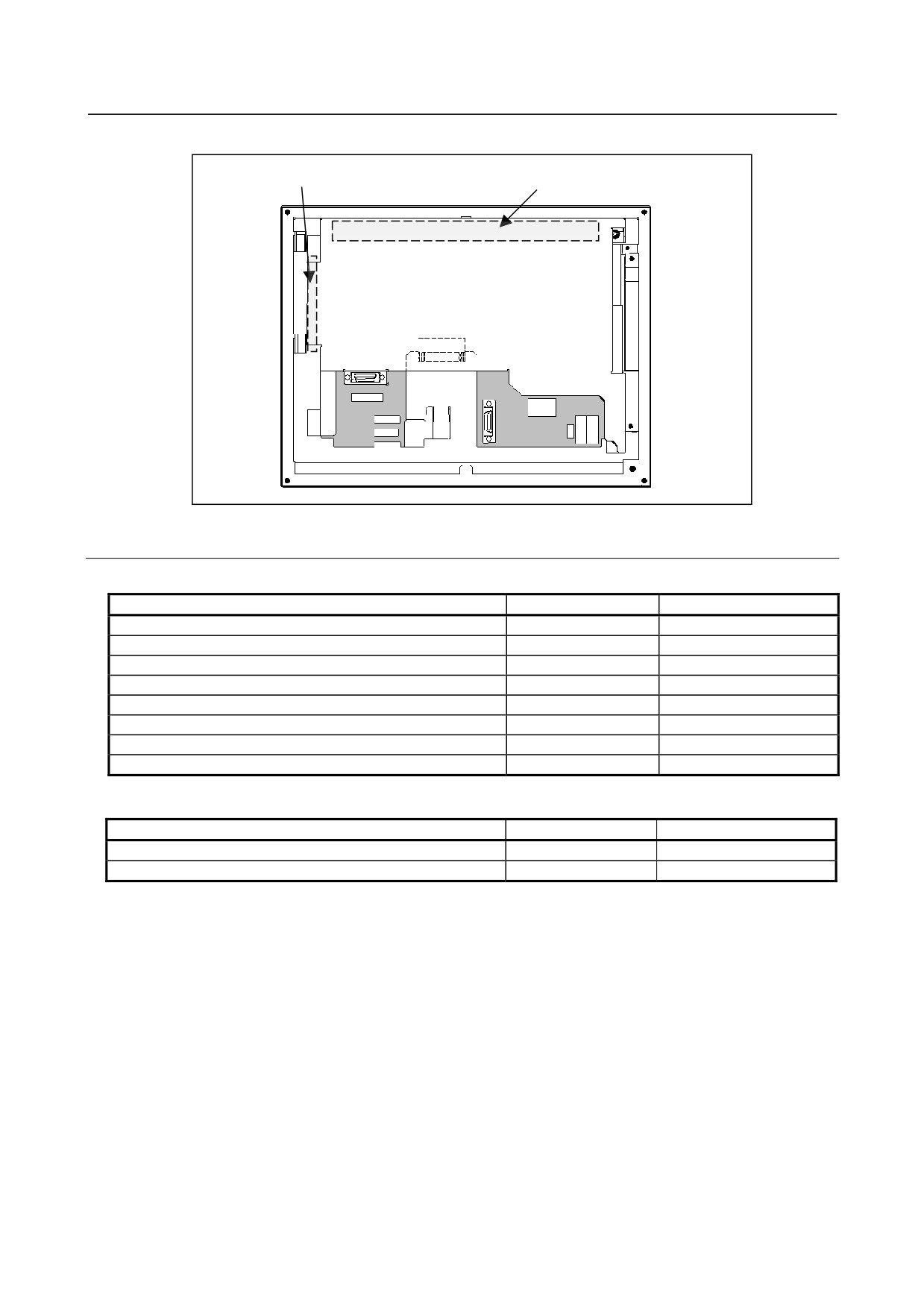
Positions of the inverter board and touch panel printed circuit board
Inverter board
Touch panel printed circuit
2.5.2.2 Display unit (10.4” LCD unit B and 15” LCD unit)
-
Unit specification
Name
Specification
Remark
10.4” LCD unit B
A02B-0323-C078
10.4” LCD unit B (with a touch panel)
A02B-0323-C079
10.4” LCD unit B (with a protection cover)
A02B-0323-C088
10.4” LCD unit B (with a touch panel and protection cover)
A02B-0323-C089
15” LCD unit
A02B-0323-C091
15” LCD unit (with a touch panel)
A02B-0323-C092
15” LCD unit (with a protection cover)
A02B-0323-C095
15” LCD unit (with a touch panel and protection cover)
A02B-0323-C096
-
Display control board specification
Name
Specification
Remark
10.4” LCD unit B
A20B-8200-0746
15” LCD unit
A20B-8200-0742
- 206 -
B-64485EN/01
2.CONTROL UNIT HARDWARE
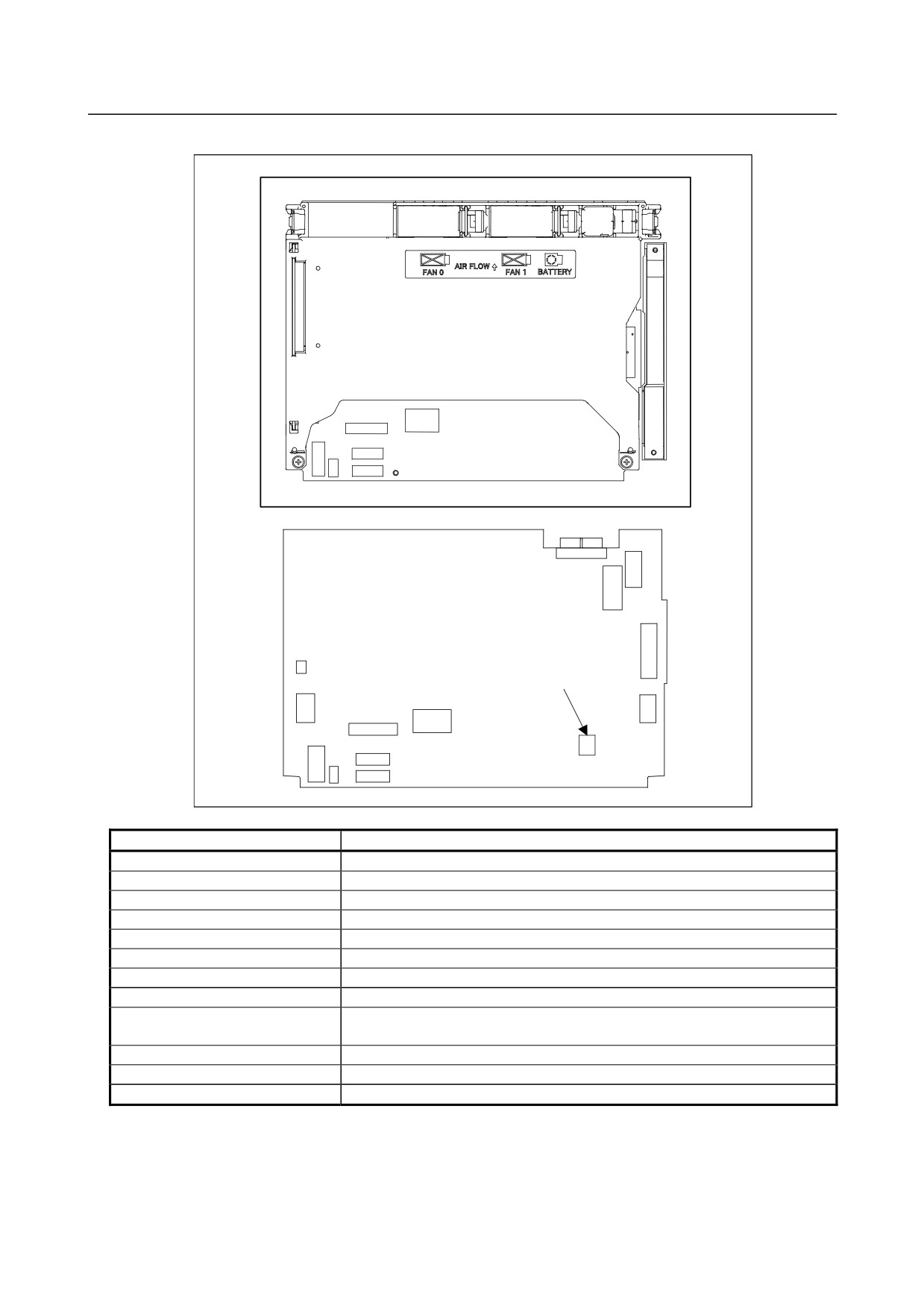
-
Connector mounting location
Rear view
COP21M
CA55
CPD18
CA132
CA135
CA133
CA139
Display control board
CA88A
Rotary switch
CA134
COP21M
CA55
CD46L
CPD18
CK20A
CK21A
Connector number
Application
CA55
For MDI
CPD18
For power supply
CA133
For video signal interface (for 10.4”LCD)
CA135
For video signal interface (for 15”LCD)
CA88A
For memory card interface
CD46L
For USB port
CK20A
For horizontal soft key
CK21A
For vertical soft key
CA132
For inverter board (for 10.4”LCD)
For fan adapter board (for 15”LCD)㩷
COP21M
For HSSB interface
CA139
㪝㫆㫉㩷㫋㫆㫌㪺㪿㩷㫇㪸㫅㪼㫃㩷㫀㫅㫋㪼㫉㪽㪸㪺㪼㩷
CA134
For inverter board (for 15”LCD)
- 207 -
2.CONTROL UNIT HARDWARE
B-64485EN/01
-
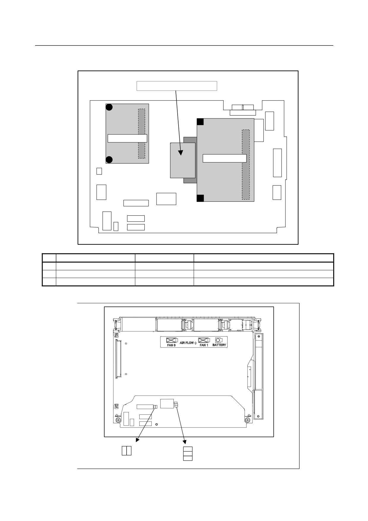
Mounting positions of the GUI card, power supply unit, and compact flash
card
(3) Compact flash card
Connector
Connector
(2) Power supply unit
(1) GUI card
No.
Name
Specification
Remark
(1)
GUI card
A20B-3300-0670
(2)
Power supply unit
A20B-8101-0011
(3)
Compact flash card
A02B-0323-C990#A
Including software
-
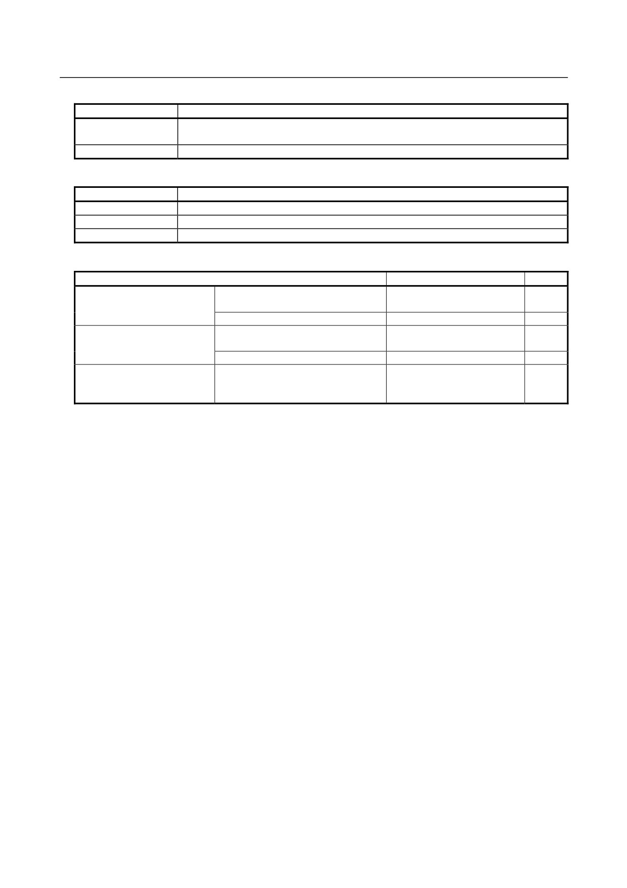
LED display
Rear view
ALM4
BSRDY
DNV8 (green)
(red)
(green)
DNV9 (green)
DNV5 (green)
- 208 -
B-64485EN/01
2.CONTROL UNIT HARDWARE
(1) HSSB status LED
LED
Meaning
Lights when this board is normally connected to the control unit and communication is
BSRDY (green)
enabled.
ALM2 (RAME ⋅ red)
Indicates a common RAM error. It is likely that the display control board may be defective.
(2) Others (green LED)
LED
Meaning
DNV5 (LEDP)
Turned on when power is supplied to the display unit.
DNV8 (LED2)
Indicates the operation status of the screen display function.
DNV9 (LED1)
Indicates the operation status of the screen display function.
-
Inverter board and fan adapter board
Name
Specification
Remark
Inverter board
For 10.4” LCD (working also as fan
A20B-8200-0662
adapter board)
For 15” LCD
A14L-0168-0001
㪝㪸㫅㩷㪸㪻㪸㫇㫋㪼㫉㩷㪹㫆㪸㫉㪻
For 10.4” LCD (working also as fan
Works also as the inverter
adapter board)
board mentioned above.
For 15” LCD
A20B-8200-0669
㪚㫆㫅㫅㪼㪺㫋㫀㫆㫅㩷㪺㪸㪹㫃㪼㩷㪹㪼㫋㫎㪼㪼㫅㩷㫋㪿㪼㩷
For 15” LCD
A660-4042-T076#L75R00
㪻㫀㫊㫇㫃㪸㫐㩷㪺㫆㫅㫋㫉㫆㫃㩷㪹㫆㪸㫉㪻㩷㪸㫅㪻㩷㫋㪿㪼㩷
㫀㫅㫍㪼㫉㫋㪼㫉㩷㪹㫆㪸㫉㪻
- 209 -
2.CONTROL UNIT HARDWARE
B-64485EN/01
-
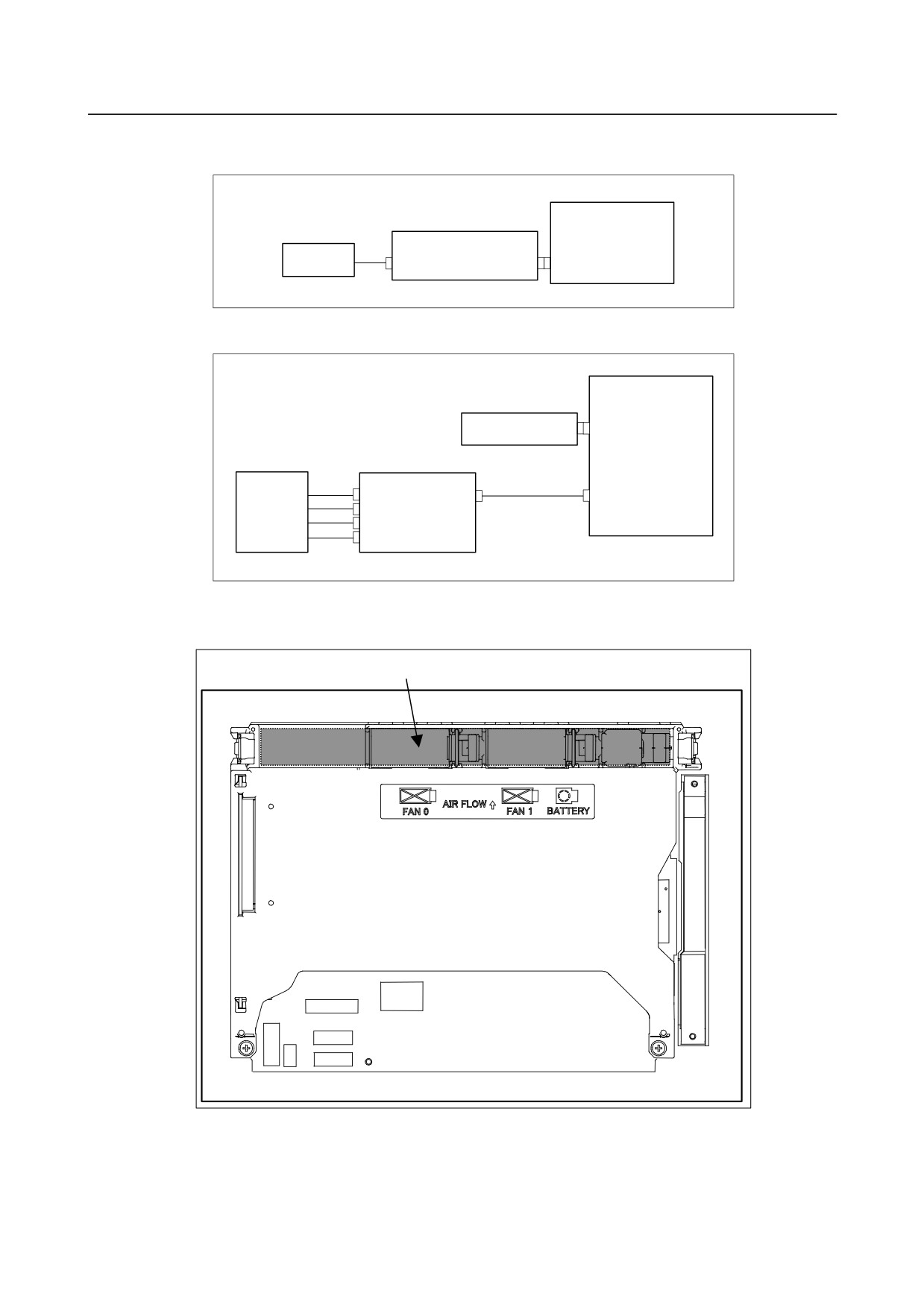
Details of the inverter board
(1) For display unit with 10.4” LCD
Display control board
Inverter board
10.4”LCD unit
(Also functions as a fan adapter board.)
CA132
CP1
CN1
(2) For display unit with 15” LCD
Display control board
Fan adapter board
CA132
CN1
15”LCD unit
Inverter board
CA134
CN02
CN01
Inverter connection cable
CN03
CN04
CN05
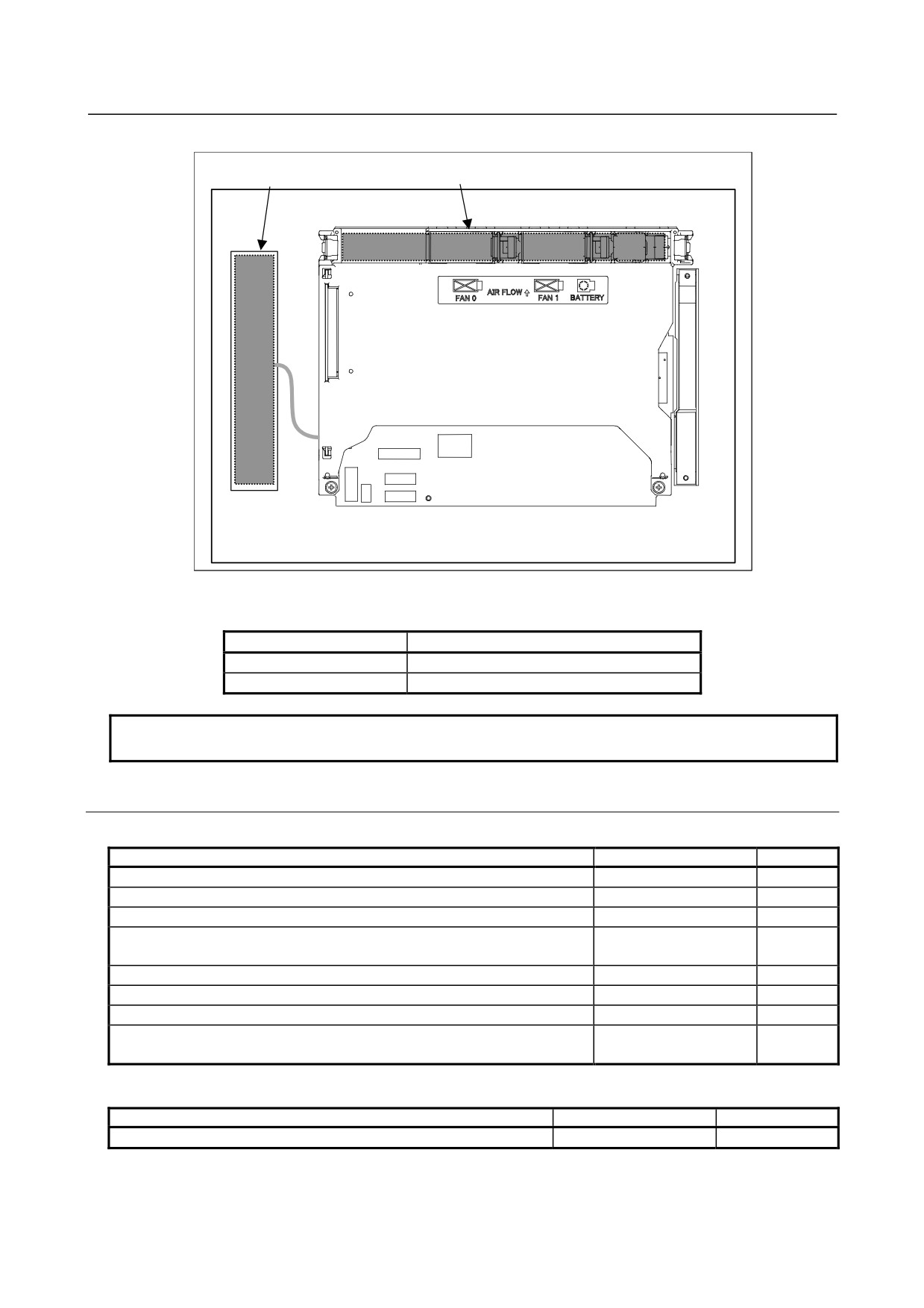
-
Locations of the inverter board and fan adapter board
(1) For display unit with 10.4” LCD
Inverter board
Rear view
- 210 -
B-64485EN/01
2.CONTROL UNIT HARDWARE
(2) For display unit with 15” LCD
Inverter board
Fan adapter board
Rear view
-
Connecting the display unit to the control unit
For the display unit, place the rotary switch to 0 (initial setting).
Connection mode
Rotary switch setting
Default
0
Reserve
1 to F
NOTE
Do not set the rotary switch to the Reserve position.
2.5.2.3 Display unit for automotive manufacture
-
Unit specification
Name
Specification
Remark
Display unit for automotive manufacture
A13B-0201-B201
Display unit for automotive manufacture (with a touch panel)
A13B-0201-B202
Display unit for automotive manufacture (with a protection cover)
A13B-0201-B203
Display unit for automotive manufacture (with a touch panel and protection
A13B-0201-B204
cover)
Display unit for automotive manufacture (with I/O Link)
A13B-0201-B211
Display unit for automotive manufacture (with a touch panel and I/O Link)
A13B-0201-B212
Display unit for automotive manufacture (with I/O Link and protection cover)
A13B-0201-B213
Display unit for automotive manufacture (with a touch panel, I/O Link, and
A13B-0201-B214
protection cover)
-
Display control board
Name
Specification
Remark
Display control board
A20B-8200-0745
- 211 -
2.CONTROL UNIT HARDWARE
B-64485EN/01
-
Display control board mounting location
Rear
view
Display control board
-
Connector mounting location
CA132
CA135
Display control board
CA88A
CA139
Rotary switch
CA134
COP21M
CD46L
CA55
CA117
CPD18
CK20A
CPD15
CK21A
JD54
JD36
Fuse
Connector number
Application
CA55
For MDI
CA132
For fan adapter board
CA88A
For memory card interface
CA139
For touch panel interface
CA135
For video signal interface
CD46L
For USB port
CK20A
For horizontal soft key
CK21A
For vertical soft key
- 212 -
B-64485EN/01
2.CONTROL UNIT HARDWARE
Connector number
Application
COP21M
For HSSB interface
CA134
For inverter board
CPD18
For power supply
JD36
For I/O device interface (RS-232C)
JD54
For I/O device interface (RS-232C) or USB device
CPD15
For DC power interface of the I/O Link adapter board
CA117
For LED interface
-
Mounting positions of the GUI card, power supply unit, and compact flash
card
(3) Compact flash card
Connector
Connector
(2) Power supply unit
(1) GUI card
No.
Name
Specification
Remark
(1)
GUI card
A20B-3300-0670
(2)
Power supply unit
A20B-8101-0011
(3)
Compact flash card
A02B-0323-C990#B
Including software
- 213 -
2.CONTROL UNIT HARDWARE
B-64485EN/01
-
Block diagram
Display control board
GUI card
Display
DRAM
CPU
control
BOOT
software
Compact
Flash card
Peripheral
Peripheral
control 2
control 1
Power supply unit
USB
control
Display unit
HSSB
24VDC
Memory card
USB
: Detachable card or module
- 214 -
B-64485EN/01
2.CONTROL UNIT HARDWARE
-
LED display
Rear view
ALM2
BSRDY
DNV8 (green)
(red)
(green)
DNV9 (green)
DNV5 (green)
(1) HSSB status LED
LED
Meaning
Lights when this board is normally connected to the control unit and communication is
BSRDY (green)
enabled.
ALM2 (RAME ⋅ red)
Indicates a common RAM error. It is likely that the display control board may be defective.
(2) Others (green LED)
LED
Meaning
DNV5 (LEDP)
Turned on when power is supplied to the display unit.
DNV8 (LED2)
Indicates the operation status of the screen display function.
DNV9 (LED1)
Indicates the operation status of the screen display function.
- 215 -
2.CONTROL UNIT HARDWARE
B-64485EN/01
ABC
CAPS
(green)
LOCK
(green)
POWER CARD
STATUS
(green)
(green)
(red) (green)
Key board
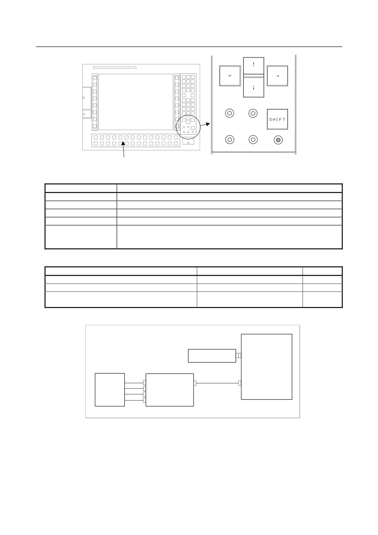
(4) LED on MDI
LED
Meaning
ABC (green)
Lights when the function key is in the alphabet input mode.
CAPS LOCK (green)
Lights when CAPS LOCK is enabled.
POWER (green)
Lights when the unit is powered on.
CARD (green)
Lights when data is being written to or read from the built-in memory card.
Lights in red during power-on or in green when after startup.
STATUS (green / red)
Normally, this LED lights in green, but lights in red if a hardware alarm such as
overheating, fan stop, or bus disconnection occurs.
-
Inverter board and fan adapter board
Name
Specification
Remark
Inverter board㩷
A14L-0168-0001
Fan adapter board
A20B-8200-0669
Connection cable between the display control board and
A660-4042-T076#L75R00
the inverter board
-
Details of the inverter board
Display control board
Fan adapter board
CA132
CN1
LCD unit
Inverter board
CA134
CN02
CN01
Inverter connection cable
CN03
CN04
CN05
- 216 -
B-64485EN/01
2.CONTROL UNIT HARDWARE
-
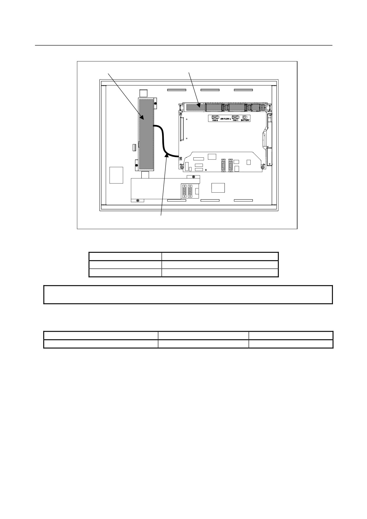
Locations of the inverter board and fan adapter board
Inverter board
Fan adapter board
Rear view
Connection cable between the display control board and the inverter board
-
Connecting the display unit to the control unit
For the display unit, place the rotary switch to 0 (initial setting).
Connection mode
Rotary switch setting
Default
0
Reserve
1 to F
NOTE
Do not set the rotary switch to the Reserve position.
I/O Link adapter board (Unit specification: A13B-0201-B211, -B212, -B213, and
-B214 only)
Name
Specification
Remark
I/O Link adapter board㩷
A20B-8002-0500
- 217 -
2.CONTROL UNIT HARDWARE
B-64485EN/01
-
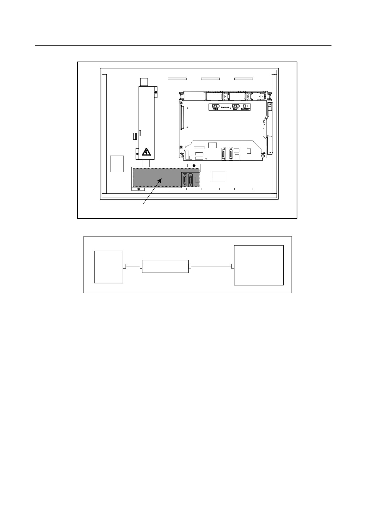
I/O Link adapter board mounting location
Rear view
I/O Link adapter board
-
Details of the I/O Link adapter board
Display control board
LCD unit
I/O Link adapter board
CPD15
CK33
CPD15
Power supply cable
(A660-2005-T779#L160R0)
Use of NCBOOT32
1.
Purpose
NCBOOT32 perform the following operations.
• Displays the BOOT screen.
On this screen, it is possible to perform CNC maintenance work such as installation or backup of the
CNC system program or saving, restoration, or clearing of SRAM.
• Displays the IPL screen.
• Displays the CNC alarm screen.
• Monitors the state of communication with the CNC and makes reconnection during occurrence of an
error.
2.
Startup
Using the rotary switch on the display control board in the display unit for automobile manufacturers can
change the startup sequence.
To start NCBOOT32 or return to the normal operation, turn off the power, change the position of the
rotary switch, and turn on the power again.
(1) Rotary switch position in normal operation: 0
1.
The CNC and display unit wait for communication to be established.
2.
The system waits for the battery to be charged completely (only when the battery unit is
enabled).
3.
The system monitors a communication error and CNC system alarm.
- 218 -
B-64485EN/01
2.CONTROL UNIT HARDWARE
(2) Rotary switch position during startup of NCBOOT32 (during maintenance): F
1.
The CNC and display unit wait for communication to be established.
2.
The system displays the BOOT screen.
3.
The system displays the IPL screen.
4.
The system displays the CNC power-on screen.
5.
The system monitors a communication error and CNC system alarm.
3.
Descriptions of the BOOT and IPL screens
The operating procedure for the BOOT and IPL screens on the display unit for automobile manufacturers
is the same as for the personal computer function with Windows® CE.
See Appendix F.3 for the descriptions of the operating procedure.
2.5.3
Display Unit for Stand-Alone Type Control Unit (with Personal
Computer Function with Windows®CE)
-
Display control board specification
Name
Specification
Remark
Display control board (for 10.4"LCD)
For A13B-0201-B001,-B003,-B004, and -B006
A20B-8200-0740
Display control board (for 12.1”LCD)
For A13B-0201-B011,-B013,-B014, and -B016
A20B-8200-0743
Display control board (for 15”LCD)
For A13B-0201-B021,-B023,-B024, and -B026
A20B-8200-0741
- 219 -
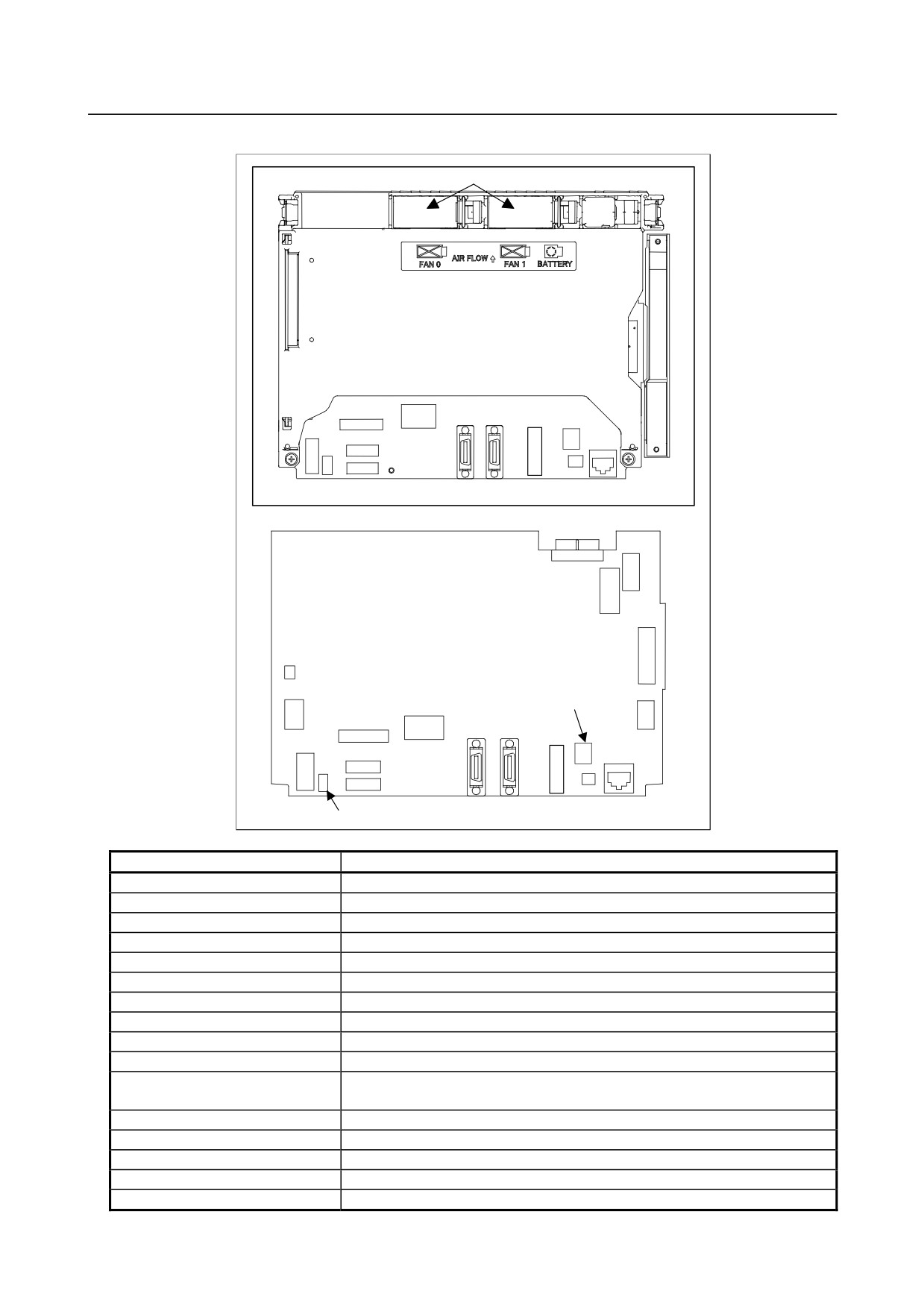
2.CONTROL UNIT HARDWARE
B-64485EN/01
-
Connector mounting location
Fan motor
Rear view
CA55
COP21M
CA136
CPD18
JD54
JD36
CA76
CD38S
CA132
CA135
CA133
CA139
Display control board
CA88A
CA134
Rotary switch
COP21M
CD46L
CA55
CA136
CPD18
CD38S
CK20A
CK21A
JD54
JD36
CA76
Fuse
Connector number
Application
CA55
For MDI
JD36
For I/O device interface (RS-232C)
JD54
For I/O device interface (RS-232C) or USB device
CPD18
For power supply
CA133
For video signal interface (for 10.4”/12.1” display unit)
CA135
For video signal interface (for 15” display unit)
CA88A
For memory card interface
CD46L
For USB port
CK20A
For horizontal soft key
CK21A
For vertical soft key
CA132
For inverter board (for 10.4” display unit)
For fan adapter board (for 12.1”/15” display unit)
COP21M
For HSSB interface
CD38S
For Ethernet (Windows CE control)
CA139
For touch panel interface
CA134
For inverter board (for 12.1”/15” display unit)
CA76
For buzzer interface
- 220 -
B-64485EN/01
2.CONTROL UNIT HARDWARE
Connector number
Application
CA136
㪝㫆㫉㩷㪹㪸㪺㫂㫌㫇㩷㫌㫅㫀㫋㩷
-
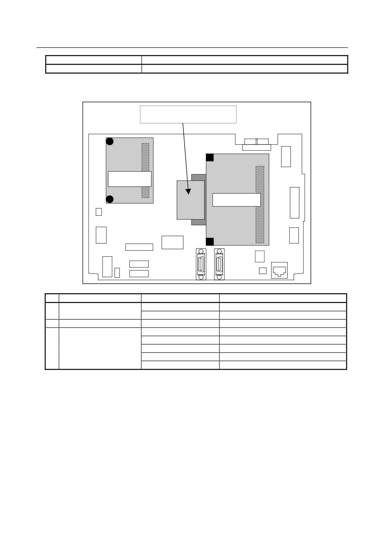
Mounting positions of the GUI card, power supply unit, and compact flash
card
(3) Compact flash card
Connector
Connector
(2) Power supply unit
(1) GUI card
No.
Name
Specification
Remark
(1)
GUI card
A20B-3300-0670
A20B-3300-0671
(2)
Power supply unit
A20B-8101-0011
(3)
Compact flash card
A87L-0001-0173#128MBD
Total capacity: 128MB
A87L-0001-0173#256MBD
Total capacity: 256MB
A87L-0001-0173#512MBD
Total capacity: 512MB
A87L-0001-0173#001GBD
Total capacity: 1GB
A87L-0001-0173#002GBD
Total capacity: 2GB
- 221 -