FANUC Series 30i-MODEL B, 31i-MODEL B, 32i-MODEL B. MAINTENANCE MANUAL - page 6
1.DISPLAY AND OPERATION
B-64485EN/01
Column
Line
<1>
<2>
<3>
<4>
<5>
<6>
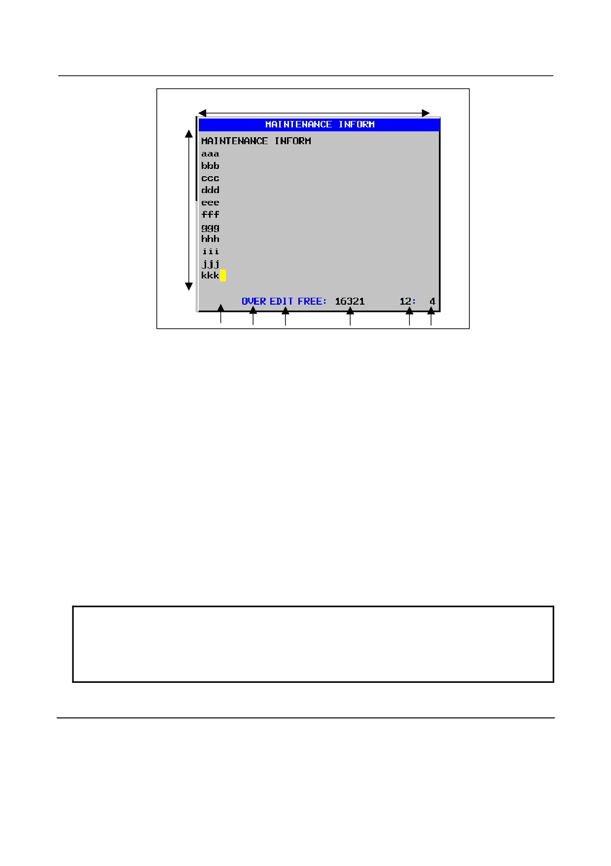
Fig. 1.10.1 (a) MAINTENANCE INFORMATION screen
Status display
<1> Kana/alphabetic
KN: Half-size kana input mode.
ABC: English input mode
<2> OVER / INSERT
OVER: Overwrite mode
INSERT: Insert input mode.
<3> EDIT / READ
EDIT: Editing allowed
READ: Editing inhibited
<4> Number of empty character spaces
Number of empty character spaces as half-size characters
<5> Current cursor line
Position of the line on which the cursor is currently located.
<6> Current cursor column
Position of the column at which the cursor is currently located.
NOTE
The numbers of lines and columns that can be displayed by each LCD are:
•
10.4” display unit: 37 characters × 12 lines
•
8.4” display unit: 38 characters × 11 lines
•
15” display unit: 38 characters × 19 lines
1.10.2 Operating the Maintenance Information Screen
The maintenance information screen has view mode and edit mode, which are selected by pressing the
soft key [END] or [EDIT].
Initially, view mode is selected. To start editing, select edit mode by pressing the soft keys [(OPRT)] and
[EDIT]. When the editing is completed, press the soft key [END] key. Then, select soft key [SAVE] or
[QUIT]. Unless soft key [SAVE] is selected, the edited data will be lost at next power-up.
- 132 -
B-64485EN/01
1.DISPLAY AND OPERATION
To scroll the screen showing the recorded information, press a cursor keys or page keys on the MDI
panel.
The following keys are used for editing (character input) and viewing:
Table 1.10.2 (a) Table of (edit) operations on the maintenance information screen
Mode
Key
Description
View
Soft key
[EDIT]
Allows editing.
[JUMP]
Displays the beginning or the end.
Cursor keys
Scrolls the screen up or down.
Page keys
Scrolls the screen up or down in units of whole screens.
Edit
Soft key
[END]
Ends editing. Select whether to save the edited data.
[KN/ABC]
Switches between half-size kana input and alphabetic input modes.
(Supports Japanese display only.)
[CLEAR ALL]
Clears all maintenance information. (This key is enabled when the bit 7
(MDC) of parameter No. 3116 is set to 1.)
[I/O]
Reads or punches the maintenance information.
[JUMP]
Moves the cursor to the beginning or end.
Cursor keys
Moves the cursor position up or down.
Page keys
Scrolls the screen up or down in units of whole screens.
Alphanumeric/ special
Allows alphabetical, numeric, or special character input. (For details of
character keys
half-size kana input, see Item, " Half-size kana input".)
key
Switches between insert and overwrite modes.
• If the key input buffer does not contain any character, deletes the one
character at the cursor position.
key
• If the key input buffer contains characters, deletes the characters from the
buffer.
• If the key input buffer does not contain any character, deletes the one
character before the cursor.
key
• If the key input buffer contains characters, deletes the one character from
the buffer.
• If the key input buffer does not contain any character, starts a new line.
key
• If the key input buffer contains characters, outputs the characters from the
buffer to the information screen.
1.10.3
Half-Size Kana Input on the Maintenance Information Screen
By pressing soft key [KN/ABC], you can switch between half-size kana input and alphabetic input
modes.
In half-size kana input mode, alphabetic characters are converted in accordance with the "half-size
kana/Roman character conversion table" and resultant half-size kana characters are displayed in the key
input buffer.
Pressing the
key causes the characters in the key input buffer to be output to maintenance
information.
Pressing the
key causes the characters to be deleted from the key input buffer and the one
character of the maintenance information on which the cursor is positioned to be deleted.
Pressing the
key causes cancels conversion, and deletes one character from the key input buffer. If
the key input buffer does not contain any character, the one character of the maintenance information that
immediately precedes the cursor is deleted.
- 133 -
1.DISPLAY AND OPERATION
B-64485EN/01
1.10.4 Warnings That Occurs on the Maintenance Information
Screen
The following warnings occur on the maintenance information screen.
Warning message
Meaning
NO MORE SPACE
An overflow occurred in CNC memory.
ALARM
The operation could not be performed because an alarm was
generated in the CNC.
BUSY
Wait for CNC processing to end or make a retry.
ILLEGAL DATA
Investigate data and correct it as required.
WRONG MODE
The CNC is in wrong mode.
COMMAND ILLEGAL USE
A corresponding CNC option cannot be found.
PARAMETER ERROR
CNC parameter settings contain an error.
EDIT REJECTED
An attempt was made to perform an edit operation on data that could
not be edited.
WRITE PROTECT
Writing is prohibited.
COMMAND REJECT
The CNC rejected the execution of the processing. Check the
execution conditions.
1.10.5 Parameter
#7
#6
#5
#4
#3
#2
#1
#0
3116
MDC
[Input type] Setting input
[Data type] Bit path
#7 MDC Maintenance information data:
0: Cannot be erased entirely.
1: Can be erased entirely.
#7
#6
#5
#4
#3
#2
#1
#0
3206
MIF
[Input type] Parameter input
[Data type] Bit
#1 MIF Editing of the maintenance information screen is:
0: Not prohibited.
1: Prohibited.
#7
#6
#5
#4
#3
#2
#1
#0
8901
MEN
[Input type] Setting input
[Data type] Bit path
#7 MEN The periodic maintenance screen is:
0: Displayed.
1: Not displayed.
- 134 -
B-64485EN/01
1.DISPLAY AND OPERATION
1.10.6 Overview of the History Function
It is possible to record history of operations performed by the operator, alarms that occurred, external
operator messages, etc. in order to check the history or output history data.
1
Conditions under which history is recorded
a
Display screen
History is recorded when a screen other than the operation history screen is displayed.
b Signal selection
Up to 60 input/output signals for which history is recorded can be selected.
c
Parameter setting
It is possible to set parameters in order to specify individually whether to record data change
history such as operation history of the MDI key, history of external operator messages,
addition of external alarms/messages, parameters/tool offset, workpiece offset (workpiece shift
amount)/custom macro common variable, operation history of input/output signals.
d Storage capacity
When the storage capacity is exhausted, data is deleted in the chronological order, oldest first.
A maximum of approximately 8000 history items can be recorded when, for example, only the
operation history of the MDI key is stored.
2
Data output
All the history data items stored can be output to an external input/output unit (see the section about
outputting of all history data).
3
Deletion of history
When bit 7 (EKE) of parameter No. 3195 is 1, soft key [ALL CLEAR] appears, which can be used
to delete history data.
#7
#6
#5
#4
#3
#2
#1
#0
3195
EKE
[Data type] Bit
#7 EKE The [ALL CLEAR] soft key for clearing all history data is:
0: Not displayed.
1: Displayed.
NOTE
1 History data is not cleared even after power-off.
If memory clear operation is performed, however, history data is also deleted.
2 The correct date and time need to be set on the setting screen.
3 All history data items including alarms, external operator messages, operations,
and input/output signals are integrated into one and stored in a single storage
area. Therefore, when the storage capacity is exhausted, data is deleted in the
chronological order, oldest first, regardless of the type of history.
The deletion of history data deletes all history data, so care should be executed
before performing deletion.
Delete operation cannot be performed on a per-history-type basis.
- 135 -
1.DISPLAY AND OPERATION
B-64485EN/01
1.10.6.1 Alarm history
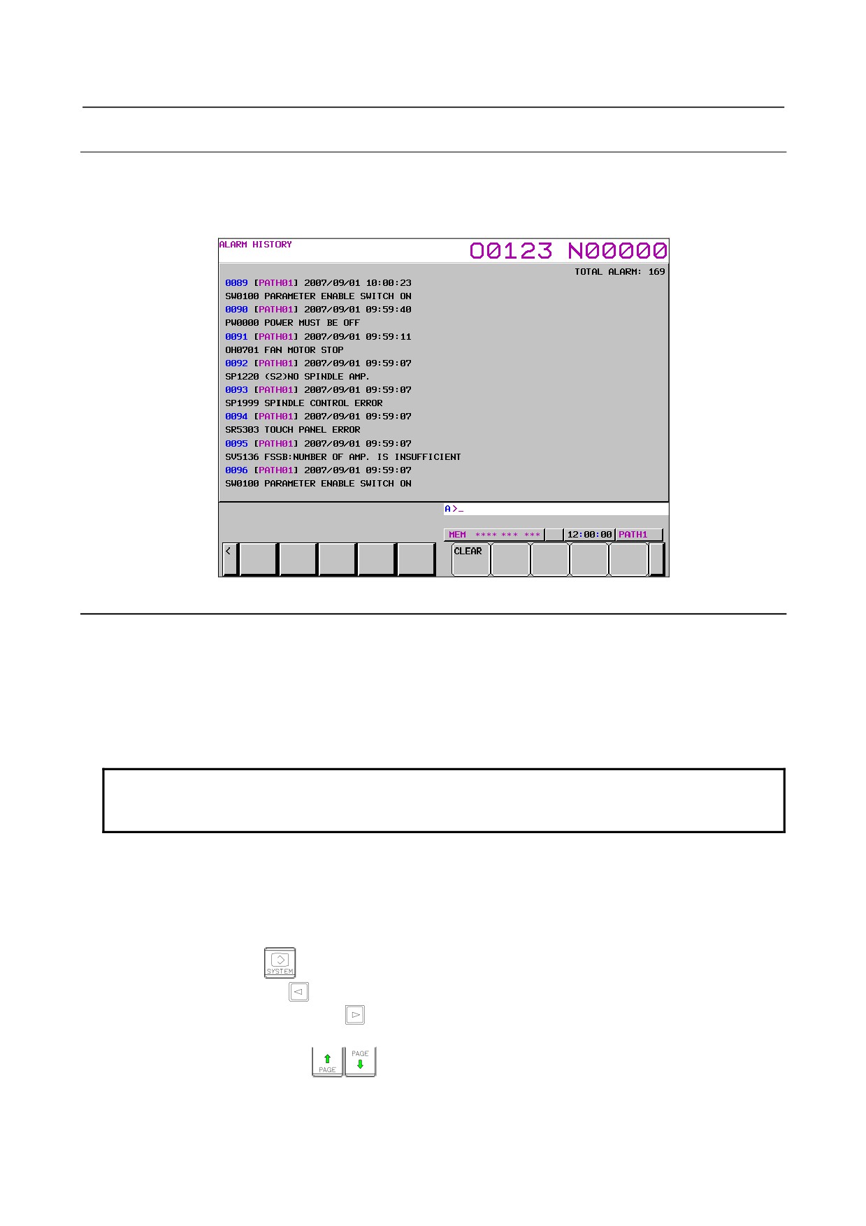
Only alarm history is extracted from all history data recorded and displayed on the screen. When the
amount of history data exceeds the storage capacity, data is automatically deleted in the chronological
order, oldest first.
Fig. 1.10.6.1 (a) Alarm history screen
Screen display
The alarms that occurred are displayed in the chronological order, most recent first.
The following items are indicated for each alarm.
Path name (only for multi-path operation)
Date and time of alarm issuance
Alarm type and number
Alarm message
NOTE
To record external alarm and macro alarm messages as history data, set bit 3
(EAH) of parameter No. 3112 to 1 and bit 7 (HAL) of parameter No. 3196 to 0.
If the path name, axis name, or spindle name is changed after occurrence of an alarm, the new name is
displayed on the alarm history screen.
For modal 'O' data, only the first five characters are output in the case of the program name.
-
Procedure
1
Press function key
to display the screen for parameters etc.
2
Press return menu key
3
Press the continuous menu key
several times until soft key [HISTORY] is displayed.
4
Press soft key [HISTORY] to display the alarm history screen.
5
Press page switching keys
to move between the previous page and the next page.
- 136 -
B-64485EN/01
1.DISPLAY AND OPERATION
Deleting history data on the alarm history screen
-
Procedure
1
Display the alarm history screen.
2
Press the soft key [(OPRT)].
3
If soft key [(CLEAR)] is pressed, all history data is deleted.
NOTE
The delete operation deletes not only alarm history, but also external operator
message history, operation history, and other history data. Delete operation
cannot be performed on a per-history-type basis.
Holding alarm history
Alarm history is held in the same storage area as in other history data such as key operation history and
signal change history. Therefore, alarm history is deleted when the storage capacity is fully exhausted by
other history data.
When bit 2 (SAH) of parameter No. 11354 is set to 1, alarm history data is stored in the area specific to
alarm history and recorded in the storage area for operation history. Accordingly, up to 50 alarm history
items can be held even if the storage capacity is fully exhausted by other history data.
However, additional information (modal data, absolute coordinates, and machine coordinates during
occurrence of an alarm) is not recorded in the area specific to alarm history. (The additional information
is recorded in the storage area of operation history.)
Deleting alarm history
If history is deleted on the alarm history screen when bit 2 (SAH) of parameter No. 11354 is set to 1, only
the alarm history is deleted. Even if history is deleted on the operation history screen or external operator
message screen, alarm history is not deleted.
Parameter setting
#7
#6
#5
#4
#3
#2
#1
#0
11354
SAH
[Data type] Bit
#2 SAH When the storage capacity for history data is exceeded due to non-alarm history, alarm
history will be:
0: Erased.
1: Erased, except the most recent 50 items of history data.
Displaying an external alarm or macro alarm
When an external alarm or macro alarm is caused by setting the following parameters, the message in
addition to the alarm number can be recorded in alarm history.
#7
#6
#5
#4
#3
#2
#1
#0
3112
EAH
[Data type] Bit
#3 EAH Messages of the external alarm/macro alarm in alarm or operation history:
0: Not recorded
1: Recorded
- 137 -

1.DISPLAY AND OPERATION
B-64485EN/01
NOTE
This parameter is valid when bit 7 (HAL) of parameter No. 3196 is
set to 0.
#7
#6
#5
#4
#3
#2
#1
#0
3196
HAL
[Input type] Parameter input
[Data type] Bit
#7 HAL When an alarm is issued, additional information (modal data, absolute coordinates, and
machine coordinates present at the issuance of the alarm) is:
0: Recorded in the operation history and alarm history.
1: Not recorded in the operation history and alarm history.
NOTE
1 Since alarms, operations, external operator messages, and data
change history are held in the same storage area, alarm history
may be deleted if the storage capacity is fully exhausted by other
history data.
2 The maximum number of history items that can be recorded is
shown below (when the history items are alarms).
When bit 7 (HAL) of parameter No. 3196 is 1, the maximum
number is approximately 4000.
When bit 7 (HAL) of parameter No. 3196 is 0, the maximum
number depends on the system because the modal information
and coordinates during occurrence of an alarm are also recorded.
(Example: 280 for 5-axis systems and 200 for 10-axis systems)
When bit 3 (EAH) of parameter No. 3112 is 1, however, messages
for macro alarms and external alarms are also recorded, the
maximum number is further reduced.
1.10.6.2 External operator message history
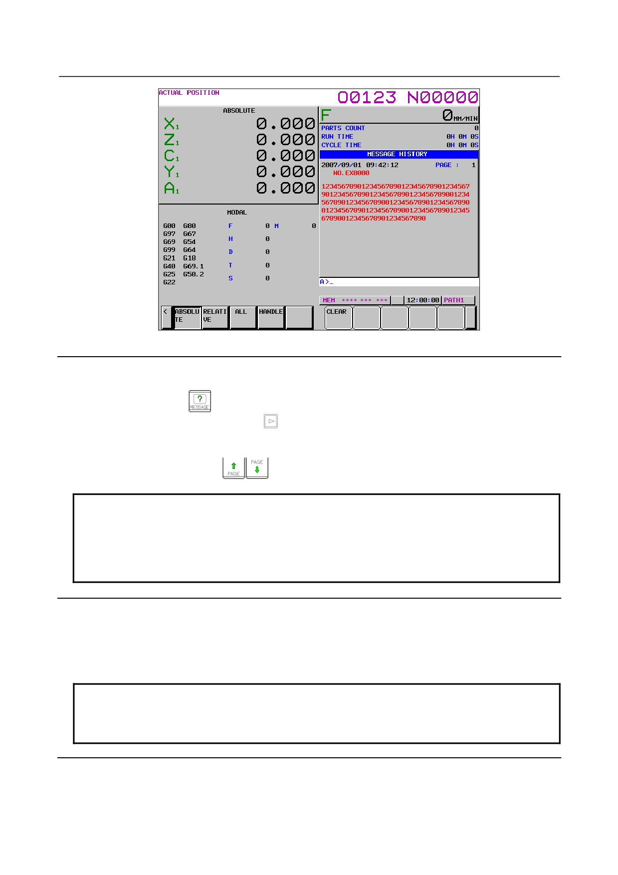
Only external operator message history and macro message history are extracted from all history data
recorded and displayed on the screen. When the amount of history data exceeds the storage capacity, data
is automatically deleted in the chronological order, oldest first.
- 138 -
B-64485EN/01
1.DISPLAY AND OPERATION
Fig. 1.10.6.2 (a) External operator message history screen
Screen display
-
Procedure
1
Press function key
2
Press the continuous menu key
several times until soft key
[MESSAGE HISTRY]]
is
displayed.
3
Press soft key [MESSAGE HISTRY]] to display the external operator message history screen.
4
Press page switching keys
to move between the previous page and the next page.
NOTE
1 Since external operator messages, operations, alarms, and data change history
are held in the same storage area, external operator message history may be
deleted if the storage capacity is fully exhausted by other history data.
2 The maximum number of history items that can be recorded is approximately
150 (when the history items are external operator messages).
Deleting history data from the external operator message history screen
-
Procedure
1
Display the external operator message history screen.
2
Press the soft key [(OPRT)].
3
If soft key [CLEAR] is pressed, all history data is deleted.
NOTE
The delete operation deletes not only external operator message history, but
also operation history, alarm history, and other history data. Delete operation
cannot be performed on a per-history-type basis.
Holding external operator message history
External operator message history is held in the same storage area as in other history data such as key
operation history and signal change history. Therefore, external operator message history is deleted when
the storage capacity is fully exhausted by other history data.
- 139 -
1.DISPLAY AND OPERATION
B-64485EN/01
When bit 3 (SOH) of parameter No. 11354 is set to 1, external operator message history data is stored in
the area specific to external operator message history and recorded in the storage area for operation
history. Accordingly, external operator message history items can be held even if the storage capacity is
fully exhausted by other history data.
Deleting external operator message history
If history is deleted on the external operator message history screen when bit 3 (SOH) of parameter No.
11354 is set to 1, only the external operator message history is deleted. Even if history is deleted on the
operation history screen or alarm history screen, external operator message history is not deleted.
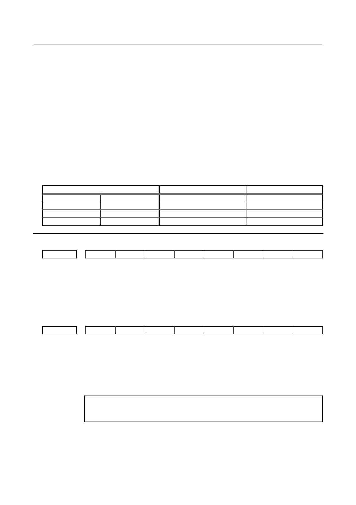
Number of characters in external operator message history and number of
external operator messages
When bit 3 (SOH) of parameter No. 11354 is set to 1, the number of characters in external operator
message history and the number of external operator messages are set by bit 6 (MS0) and bit 7 (MS1) of
parameter No. 3113. The correspondence between the settings, the number of characters, and the number
of messages is shown in Table 1.10.6.2 (a).
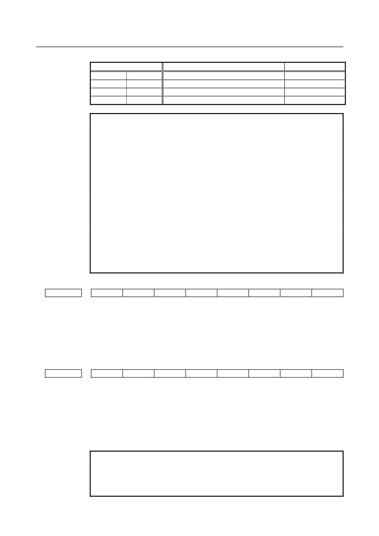
Table 1.10.6.2 (a)
Parameter
Maximum number of characters
Number of messages
MS0=0
MS1=0
255
8
MS0=1
MS1=0
200
10
MS0=0
MS1=1
100
18
MS0=1
MS1=1
50
32
Parameter setting
#7
#6
#5
#4
#3
#2
#1
#0
3112
OMH
[Input type] Parameter input
[Data type] Bit
#2 OMH The external operator message history screen is:
0: Not displayed.
1: Displayed.
#7
#6
#5
#4
#3
#2
#1
#0
3113
MS1
MS0
HMC
[Input type] Parameter input
[Data type] Bit
#0 HMC The contents of the external operator message history:
0: Cannot be erased.
1: Can be erased.
NOTE
This parameter is valid when bit 3 (SOH) of parameter No. 11354 is
set to 1.
#6
MS0
#7
MS1 Set the combination of the number of characters and the number of messages to be
preserved in the external operator message history.
- 140 -
B-64485EN/01
1.DISPLAY AND OPERATION
Table 1.10.6.2 (b)
Parameter
Maximum number of characters
Number of messages
MS0=0
MS1=0
255
8
MS0=1
MS1=0
200
10
MS0=0
MS1=1
100
18
MS0=1
MS1=1
50
32
NOTE
1 Although up to 255 characters can be specified for each external
operator message, you can use the combination of bits 6 (MS0)
and 7 (MS1) of parameter No. 3113 to limit the number of
characters and select the number of messages to be preserved in
the external operator message history.
2 The settings of bits 6 (MS0) and 7 (MS1) of parameter No. 3113
take effect the next time the power is turned on. The external
operator message history is erased at that time.
3 Even though you change the settings of bits 6 (MS0) and 7 (MS1)
of parameter No. 3113, the alarm PW0000, "POWER MUST BE
OFF" is not issued. You must however turn on the power again
before the new settings can take effect.
4 If text (such as single-byte katakana or kanji characters) is entered
in character code, the number of characters recorded in the
external operator message history may be smaller than the
maximum number of characters set by bits 6 (MS0) and 7 (MS1) of
parameter No. 3113.
#7
#6
#5
#4
#3
#2
#1
#0
3196
HOM
[Input type] Parameter input
[Data type] Bit
#6 HOM A history of external operator messages and macro messages ((#3006) is:
0: Recorded.
1: Not recorded.
#7
#6
#5
#4
#3
#2
#1
#0
11354
SOH
[Input type] Parameter input
[Data type] Bit
#3 SOH When the storage capacity for history data is exceeded due to data other than external
operator message history, external operator message history will be:
0: Erased.
1: Retained.
NOTE
1 The setting of bit 3 (SOH) of parameter No. 11354 will be effective
the next time the power is turned on. At this time, all history data
(operation history, alarm history, and external operator message
history) will be erased.
- 141 -

1.DISPLAY AND OPERATION
B-64485EN/01
NOTE
2 When bit 3 (SOH) of parameter No. 11354 is set to 1, the number
of history data items that can be retained varies. The number of
history data items that can be recorded as follows:
Bit 3 (SOH) of parameter No. 11354=0 . . . Approx. 8000 items
Bit 3 (SOH) of parameter No. 11354=1 . . . Approx. 7500 items
(*) The numbers of items above are those if only key operation
history is recorded.
1.10.6.3 Operation history
This function displays the history of key-in and signal operation performed by the operator when a failure
or alarm occurs and the history of an alarm that occurred.
What is recorded is shown below.
a
Operation history
i
MDI key operation by the operator
ii
Turning on or off of output signals (X, Y, G, F)
b Alarm history
i
Alarm that occurred
ii
Modal information and coordinates of the block executed during occurrence of an alarm
(Not displayed on the screen.)
c
Data change history
i
Change of tool offset data
(When the bit 0 (HTO) of parameter No. 3196 is set to 1)
ii
Change of workpiece offset data/extended workpiece offset data/workpiece shift amount (T
series)
(When the bit 1 (HWO) of parameter No. 3196 is set to 1)
iii
Change of a parameter
(When the bit 2 (HPM) of parameter No. 3196 is set to 1)
iv Change of custom macro common variable data
(When the bit 3 (HMV) of parameter No. 3196 is set to 1)
d External operator message history and macro message history
(When the bit 6 (HOM) of parameter No. 3196 is set to 0)
e
Time stamp (date/time)
History data of operation history and alarm history except certain parts can be referenced on the operation
history screen. (Data change history, external operator message history, and alarm messages are not
displayed.)
All of recorded history data can be output to external input/output units.
NOTE
The maximum number of items that can be recorded is approximately 8000
when the items are assumed to be MDI key operation history. Since each history
data size is not constant, however, the maximum number varies.
Parameter setting
#7
#6
#5
#4
#3
#2
#1
#0
3106
OPH
#4 OPH The operation history screen is:
0: Not displayed.
1: Displayed.
- 142 -
B-64485EN/01
1.DISPLAY AND OPERATION
3122
Time interval used to record time data in operation history
[Input type] Parameter input
[Data type] Word
[Unit of data] min
[Valid data range] 0 to 1440
Time data is recorded in operation history at specified time intervals.
When 0 is set, the specification of a time period of 10 minutes is assumed.
If data to be recorded is not present within the time period, no time data is recorded.
NOTE
This parameter must be set to the same value for all paths.
#7
#6
#5
#4
#3
#2
#1
#0
3195
EKE
HDE
HKE
[Input type] Parameter input
[Data type] Bit
#5 HKE A key operation history is:
0: Recorded.
1: Not recorded.
#6 HDE A DI/DO history is:
0: Recorded.
1: Not recorded.
#7 EKE The [ALL CLEAR] soft key for clearing all history data is:
0: Not displayed.
1: Displayed.
#7
#6
#5
#4
#3
#2
#1
#0
3196
HAL
HOM
HMV
HPM
HWO
HTO
[Input type] Parameter input
[Data type] Bit
#0 HTO A modification history of tool offset data is:
0: Not recorded.
1: Recorded.
#1 HWO A modification history of workpiece offset data/extended workpiece offset
data/workpiece shift (T series) is:
0: Not recorded.
1: Recorded.
#2 HPM A modification history of parameters is:
0: Not recorded.
1: Recorded.
#3 HMV A modification history of custom macro common variables is:
0: Not recorded.
1: Recorded.
- 143 -
1.DISPLAY AND OPERATION
B-64485EN/01
#6 HOM A history of external operator messages and macro messages ((#3006) is:
0: Recorded.
1: Not recorded.
#7 HAL When an alarm is issued, additional information (modal data, absolute coordinates, and
machine coordinates present at the issuance of the alarm) is:
0: Recorded in the operation history and alarm history.
1: Not recorded in the operation history and alarm history.
To record as many alarm history items as possible, rather than detailed alarm information,
set 1. In addition, 10 G code modal group numbers that need to be recorded are set in
parameters Nos. 12990 to 12999.
12990
G code modal group (first one) to be recorded as history data when an alarm is issued
to
to
12999
G code modal group (tenth one) to be recorded as history data when an alarm is issued
[Input type] Parameter input
[Data type] Byte path
[Valid data range] 1 to maximum G code group number
Set a G code modal group number to be recorded as alarm history and operation history
data when an alarm is issued.
* If a specified value falls outside the data range, the states of groups 01 to 10 are
recorded.
Screen display
-
Procedure
1
Press function key
2
Press the continuous menu key
several times until soft key [OPERAT HISTRY] is displayed.
3
Press soft key [OPERAT HISTRY] and then press soft key [OPERAT HISTRY] that newly appears
to display the operation history screen.
4
To display subsequent operation history, press page switching keys
to move between the
previous page and the next page.
To display the portion between pages, press one of cursor keys
to shift the display by
half page.
(For the 8.4-inch display unit, however, the display shifts by one column.)
When soft key [(OPRT)] is pressed on the operation history screen, the following soft key operations
can be performed.
a Pressing [TOP] displays the first page, which contains the oldest data.
b Pressing [BOTTOM] displays the last page, which contains the latest data.
c Pressing [NO.SRH] displays specified operation history data.
(Example) Entering 50 and pressing [NO.SRH] display 50th data.
- 144 -
B-64485EN/01
1.DISPLAY AND OPERATION
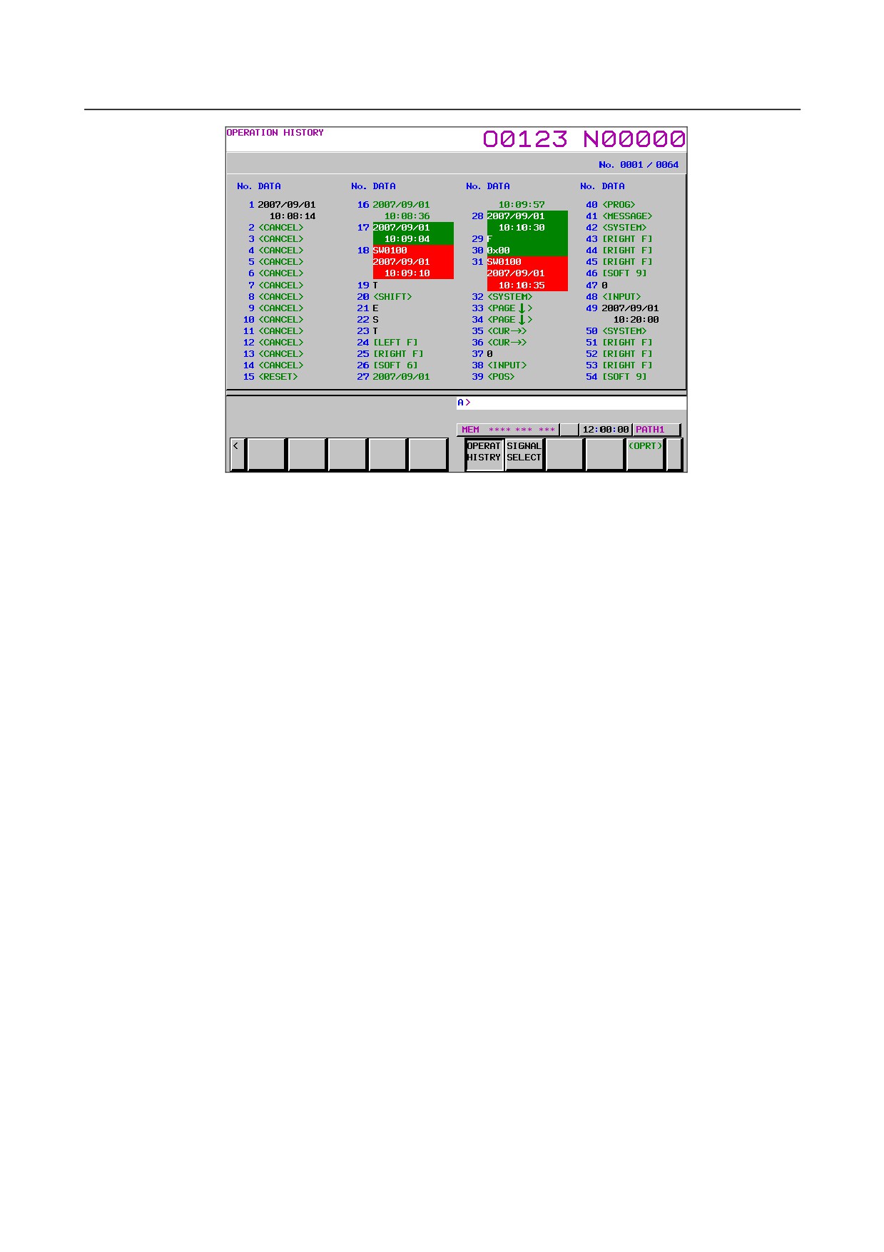
Fig. 1.10.6.3 (a) Operation history screen
Displayed information
1
Serial number and display start history number/total number of history items
A serial number is indicated to the left of each of recorded history data items. The smaller the serial
number, the older the data item.
The display start history number/total number of history items is displayed at the upper right of the
screen. The number of history data items that is not displayed on the screen is not included in the
total number of history items.
2
Data
•
MDI key
When bit 5 (HKE) of parameter No. 3195 is 0, key operations are recorded.
A key operation is preceded by a path number as follows: 1_[LEFT F] or 2_[LEFT F]. (When
the number of paths is 1, no path number is displayed.)
P_ of P_[LEFT F] indicates an external key operation.
i
Address keys, numerical keys
Characters such as A to Z, 0 to 9, ";", "+", and "-" are directly displayed with black text.
ii
Function menu keys, operation menu keys, soft keys
A key name is enclosed by square brackets as follows and displayed with green text:
[LEFT F], [SOFT 1] to [SOFT 10], [RIGHT F].
iii
Function keys, page keys, cursor keys, etc.
A key name is enclosed by angle brackets as follows and displayed with green text:
<POS>, <SYSTEM>, <PAGE ↑>, <CUR →>, <RESET>, <INPUT>, etc.
iv Key at power-on
A key name is displayed with white text against a green background.
- 145 -
1.DISPLAY AND OPERATION
B-64485EN/01
•
Input/output signals
When bit 6 (HDE) of parameter No. 3195 is 0, the input/output signal specified on the
operation history signal selection screen is recorded. The address of the signal and a change in
each bit are displayed. This display is performed with purple text.
G000.2 ↓
An up arrow indicates a change from 0 to 1.
A down arrow indicates a change from 1 to 0.
Indicates a bit.
Indicates the address of a signal.
NOTE
1 When multiple bits at the same address change at the same timing, the
change is handled as one history data item.
2 A change in a signal less than 4 msec is not recorded as history data.
•
Alarm
The number of an alarm and the time when the alarm occurred are displayed on the operation
history screen.
The display is performed with white text against a red background.
Indicates a path number.
Indicates an alarm number.
Indicates a servo axis name for a servo axis.
Indicates a spindle name or number for a spindle.
1_OT0506( XA1)
2004/01/11 Indicates the year/month/date and time on two lines.
11:22:33
If a path name, axis name, or spindle name is changed after occurrence of an alarm, the new
name is displayed.
•
Date/time
The data and time of the following items are displayed on two lines.
i
The date and time of power-on are displayed with white text against a green background.
ii
The date and time of power-off are displayed with green text.
iii
The date when the date changes is displayed with black text.
iv
The dates and times at certain time intervals set in parameter No. 3122 are displayed with
black text.
v The date and time when history data was deleted is displayed with black text.
NOTE
1 In storing time data at certain time intervals, if data to be stored is not present
within a certain time period, the time data is not stored. (If time data is stored
because the date changes, data to be stored is assumed to be present.)
2 If the date and time of a CNC system is changed, the new date and time may be
recorded as the date and time in iii or iv.
History data not displayed on the screen
In addition to history data such as the MDI key, input/output signal state, alarm that occurred, external
operator message (not displayed on the operation history screen), and time stamp, the following data can
be displayed together with time data. These history data items cannot be displayed on the screen, but can
be output to external input/output units (see the section about outputting of all history data).
- 146 -

B-64485EN/01
1.DISPLAY AND OPERATION
1
Detailed data during occurrence of an alarm
When bit 7 (HAL) of parameter No. 3196 is 0, 10 G code modals of the block that was being
executed during occurrence of an alarm, the second auxiliary function codes D, E, F, H, M, N, O, S,
and T, absolute values, and machine coordinates are recorded together with the alarm number and
the time of occurrence.
The group numbers of 10 G code modals to be recorded are set in parameters Nos. 12990 to 12999.
If they are not set, the G code modals of groups 01 to 10 are recorded.
NOTE
For modal 'O' data, only the first five characters are recorded in the case of the
program name.
To increase the number as compared with detailed data on occurrence of an
alarm, set bit 7 (HAL) of parameter No. 3196 to 1.
2
External alarm message and macro alarm message
When bit 3 (EAH) of parameter No. 3112 is 1, external alarm messages and macro alarm messages
can be recorded as history data. However, only the first 64 characters are recorded.
NOTE
To record external alarm messages and macro alarm messages as history data,
set bit 3 (EAH) of parameter No. 3112 to 1 and bit 7 (HAL) of parameter No.
3196 to 0.
3
Changing the tool offset data
When bit 0 (HTO) of parameter No. 3196 is 1, changing the tool offset data records the changed
offset number and type, the changed tool offset data, the new tool offset data, and the change time.
4
Changing the workpiece offset, extended workpiece offset, or workpiece shift (T series) data
When bit 1 (HWO) of parameter No. 3196 is 1, changing the workpiece offset data records the
changed offset number, the changed workpiece offset data, the new workpiece offset data, and the
change time. These items are also recorded when the extended workpiece offset or workpiece shift
amount (for the T series) is changed.
5
Changing a parameter
When bit 2 (HPM) of parameter No. 3196 is 1, changing a parameter records the changed parameter
number, type (axis type, spindle type, path type, and machine group type), the changed parameter
data, the new parameter data, and the change time.
NOTE
History concerning changes during power-on and changes of the password and
keys is not recorded.
6
Changing custom macro common variables (#100 to #999)
When bit 3 (HMV) of parameter No. 3196 is 1, changing a custom macro common variable records
the changed common variable number, the changed common variable value, the new common
variable value, and the change time.
Deleting history data on the operation history screen
-
Procedure
1
Display the operation history screen.
2
Press the soft key [(OPRT)].
- 147 -
1.DISPLAY AND OPERATION
B-64485EN/01
3
Press the soft key [ALL CLEAR].
4
If soft key [EXEC] is pressed, all history data is deleted.
NOTE
The delete operation deletes not only operation history, but also external
operator message history, alarm history, and other history data. Delete operation
cannot be performed on a per-history-type basis.
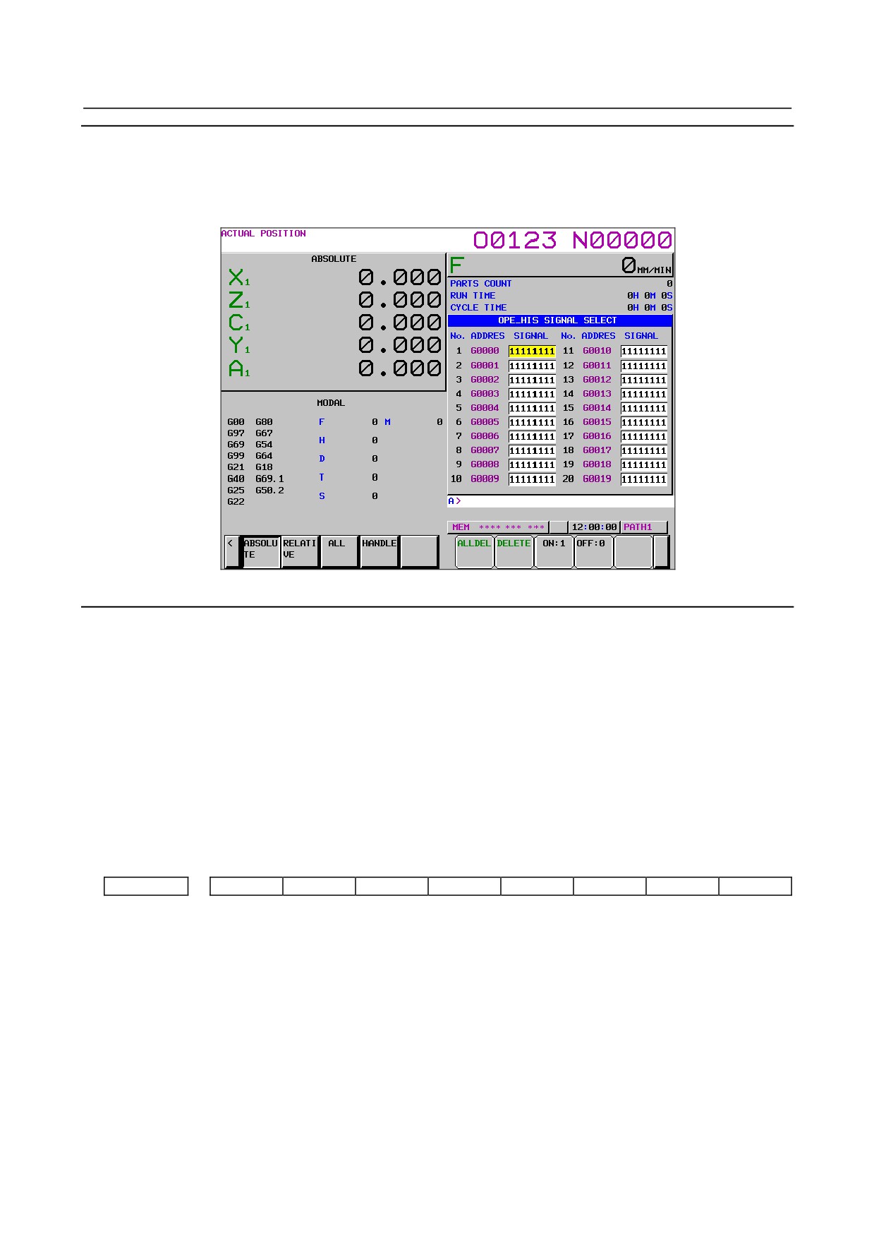
1.10.6.4 Operation history signal selection
An input/output signal for recording history can be selected. A maximum of 60 signals can be set.
Setting data
1
Press function key
2
Press the continuous menu key
several times until soft key [OPERAT HISTRY] is displayed.
3
Press soft key [OPERAT HISTRY].
4
Press soft key [SIGNAL SELECT] to display the operation history signal selection screen.
5
Press soft key [(OPRT)].
6
Press cursor movement keys
to move the cursor to a desired position.
7
Operate keys to enter the signal type (X, G, F, or Y) followed by the address and press
Example) Entering G0004 and pressing
:
Then entered signal address "G0004" appears in the ADDRES position and the initial value
"00000000" is set in the SIGNAL position.
8
Select the bit to be recorded as history.
To change all bits of a specified signal address, move the cursor so that all bits are displayed in
reverse video as "00000000" and then press soft key [ON:1] or [OFF:0] to change the bits to
"11111111" or "00000000".
To change only a particular bit, move the cursor with cursor movement keys
to the bit to
be changed and then press soft key [ON:1] or [OFF:0] to change the bits to 1 or 0.
9
A maximum of 60 signals can be selected. It is not necessary to set signals contiguously from No. 1.
NOTE
1 When the operation history signal selection screen is displayed, no history is
recorded.
2 The addresses that can be set for an input/output signal are X, Y, G, and F only.
When no data is set, ******** appears.
3 If all bits are 0 even when an address is set, no history is recorded.
4 When the ON/OFF width of an input signal is 4 msec or less, nothing is recorded
in history data. Some signals are not recorded.
5 When the number of selected signals is large, the processing speed may be
reduced.
Clearing individual data items
1
Display the operation history signal selection screen.
2
Move the cursor to the data to be cleared.
3
Press soft key [DELETE].
4
Press soft key [EXEC].
- 148 -
B-64485EN/01
1.DISPLAY AND OPERATION
Clearing all data items
1
Display the operation history signal selection screen.
2
Press soft key [ALLDEL].
3
Press soft key [EXEC].
Fig. 1.10.6.4 (a) Operation history signal selection screen
Selection by the parameter
When bit 4 (PHS) of parameter No. 3206 is 1, an input/output signal for which history is recorded can be
set by the parameter.
When a signal is selected or deselected on the operation history signal selection screen in this case, the
value of the corresponding parameter automatically changes. When the value of the parameter is changed
on the parameter screen, the display of the operation history signal selection screen changes.
This is the same as in input operations. When operation history signal selection data is input on the
operation history signal selection screen, the value of the corresponding parameter automatically changes.
When the value of parameter is input on the parameter screen, the display of the operation history signal
selection screen changes.
The first 20 data items of the 60 data items can be set by the parameter.
Parameter setting
#7
#6
#5
#4
#3
#2
#1
#0
3206
PHS
[Input type] Parameter input
[Data type] Bit
#4 PHS Operation history signal selection:
0: Does not interact with parameters.
Operation history signal selection is added or deleted on the operation history signal
selection screen.
Changing the settings of parameters Nos. 24901 to 24920, Nos. 12801 to 12820,
Nos. 12841 to 12860, or Nos. 12881 to 12900 has no effect on operation history
signal selection.
Changes to the signals of the addresses specified by parameters Nos. 24901 to 24920,
Nos. 12801 to 12820, Nos. 12841 to 12860, or Nos. 12881 to 12900 are not
recorded in the history.
- 149 -
1.DISPLAY AND OPERATION
B-64485EN/01
1: Interacts with parameters.
Operation history signal selection can be performed either on the operation history
signal selection screen or by setting parameters.
NOTE
Setting this parameter to 1 reflects the current operation history
signal selection data on parameters Nos. 24901 to 24920 and Nos.
12801 to 12900.
24901
Operation history signal selection PMC path number (No. 01)
to
to
24920
Operation history signal selection PMC path number (No. 20)
[Input type] Parameter input
[Data type] Byte
[Valid data range] 0 to 3
These parameters set operation history signal selection PMC path numbers Nos. 1 to 20.
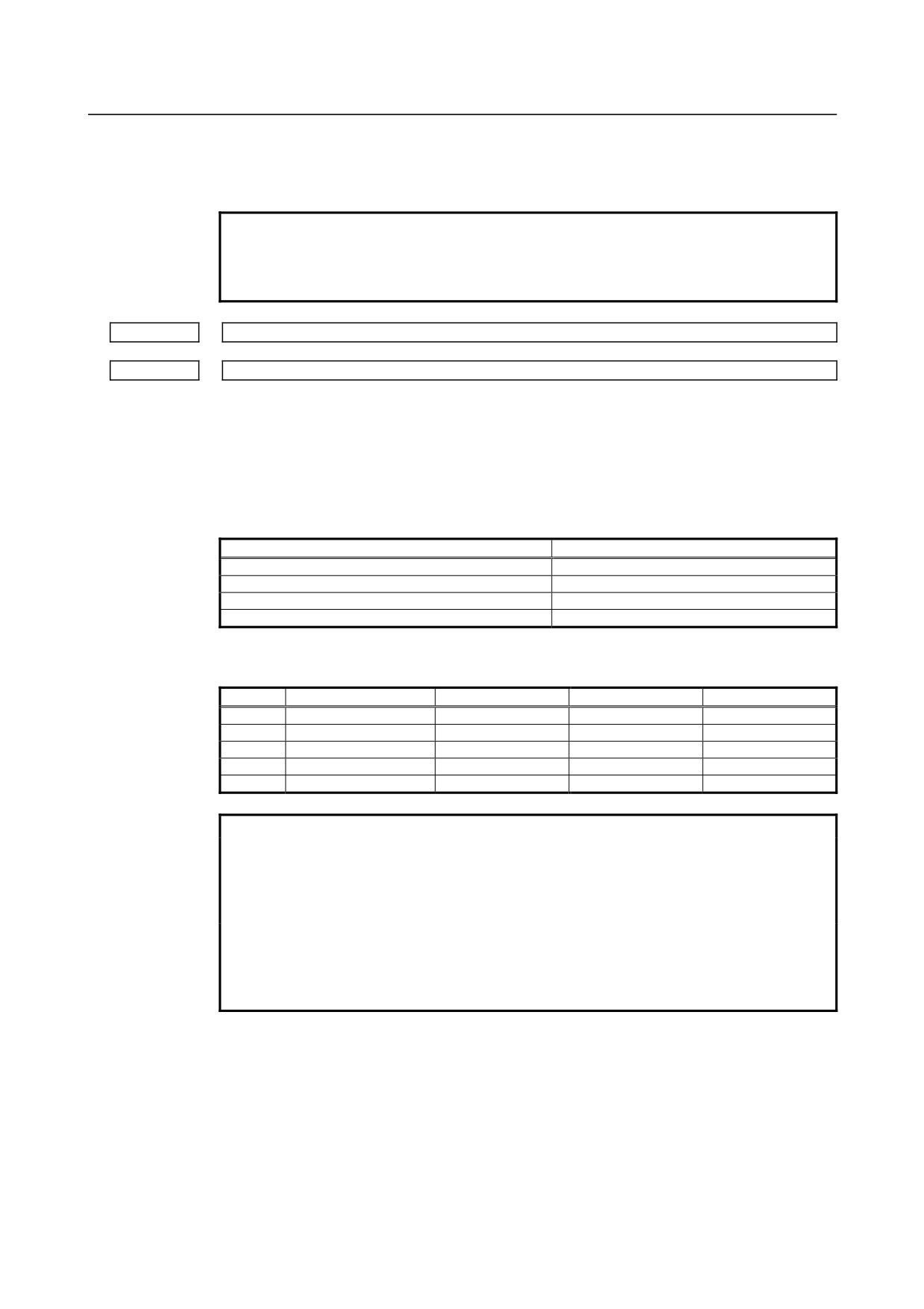
The correspondence between PMC path numbers and settings is as given in the Table
1.10.6.4 (a).
Table 1.10.6.4 (a)
PMC path number
Parameter value
Not selected.
0
1st PMC
1
2nd PMC
2
3rd PMC
3
These parameters are paired with other parameters as given below (Table 1.10.6.4 (b)).
Table 1.10.6.4 (b)
No.
PMC path number
Address type
Address number
Bit number
01
No. 24901
No. 12801
No. 12841
No. 12881
02
No. 24902
No. 12802
No. 12842
No. 12882
03
No. 24903
No. 12803
No. 12843
No. 12883
…
…
…
…
20
No. 24920
No. 12820
No. 12860
No. 12900
NOTE
1 Operation history signals that can be selected and deselected with
parameters are for the first 20 of 60 sets. If an operation history
signal is specified from the operation history signal selection
screen, the PMC path number is fixed at the first PMC.
2 To deselect a signal, set 0.
At this time, 0 is set as the initial value in the address type (Nos.
12801 to 12820), the address number (Nos. 12841 to 12860), and
the bit number (Nos. 12881 to 12900) corresponding to that signal.
- 150 -
B-64485EN/01
1.DISPLAY AND OPERATION
NOTE
3 When a PMC path number is set, 1 is set as the initial value in the
address type (Nos. 12801 to 12820) corresponding to that signal,
and 0 is set as the initial value in the address number (Nos. 12841
to 12860) and the bit number (Nos. 12881 to 12900).
[Example]
If parameter No. 24901 is set to 1, the parameters are initialized
as follows:
No. 12801=1
Address type
No. 12841=0
Address number
No. 12881=00000000
Bit number
If, however, the address type (Nos. 12801 to 12820) corresponding
to that signal is set, the address type (Nos. 12801 to 12820), the
address number (Nos. 12841 to 12860), and the bit number (Nos.
12881 to 12900) will not be initialized.
4 If an attempt is made to set a value that cannot be set, a warning,
"DATA IS OUT OF RANGE" appears; retry setting a value.
12801
Operation history signal selection address type (No. 01)
to
to
12820
Operation history signal selection address type (No. 20)
[Input type] Parameter input
[Data type] Byte
[Valid data range] 0 to 4
These parameters set operation history signal selection address types Nos. 1 to 20.
The correspondence between address types and settings is as given in the Table 1.10.6.4
(c).
Table 1.10.6.4 (c)
Address type
Parameter value
Not selected.
0
X
1
G
2
Y
3
F
4
These parameters are paired with other parameters as given below (Table 1.10.6.4 (d)).
Table 1.10.6.4 (d)
No.
PMC path number
Address type
Address number
Bit number
01
No. 24901
No. 12801
No. 12841
No. 12881
02
No. 24902
No. 12802
No. 12842
No. 12882
03
No. 24903
No. 12803
No. 12843
No. 12883
…
…
…
…
20
No. 24920
No. 12820
No. 12860
No. 12900
NOTE
1 Operation history signals that can be selected and deselected with
parameters are for the first 20 of 60 sets. If an operation history
signal is specified from the operation history signal selection
screen, the PMC path number is fixed at the first PMC.
- 151 -
1.DISPLAY AND OPERATION
B-64485EN/01
NOTE
2 To deselect a signal, set 0.
At this time, 0 is set as the initial value in the address number (Nos.
12841 to 12860) and the bit number (Nos. 12881 to 12900)
corresponding to that signal.
3 When an address type is set, 1 is set as the initial value in the PMC
path number (Nos. 24901 to 24920) corresponding to that signal,
and 0 is set as the initial value in the address number (Nos. 12841
to 12860) and the bit number (Nos. 12881 to 12900).
[Example]
If parameter No. 12801 is set to 2, the parameters are initialized
as follows:
No. 24901=1
PMC path number
No. 12841=0
Address number
No. 12881=00000000
Bit number
If, however, the PMC path number (Nos. 24901 to 24920)
corresponding to that signal is set, the PMC path number (Nos.
24901 to 24920) will not be initialized.
4 If an attempt is made to set a value that cannot be set, a warning,
"DATA IS OUT OF RANGE" appears; retry setting a value.
12841
Operation history signal selection address number (No. 01)
to
to
12860
Operation history signal selection address number (No. 20)
[Input type] Parameter input
[Data type] Word
[Valid data range] For an explanation of the address ranges of the G, F, X, and Y signals, refer to the PMC
Programming Manual (B-64513EN).
These parameters set operation history signal selection address numbers Nos. 1 to 20.
These parameters are paired with other parameters as given below (Table 1.10.6.4 (e)).
Table 1.10.6.4 (e)
No.
PMC path number
Address type
Address number
Bit number
01
No. 24901
No. 12801
No. 12841
No. 12881
02
No. 24902
No. 12802
No. 12842
No. 12882
03
No. 24903
No. 12803
No. 12843
No. 12883
…
…
…
…
20
No. 24920
No. 12820
No. 12860
No. 12900
NOTE
1 Operation history signals that can be selected and deselected with
parameters are for the first 20 of 60 sets.
2 When an address number is set, 0 is set as the initial value in the
bit number (Nos. 12881 to 12900) corresponding to that signal.
3 If an attempt is made to set a value that cannot be set or if the
address type (Nos. 12801 to 12820) corresponding to that signal is
0, a warning, "DATA IS OUT OF RANGE" appears; retry setting a
value.
- 152 -
B-64485EN/01
1.DISPLAY AND OPERATION
#7
#6
#5
#4
#3
#2
#1
#0
12881
RB7
RB6
RB5
RB4
RB3
RB2
RB1
RB0
to
to
12900
RB7
RB6
RB5
RB4
RB3
RB2
RB1
RB0
[Input type] Parameter input
[Data type] Bit
RB7 - RB0 History of the respective operation history signal selection bits Nos. 1 to 20 (RB7 to RB0)
corresponding to the operation history signal selection addresses set in parameters Nos.
12801 to 12860 is:
0 : Not retained. (History of the bit is not recorded.)
1 : Retained. (History of the bit is recorded.)
These parameters are paired with other parameters as given below (Table 1.10.6.4 (f)).
Table 1.10.6.4 (f)
No.
PMC path number
Address type
Address number
Bit number
01
No. 24901
No. 12801
No. 12841
No. 12881
02
No. 24902
No. 12802
No. 12842
No. 12882
03
No. 24903
No. 12803
No. 12843
No. 12883
…
…
…
…
20
No. 24920
No. 12820
No. 12860
No. 12900
1.10.6.5 Outputting all history data
All history data items can be output to an external input/output unit.
History data items cannot be output individually.
Procedure
1
Make sure the output device is ready for output.
2
Enter the EDIT mode.
3
Press function key
4
Press the continuous menu key
several times until soft key [OPERAT HISTRY] is displayed.
5
Press soft key [OPERAT HISTRY] and then press soft key [OPERAT HISTRY] that newly appears
to display the operation history screen.
6
Press soft key [(OPRT)].
7
Press soft key [PUNCH].
8
Enter the file name and press soft key [EXEC].
When pressing soft key [EXEC] without entering a file name, the name of the output file name is
"OPRT_HIS.TXT".
Output format
History is output as an ASCII file in the following format.
1
MDI key
"MDI" is followed by "path number_", "key data", and "input time".
(The key data that is input during power-on is indicated as "Power on MDI".)
<Example>
MDI 01_A 12:23:34
MDI 02_<CAN> 12:23:34
MDI 02_[SOFT HF1] 12:23:35
MDI P_<RESET> 12:34:56
Power on MDI 01_<RESET> 12:34:56
- 153 -
1.DISPLAY AND OPERATION
B-64485EN/01
2
Input/output signal
"DI/DO" is followed by "PMC number_", "signal address bit state", and "change time".
<Example>
DI/DO 1_F0002.2_on 12:34:56
DI/DO 1_ G0043.0_off G0043.1_off 12:35:00
(Example of the same address and multiple bits)
3
Alarm
"Alarm" is followed by "path number_", "type", "alarm number", "G code modal data", "non-G-code
modal data", each axis "absolute coordinates", "machine coordinates", and "data and time of
occurrence".
The modal data for which a command is present in the block that was being executed during
occurrence of an alarm is preceded by "*".
<Example>
•
Alarm 01_SR01973
*G0. G97. G69. G99. G21. G50.2 G25. G13.1 B0. D0. E0. *F100. H0. M10. *N123. Test_
S1000. T1010.
X1 ABS 197.999 MCN 197.999 Y1 ABS -199806.00 MCN -199806.00 Z1 ABS 297.009
MCN 0.123 C1 ABS 10395.999 MCN 0.000 at 2007/09/01 19:03:28
•
Alarm 02_ OT00506(ZA2)
*G1. G17. G90. G22. G94. G20. *G42. G49. G80. G12.1 B0. *D12. E0. *F100. H34. M0.
*N123. O123 S0. T0.
X2 ABS 123.999 MCN 234.000 Y2 ABS -123.00 MCN -234.00 ZA2 ABS 1234.567 MCN
-1234.567 at 2007/09/01 12:34:56
•
When no additional information is recorded during occurrence of an alarm (bit 7 (HAL) of
parameter No. 3196 is 1), only "path number_", "alarm number", and "data and time of
occurrence" are output.
Alarm 01_OT00506(XC1) at 2007/09/01 22:08:32
Alarm 02_SW00100 at 2007/09/01 19:07:52
•
When external alarm messages and macro alarm messages are recorded (bit 7 (HAL) of
parameter No. 3196 is 0 and bit 3 (EAH) of parameter No. 3112 is 1), the messages are also
output.
Alarm 01_MC00001 Message ATC ALARM
G0. G97. G69. G99. G21. G40. G25. G22. G80. D0. E0. F0. H0. M0. N0. O9999 S0. T0.
X2 ABS 10.000 MCN 0.000Y2 ABS 123.000 MCN 0.000Z2 ABS 0.000 MCN 0.000 at
2007/09/01 10:06:43
4
External operator message
"EXT_Message" is followed by "message number", "message", and "data and time of occurrence".
<Example>
EXT_Message 01234 OIL PRESSURE DECREASE at 2007/09/01 2:38:43
5
Changing the tool offset data
"Tool Offset" is followed by "path number", "type", "offset number", "changed offset data",
"changing offset data", and "change time". The type is described below.
Common to M/T
:
G = geometric compensation
W = wear compensation
M series
:
H = tool length compensation
D = cutter compensation
T series
:
R = tool-nose radius compensation
T = tool direction
X2, Z2, Y2 = second geometric compensation
<Example>
Tool Offset 01_X0002 0.000 → 1 at 12:15:43
Tool Offset 02_XW0001 -9999.999 → 9999.999 at 12:15:46
Tool Offset 01_RG0032 0.000 → 0.003 at 12:15:52
Tool Offset 02_T0001 5. → 2. at 19:34:11
- 154 -
B-64485EN/01
1.DISPLAY AND OPERATION
Tool Offset 02_W0123 -10.000 → 123.456 at 10:28:58
Tool Offset 01_HG0456 0.000 → 999.999 at 11:37:40
Tool Offset 01_
0064 12.340 → 12.569 at 11:39:42
6
Changing the workpiece offset/extended workpiece offset/workpiece shift (T series) data
"Work Offset/EXT Work Offset/Work Shift" is followed by "path number_(axis name)", "type",
"offset number", "changed offset data", "changing offset data", and "change time".
<Example>
Work Offset 01_G55(XA1) 15.000 → 0.007 at 09:23:03
Work Offset 02_EXT(Z2) 0.000 → 300.003 at 09:22:50
EXT Work Offset 02_G54.1P300 (Y2) 123.456 → 9999.999 at 12:15:46
Work Shift (X) 02_999999.999 → 999999.999 at 10:22:37
7
Changing a parameter
"Parameter" is followed by "type", "parameter number", "changed parameter", "changing parameter",
and "change time".
The type is described below.
Path type:
A path number is preceded by L.
Axis type:
An axis number is preceded by A.
Spindle type: A spindle number of preceded by S.
Machine group type: A machine group is preceded by T.
Others:
No type is output.
<Example>
Parameter N03112
00000100 → 00001100 at
11:18:40
Parameter Path type N01410 L02
0.000 → 1000.000 at
18:58:48
Parameter Axis type N01423 A04(B2)
0.000 → 10000.000 at
18:58:48
Parameter Spindle type N04011 S1(S)
10011010 → 10011010 at
18:58:53
Parameter Machine type N06310 T01
0 → -32768 at
19:21:13
8
Changing custom macro common variables (#100 to #999)
"Macro variable" is followed by "path number", "#variable name", "changed common variable",
"changing common variable", and "change time".
Variables are output in the data form of M × (10**(-E)).
<Example>
•
When #149 of the first path is changed from empty to 12.345
Macro variable 01_#149 Empty → 123450000*(10**-7) at 15:02:35
•
When #549 of the second path is changed from -12.345 to 123456789012
Macro variable 02_#549 -123450000*(10**-7) →123456789*(10**3) at 15:03:27
9
Data/time
Power on at 2007/09/01 17:11:17
(Data/time of power-on)
Power off at 2007/09/01 17:49:17
(Data/time of power-off)
Date 2007/09/01 00:00:00
(Record of date change)
Time stamp at 2007/09/01 15:51:00
(Record at certain time intervals)
Data delete at 2007/09/01 10:56:18
(Data/time of history data deletion)
- 155 -
1.DISPLAY AND OPERATION
B-64485EN/01
1.11 SYSTEM ALARM HISTORY SCREEN
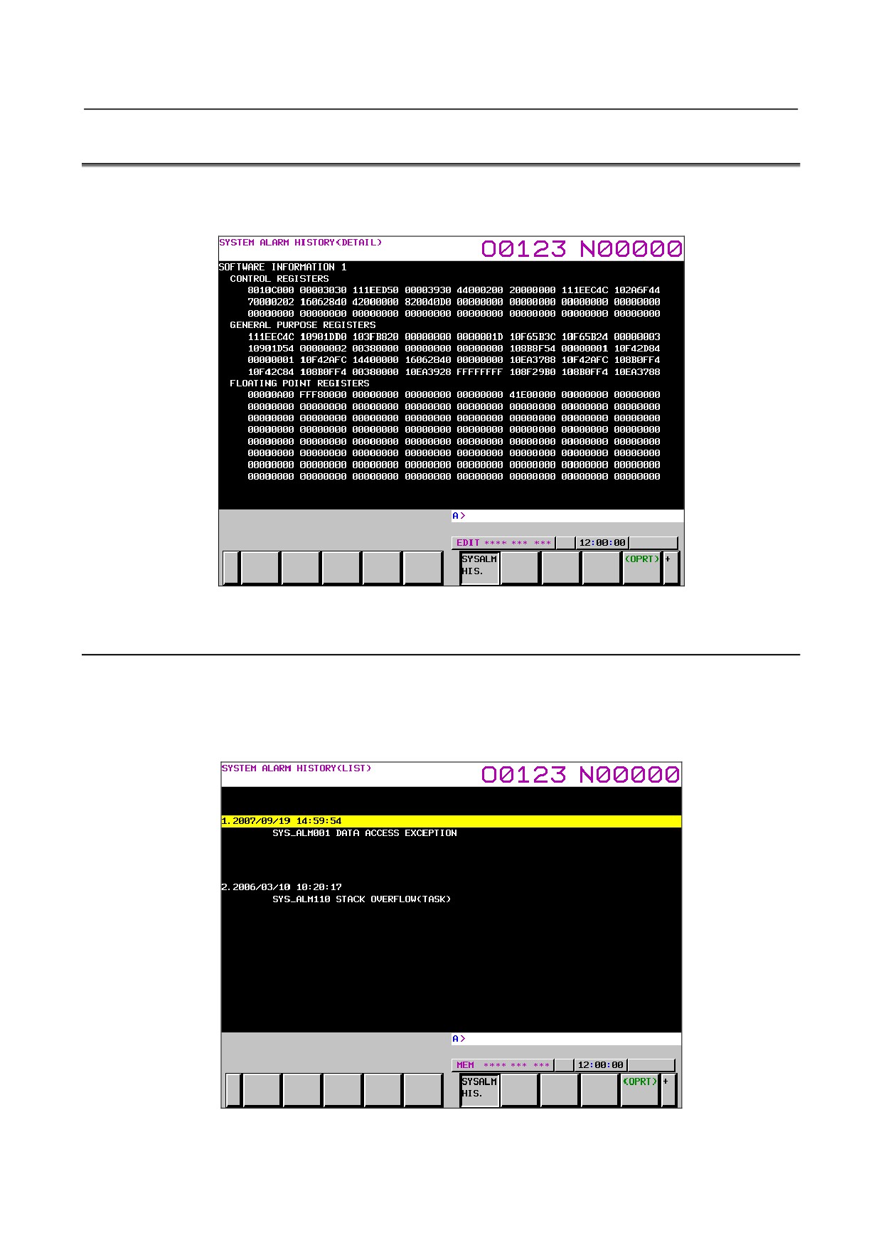
On the system alarm history screen, a maximum of two system alarms that occurred can be displayed. In
addition, system alarm information can be output to an external unit.
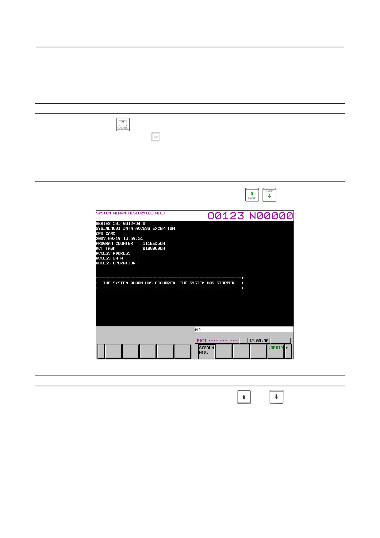
Fig. 1.11 (a) System alarm history screen
1.11.1 System Alarm History List Screen
The system alarm history list screen lists the system alarms history items that are currently recorded, as
shown in Fig. 1.11 (b).
A maximum of two system alarm information items including the latest system alarm information can be
displayed by setting bit 2 (NMH) of parameter No. 3103.
Fig. 1.11 (b) System alarm history list screen
- 156 -
B-64485EN/01
1.DISPLAY AND OPERATION
The following information is displayed.
(1) Date and time of system alarm issuance
(2) System alarm number
(3) System alarm message
Procedure
1
Press function key
2
Press the continuous menu key
several times until soft key [SYSALM HIS.] is displayed.
3
Press soft key [SYSALM HIS.].
4
The system alarm history list screen as shown in Fig. 1.11 (b) appears.
1.11.2 System Alarm History Detail Screen
This screen displays details on system alarms. Page switching keys
,
can be used to switch
between pages to be displayed.
Fig. 1.11 (c) System alarm history detail screen
Procedure
1 On the system alarm history list screen, move the cursor with
and
to the system alarm
history for which detailed information is to be displayed.
2 Press [INPUT] key or soft key [(OPRT)] and then press soft key [SELECT].
3 Details of the selected system alarm history are displayed.
To move from the system alarm history detail screen to the list screen, follow the steps below.
1
On the system alarm history detail screen, press soft key [(OPRT)] and then press [RETURN].
2
The system alarm history list screen appears.
- 157 -
1.DISPLAY AND OPERATION
B-64485EN/01
1.11.3 Outputting System Alarm History
This section describes the procedure for outputting system alarm history to an external unit.
Procedure
1
On the system alarm history detail screen, press soft key [(OPRT)] and press soft key [F OUTPUT].
2
Enter the name of a file to which history is output. If no file name is specified, the default file name
(SYS-ALM.TXT) is assumed.
3
Press soft key [EXEC].
1.11.4 Parameter
#7
#6
#5
#4
#3
#2
#1
#0
3103
NMH
[Input type] Parameter input
[Data type] Bit
#2 NMH System alarm history screen is:
0: Not displayed.
1: Displayed.
- 158 -
B-64485EN/01
2.CONTROL UNIT HARDWARE
2 CONTROL UNIT HARDWARE
This chapter describes the hardware configuration of the control unit, various printed-circuit boards in the
control unit, their locations, LED indicators, and their locations.
2.1
EXAMPLE OF HARDWARE CONFIGURATION
2.1.1
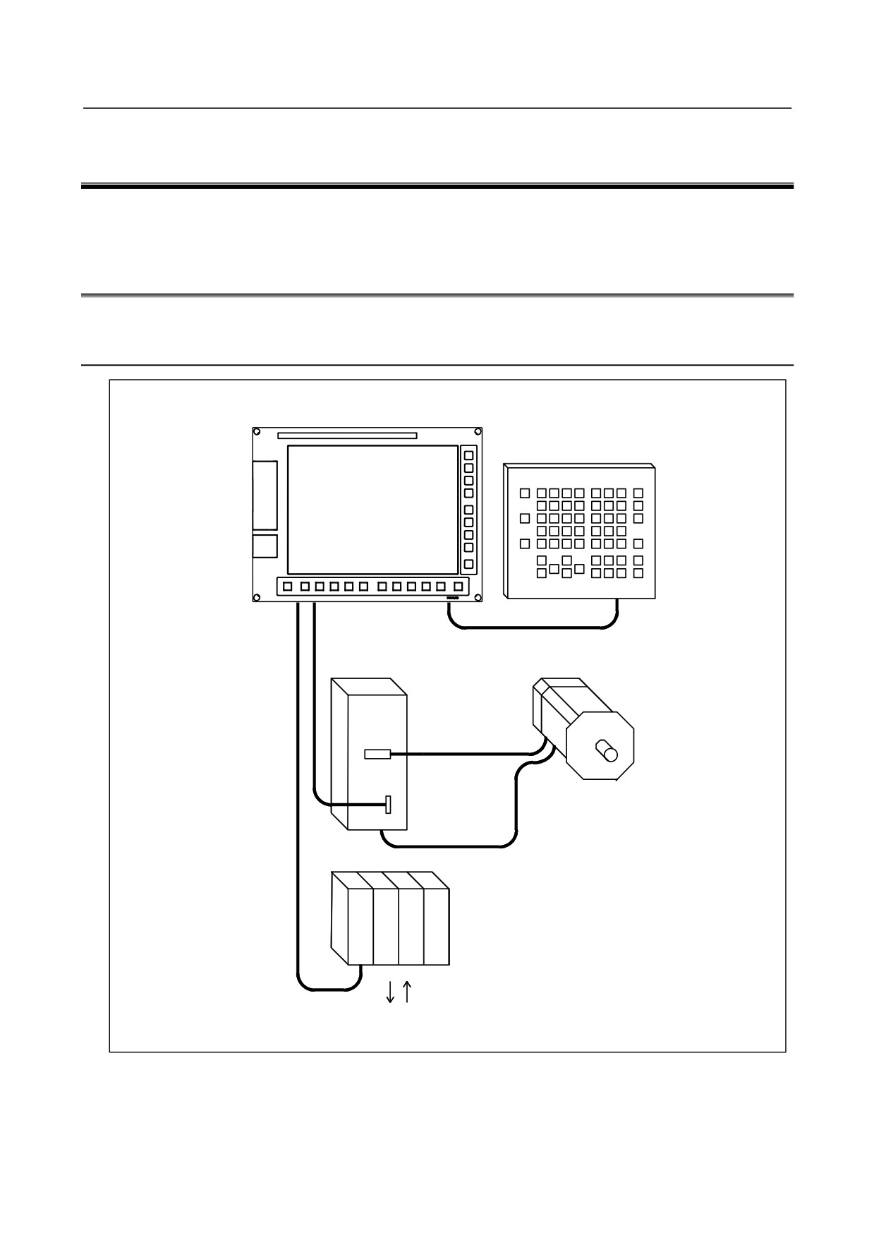
Example of the Hardware Configuration of the LCD-mounted
Type Control Unit
Control unit
MDI unit
Optical fiber cable
Servo motor
Servo amplifier
I/O Link i
or
I/O Link
I/O Unit
Machine operator’s panel/ Power magnetics circuit etc.
- 159 -
2.CONTROL UNIT HARDWARE
B-64485EN/01
2.1.2
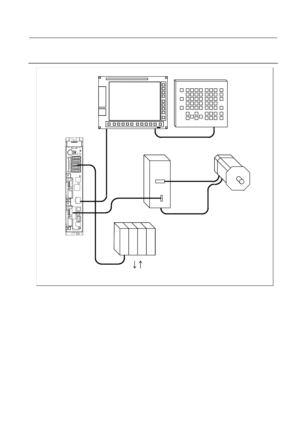
Example of the Hardware Configuration of the Stand-alone
Type Control Unit
Display unit
MDI unit
Control unit
Servo motor
Servo amplifier
Optical fiber cable
I/O Unit
I/O Link i
or
I/O Link
Machine operator’s panel/ Power magnetics circuit etc.
- 160 -
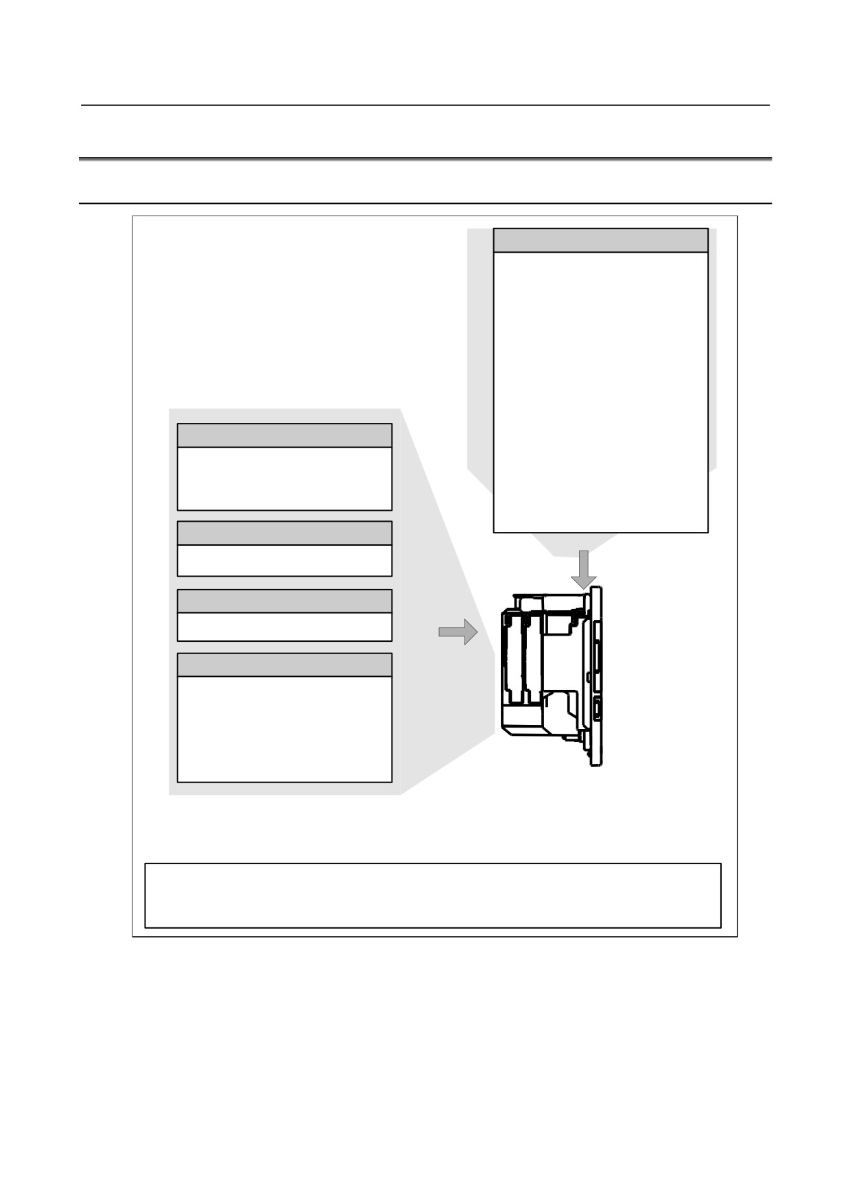
B-64485EN/01
2.CONTROL UNIT HARDWARE
2.2
HARDWARE OVERVIEW
2.2.1
LCD-mounted Type Control Unit Overview
Main board
- CPU for controlling CNC
- Power supply
- Axis control function
- MDI I/F
- I/O Link i, I/O Link control
function
- PMC control function
- High-speed skip (HDI)
- RS-232C I/F
- Memory card I/F
- USB I/F
Fast Ethernet board
- Ethernet function
Fast Ethernet function
- DeviceNet function note2
Data server function
- PC functions (Personal
FL-net function
computer function with
Windows® CE)
Additional axis board
Basic system
Additional axis control function
HSSB interface board
High-speed serial bus interface
Various types of network boards
Options
PROFIBUS-DP master board
PROFIBUS-DP slave board
DeviceNet master board note2
DeviceNet slave board
CC-Link remote device station board
Unit without optional slots
or
Unit having one optional slot
or
Unit having two optional slots
Note
1 On a unit with optional slots, as many optional boards as the slots can be mounted.
2 DeviceNet master functions are provided on the mainboard or on the optional
board,
depending on the specification.
- 161 -