FANUC Series Series 16i-TB, Series 18i-TB, Series 160i-TB, Series 180i-TB. OPERATOR’S MANUAL - page 20
B-63524EN/01
OPERATION
4. AUTOMATIC OPERATION
4.10.5
Connecting PCMCIA
Card Attachment
4.10.5.1
Specification number
Specification
Remarks
A02B-0236-K160
For 7.2″ LCD or 8.4″ LCD
A02B-0236-K161
For 9.5″ LCD or 10.4″ LCD
4.10.5.2
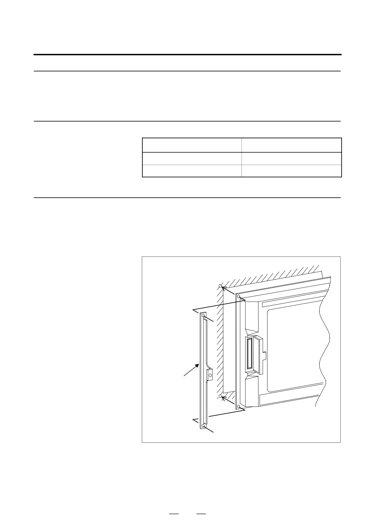
1) How to assemble to the unit
Assemble an attachment guide and a control unit to the cabinet by
Assembling
screwing together as follow figure.
The attachment guide is 1.6mm thick. Pay attention for the length of
the screws when you assemble them.
Attachment
guide
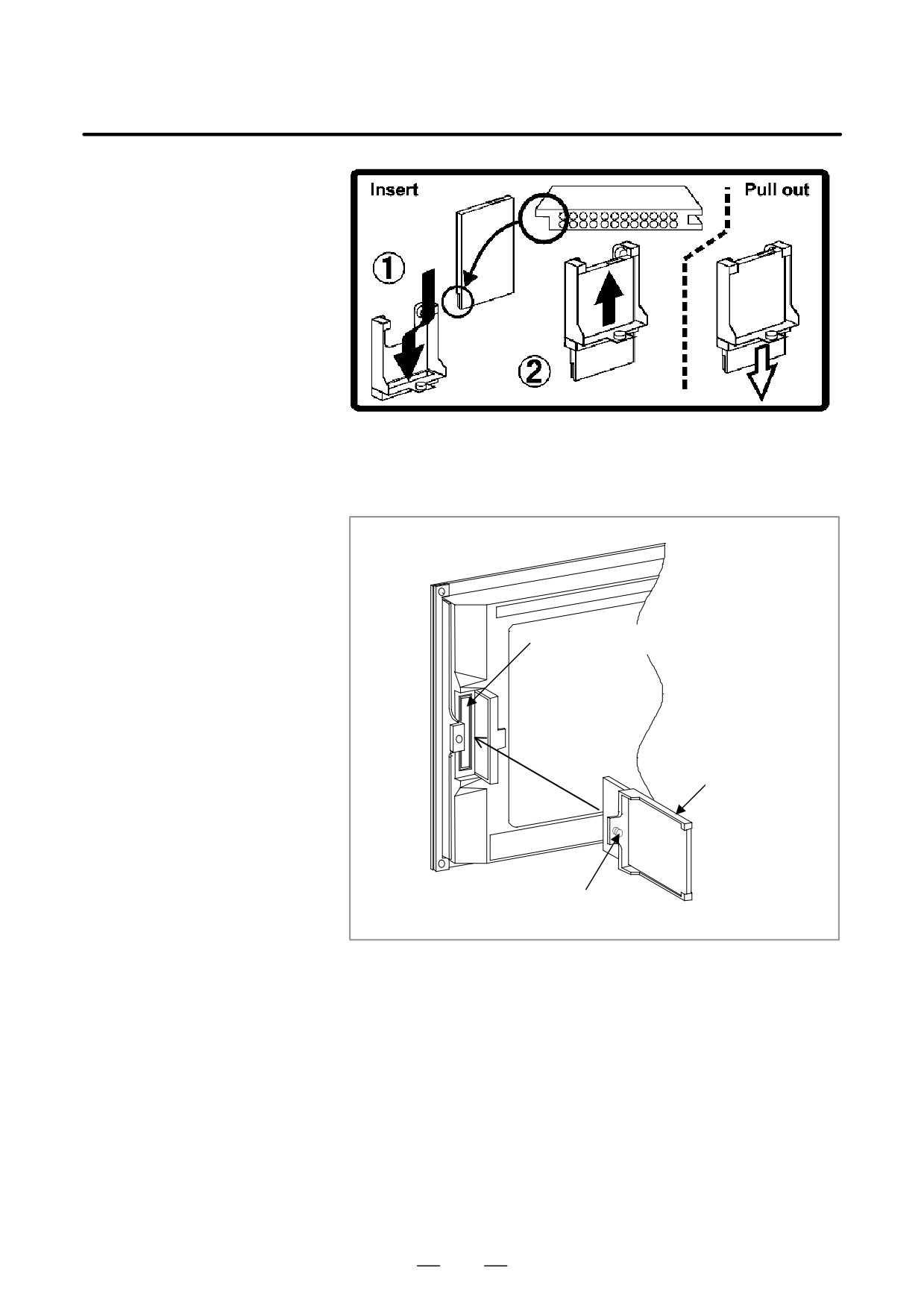
2) How to mount the card
(a) Insert the card to slit of the attachment. Please pay attention to the
direction of the card.
(Please mach the direction of ditch on the
card.)
(b) Push up the card to the upper end of the attachment.
549
4. AUTOMATIC OPERATION
OPERATION
B-63524EN/01
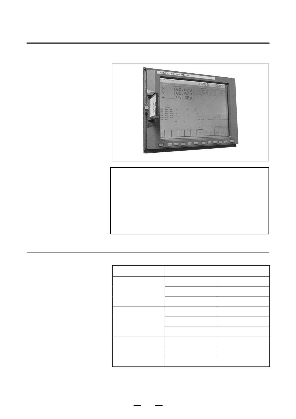
3) Assembling of the attachment
Insert the memory card with the attachment into the memory card
interface as following figure. And, fix the attachment guide by
screwing the screw of the attachment guide by manual.
Memory card inter-
face
attach-
ment
screw to fix the attach-
ment
550
B-63524EN/01
OPERATION
4. AUTOMATIC OPERATION
4) Appearance after connection
NOTE
1
In both case of stand-alone type i series and LCD mounted
type i series, the memory card interface where is the left side
of the screen of the display unit. (The memory card interface
on the stand-alone type controller is not available.)
2
It is impossible to assemble the display unit and the
attachment guide from inside of the cabinet.
3
The memory card must be used in the condition, as the
coolant cannot be poured directly on it.
4.10.6
Recommended
Maker
Type
Capacity
Memory Card
Hitachi LTD
HB289016A4
16MB
HB289032A4
32MB
HB289160A4
160MB
Matushita electric
BN-012AB
12MB
BN-020AB
20MB
BN-040AB
40MB
SanDisk
SDP3B-4
4MB
SDP3B-20
20MB
SDP3B-40
40MB
551
5. TEST OPERATION
OPERATION
B-63524EN/01
TEST OPERATION
5
The following functions are used to check before actual machining
whether the machine operates as specified by the created program.
1. Machine Lock and Auxiliary Function Lock
2. Feedrate Override
3. Rapid Traverse Override
4. Dry Run
5. Single Block
552
B-63524EN/01
OPERATION
5. TEST OPERATION
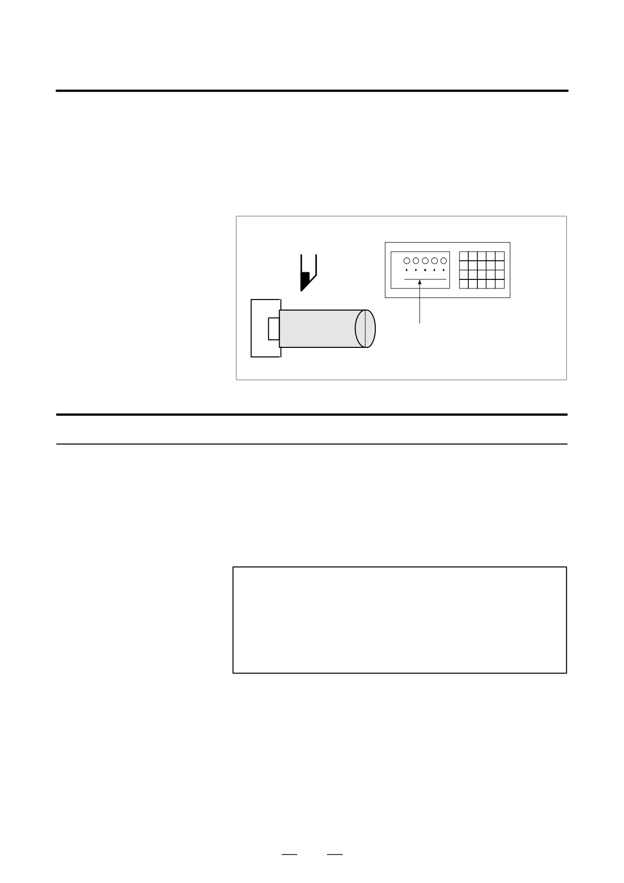
To display the change in the position without moving the tool, use
5.1
machine lock.
MACHINE LOCK AND
There are two types of machine lock, all-axis machine lock, which stops
AUXILIARY
the movement along all axes, and specified-axis machine lock, which
FUNCTION LOCK
stops the movement along specified axes only. In addition, auxiliary
function lock, which disables M, S, and T commands, is available for
checking a program together with machine lock.
MDI
X
Z
Tool
Workpiece
The tool does not move but the position
along each axis changes on the display.
Fig. 5.1 Machine lock
Procedure for Machine Lock and Auxiliary Function Lock
D Machine Lock
Press the machine lock switch on the operator’s panel. The tool does not
move but the position along each axis changes on the display as if the tool
were moving.
Some machines have a machine lock switch for each axis. On such
machines, press the machine lock switches for the axes along which the
tool is to be stopped. Refer to the appropriate manual provided by the
machine tool builder for machine lock.
WARNING
The positional relationship between the workpiece
coordinates and machine coordinates may differ before and
after automatic operation using machine lock. In such a
case, specify the workpiece coordinate system by using a
coordinate setting command or by performing manual
reference position return.
Press the auxiliary function lock switch on the operator’s panel. M, S, T,
D Auxiliary Function Lock
and B codes are disabled and not executed. Refer to the appropriate
manual provided by the machine tool builder for auxiliary function lock.
553
5. TEST OPERATION
OPERATION
B-63524EN/01
Restrictions
D M, S, T, and B command
M, S, T, and B commands are executed in the machine lock state.
by only machine lock
D Reference position
When a G27, G28, or G30 command is issued in the machine lock state,
return under Machine
the command is accepted but the tool does not move to the reference
Lock
position and the reference position return LED does not go on.
D M codes not locked by
M00, M01, M02, M30, M98, M99, and M198 commands (subprogram
auxiliary function lock
call function) are executed even in the auxiliary function lock state.
M codes for calling a subprogram (parameters No. 6071 to 6079) and
those for calling a custom macro (parameter No. 6080 to 6089) are also
executed.
554
B-63524EN/01
OPERATION
5. TEST OPERATION
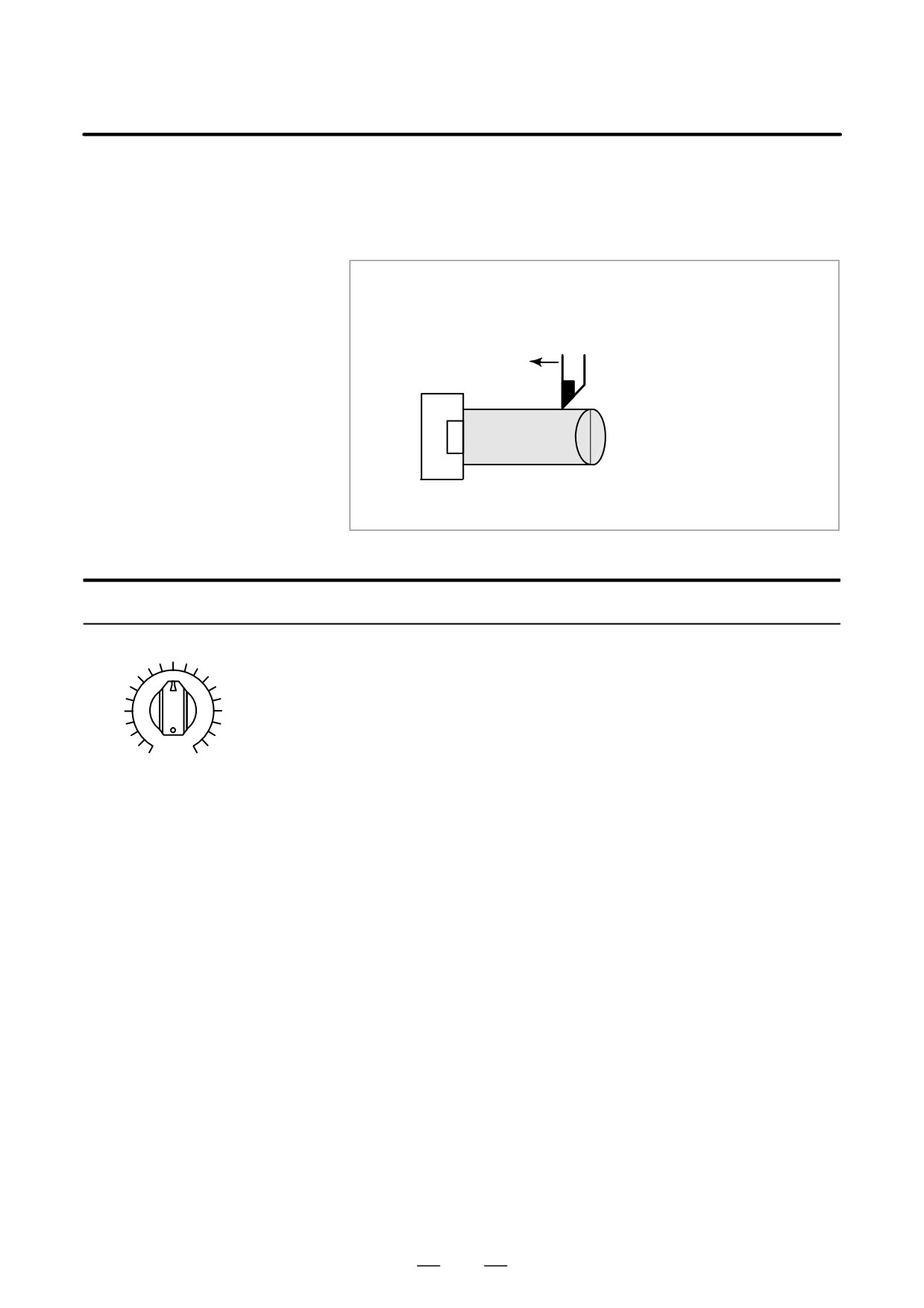
A programmed feedrate can be reduced or increased by a percentage (%)
5.2
selected by the override dial. This feature is used to check a program.
FEEDRATE
For example, when a feedrate of 100 mm/min is specified in the program,
OVERRIDE
setting the override dial to 50% moves the tool at 50 mm/min.
Feedrate 100 mm/min
(Specified by programmed)
Tool
Check the machining
by altering the feedrate
Feedrate 50 mm/min after
from the value speci-
feedrate override
fied in the program.
Workpiece
Fig. 5.2 Feedrate override
Procedure for Feedrate Override
Set the feedrate override dial to the desired percentage (%) on the
machine operator’s panel, before or during automatic operation.
On some machines, the same dial is used for the feedrate override dial
and manual continuous feedrate dial. Refer to the appropriate manual
provided by the machine tool builder for feedrate override.
0
200
JOG FEED RATE OVERRIDE
Restrictions
D Override Range
The override that can be specified ranges from 0 to 254%. For individual
machines, the range depends on the specifications of the machine tool
builder.
D Override during thread
During threading, the override is ignored and the feedrate remains as
specified by program.
555
5. TEST OPERATION
OPERATION
B-63524EN/01
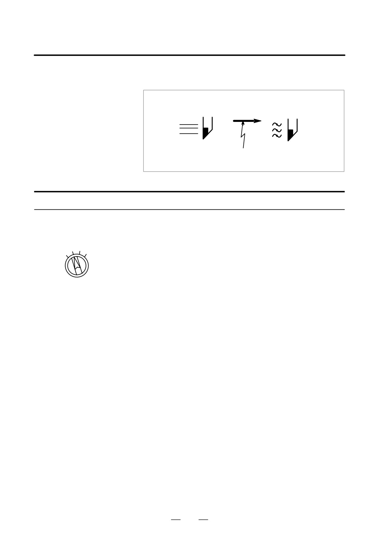
An override of four steps (F0, 25%, 50%, and 100%) can be applied to the
5.3
rapid traverse rate. F0 is set by a parameter (No. 1421).
RAPID TRAVERSE
OVERRIDE
Rapid traverse
5m/min
rate10m/min
Override
50%
Fig. 5.3 Rapid traverse override
Procedure for Rapid Traverse Override
Select one of the four feedrates with the rapid traverse override switch
during rapid traverse. Refer to the appropriate manual provided by
the machine tool builder for rapid traverse override.
25
50
LOW
100
Rapid traverse override
Explanation
The following types of rapid traverse are available. Rapid traverse
override can be applied for each of them.
1) Rapid traverse by G00.
2) Rapid traverse during a canned cycle.
3) Rapid traverse in G27, G28 and G30.
4) Manual rapid traverse.
5) Rapid traverse of manual reference position return
556
B-63524EN/01
OPERATION
5. TEST OPERATION
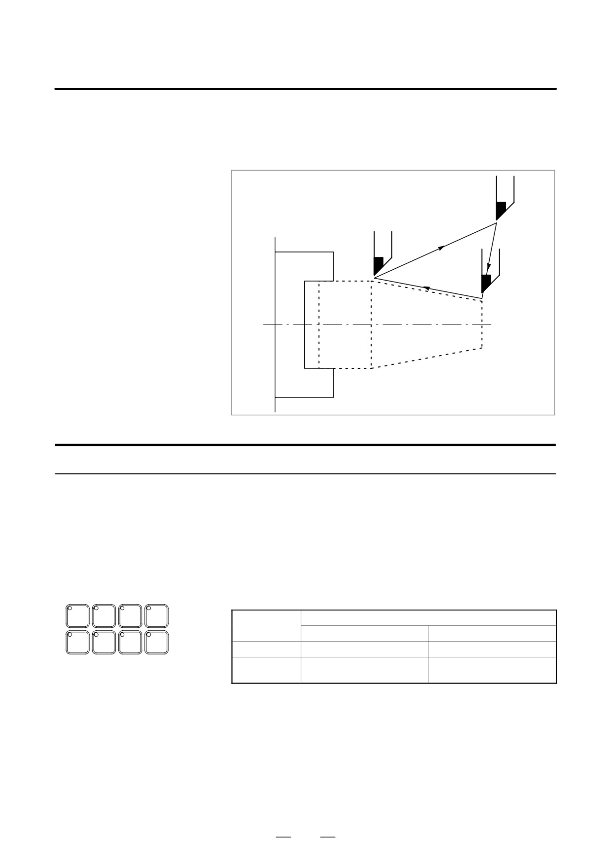
The tool is moved at the feedrate specified by a parameter regardless of
5.4
the feedrate specified in the program. This function is used for checking
DRY RUN
the movement of the tool under the state that the workpiece is removed
from the table.
Tool
ÇChuckÇÇ
ÇÇÇÇÇ
ÇÇÇÇÇ
ÇÇÇ
ÇÇÇ
ÇÇÇ
ÇÇÇ
ÇÇÇ
ÇÇÇÇÇ
ÇÇÇÇÇ
ÇÇÇÇÇ
Fig. 5.4 Dry run
Procedure for Dry Run
Press the dry run switch on the machine operator’s panel during
automatic operation. The tool moves at the feedrate specified in a
parameter. The rapid traverse switch can also be used for changing
the feedrate. Refer to the appropriate manual provided by the
machine tool builder for dry run.
Explanation
D Dry run feedrate
The dry run feedrate changes as shown in the table below according to the
rapid traverse switch and parameters.
SINGLE
OPT
BLOCK
MC
Rapid traverse
Program command
BLOCK
STOP
SKIP
LOCK
button
Rapid traverse
Feed
DRY
RUN
MST
WORK
LOCK
LIGHT
ON
Rapid traverse rate
Dry run feedrate×JVmax *2)
OFF
Dry run speed JV,or rapid
Dry run feedrate JV
traverse rate *1)
Max. cutting feedrate
Setting by parameter No. 1422
Rapid traverse rate
Setting by parameter No. 1420
Dry run feedrate
Setting by parameter No. 1410
JV: Jog feedrate override
*1) Dry run feedrate x JV when parameter RDR (bit 6 of No. 1401) is
1. Rapid traverse rate when parameter RDR is 0.
*2) Clamped to the maximum cutting feedrate
JVmax: Maximum value of jog feedrate override
557
5. TEST OPERATION
OPERATION
B-63524EN/01
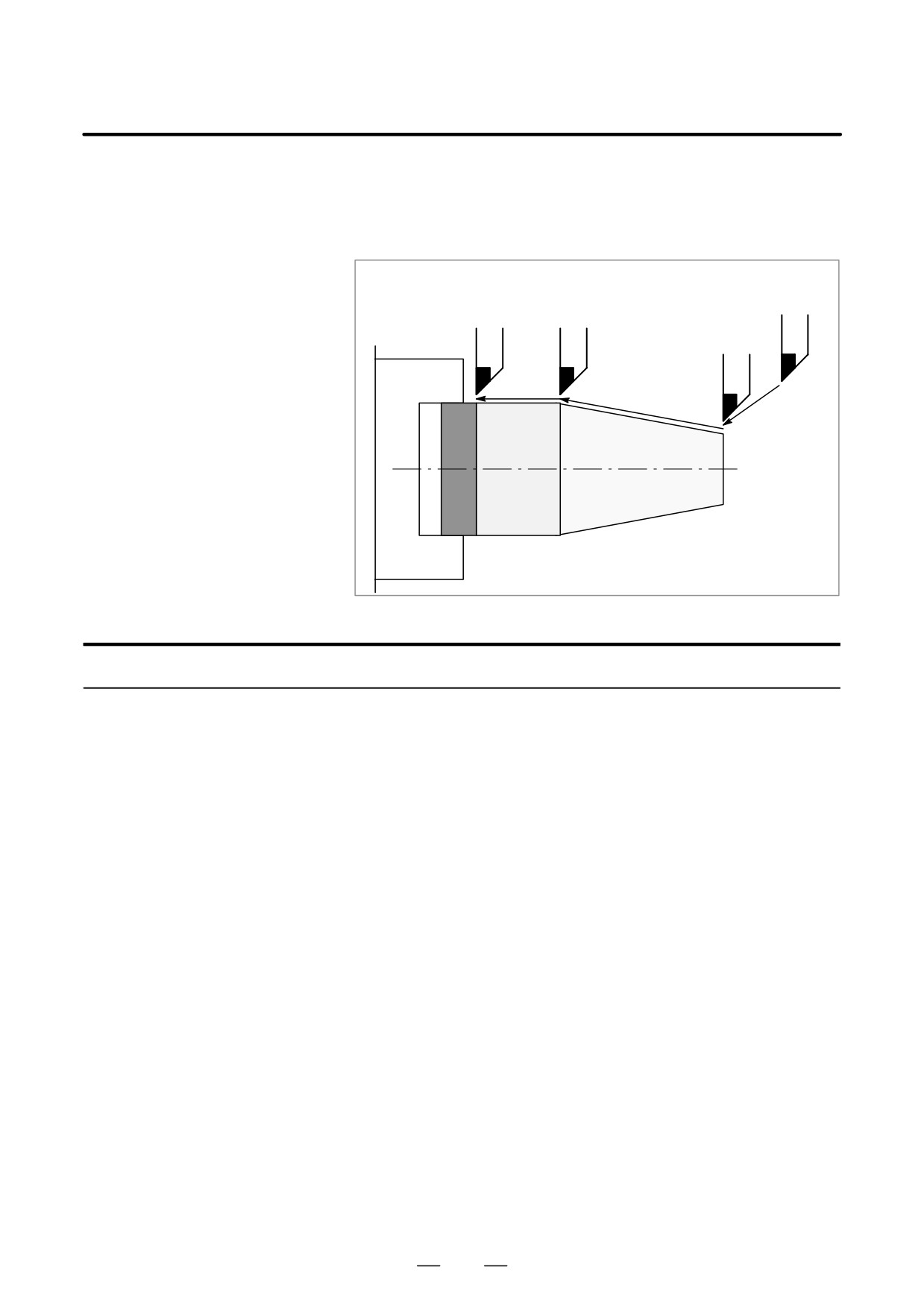
Pressing the single block switch starts the single block mode. When the
5.5
cycle start button is pressed in the single block mode, the tool stops after
SINGLE BLOCK
a single block in the program is executed. Check the program in the single
block mode by executing the program block by block.
Cycle start
Cycle start
Cycle start
Cycle start
Tool
ÇÇÇÇÇ
Stop
Stop
Stop
ÇÇÇÇÇ
Stop
ÇÇÇ
ÇÇÇ
Workpiece
ÇÇÇ
ÇÇÇ
ÇÇÇ
ÇÇÇÇÇ
ÇÇÇÇÇ
ÇÇÇÇÇ
Single block
Procedure for Single Block
1
Press the single block switch on the machine operator’s panel. The
execution of the program is stopped after the current block is
executed.
2
Press the cycle start button to execute the next block. The tool stops
after the block is executed.
Refer to the appropriate manual provided by the machine tool builder
for single block execution.
558
B-63524EN/01
OPERATION
5. TEST OPERATION
Explanation
D Reference position
If G28 to G30 are issued, the single block function is effective at the
return and single block
intermediate point.
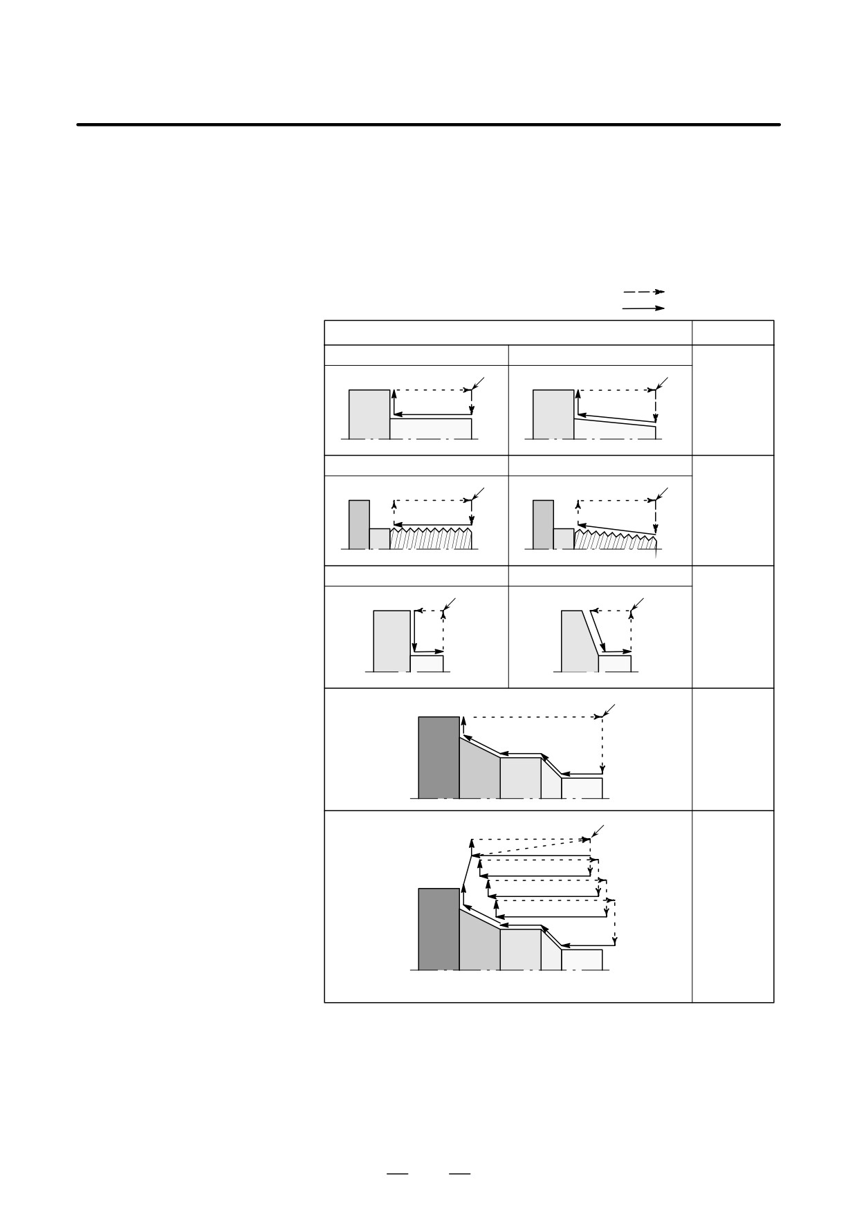
D Single block during a
In a canned cycle, the single block stop points are as follows.
canned cycle
Rapid traverse
S
: Single block
Cutting feed
Tool path
Explanation
lG90
Straight cutting cycle
Taper cutting cycle
Tool path 1
(Outer/inner turning cycle)
S
S
to 4 is as-
4
4
sumed as
1
1
3
3
2
2
one cycle.
After 4 is fin-
ished, a stop
is made.
lG92
Straight threading cycle
Taper threading cycle
Tool path 1
(Threading cycle)
S
S
to 4 is as-
4
4
sumed as
1
1
3
3
2
2
one cycle.
After 4 is fin-
ished, a stop
is made.
lG94
Straight end surface cutting cycle
Taper end surface cutting cycle
(End surface turning cycle)
S
S
Tool path 1
1
1
to 4 is as-
2
4
4
sumed as
2
one cycle.
3
3
After 4 is fin-
ished, a stop
is made.
lG70
S
7
(Finishing cycle)
Tool path 1
6
to 7 is as-
5
4
1
sumed as
3
one cycle.
2
After 7 is fin-
ished, a stop
is made.
lG71
S
(Outer surface rough
4
Each tool
3
20
1
machining cycle)
2
path 1 to 4,5
G72
8
7
6
5
to 8,9 to 12,
(End surface rough machining
11
12
9
13 to 16 and
cycle)
10
19
17 to 20 is
15
16
13
14
assumed as
17
one cycle.
18
After each
cycle is fin-
ished, a stop
This figure shows the case for G71. G72 is the same.
is made.
Fig. 5.5 Single block during canned cycle (1/2)
559
5. TEST OPERATION
OPERATION
B-63524EN/01
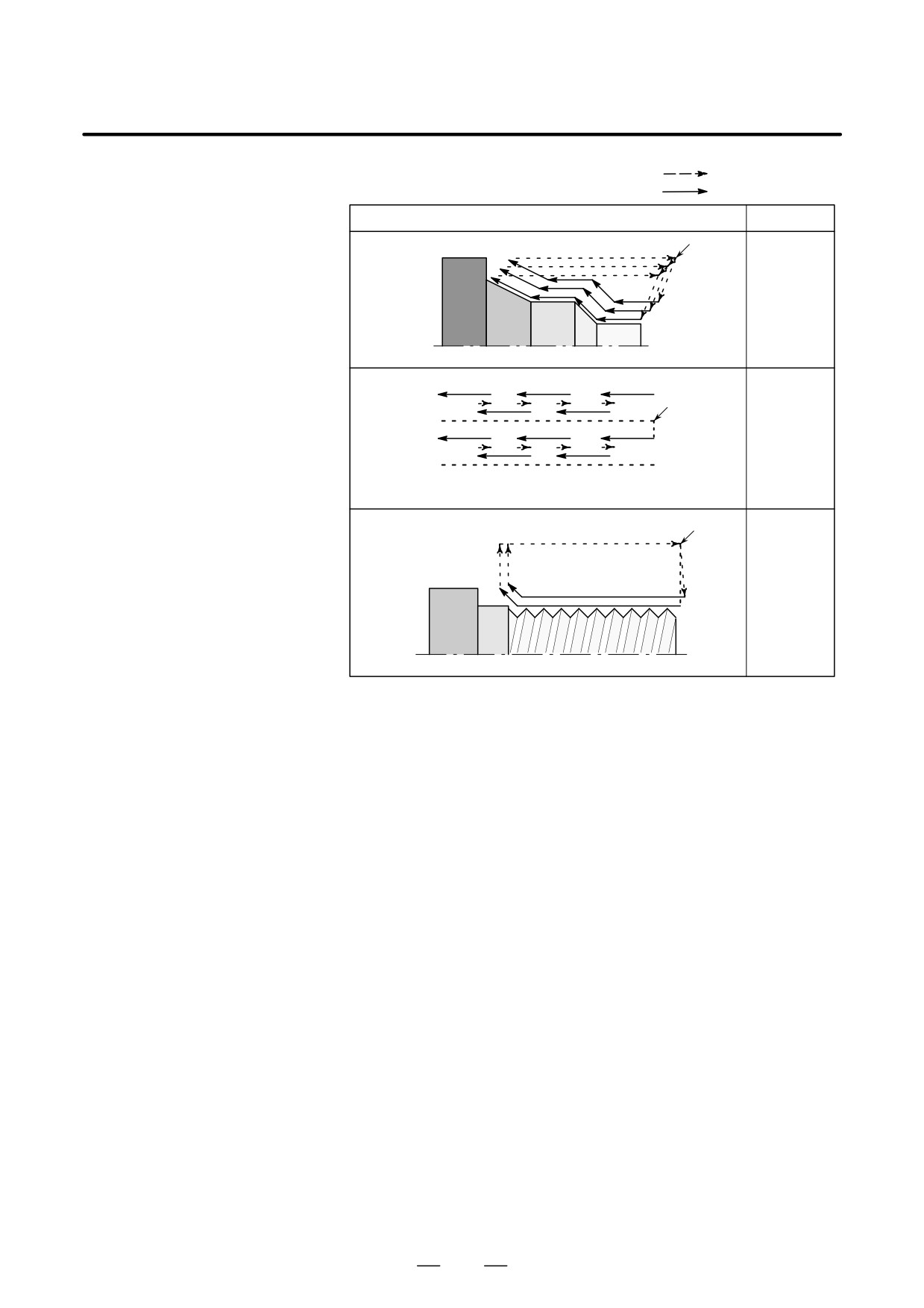
Rapid traverse
S
: Single-block stop
Cutting feed
Tool path
Explanation
lG73
S
6
Tool path 1
(Closed-loop cutting cycle)
to 6 is as-
5
4
1
sumed as
3
2
one cycle.
After 10 is
finished, a
stop is
made.
lG74
9
5
1
(End surface cutting-off cycle)
Tool path 1
8
7
6
4
3
2
S
G75
to 10 is as-
(Outer/inner surface cutting-off
sumed as
10
cycle)
one cycle.
After 10 is
finished, a
This figure shows the case for G74. G75 is the same.
stop is
made.
lG76
S
(Multiple repetitive threading cycle)
4
Tool path 1
to 4 is as-
1
3
sume as
one cycle.
2
After 4 is fin-
ished, a stop
is made.
Fig. 5.5 Single block during canned cycle (2/2)
D Subprogram call and
Single block stop is not performed in a block containing M98P_;. M99;
single block
or G65.
However, single block stop is even performed in a block with M98P_ or
M99 command, if the block contains an address other than O, N or P.
560
B-63524EN/01
OPERATION
5. TEST OPERATION
D Special single-block
Two-path control supports a single-block command signal for each of
control
tool posts 1 and 2. Single-block stop can thus be specified for the
automatic operation program for each tool post. Note, however, that when
the single-block command signals for both tool posts 1 and 2 are turned
on, the tools may stop at different positions according to the command
programs.
The special single-block control function eliminates such a difference by
applying feed hold to a tool post when the other tool post enters
single-block stop mode.
The special single-block control function is enabled when bit 6 (DSB) of
parameter No. 8100 is set to 1.
The single-block command signals for tool posts 1 and 2 are effective
even when the special single-block control function is used.
When tool post 1 or 2 is placed in the single-block mask state or feed-hold
mask state by a threading or custom macro program, the tool is not
stopped until the mask state is terminated.
The tool posts are not synchronized. Therefore, if the following programs
are executed, feed hold is applied to tool post 2 upon the completion of
X10.0 for tool post 1, but the tool of tool post 2 is not stopped exactly at
X10.0.
Tool post 1
Tool post 2
O0001 ;
O0002 ;
G50 X0 ;
G50 X0 ;
G01 X10. F100 ;
G01 X20. F100 ;
G01 X20. ;
561
6. SAFETY FUNCTIONS
OPERATION
B-63524EN/01
SAFETY FUNCTIONS
6
To immediately stop the machine for safety, press the Emergency stop
button. To prevent the tool from exceeding the stroke ends, Overtravel
check and Stroke check are available. This chapter describes emergency
stop, overtravel check, and stroke check.
562

B-63524EN/01
OPERATION
6. SAFETY FUNCTIONS
If you press Emergency Stop button on the machine operator’s panel, the
6.1
machine movement stops in a moment.
EMERGENCY STOP
Red
EMERGENCY STOP
Fig. 6.1 Emergency stop
This button is locked when it is pressed. Although it varies with the
machine tool builder, the button can usually be unlocked by twisting it.
Explanation
EMERGENCY STOP interrupts the current to the motor.
Causes of trouble must be removed before the button is released.
563
6. SAFETY FUNCTIONS
OPERATION
B-63524EN/01
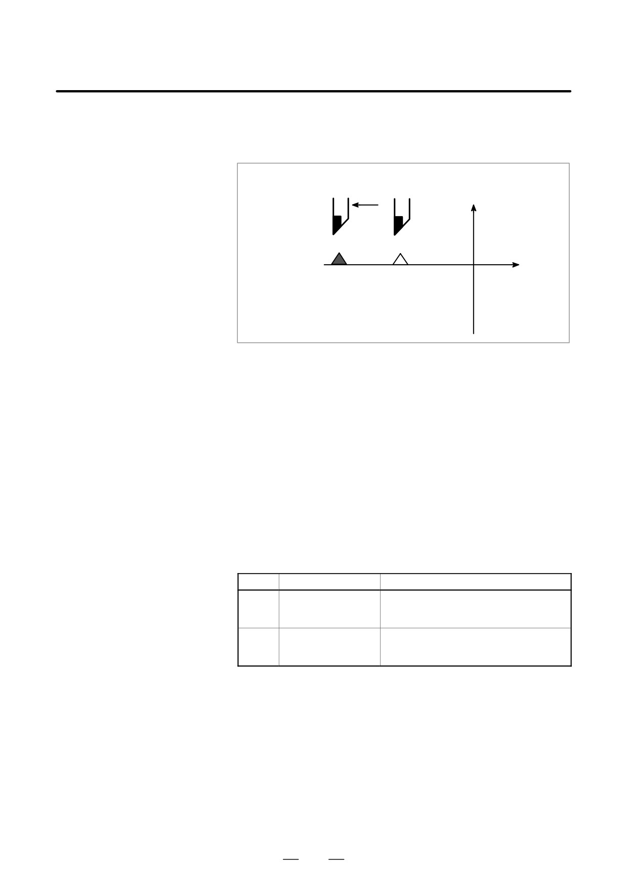
When the tool tries to move beyond the stroke end set by the machine tool
6.2
limit switch, the tool decelerates and stops because of working the limit
OVERTRAVEL
switch and an OVER TRAVEL is displayed.
Deceleration and stop
Y
X
Stroke end
Limit switch
Fig. 6.2 Overtravel
Explanation
D Overtravel during
When the tool touches a limit switch along an axis during automatic
automatic operation
operation, the tool is decelerated and stopped along all axes and an
overtravel alarm is displayed.
D Overtravel during
In manual operation, the tool is decelerated and stopped only along the
manual operation
axis for which the tool has touched a limit switch. The tool still moves
along the other axes.
Press the reset button to reset the alarm after moving the tool to the safety
D Releasing overtravel
direction by manual operation. For details on operation, refer to the
operator’s manual of the machine tool builder.
D Alarm
No.
Message
Description
The tool has exceeded the hardware-spe-
506
Overtravel: +n
cified overtravel limit along the positive nth
axis (n: 1 to 8).
The tool has exceeded the hardware-spe-
507
Overtravel: -n
cified overtravel limit along the negative nth
axis (n: 1 to 8).
564
B-63524EN/01
OPERATION
6. SAFETY FUNCTIONS
There areas which the tool cannot enter can be specified with stored stroke
6.3
check 1, stored stroke check 2, and stored stroke check 3.
STORED STROKE
CHECK
ÇÇÇÇÇÇÇÇÇÇÇÇÇÇÇÇÇÇÇÇ
ÇÇÇÇÇÇÇÇÇÇÇÇÇÇÇÇÇÇÇÇ
ÇÇÇÇÇÇÇÇÇÇÇÇÇÇÇÇÇÇÇÇ
ÇÇÇÇÇÇÇÇÇÇÇÇÇÇÇÇÇÇÇÇ
ÇÇÇÇÇÇÇÇÇÇÇÇÇÇÇÇÇÇÇÇ
Stored stroke limit 3
ÇÇÇÇÇÇÇÇÇÇÇÇÇÇÇÇÇÇÇÇ
Stored stroke limit 2ÇÇÇÇÇ
ÇÇÇÇÇÇÇÇ
ÇÇ
ÇÇÇÇÇÇÇÇÇÇÇÇÇÇÇÇÇÇÇÇ
ÇÇÇÇÇÇÇÇÇÇÇÇÇÇÇÇÇÇÇÇ
ÇÇÇÇÇÇÇÇÇÇÇÇÇÇÇÇÇÇÇÇ
ÇÇÇÇÇÇÇÇÇÇÇÇÇÇÇÇÇÇÇÇ
ÇÇÇÇÇÇÇÇÇÇÇÇÇÇÇÇÇÇÇÇ
ÇÇÇÇÇÇÇÇÇÇÇÇÇÇÇÇÇÇÇÇ
ÇÇ:Forbidden area for the tool
ÇÇ
Fig. 6.3 (a) Stroke check
When the tool exceeds a stored stroke limit, an alarm is displayed and the
tool is decelerated and stopped.
When the tool enters a forbidden area and an alarm is generated, the tool
can be moved in the reverse direction from which the tool came.
Explanation
D Stored stroke check 1
Parameters (Nos. 1320, 1321 or Nos. 1326, 1327) set boundary. Outside
the area of the set limits is a forbidden area. The machine tool builder
usually sets this area as the maximum stroke.
D Stored stroke check 2
Parameters (Nos. 1322, 1323) or commands set these boundaries. Inside
(G22, G23)
or outside the area of the limit can be set as the forbidden area. Parameter
OUT (No. 1300#0) selects either inside or outside as the forbidden area.
In case of program command a G22 command forbids the tool to enter the
forbidden area, and a G23 command permits the tool to enter the
forbidden area. Each of G22; and G23; should be commanded
independently of another commands in a block.
The command below creates or changes the forbidden area:
565
6. SAFETY FUNCTIONS
OPERATION
B-63524EN/01
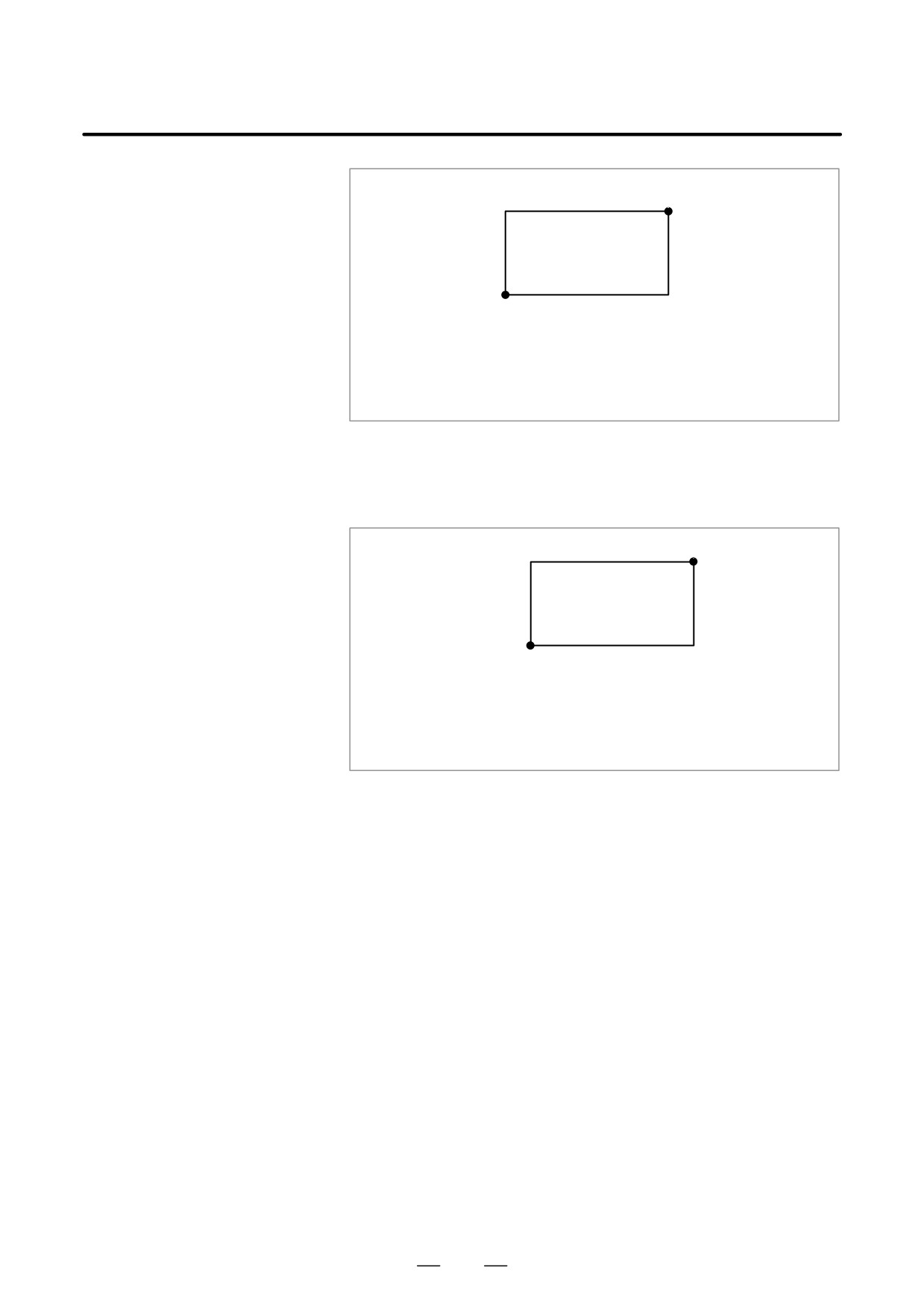
G 22X_Z_I_K_;
A(X,Z)
B(I,K)
X>I,Z>K
X-I>ζ
Z-K>ζ
ζ is the distance the tool travels in 8 ms. It is 2000 in least
command increments when the feedrate is 15 m/min.
Fig. 6.3 (b) Creating or changing the forbidden area using a program
When setting the area by parameters, points A and B in the figure below
must be set.
A(X1,Z1)
B(X2,Z2)
X1>X 2 , Z1>Z2
X1-X2> ζ
Z1-Z2> ζ
ζ is the distance the tool travels in 8 ms. It is 2000 in least
command increments when the feedrate is 15 m/min.
Fig. 6.3 (c) Creating or changing the forbidden area using a parameters
In stored stroke check 2, even if you mistake the order of the coordinate
value of the two points, a rectangular, with the two points being the
apexes, will be set as the area.
When you set the forbidden area X1, Z1, X2, and Z2 through parameters
(Nos. 1322, 1323), the data should be specified by the distance from the
reference position in the least command increment. (Output increment)
If set the forbidden area XZIK by a G22 command, specify the data by the
distance from the reference position in the least input increment (Input
increment.) The programmed data are then converted into the numerical
values in the least command increment, and the values are set as the
parameters.
D Stored stroke check 3
Set the boundary with parameters No. 1324 and 1325. The area inside the
boundary becomes the forbidden area.
566
B-63524EN/01
OPERATION
6. SAFETY FUNCTIONS
D Checkpoint for the
The parameter setting or programmed value (XZIK) depends on which
forbidden area
part of the tool or tool holder is checked for entering the forbidden area.
Confirm the checking position (the top of the tool or the tool chuck) before
programming the forbidden area.
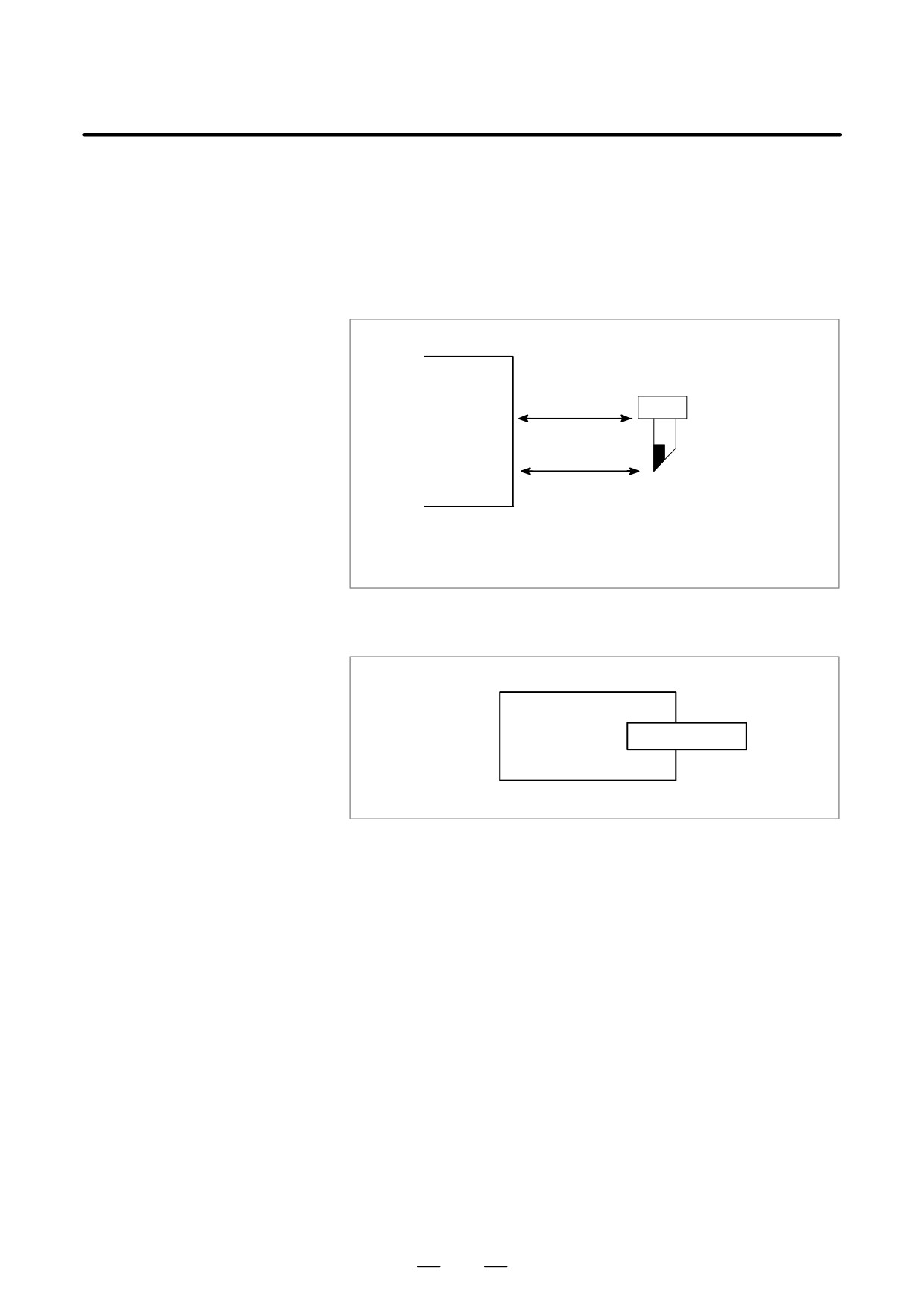
If point C (The top of the tool) is checked in Fig. 6.3 (d) , the distance “c”
should be set as the data for the stored stroke limit function. If point D
(The tool chuck) is checked, the distance “d” must be set.
d
D
c
C
The position of the
tool after reference
Area boundary
position return
Fig. 6.3 (d) Setting the forbidden area
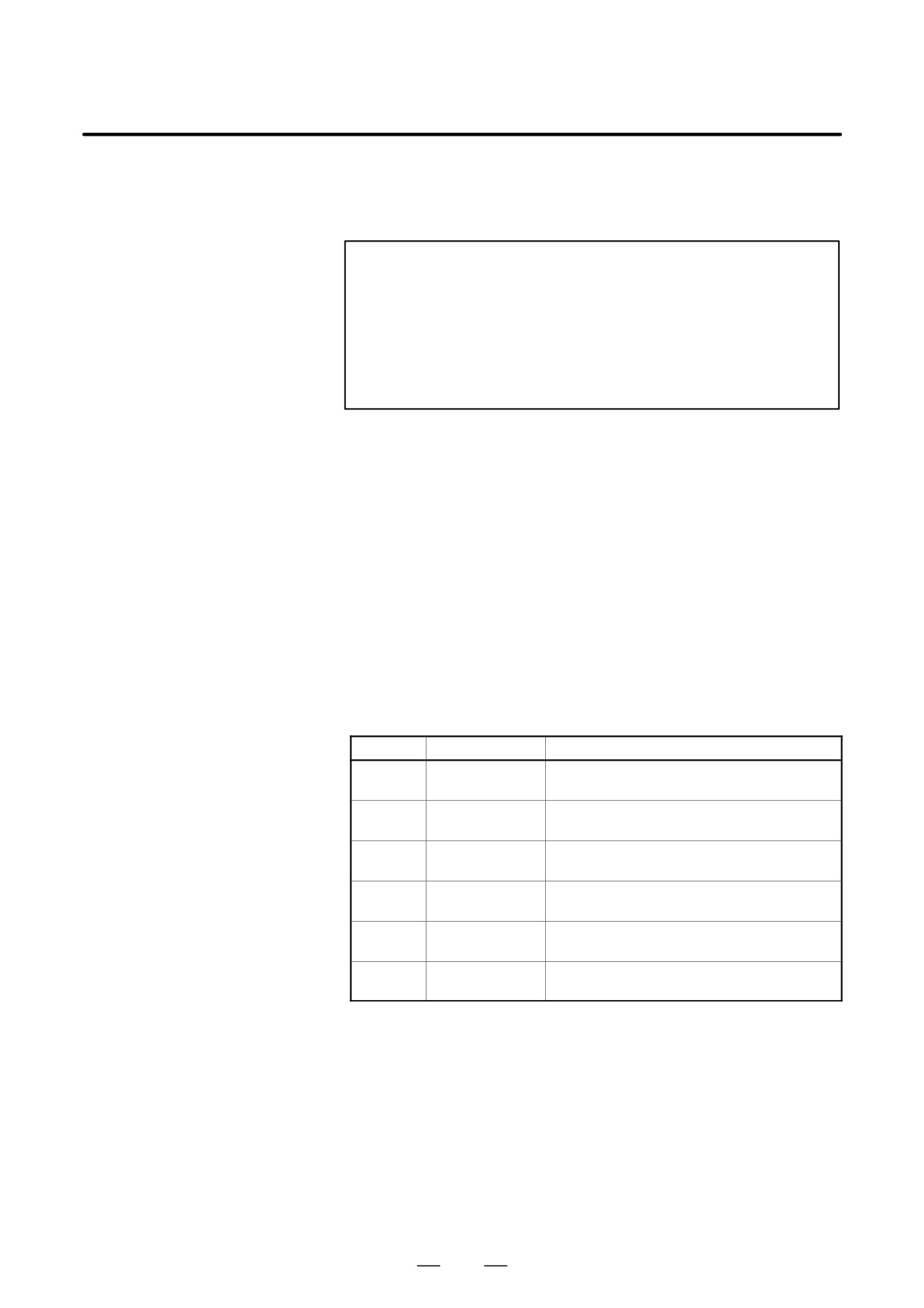
D Forbidden area over-
Area can be set in piles.
lapping
ÇÇÇÇÇÇÇÇÇÇ
Ç
ÇÇ
Ç
ÇÇÇÇÇÇ
Ç
ÇÇÇÇÇÇ
Ç
ÇÇ
ÇÇÇÇÇÇÇÇÇÇ
Fig. 6.3 (e) Setting the forbidden area over lapping
Unnecessary limits should be set beyond the machine stroke.
D Effective time for a
Each limit becomes effective after the power is turned on and manual
forbidden area
reference position return or automatic reference position return by G28
has been performed.
After the power is turned on, if the reference position is in the forbidden
area of each limit, an alarm is generated immediately. (Only in G22 mode
for stored stroke limit 2).
When the tool has become unmovable in the forbidden area, push the
D Releasing the alarms
emergency stop button to release the forbidden condition and move the
tool out of the forbidden area in the G23 mode; then, if the setting is
wrong, correct it and perform the reference position return again.
D Change from G23 to
When G23 is switched to G22 in the forbidden area, the following results.
G22 in a forbidden area
(1) When the forbidden area is inside, an alarm is informed in the next
move.
(2) When the forbidden area is outside, an alarm is informed immediately.
567
6. SAFETY FUNCTIONS
OPERATION
B-63524EN/01
D Setting the forbidden
For the two-path control, set a forbidden area for each tool post.
area for the two-path
control
NOTE
In setting a forbidden area, if the two points to be set arethe
same, the area is as follows:
(1)When the forbidden area is stored stroke check 1, all
areas are forbidden areas.
(2)When the forbidden area is stored stroke check 2 or
stored stroke check 3 all areas are movable areas.
D Overrun amount of
If the maximum rapid traverse rate is F (mm/min), the maximum overrun
stored stroke limit
amount, L (mm), of the stored stroke limit is obtained from the following
expression:
L (mm) = F/7500
The tool enters the specified inhibited area by up to L (mm). Bit 7 (BFA)
of parameter No. 1300 can be used to stop the tool when it reaches a point
L mm short of the specified area. In the case, the tool will not enter the
inhibited area.
D Timing for displaying
Parameter BFA (bit 7 of No. 1300) selects whether an alarm is displayed
an alarm
immediately before the tool enters the forbidden area or immediately after
the tool has entered the forbidden area.
ALram
Number
Message
Contents
500
OVER TRAVEL:
Exceeded the n-th axis (1-8) + side stored
+n
stroke limit 1.
501
OVER TRAVEL:
Exceeded the n-th axis (1-8)
* side stored
–n
stroke limit 1.
502
OVER TRAVEL:
Exceeded the n-th axis (1-8) + side stored
+n
stroke limit 2.
503
OVER TRAVEL:
Exceeded the n-th axis (1-8)
* side stored
–n
stroke limit 2.
504
OVER TRAVEL:
Exceeded the n-th axis (1-8) + side stored
+n
stroke limit 3.
505
OVER TRAVEL:
Exceeded the n-th axis (1-8)
* side stored
–n
stroke limit 3.
568
B-63524EN/01
OPERATION
6. SAFETY FUNCTIONS
The chuck-tailstock barrier function prevents damage to the machine by
6.4
checking whether the tool tip fouls either the chuck or tailstock.
CHUCK AND
Specify an area into which the tool may not enter (entry-inhibition area).
TAILSTOCK
This is done using the special setting screen, according to the shapes of
BARRIERS
the chuck and tailstock. If the tool tip should enter the set area during a
machining operation, this function stops the tool and outputs an alarm
message.
The tool can be cleared from the area only by retracting it in the direction
opposite to that in which the tool entered the area.
Setting the chuck and tailstock barriers
D Setting the shapes of the
OFFSET
1
Press the
SETTING
function key.
chuck and tailstock
2
Press the
continuous menu key. Then, press the [BARIER]
chapter selection soft key.
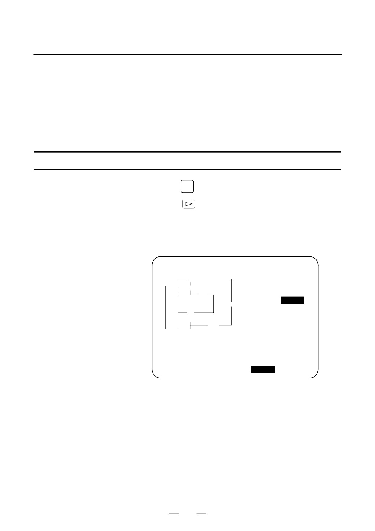
3
Pressing the page key toggles the display between the chuck barrier
setting screen and tailstock barrier setting screen.
Chuck barrier setting screen
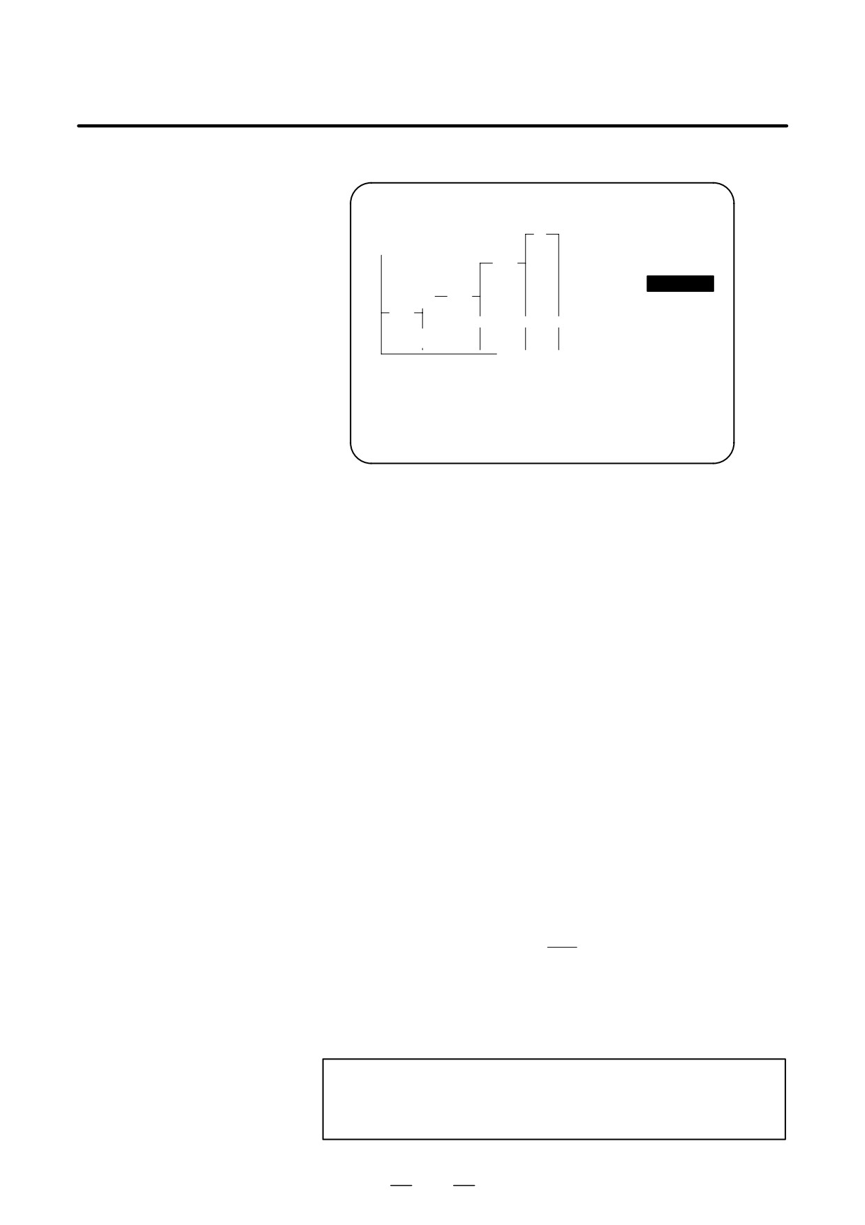
BARRIER (CHUCK)
O0000 N00000
TY=0(0:IN,1:OUT)
W1
L =
50.000
W
L1
W =
60.000
L1=
25.000
CX
W1=
30.000
L
CX=
200.000
CZ
CZ=
-100.000
ACTUAL POSITION (ABSOLUITE)
X
200.000
Z
50.000
>_
MDI **** *** ***
14:46:09
[
][ W.SHFT ][
][ BARIER
][ (OPRT) ]
569
6. SAFETY FUNCTIONS
OPERATION
B-63524EN/01
Tailstock barrier setting screen
BARRIER (TAILSTOCK)
O0000 N00000
L
L =
100.000
X
D =
200.000
L1
L1=
50.000
/D3
D1=
100.000
L2
/
L2=
50.000
/
TZ
D2=
50.000
D2
D1
D
D3=
30.000
/D3
Z
TZ=
100.000
ACTUAL POSITION (ABSOLUTE)
X
200.000
Z
50.000
>_
MDI **** *** ***
14:46:09
[ INPUT ][ +INPUT ][
SET
][
][
]
4
Position the cursor to each item defining the shape of the chuck or
tailstock, enter the corresponding value, then press the [INPUT] soft
key. The value is set. Pressing the [+INPUT] soft key after a value has
been entered adds the entered value to the current value, the new
setting being the sum of the two values.
Items CX and CZ, both on the chuck barrier setting screen, and item
TZ on the tailstock barrier setting screen can also be set in another
way. Manually move the tool to the desired position, then press the
[SET] soft key to set the coordinate(s) of the tool in the workpiece
coordinate system. If a tool having an offset other than 0 is manually
moved to the desired position with no compensation applied,
compensate for the tool offset in the set coordinate system.
Items other than CX, CZ, and TZ cannot be set by using the [SET] soft
key.
Example)
When the tool tip enters the entry-inhibition area during machining,
the function stops the movement of the tool and displays an alarm
message. Since the machine system can stop only a slight delay after
the CNC stops, the tool will actually stop moving at a point within the
specified boundary. For safety, therefore, set an area a little larger than
the determined area. The distance between the boundaries of these two
areas, L, is calculated from the following equation, based on the rapid
traverse rate.
1
L + (Rapid traverse Rate)
7500
When the rapid traverse rate is 15 m/min, for example, set an area
having a boundary 2 mm outside that of the determined area.
The shapes of the chuck and tailstock can be set using parameters No.
1330 to 1345.
CAUTION
Set G23 mode before attempting to specify the shapes of
the chuck and tailstock.
570
B-63524EN/01
OPERATION
6. SAFETY FUNCTIONS
D Reference position
1
Return the tool to the reference position along the X- and Z-axes.
return
The chuck-tailstock barrier function becomes effective only once
reference position return has been completed after power on.
When an absolute position detector is provided, reference position
return need not always be performed. The positional relationship
between the machine and the absolute position detector, however,
must be determined.
D G22, G23
1
After reference position return, specifying G22 (stored stroke limit
on) makes the entry-inhibition areas for the chuck and tailstock
effective. Specifying G23 (stored stroke limit off) disables the
function.
Even if G22 is specified, the entry-inhibition area for the tailstock can
be disabled by issuing a tailstock barrier signal.
When the tailstock is pushed up against a workpiece or separated from
the workpiece by using the miscellaneous functions, PMC signals are
used to enable or disable the tailstock setting area.
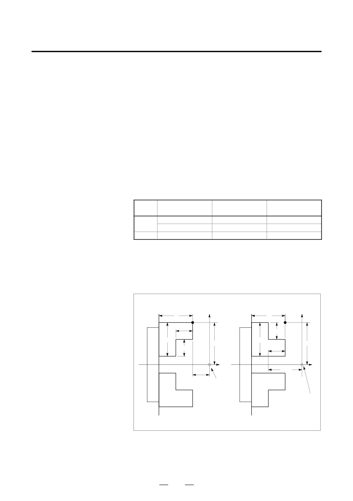
Tailstock barrier
G code
Chuck barrier
Tailstock barrier
signal
0
Effective
Effective
G22
1
Effective
Ineffective
G23
No relation
Ineffective
Ineffective
G22 is usually selected when the power is turned on. Using G23, bit 7
of parameter No. 3402, however, it can be changed to G23.
Explanations
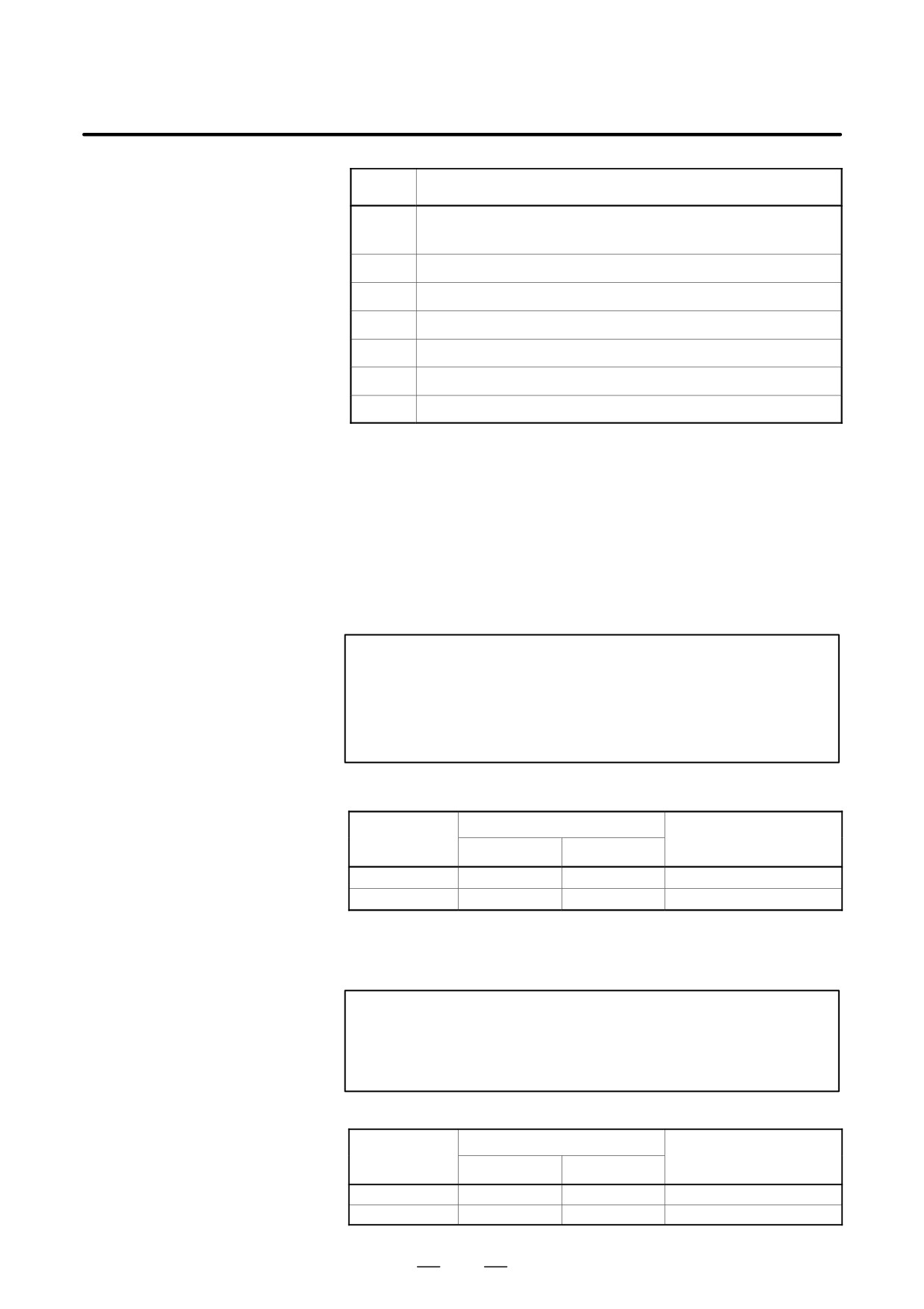
D Setting the shape of the
chuck barrier
D Chuck holding the outer
D Chuck holding the
face of a tool
inner face of a tool
X
X
L
L
ÙÙÙ
A
ÙÙÙ
A
ÙÙÙÙÙL1ÙÙ
ÙÙÙÙÙ
W1
ÙÙÙWÙÙÙ
ÙÙÙÙÙ
W
CX
CX
ÙÙÙÙÙÙÙ
ÙÙÙÙÙÙÙ
W1
L1
ÙÙÙÙÙ
ÙÙÙÙÙÙÙ
ÙÙÙ
Z
ÙÙÙ
Z
ÙÙÙÙÙ
CZ
ÙÙÙÙÙÙÙ
ÙÙÙÙÙ
Origin of work-
ÙÙÙÙÙÙÙ
piece coordi-
ÙÙÙÙÙÙÙ
ÙÙÙÙÙÙÙ
nate system
Origin of work-
ÙÙÙÙÙÙÙ
ÙÙÙÙÙ
piece coordinate
system
ÙÙÙÙÙÙÙ
ÙÙÙÙÙ
ÙÙÙ
ÙÙÙ
Note) The hatched areas indicate entry-inhibition areas.
571
6. SAFETY FUNCTIONS
OPERATION
B-63524EN/01
Symbol
Description
TY
Chuck-shape selection (0: Holding the inner face of a tool, 1: Holding the outer
face of a tool)
CX
Chuck position (along X-axis)
CZ
Chuck position (along Z-axis)
L
Length of chuck jaws
W
Depth of chuck jaws (radius)
L1
Holding length of chuck jaws
W1
Holding depth of chuck jaws (radius)
TY :
Selects a chuck type, based on its shape. Specifying 0 selects a chuck
that holds the inner face of a tool. Specifying 1 selects a chuck that
holds the outer face of a tool. A chuck is assumed to be symmetrical
about its Z-axis.
CX, CZ:
Specify the coordinates of a chuck position, point A, in the workpiece
coordinate system. These coordinates are not the same as those in the
machine coordinate system. Table 6.4 (a) lists the units used to specify
the data.
WARNING
Whether diameter programming or radius programming is
used for the axis determines the programming system.
When diameter programming is used for the axis, use
diameter programming to enter data for the axis.
Table 6.4 (a) Units
Data unit
Increment
Valid data range
system
IS-A
IS-B
Metric input
0.001 mm
0.0001 mm
-99999999 to +99999999
Inch input
0.0001 inch
0.00001 inch
-99999999 to +99999999
L, L1, W, W1:
Define the shape of a chuck. Table 6.4 (b) lists the units used to specify
the data.
WARNING
Always specify W and W1 in radius. When radius
programming is used for the Z-axis, specify L and L1 in
radius.
Table 6.4 (b) Units
Data unit
Increment
Valid data range
system
IS-A
IS-B
Metric input
0.001 mm
0.0001 mm
-99999999 to +99999999
Inch input
0.0001 inch
0.00001 inch
-99999999 to +99999999
572
B-63524EN/01
OPERATION
6. SAFETY FUNCTIONS
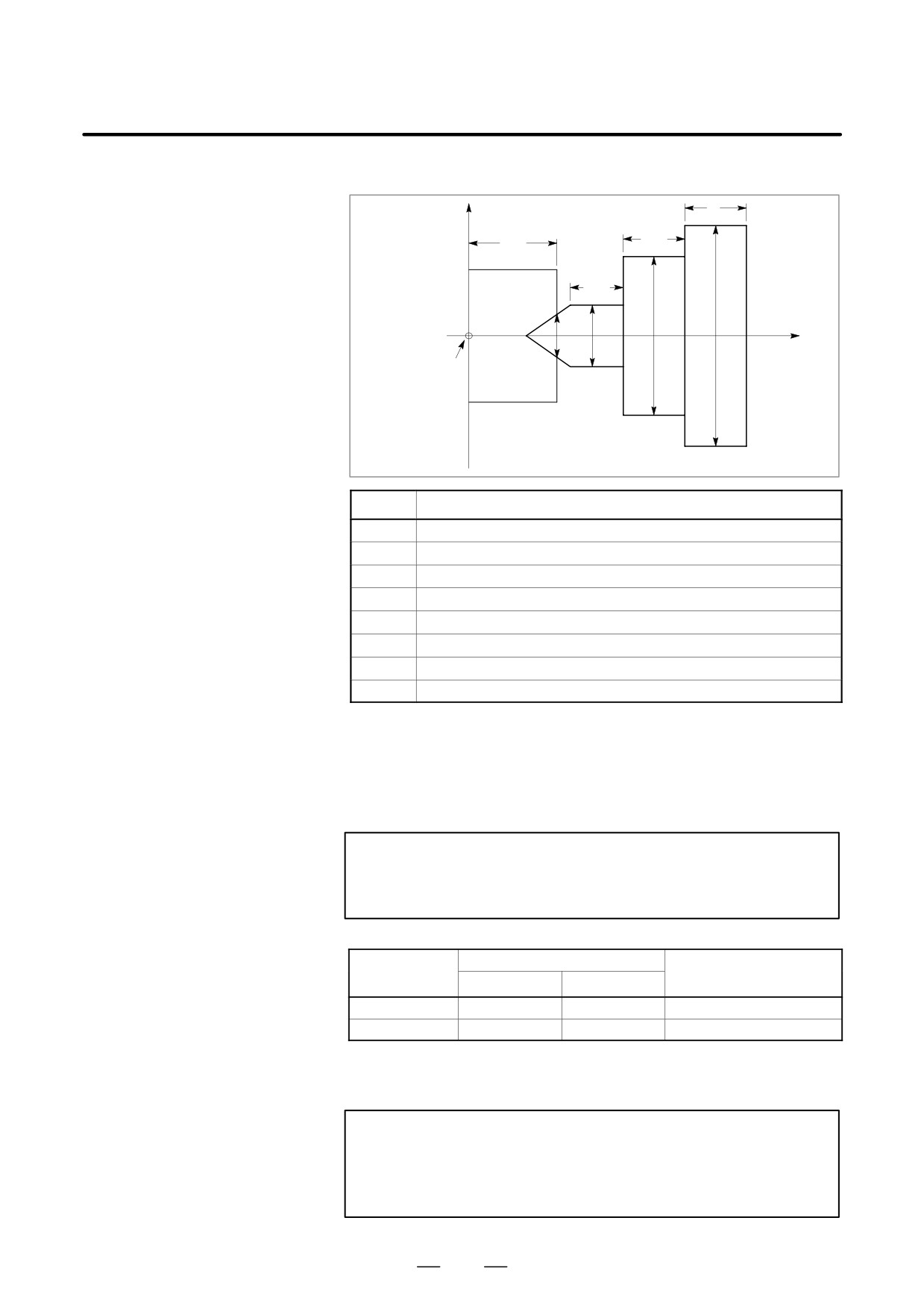
D Setting the shape of a
tailstock barrier
L
TZ
L1
L2
B
Work-
piece
Z
D3
D2
D1
D
Origin of the
workpiece
coordinate
system
Symbol
Description
TZ
Tailstock position (along the Z-axis)
L
Tailstock length
D
Tailstock diameter
L1
Tailstock length (1)
D1
Tailstock diameter (1)
L2
Tailstock length (2)
D2
Tailstock diameter (2)
D3
Tailstock diameter (3)
TZ :
Specifies the Z coordinate of the chuck position, point B, in the
workpiece coordinate system. These coordinates are not the same as
those in the machine coordinate system. Table 6.4 (c) lists the units
used to specify the data. A tailstock is assumed to be symmetrical
about its Z-axis.
WARNING
Whether diameter programming or radius programming is
used for the Z-axis determines the programming system.
Table 6.4 (c) Units
Increment
Data unit
Valid data range
system
IS-A
IS-B
Metric input
0.001 mm
0.0001 mm
-99999999 to +99999999
Inch input
0.0001 inch
0.00001 inch
-99999999 to +99999999
L, L1, L2, D, D1, D2, D3:
Define the shape of a tailstock. Table 6.4 (d) lists the units used to
specify the data.
WARNING
Always specify D, D1, D2, and D3 in diameter programming.
When radius programming is used for the Z-axis, specify L,
L1, and L2 in radius.
573
6. SAFETY FUNCTIONS
OPERATION
B-63524EN/01
Table 6.4 (d) Units
Data unit
Increment
Valid data range
system
IS-A
IS-B
Metric input
0.001 mm
0.0001 mm
-99999999 to +99999999
Inch input
0.0001 inch
0.00001 inch
-99999999 to +99999999
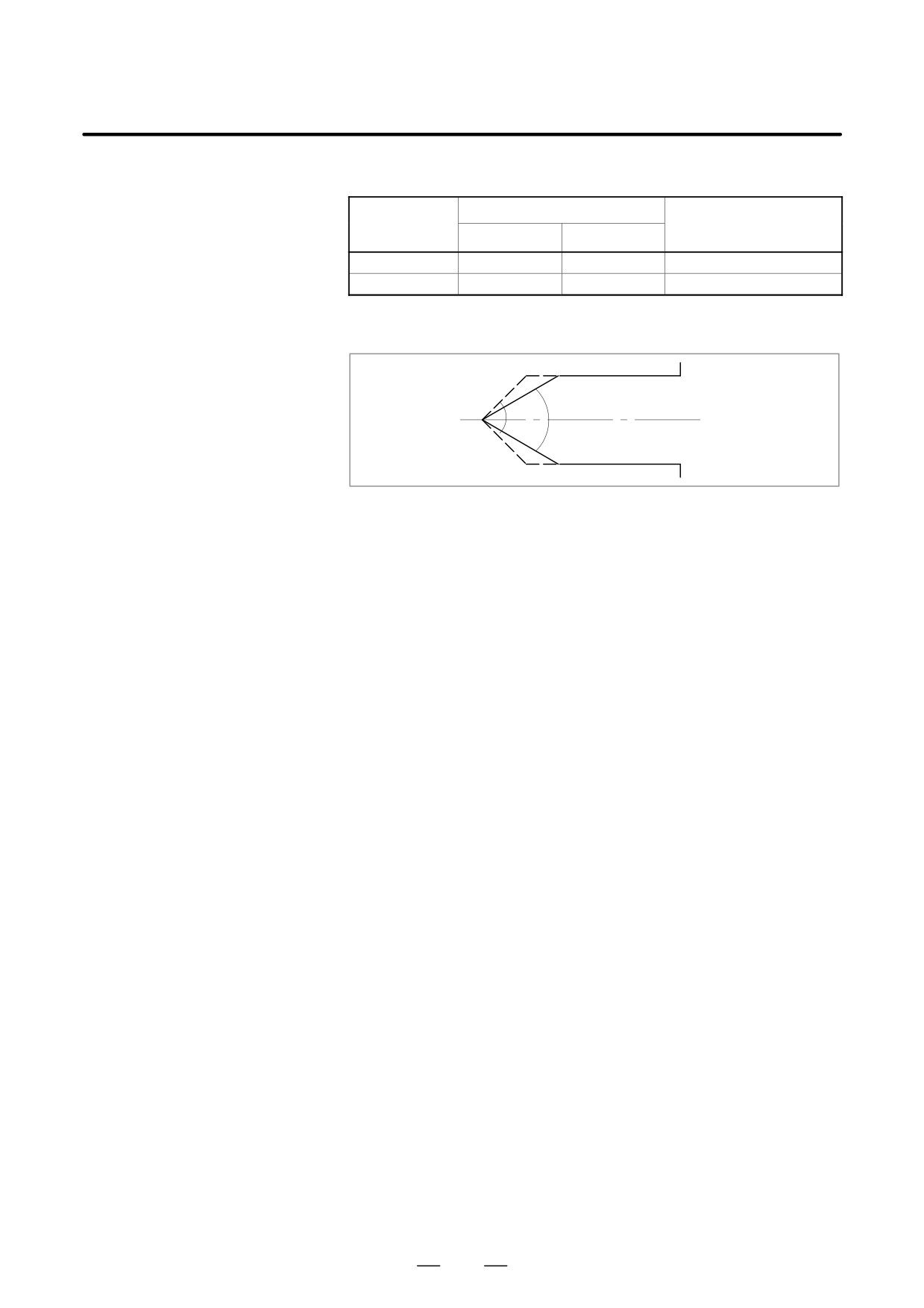
D Setting the
The tip angle of the tailstock is 60 degrees. The entry-inhibition area is
entry-inhibition area for
set around the tip, assuming the angle to be 90 degrees, as shown below.
the tailstock tip
90°
60°
Limitations
D Correct setting of an
If an entry-inhibition area is incorrectly set, it may not be possible to
entry-inhibition area
make the area effective. Avoid making the following settings:
D L < L1 or W < W1 in the chuck-shape settings.
D D2 < D3 in the tailstock-shape settings.
D A chuck setting overlapping that of the tailstock.
D Retraction from the
If the tool enters the entry-inhibition area and an alarm is issued, switch
entry-inhibition area
to manual mode, retract the tool manually, then reset the system to release
the alarm. In manual mode, the tool can be moved only in the opposite
direction to that in which the tool entered the area. The tool cannot be
moved in the same direction (further into the area) as it was travelling
when the tool entered the area.
When the entry-inhibition areas for the chuck and tailstock are enabled,
and the tool is already positioned within those areas, an alarm is issued
when the tool moves. When the tool cannot be retracted, change the
setting of the entry-inhibition areas, such that the tool is outside the areas,
reset the system to release the alarm, then retract the tool. Finally, reinstall
the original settings.
574
B-63524EN/01
OPERATION
6. SAFETY FUNCTIONS
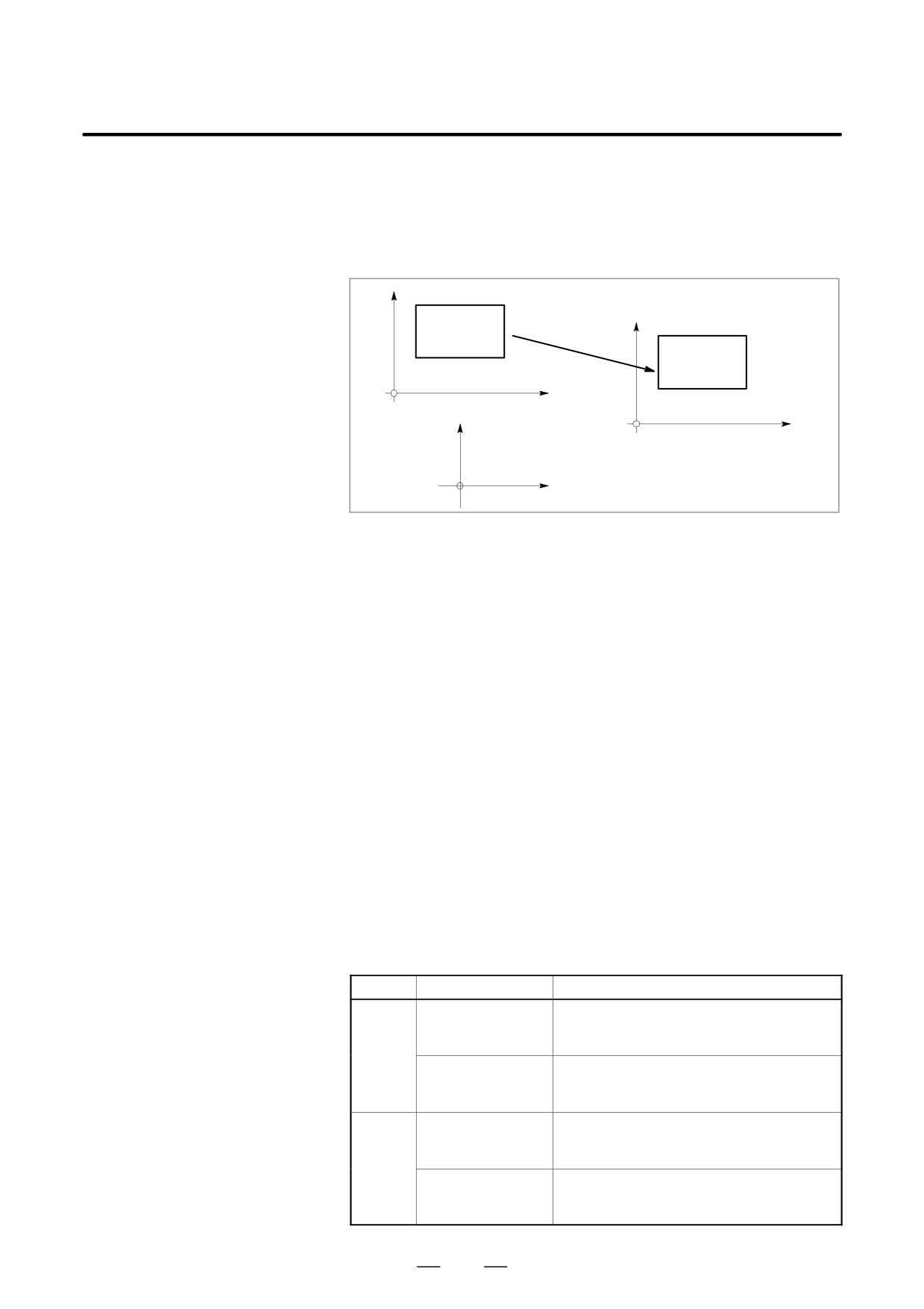
D Coordinate system
An entry-inhibition area is defined using the workpiece coordinate
system. Note the following.
1
When the workpiece coordinate system is shifted by means of a
command or operation, the entry-inhibition area is also shifted by the
same amount.
Entry-inhibi-
tion area
Entry-inhibi-
Old workpiece
tion area
coordinate system
New workpiece
coordinate system
Machine coordinate system
Use of the following commands and operations will shift the workpiece
coordinate system.
Commands:
G54 to G59, G52, G50 (G92 in G code system B or C)
Operations:
Manual handle interrupt, change in offset relative to the workpiece
reference point, change in tool offset (tool geometry compensation),
operation with machine lock, manual operation with machine absolute
signal off
2
When the tool enters an entry-inhibition area during automatic
operation, set the manual absolute signal, *ABSM, to 0 (on), then
manually retract the tool from the area. If this signal is 1, the distance
the tool moves in manual operation is not counted in the tool
coordinates in the workpiece coordinate system. This results in the
state where the tool can never be retracted from the entry-inhibition
area.
D Stored stroke limit 2
When both stored stroke limit 2 and the chuck-tailstock barrier function
are provided, the barrier takes priority over the stroke limit. Stored stroke
limit 2 is ignored.
Alarms
Number
Message
Contents
502
OVER TRAVEL: +X
The tool has entered the entry-inhibition
area during positive-direction movement
along the X-axis.
OVER TRAVEL: +Z
The tool has entered the entry-inhibition
area during positive-direction movement
along the Z-axis.
503
OVER TRAVEL: -X
The tool has entered the entry-inhibition
area during negative-direction movement
along the X-axis.
OVER TRAVEL: -Z
The tool has entered the entry-inhibition
area during negative-direction movement
along the Z-axis.
575
6. SAFETY FUNCTIONS
OPERATION
B-63524EN/01
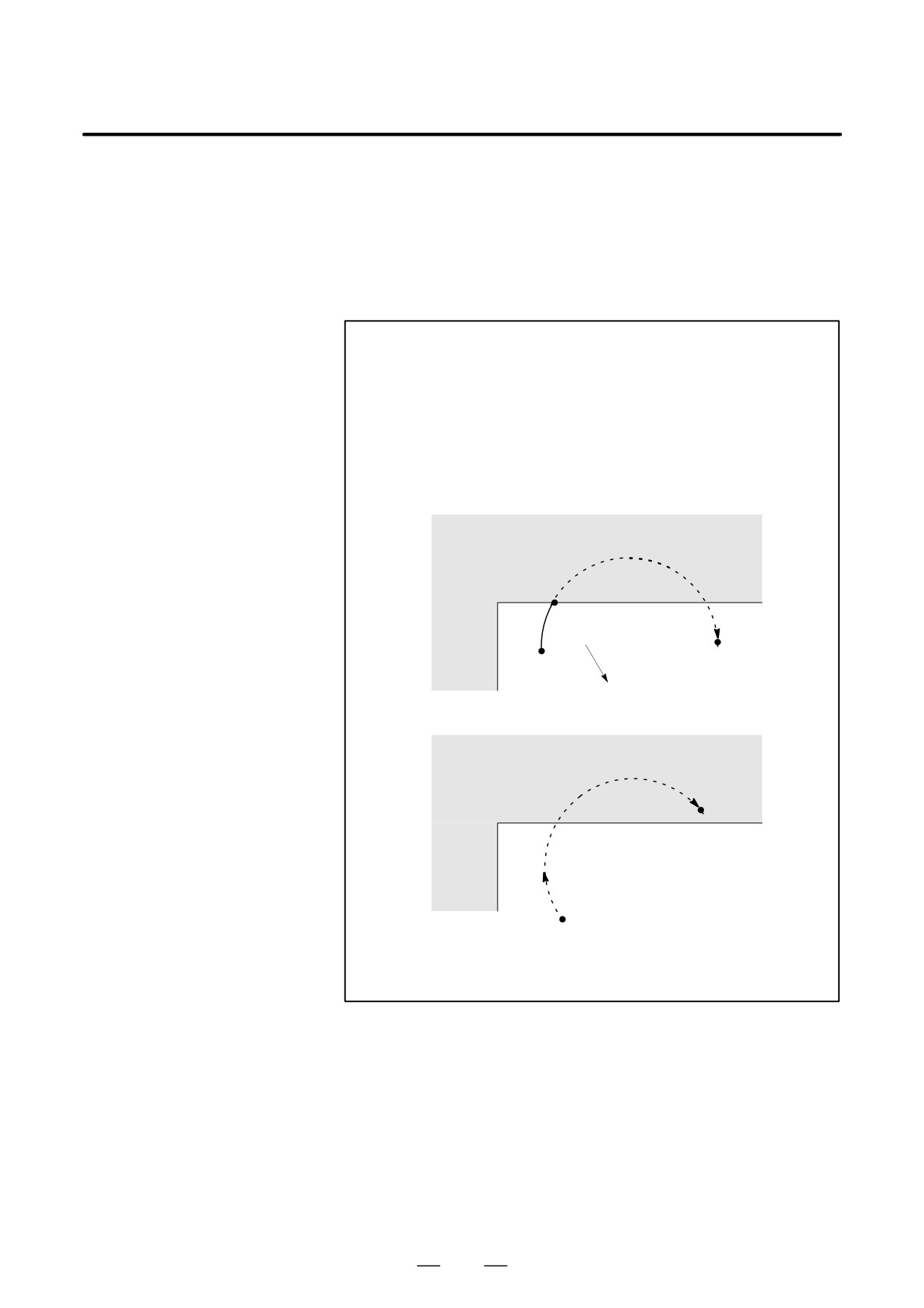
During automatic operation, before the movement specified by a given
6.5
block is started, whether the tool enters the inhibited area defined by
STROKE LIMIT
stored stroke limit 1, 2, or 3 is checked by determining the position of the
CHECK PRIOR TO
end point from the current position of the machine and a specified amount
PERFORMING
of travel. If the tool is found to enter the inhibited area defined by a stored
stroke limit, the tool is stopped immediately upon the start of movement
MOVEMENT
for that block, and an alarm is displayed.
WARNING
Whether the coordinates of the end point, reached as a
result of traversing the distance specified in each block, are
in a inhibited area is checked. In this case, the path followed
by a move command is not checked. However, if the tool
enters the inhibited area defined by stored stroke limit 1, 2,
or 3, an alarm is issued.
(See the examples below.)
Example 1)
Inhibited area defined by
stored stroke limit 1 or 2
a
End point
Start point
The tool is stopped at point a according
to stored stroke limit 1 or 2.
Inhibited area defined by
stored stroke limit 1 or 2
End point
Immediately upon movement commencing
from the start point, the tool is stopped to
enable a stroke limit check to be performed
before movement.
576
B-63524EN/01
OPERATION
6. SAFETY FUNCTIONS
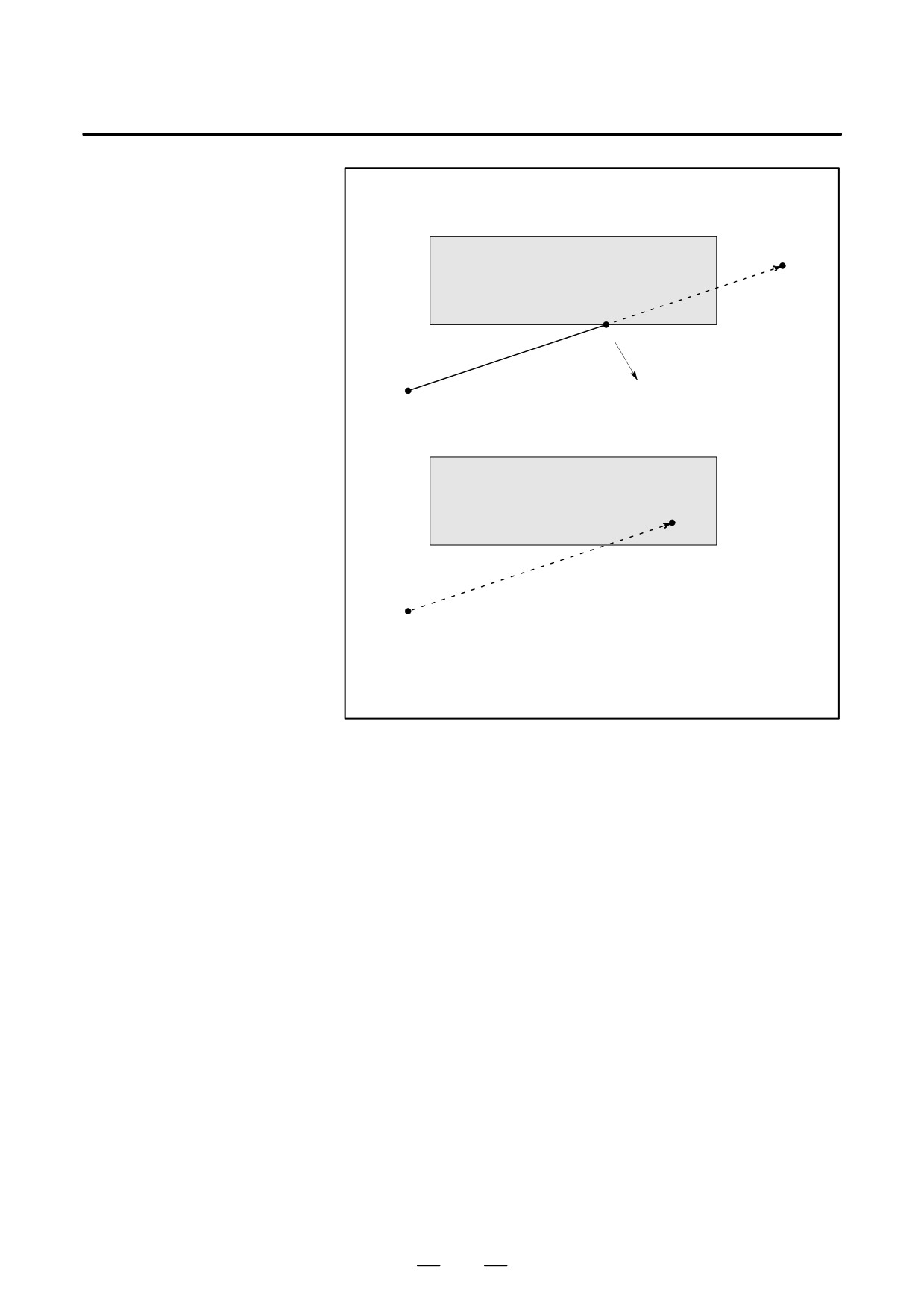
Example 2)
End point
Inhibited area defined by
stored stroke limit 2 or 3
a
The tool is stopped at point a according
Start point
to stored stroke limit 1 or 2.
Inhibited area defined by
stored stroke limit 2 or 3
End point
Immediately upon movement commencing
from the start point, the tool is stopped to
enable a stroke limit check to be performed
before movement.
Explanations
When a stroke limit check prior to movement is performed, whether to
check the movement performed by a G31 (skip) block and G37 (automatic
tool length measurement) block can be determined using NPC (bit 2 of
parameter No. 1301).
Limitations
D Machine lock
If machine lock is applied at the start of movement, no stroke limit check
made before movement is performed.
D G23
When stored stroke limit 2 is disabled (G23 mode), no check is made to
determine whether the tool enters the inhibited area defined by stored
stroke limit 2.
D Program restart
When a program is restarted, an alarm is issued if the restart position is
within a inhibited area.
D Manual intervention
When the execution of a block is restarted after manual intervention
following a feed hold
following a feed hold stop, no alarm is issued even if the end point after
stop
manual intervention is within a inhibited area.
D A block consisting of
If a block consisting of multiple operations (such as a canned cycle and
multiple operations
exponential interpolation) is executed, an alarm is issued at the start point
of any operation whose end point falls within a inhibited area.
577

6. SAFETY FUNCTIONS
OPERATION
B-63524EN/01
D Cyrindrical interpolation
In cylindrical interpolation mode, no check is made.
mode
D Polar coordinate
In polar coordinate interpolation mode, no check is made.
interpolation mode
D Slanted axis control
When the slanted axis control option is selected, no check is made.
D Simple synchronous
In simple synchronous control, only the master axis is checked; no slave
control
axes are checked.
D Drawing
During drawing (while only drawing (no machining) is being performed),
no check is made.
D PMC axis control
No check is made for a movement based on PMC axis control.
D Chuck/tailstock barrier
No check is made for a chuck/tailstock barrier area (lathe system).
D Synchronous mixed
No check is made for an axis placed in synchronous mixed mode
mode
(two-path lathe control).
Alarm
Number
Message
Contents
506
OVER TRAVEL :
The pre-movement stroke limit check reveals
+n
that the block end point enters the prohibited
area for the positive stroke limit along the n
axis. Correct the program.
507
OVER TRAVEL :
The pre-movement stroke limit check reveals
–n
that the block end point enters the prohibited
area for the negative stroke limit along the n
axis. Correct the program.
578