FANUC MANUAL GUIDE i. OPERATOR’S MANUAL - page 26
3.MACHINING CENTER
EXAMPLE OF PROGRAMMING
B-63874EN/05
3.5.7
Entering Pocket Bottom and Side Finishing Process
3.5.7.1 Entering pocket bottom finishing cycle block
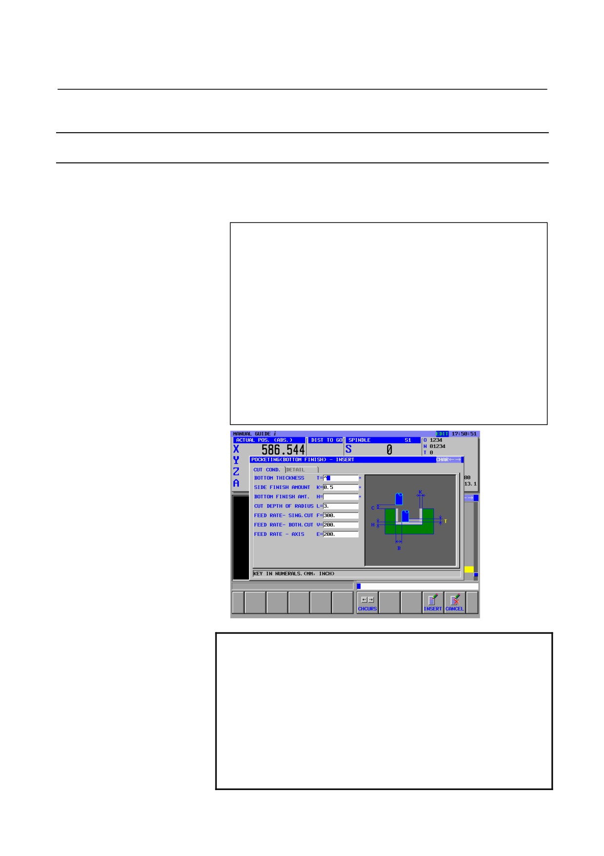
Enter 3rd process : pocket bottom finishing process by the roughing
flat end mill (T01).
Enter machining type, cutting condition and so on.
(Soft-key menu for milling cycle menu)
[CYCLE]
(INSERT MILLING CYCLE)
→
<POCKETING>
↓
<<2.POCKETING (BOTTOM FINISH)>>
[SELECT]
(POCKETING (BOTTOM FINISH) - INSERT)
<CUT COND.>
INPUT
(BOTTOM THICKNESS)
0.5 INPUT
(SIDE FINISH AMOUNT)
INPUT
(BOTTOM FINISH AMT.)
3 INPUT
(CUT DEPTH OF RADIUS)
300 INPUT
(FEED RATE - SING.CUT)
200 INPUT
(FEED RATE - BOTH.CUT)
200 INPUT
(FEED RATE - AXIS)
[INSERT]
NOTE
1 In the cycle machining data menu window, all data
excepting cutting condition data are set automatically.
However, the data entered at previously entered cycle
of same kind are copied, so you must enter the data if
you have not entered the same kind of cycle.
2 In the cycle machining data menu window, 2 tabs, <CUT
COND.> and <DETAIL>, are displayed.
In the <CUT COND.>, all data must be set. In the
<DETAIL>, all data are automatically set, so check
those data and modify them if necessary only
- 732 -
B-63874EN/05
EXAMPLE OF PROGRAMMING
3.MACHINING CENTER
3.5.7.2 Entering figure for pocket bottom finishing
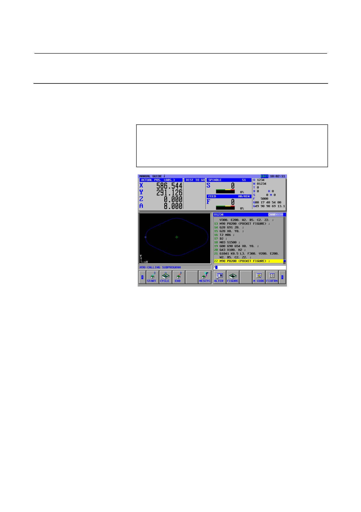
By inserting the cycle block, the window of pocketing figure is
displayed, so enter the figure for finishing. But, the former registered
figure blocks for roughing can be used, so select from the subprogram
menu.
(INSERT MILLING FIGURE)
→
<SUBPROGRAM>
↓
<<08200: POCKET FIGURE>>
[SELECT]
- 733 -
3.MACHINING CENTER
EXAMPLE OF PROGRAMMING
B-63874EN/05
3.5.7.3 Entering pocket side finishing cycle block
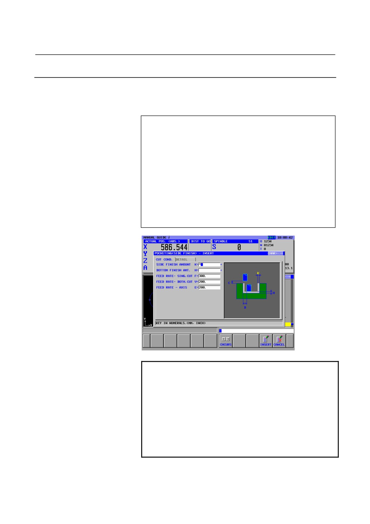
Enter 3rd process : pocket side and bottom finishing process by the
roughing flat end mill (T01).
Enter machining type, cutting condition and so on.
(Soft-key menu for milling cycle menu)
[CYCLE]
(INSERT MILLING CYCLE)
→
<POCKETING>
↓
<<3.POCKETING (SIDE FINISH)>>
[SELECT]
(POCKETING (SIDE FINISH) - INSERT)
<CUT COND.>
INPUT
(SIDE FINISH AMOUNT)
INPUT
(BOTTOM FINISH AMT.)
300 INPUT
(FEED RATE - SING.CUT)
200 INPUT
(FEED RATE - BOTH.CUT)
200 INPUT
(FEED RATE - AXIS)
[INSERT]
NOTE
1 In the cycle machining data menu window, all data
excepting cutting condition data are set
automatically. However, the data entered at
previously entered cycle of same kind are copied,
so you must enter the data if you have not entered
the same kind of cycle.
2 When you select the cycle machining type form
cycle machining menu, instead of selecting by the
cursor, you can use direct inputting of item number
and INPUT. (In this case, enter 3 INPUT)
- 734 -
B-63874EN/05
EXAMPLE OF PROGRAMMING
3.MACHINING CENTER
3.5.7.4 Entering figure for pocket side finishing
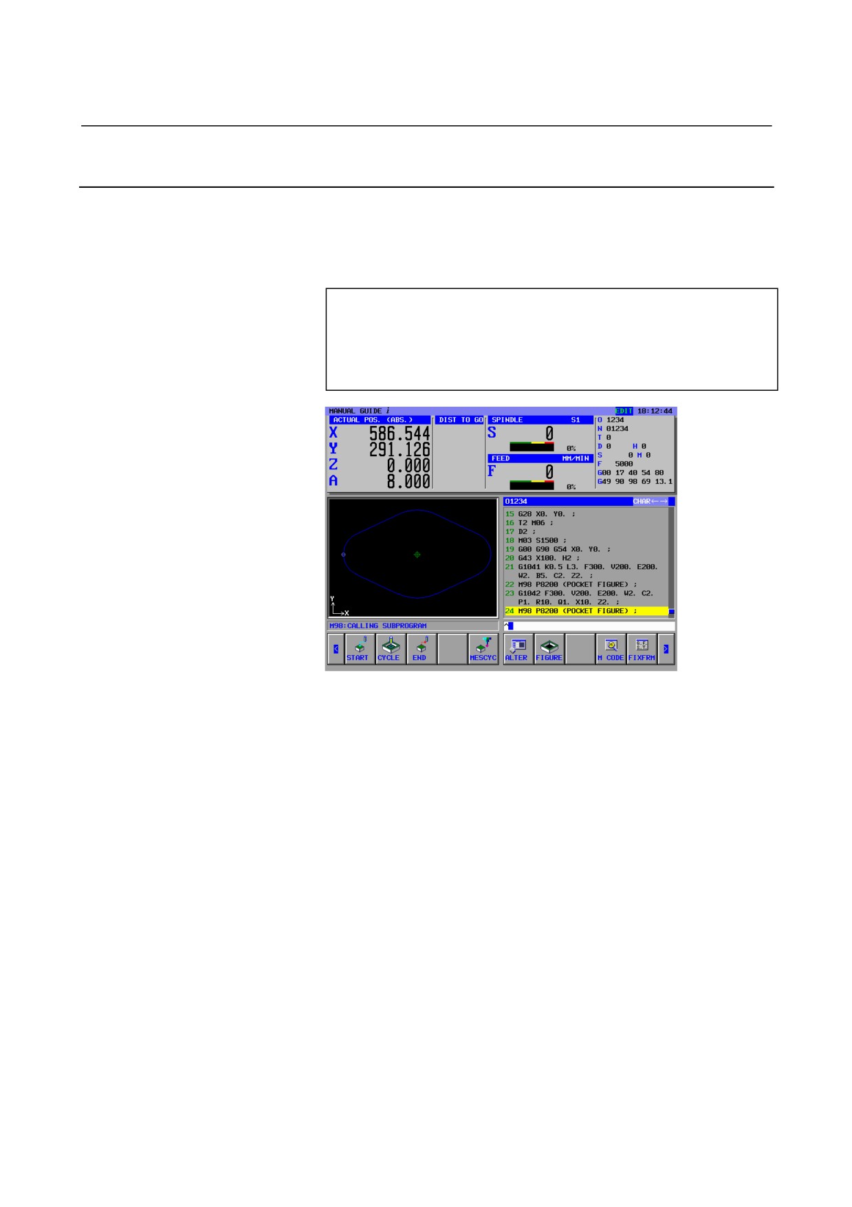
By inserting the cycle block, the window of pocketing figure is
displayed, so enter the figure for finishing. But, the former registered
figure blocks for roughing can be used, so select from the subprogram
menu.
(INSERT MILLING FIGURE)
→
<SUBPROGRAM>
↓
<<08200: POCKET FIGURE>>
[SELECT]
- 735 -

3.MACHINING CENTER
EXAMPLE OF PROGRAMMING
B-63874EN/05
3.5.8
Entering Tool Changing and Spindle Rotating Blocks for Drill
3.5.8.1
Entering in ISO-code form directly
For drilling, enter commands for operations including changing tools,
specifying the spindle, and approaching the machining start point.
G28 G91 Z0. ; INSERT
(Z-axis reference position return)
G28 G91 X0. Y0. ; INSERT
(X/Y-axis reference position return)
T03 M06 ; INSERT
(Tool change)
D3 ; INSERT
(Selecting tool data)
M03 S800 ; INSERT
(Spindle rotation)
G00 G90 G54 X0. Y0. ; INSERT (X/Y-axis approaching)
G43 Z100. H3 ; INSERT
(Z-axis approaching)
3.5.8.2
Entering by fixed form sentence menu
ISO-code form part program can be entered from the fixed form
sentence menu. The already prepared fixed form sentence as
3.MILLING START was made with entering undefined data as “?”,
so it can be used also for finishing.
(Soft-key group for milling cycle menu)
[START]
(INSERT STARTING COMMAND FOR MILLING)
<START>
↓
<<3.MILLING START>>
[INSERT]
NOTE
There may be a case that undefined value is
entered by “?” in the fixed form sentence menu, so
in this case, you need to replace the “?” by proper
value can be used in actual machining.
Place the cursor to the address with “?”, enter
numeric data, then push “ALTER”.
After altering the data, return the cursor to the EOB
at the end of the program.
- 736 -
B-63874EN/05
EXAMPLE OF PROGRAMMING
3.MACHINING CENTER
3.5.9
Entering Drilling Process
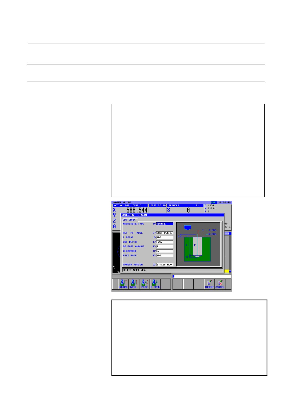
3.5.9.1 Entering drilling cycle block
Enter 4th process : Drilling by drill (T0303).
Enter machining type, cutting condition and so on.
(Soft-key menu for milling cycle menu)
[CYCLE]
(INSERT MILLING CYCLE)
<HOLE MACH.>
↓
<<2.DRILLING>>
[SELECT]
(DRILLING - INSERT)
<CUT COND.>
INPUT
(MACHINING TYPE)
INPUT
(REF.PT.MODE)
100 INPUT
(I POINT)
-20 INPUT
(CUT DEPTH)
2 INPUT
(GO PAST AMOUNT)
5 INPUT
(CLEARANCE)
100 INPUT
(FEED RATE)
[INSERT]
NOTE
1 In the cycle machining data menu window, all data
excepting cutting condition data are set
automatically. However, the data entered at
previously entered cycle of same kind are copied,
so you must enter the data if you have not entered
the same kind of cycle.
2 When you select the cycle machining type form
cycle machining menu, instead of selecting by the
cursor, you can use direct inputting of item number
and INPUT. (In this case, enter 2 INPUT)
- 737 -
3.MACHINING CENTER
EXAMPLE OF PROGRAMMING
B-63874EN/05
3.5.9.2 Entering hole position block
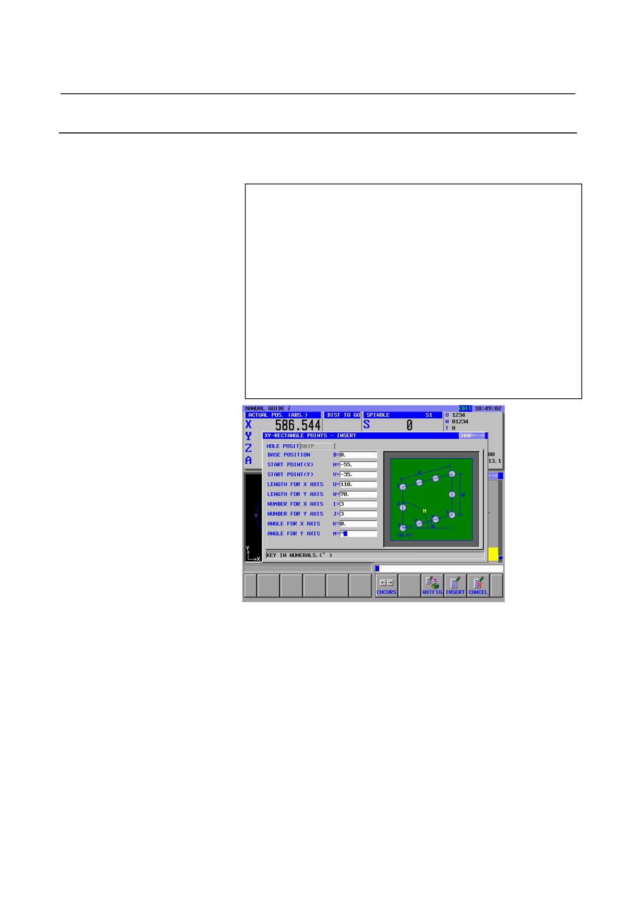
By inserting the drilling cycle block, the window of hole position
menu is displayed, so select the “YY-RECTANGLE POINTS” item.
(INSERT MILLING FIGURE)
<HOLE POSI.>
↓
↓
<<5.XY-RECTANGLE POINTS>>
[SELECT]
(XY-RECTANGLE POINTS - INSERT)
<HOLE POSIT>
0 INPUT
(BASE POSITION)
-55 INPUT
(START POINT (X))
-35 INPUT
(START POINT (Y))
110 INPUT
(LENGTH FOR X AXIS)
70 INPUT
(LENGTH FOR Y AXIS)
3 INPUT
(NUMBER FOR X AXIS)
3 INPUT
(NUMBER FOR Y AXIS)
0 INPUT
(ANGLE FOR A AXIS)
90 INPUT
(ANGLE FOR Y AXIS)
[INSERT]
- 738 -

B-63874EN/05
EXAMPLE OF PROGRAMMING
3.MACHINING CENTER
3.5.10 Operations in the “END” Menu
All necessary machining program have been entered, so enter end
procedure.
3.5.10.1 Entering in ISO-code form directly
Enter blocks for spindle stop, releasing and end M-code in ISO-code
form with G-code and son on.
M05. ; INSERT
(Spindle stop)
G00 G90 Z100.. ; INSERT
(Releasing motion)
G28 G91 Z0. ; INSERT
(Reference position return)
M06 T0 ; INSERT
(Tool changing)
M30 ; INSERT
(End M-code)
3.5.10.2 Entering by fixed form sentence menu
ISO-code form part program can be entered from the fixed form
sentence menu. But, in such a case, proper fixed form sentence must
be prepared in advance.
(Soft-key group for Milling cycle menu)
[END]
<END>
↓
<<1.END OF PROGRAM>>
[INSERT]
NOTE
There may be a case that undefined value is
entered by “?” in the fixed form sentence menu, so
in this case, you need to replace the “?” by proper
value can be used in actual machining.
- 739 -
3.MACHINING CENTER
EXAMPLE OF PROGRAMMING
B-63874EN/05
3.6
CHECKING OF THE PART PROGRAM
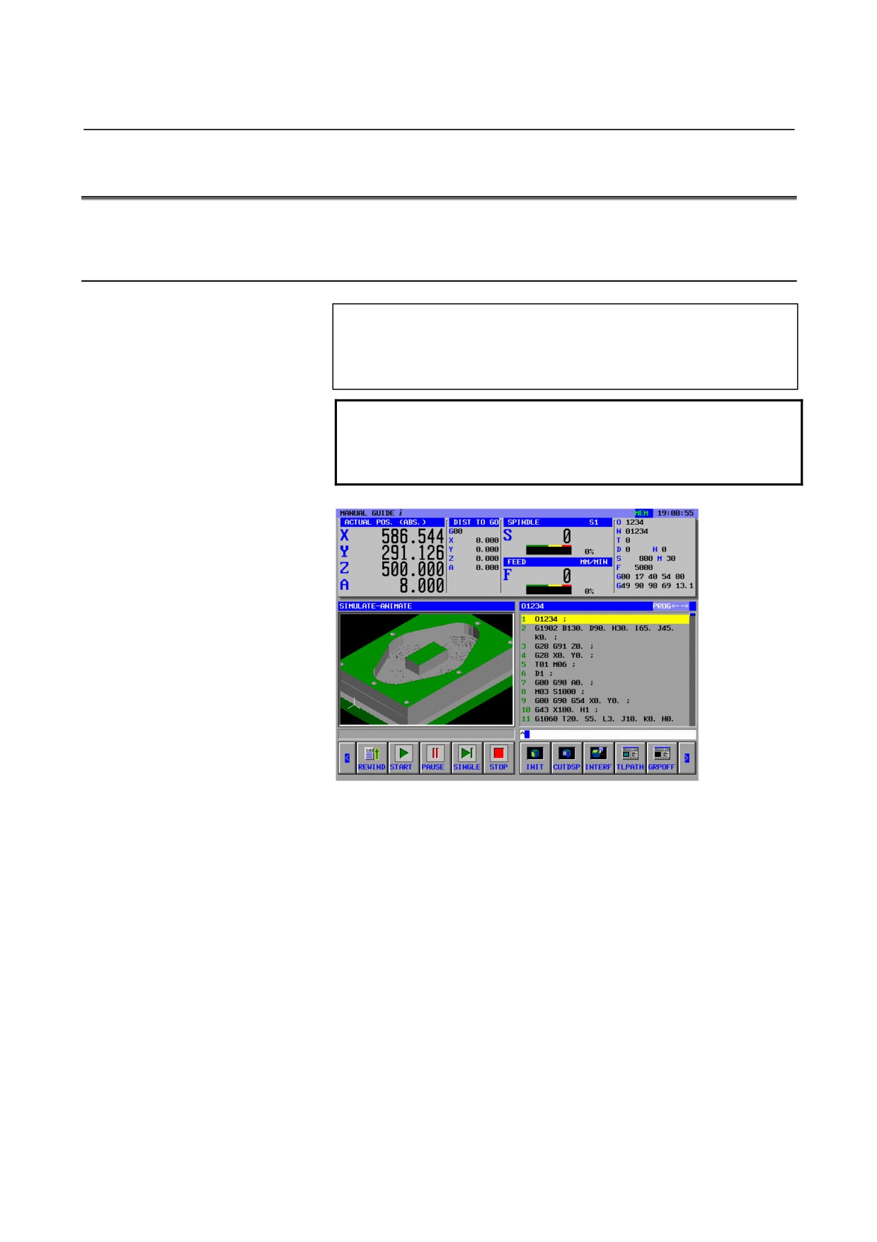
You can check the entered part program by animation.
3.6.1
Checking by Animation
Select MEM mode by using a mode-selecting switch on a machine-operating panel
[SIMLAT]
(SIMULATE - ANIMATE)
[REWIND]
[START]
NOTE
After checking by animation, in order to do other
operation, you must close the animation window by
pushing [GRPOFF] always.
- 740 -
APPENDIX

B-63874EN/05
APPENDIX
A.PARAMETERS
A
PARAMETERS
WARNING
Be sure to use the parameters set by the machine
tool builder.
If you change the setting of a parameter, the
machining program may not work correctly.
If the machining program does not work correctly,
the tool may bump against the workpiece, and the
machine may be forced to perform unnatural
machining, possibly causing damage to the tool
and/or machine, and even injuries.
- 743 -

A.PARAMETERS
APPENDIX
B-63874EN/05
A.1
REQUIRED PARAMETERS
A.1.1
Parameters Required for Basic Options
To use MANUAL GUIDE i, be sure to set the following parameters:
(1)
No.8701#4 = 1
Read of “vacant” P code macro variables is enabled.
(In Series 30i, this parameter is not necessary.)
(2)
No.3201#6 = 1
Program registration does not end with M end codes (M02, M30,
and M99).
(3)
No.8650#0 = 1
When the reset key is pressed, C-EXE passes a key code to an
application program.
(4)
No.8701#6 = 1
When the TV check is set to ON, edit operations are not regarded
as errors.
(In Series 30i, this parameter is not necessary.)
(5)
No.3112#0 (SGD) = 0
This parameter enables or disables servo waveform display.
When this parameter is set to 1, other graphic functions become
unavailable.
(In Series 30i, this parameter is not necessary.)
(6)
No.3103#3 = 1
In the FS160i and NC systems connected to a personal computer
(with an Ethernet board or HSSB board), NC software reads the
[HELP] key and changes screens even when a C-EXE screen is
being displayed.
To suppress this, set bit 3 of parameter No. 3103 to 1. The NC
software will then ignore any press of the [HELP] key while a
C-EXE screen is being displayed.
(In Series 30i, this parameter is not necessary.)
(7)
No.9000#0 = 0
This parameter is for debugging machining macro program.
And if this parameter is set to 1, Manual Guide I does not work
correctly.
(8)
No.3106#6 = 1
The function of C language executor refers to this parameter. If
this parameter is set to 1, Slant face machining does not work
correctly.
(The system checks this parameter in the case that
three-dimensional coordinate conversion is available.)
(9)
No.8650#1 = 1
During display of the screen of C language executor, Alarm
screen is not changed when the alarm occurs.
(10) No.9000#7 = 0
If this bit is set, MANUAL GUIDE i does not update the screen
display at the time of operation, and cycle execution is not
performed normally.
- 744 -
B-63874EN/05
APPENDIX
A.PARAMETERS
(11) No.8650#2 = 1
When the standard MDI key for Series 30i, please sure to set to
ON.
(In Series 16i/18i/21i, this parameter is not necessary.)
(12) No.14853#7 = 1
The program window screen in machining based on the new
specifications is used. (Scroll bar is displayed)
(In Series 16i/18i/21i, this parameter is not necessary.)
A.1.2
Parameters Required for Machining Simulation
To perform machining simulation, be sure to set the following
parameters:
(1)
No.14706≠0
Directions of the three basic axes of spindle 1
Conditions)
•
One-path T series, M series, and CNCs for complex
machining
•
Two-path T series
1)
For path 1, always set this parameter.
2)
For path 2
When bit 0 (SME) of parameter No. 27401 is set to 1
•
Three-path T series
1)
For path 1, always set this parameter.
2)
For path 2
When bit 0 (SME) of parameter No. 27401 is set to 1
3)
For path 3
When bit 0 (TME) of parameter No. 27402 is set to 1
(2)
No.14707≠0
Directions of the three basic axes of spindle 2
Conditions)
When bit 1 (SUB) of parameter No. 14702 is set to 1 (A
sub-spindle is provided.) :
•
For the one-path T series, always set this parameter.
•
For the two-path T series:
1)
For path 1
When bit 1 (FSE) of parameter No. 14701 is set to 1
2)
For path 2
When bit 1 (SSE) of parameter No. 27401 is set to 1
•
For the three-path T series:
1)
For path 1
When bit 1 (FSE) of parameter No. 14701 is set to 1
2)
For path 2
When bit 1 (SSE) of parameter No. 27401 is set to 1
3)
For path 3
When bit 1 (TSE) of parameter No. 27402 is set to 1.
- 745 -
A.PARAMETERS
APPENDIX
B-63874EN/05
A.1.3 Parameters Required for Other Options except Basic Option
(For Series 30i only)
To use other optional function except Basic option in Series 30i, be
sure to set the following parameters:
(1) No.9071 ≠ 0
This parameter is set to P-CODE Macro number of MANUAL
GUIDE i as follows.
Machining Center
:= 90
Lathe
:= 91
(2) No.9072 ≠ 0
This parameter is set to the block number for dealing with Macro
sentence continuously in Execute Macro program. MANUAL
GUIDE i recommend it to 1.
- 746 -

B-63874EN/05
APPENDIX
A.PARAMETERS
A.2 BASIC PARAMETERS
A.2.1 Settings for the Color Palette for Screen Display (No.2)
These parameters set the colors used to display screen components.
Color setting data for a screen display color number* (1 to 16)
•
Specify color setting data with a 6-digit number in the format of
“xxyyzz”.
(xx:Value for red, yy:Value for green, zz:Value for blue)
•
The valid data range of each color value is 0 to 63. A value
greater than 63 is interpreted as 63.
•
For a number with less than six digits, all the unspecified digits
are interpreted as high-order ones and are all assumed 0.
14480
DSPCOL17
DSPCOL17 : Color of the special character.
If the value is 0, the color of the special character is red (630000).
- 747 -
A.PARAMETERS
APPENDIX
B-63874EN/05
A.2.2
Parameters for Operations in General
#7
#6
#5
#4
#3
#2
#1
#0
14700
MGI
CS2
CS1
PWD
PWD
0 :
When the power is turned on, the system is not switched to the
Manual Guide screen.
1 :
When the power is turned on, the system is switched to the Manual
Guide screen.
CS1= 0, CS2 = 0 :
When the power is turned on, the custom screen is not displayed.
CS1= 1, CS2 = 0 :
When the power is turned on, Custom Screen 1 (AUX) is displayed.
CS1= 0, CS2 = 1 :
When the power is turned on, Custom Screen 3 (MCR) is displayed.
CS1= 1, CS2 = 1 :
When the power is turned on, Custom Screen 2 (MENU) is displayed.
MGI
0 :
MANUAL GUIDE i is enabled.
1 :
MANUAL GUIDE i is disabled.
#7
#6
#5
#4
#3
#2
#1
#0
14701
PCK
CLP2
CLP1
FSP
FMP
FSE
FSE 0 :
Tool post 1 cannot be used with spindle 2.
1 :
Tool post 1 can be used with spindle 2.
NOTE
FSE is available in the case of No.14702 SUB(#1)
= 1 only.
FMP=0, FSP=0
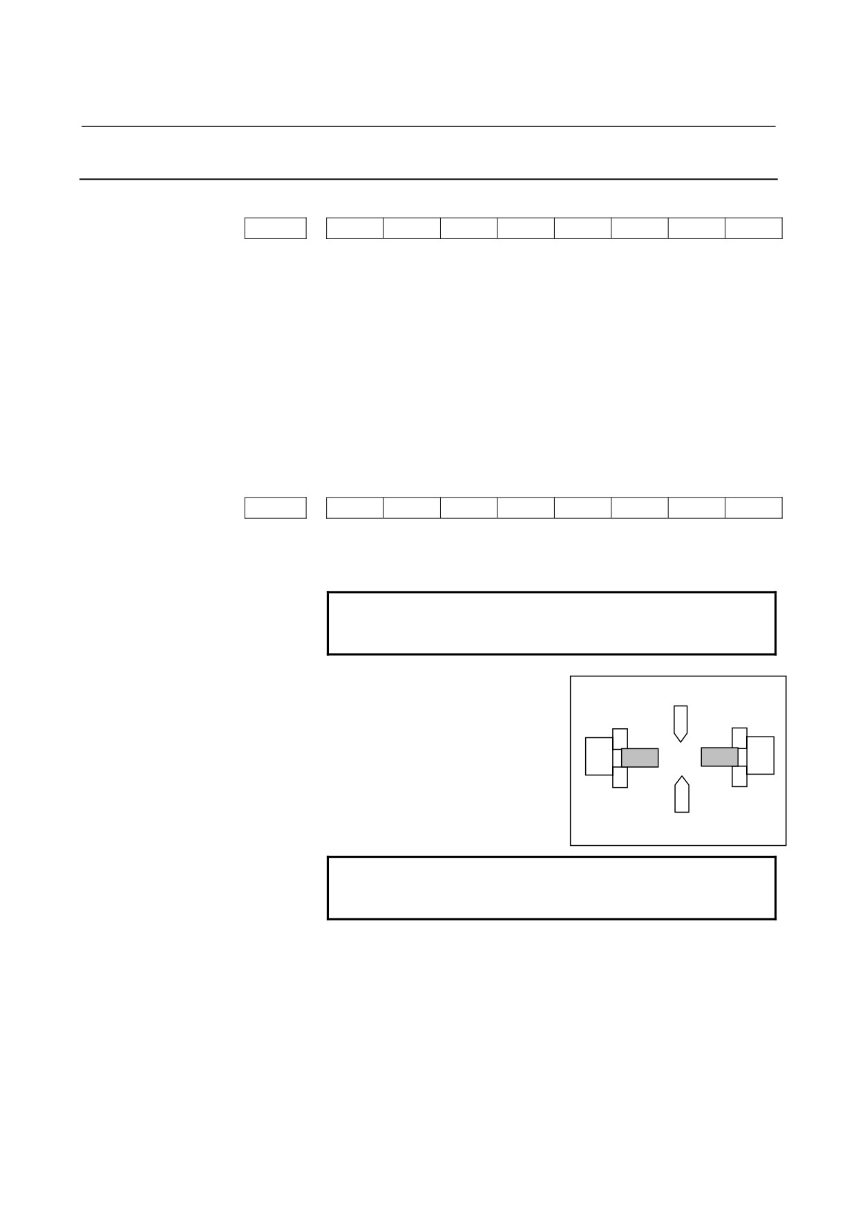
FMP 0 :
Tool post 1 is placed above spindle 1.
1 :
Tool post 1 is placed under spindle 1.
1
2
FSP 0 :
Tool post 1 is placed above spindle 2.
1 :
Tool post 1 is placed under spindle 2.
FMP=1, FSP=1
NOTE
FSP is available in the case of No.14702 SUB(#1)
= 1 and No.14701 FSE(#1) = 1 only.
CLP1= 0, CLP2 = 0 :
The size of the clipboard is set to 1024 bytes.
CLP1= 1, CLP2 = 0 :
The size of the clipboard is set to 2048 bytes.
CLP1= 0, CLP2 = 1 :
The size of the clipboard is set to 4096 bytes.
CLP1= 1, CLP 2 = 1 :
The size of the clipboard is set to 8192 bytes.
PCK 0 :
Process List Editing Function : The soft-key [ADD /] and [DEL /] for
program check function for each spindle are not displayed.
1 :
Process List Editing Function : The soft-key [ADD /] and [DEL /] for
program check function for each spindle are displayed.
- 748 -
B-63874EN/05
APPENDIX
A.PARAMETERS
#7
#6
#5
#4
#3
#2
#1
#0
14702
SFA
SFB
SFC
SFD
SUB
MT1
MT1
0 :
Vertical.
1 :
Horizontal (chuck located on the left side).
SUB
0 :
No sub-spindle is provided.
1 :
A sub-spindle is provided.
SFD
0 :
Normal rotation
is
assumed
if
G266#5
(SFRD)=0
and
G266#4
(SRVD)=1
Reverse rotation
is
assumed
if
G266#5
(SFRD)=1
and
G266#4
(SRVD)=0
1 :
Normal rotation
is
assumed
if
G266#5
(SFRD)=1
and
G266#4
(SRVD)=0
Reverse rotation
is
assumed
if
G266#5
(SFRD)=0
and
G266#4
(SRVD)=1
SFC
0 :
Normal rotation
is
assumed
if
G204#5
(SFRC)=0
and
G204#4
(SRVC)=1
Reverse rotation
is
assumed
if
G204#5
(SFRC)=1
and
G204#4
(SRVC)=0
1 :
Normal rotation
is
assumed
if
G204#5
(SFRC)=1
and
G204#4
(SRVC)=0
Reverse rotation
is
assumed
if
G204#5
(SFRC)=0
and
G204#4
(SRVC)=1
SFB
0 :
Normal rotation
is
assumed
if
G074#5
(SFRB)=0
and
G074#4
(SRVB)=1
Reverse rotation
is
assumed
if
G074#5
(SFRB)=1
and
G074#4
(SRVB)=0
1 :
Normal rotation
is
assumed
if
G074#5
(SFRB)=1
and
G074#4
(SRVB)=0
Reverse rotation
is
assumed
if
G074#5
(SFRB)=0
and
G074#4
(SRVB)=1
SFA
0 :
Normal rotation
is
assumed
if
G070#5
(SFRA)=0
and
G070#4
(SRVA)=1
Reverse rotation
is
assumed
if
G070#5
(SFRA)=1
and
G070#4
(SRVA)=0
1 :
Normal rotation
is
assumed
if
G070#5
(SFRA)=1
and
G070#4
(SRVA)=0
Reverse rotation
is
assumed
if
G070#5
(SFRA)=0
and
G070#4
(SRVA)=1
- 749 -

A.PARAMETERS
APPENDIX
B-63874EN/05
#7
#6
#5
#4
#3
#2
#1
#0
14703
G62
NCC
TAB
LST
GDM
SFN
FDS
FDS
0 :
During feed per revolution, actual feedrate is displayed as that of feed
per minute on the base screen.
1 :
During feed per revolution, actual feedrate is displayed as that of feed
per revolution on the base screen. (Refer to “3. All in one screen”.)
SFN
0 :
In lower part of the soft keys, shortcut numbers are not displayed.
1 :
In lower part of the soft keys, shortcut numbers are displayed.
GDM
0 :
When the CNC is a CNC for complex machining, just one guidance
message is displayed according to the T or M mode.
1 :
When the CNC is a CNC for complex machining, guidance messages
for the T and M modes are both displayed regardless of the mode set.
(Refer to “3. All in one screen”.)
LST
0 :
The soft-key [EDTCEL] is not displayed.
1 :
The soft-key [EDTCEL] is displayed.
TAB
0 :
On the multiple-tab screen, the cursor does not automatically move to
the next tab when [INPUT] is pressed in the lowermost edit box.
1 :
On the multiple-tab screen, the cursor automatically moves to the next
tab when [INPUT] is pressed in the lowermost edit box.
NCC
0 :
In NC statement conversion,
4-digit G code cycle machining
commands before expansion are output as comments.
1 :
In NC statement conversion,
4-digit G code cycle machining
commands before expansion are not output as comments.
G62
0 :
The capability of allowing the G62.4 signal to make the screen display
visible or invisible is disabled.
1 :
The capability of allowing the G62.4 signal to make the screen display
visible or invisible is enabled.
#7
#6
#5
#4
#3
#2
#1
#0
14704
DXC
DZX
DXY
IJK
LDM
SLM
PWO
PTO
PTO
0 :
During operation, data entry is prohibited on the tool offset setting
screen.
1 :
During operation, data entry is not prohibited on the tool offset setting
screen.
PWO
0 :
During operation, data entry is prohibited on the workpiece origin
offset setting screen.
1 :
During operation, data entry is not prohibited on the workpiece origin
offset setting screen.
SLM
0 :
The spindle load meter is displayed.
1 :
The spindle load meter is not displayed.
LDM
0 :
The servo load meter is displayed.
1 :
The servo load meter is not displayed.
IJK
0 :
The arc command in a contour program is output in IJK format.
1 :
The arc command in a contour program is output in R format.
Remark) contour program : Refer to “Entering Contour Programs”.
- 750 -
B-63874EN/05
APPENDIX
A.PARAMETERS
DXY
0 : The X coordinate in the XY plane contour program is output as a
radius value.
1 : The X coordinate in the XY plane contour program is output as a
diameter value.
DZX
0 : The X coordinate in the ZX plane contour program is output as a
radius value.
1 : The X coordinate in the ZX plane contour program is output as a
diameter value.
DXC
0 : The X coordinate in the XC plane contour program is output as a
radius value.
1 : The X coordinate in the XC plane contour program is output as a
diameter value.
NOTE
When Diameter programming is used in the lathe,
please be sure to set DXY, DZX and DXC to 1.
(The above case is the parameter No.1006
#3(DIA) = 1.)
- 751 -
A.PARAMETERS
APPENDIX
B-63874EN/05
A.2.3
Parameters for the Axial Configuration of the Machine
These parameters set the axial configuration of the machine. (Used in
machining simulation.)
14706
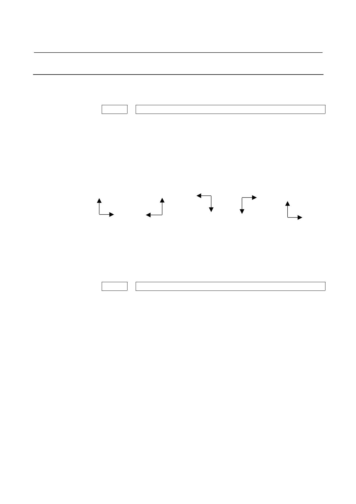
DRCTS1
(FANUC standard settings = 20 or 16)
DRCTS 1 :
Number of Workpiece coordinate for main spindle
16
:
Right-handed coordinate system, right = +Z, up = +X
17
:
Right-handed coordinate system, right = -Z, up = +X
18
:
Right-handed coordinate system, right = -Z, up = -X
19
:
Right-handed coordinate system, right = +Z, up = -X
20
:
Right-handed coordinate system, right = +X, up = +Z
X
X
Z
Z
Z
Z
Z
X
X
X
16
17
18
19
20
FANUC standard settings = 20 :
Vertical machining center/vertical lathe
FANUC standard settings = 16 :
Horizontal machining center/horizontal lathe
14707
DRCTS2
(FANUC standard settings = 0 : Not use)
DRCTS 2 :
Number of Workpiece coordinate for sub spindle if existing
16
:
Right-handed coordinate system, right = +Z, up = +X
17
:
Right-handed coordinate system, right = -Z, up = +X
18
:
Right-handed coordinate system, right = -Z, up = -X
19
:
Right-handed coordinate system, right = +Z, up = -X
20
:
Right-handed coordinate system, right = +X, up = +Z
- 752 -

B-63874EN/05
APPENDIX
A.PARAMETERS
A.2.4
Settings for Spindle Status Display
These parameters set spindle status display on the base screen.
14710
AST
(FANUC standard settings = 0)
AST
0 : When a CNC unit for complex machining is used, actual spindle
speed/spindle load ratio/spindle status display on the base screen is not
automatically switched in turning mode.
≠0 : Spindle number: When a CNC unit for complex machining is used,
actual spindle speed/spindle load ratio/spindle status display on the
base screen is automatically switched to the display for a specified
spindle number in turning mode.
14711
ASM
(FANUC standard settings = 0)
ASM
0 : When a CNC unit for complex machining is used, actual spindle
speed/spindle load ratio/spindle status display on the base screen is not
automatically switched in milling mode.
≠0 : Spindle number: When a CNC unit for complex machining is used,
actual spindle speed/spindle load ratio/spindle status display on the
base screen is automatically switched to the display for a specified
spindle number in milling mode.
A.2.5 Setting for the Display Language
This parameter sets the display language on the Manual Guide i
screen.
14712
MSGLANG
(FANUC standard settings = 0)
MSGLANG
0 : The setting of language which NC displays is assumed. But if it is not
any other than English, Japanese, German, French, Italian, Spanish,
Swedish, Czech, Portuguese or Polish, MANUAL GUIDE i is
displayed in English.
1 : English
2 : Japanese
3 : German
4 : French
5 : Italian
6 : Spanish
7 : Swedish
8 : Czech
9 : Portuguese
10 : Polish
except above : English
- 753 -

A.PARAMETERS
APPENDIX
B-63874EN/05
NOTE
Language file 1 is necessary to display Japanese,
Germany, French or Italian.
And language file 2 is necessary to display Spanish,
Czech, Portuguese or Polish.
A.2.6
Settings for Graphic Display
These parameters set graphic display.
14713
GRPSCALE
(FANUC standard settings = 0)
GRPSCALE : Scaling unit for graphic enlargement and reduction.
Scaling unit = 64/GRPSCALE
(Valid data range:
0 to 255. If 0 is set, 64 is assumed.)
14714
GRPMOVEH
(FANUC standard settings = 0)
GRPMOVEH : Graphic horizontal movement unit (dots)
(Valid data range:
0 to 255. If 0 is set, 64 dots is assumed.)
14715
GRPMOVEV
(FANUC standard settings = 0)
GRPMOVEV : Graphic vertical movement unit (dots)
(Valid data range:
0 to 255. If 0 is set, 35 dots is assumed.)
14716
GRPROTA
(FANUC standard settings = 0)
GRPROTA : Graphic rotation direction movement unit (angle)
(Valid data range:
0 to 255. If 0 is set, 10 degrees is assumed.)
- 754 -

B-63874EN/05
APPENDIX
A.PARAMETERS
A.2.7
Settings for Machining Simulation Axes
These parameters set machining simulation.
14717
SMLCNO
(FANUC standard settings = 0)
SMLCNO :
Rotate (Cs) axis number
Valid data range: from 0 to the number of controlled axes
NOTE
1 In case of one Cs axis of main spindle, please be
sure to set No.14717 only. If no Cs axis or
Animation option, it is unnecessary to set.
2 In case of two Cs axis with main and sub spindle,
please be sure to set No.27301, No.27302 and
No.27312 #0. And No.14717 is used as working
number for Cs axis, as follows.
3 When 27312#0 = 1, No. 14717 is rewritten to the
value of No.27301 or No.27302 by a spindle
selection command (G1998). Therefore, in the
case of No.27312 #0=1, please be sure to specify
Spindle selection command (G1998) before Milling
cycles.
4 As to Apindle selection command (G1998), please
refer to “9.5 Setting of data for Animation”.
14718
SMLRTNO
(FANUC standard settings = 0)
SMLRTNO :
Rotate (Cs) axis number, which tilts tool head or table
Valid data range: from 0 to the number of controlled axes
NOTE
No.14718 is used in Simulation or Turning cycles.
Therfore, if the machine has a rotate axis which
tilts tool head or table, please sure to set this
parameter.
If no such axis or animation option, it is not
necessary to set.
- 755 -

A.PARAMETERS
APPENDIX
B-63874EN/05
A.2.8 Settings for Subprogram Selection Screens
These parameters set the registration start/end numbers of subprogram
selection screens.
14720
TFIGSNO
(FANUC standard settings = 0)
TFIGSNO : Registration start number of the turning subprogram selection screen.
14721
TFIGENO
(FANUC standard settings = 0)
TFIGENO : Registration end number of the turning subprogram selection screen.
14722
MFIGSNO
(FANUC standard settings = 0)
MFIGSNO : Registration start number of the milling subprogram selection screen.
14723
MFIGENO
(FANUC standard settings = 0)
MFIGENO : Registration end number of the milling subprogram selection screen.
- 756 -
B-63874EN/05
APPENDIX
A.PARAMETERS
A.2.9
Settings for the Color Palette for Screen Display
These parameters set the colors used to display screen components.
Color setting data for a screen display color number* (1 to 16)
•
Specify color setting data with a 6-digit number in the format of
“xxyyzz”.
(xx:Value for red, yy:Value for green, zz:Value for blue)
•
The valid data range of each color value is 0 to 63. A value
greater than 63 is interpreted as 63.
•
For a number with less than six digits, all the unspecified digits
are interpreted as high-order ones and are all assumed 0.
14724
DSPCOL1
DSPCOL1 :
Color of the cursor in the program display section on the base screen.
14725
DSPCOL2
DSPCOL2 :
Used to display alarms in the system title display section.
14726
DSPCOL3
DSPCOL3 :
Used to display the mode and line number in the system title display
section.
14727
DSPCOL4
DSPCOL4 :
Used to display the background of the alarm indication and the load
meter.
14728
DSPCOL5
DSPCOL5 :
Used to display the background of the title in the status display section,
soft key characters, item name characters, and the scroll box of the
scroll bar.
14729
DSPCOL6
DSPCOL6 :
Used to display the serial numbers of selection screens.
14730
DSPCOL7
DSPCOL7 :
Used to display the background of the system title display section.
14731
DSPCOL8
DSPCOL8 :
Used to display characters in the title section.
- 757 -

A.PARAMETERS
APPENDIX
B-63874EN/05
14732
DSPCOL9
DSPCOL9 :
Used to display the mode on the base screen and the material elements
of arbitrary figures.
14733
DSPCOL10
DSPCOL10 :
Used to display frames.
14734
DSPCOL11
DSPCOL11 :
Used to display cells that cannot be edited by the process list edit
function.
14735
DSPCOL12
DSPCOL12 :
Used to display the background of the status display section.
14736
DSPCOL13
DSPCOL13 :
Used to display the bar of the load meter.
14737
DSPCOL14
DSPCOL14 :
Used to display the background of the cursor mode.
14738
DSPCOL15
DSPCOL15 :
Used to display window shadows.
14739
DSPCOL16
DSPCOL16 :
Used to display the background of the base screen.
If these parameters are set to 0, the following values are used as their
respective initial values.
No.14724 = 636300 Yellow
No.14725 = 630000 Red
No.14726 = 003200 Green
No.14727 = 636300 Yellow
No.14728 = 000063 Blue
No.14729 = 420042 Purple (pinkish)
No.14730 = 323260 Light ultramarine
No.14731 = 636363 White
No.14732 = 163616 Bright green
No.14733 = 000000 Black
No.14734 = 121212 Very dark gray
No.14735 = 484848 Bright gray
No.14736 = 006363 Bright, light blue
No.14737 = 20203C Light ultramarine
No.14738 = 242424 Dark gray
No.14739 = 404040 Rather bright gray
- 758 -

B-63874EN/05
APPENDIX
A.PARAMETERS
A.2.10
Settings for the Color Palette for Icon Display
These parameters set the color palette colors used to display icons.
Color setting data for an ICOCOL* screen display color number* (1
to 16)
•
Specify color setting data with a 6-digit number in the format of
“xxyyzz”.
(xx:Value for red, yy:Value for green, zz:Value for blue)
•
The valid data range of each color value is 0 to 63. A value
greater than 63 is interpreted as 63.
•
For a number with less than six digits, all the unspecified digits
are interpreted as high-order ones and are all assumed 0.
14740
ICOCOL1
14741
ICOCOL2
14742
ICOCOL3
14743
ICOCOL4
14744
ICOCOL5
14745
ICOCOL6
14746
ICOCOL7
14747
ICOCOL8
14748
ICOCOL9
14749
ICOCOL10
14750
ICOCOL11
14751
ICOCOL12
14752
ICOCOL13
14753
ICOCOL14
14754
ICOCOL15
14755
ICOCOL16
- 759 -
A.PARAMETERS
APPENDIX
B-63874EN/05
If these parameters are set to 0, the following values are used as their
respective initial values.
No.14740 = 630000
Red
No.14741 = 003200
Green
No.14742 = 636300
Yellow
No.14743 = 000063
Blue
No.14744 = 420042
Purple
No.14745 = 480040
Dark pink
No.14746 = 636363
White
No.14747 = 163616
Bright green
No.14748 = 000000
Black
No.14749 = 006060
Bright, light blue
No.14750 = 484848
Bright gray
No.14751 = 006363
Bright blue
No.14752 = 320000
Dark red
No.14753 = 242424
Dark gray
No.14754 = 404040
Rather bright gray
No.14755 = 000000
Black
- 760 -

B-63874EN/05
APPENDIX
A.PARAMETERS
A.2.11
Settings for the Color Palette for Guide Display
These parameters set the colors used to display guides.
Color setting data for a GIDCOL* screen display color* (1 to 16)
•
Specify color setting data with a 6-digit number in the format of
“xxyyzz”.
(xx:Value for red, yy:Value for green, zz:Value for blue)
•
The valid data range of each color value is 0 to 63. A value
greater than 63 is interpreted as 63.
•
For a number with less than six digits, all the unspecified digits
are interpreted as high-order ones and are all assumed 0.
14756
GIDCOL1
GIDCOL 1 :
Material color.
14757
GIDCOL2
GIDCOL2 :
Material frame color.
14758
GIDCOL3
GIDCOL3 :
Tool color.
14759
GIDCOL4
GIDCOL4 :
Tool frame color.
14760
GIDCOL5
GIDCOL5 :
Tool path (cutting feed).
14761
GIDCOL6
GIDCOL6 :
Tool path (rapid traverse).
14762
GIDCOL7
GIDCOL7 :
Dimensional line.
14763
GIDCOL8
GIDCOL8 :
Character color (unselected character).
14764
GIDCOL9
GIDCOL9 :
Character color (selected character).
- 761 -