FANUC MANUAL GUIDE i. OPERATOR’S MANUAL - page 24
6.MODAL DISPLAY OF OFFSET TYPES TOOL MANAGEMENT
B-63874EN/05
6
MODAL DISPLAY OF OFFSET TYPES
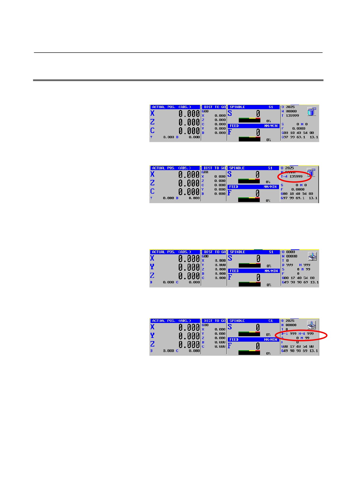
Two tool offset number specification methods are available: the
conventional method in which a offset number independent of a tool
number is directly specified, and the method in which a offset type
associated with a tool number is specified. With the latter, when a
offset type is specified, the offset type is displayed at the modal
information display position as long as the offset type remains
effective.
- 672 -
B-63874EN/05
TOOL MANAGEMENT 6.MODAL DISPLAY OF OFFSET TYPES
6.1
SCREEN DISPLAY ITEMS
•
Screen that appears when a offset number is directly specified
(on the lathe)
This screen is the same as the conventional one.
•
Screen that appears when a offset type is specified (on the lathe)
If bit 7 (STS) of parameter No. 14823 is 1 and the offset type is
displayed, the offset type is displayed after 'T-' in the status
display section.
•
Screen that appears when a offset number is directly specified
(on the milling machine)
This screen is the same as the conventional one.
•
Screen that appears when a offset type is specified
(on the
milling machine)
If bit 7 (STS) of parameter No. 14823 is 1 and the offset type is
displayed, the offset type is displayed after 'D-' and 'H-' in the
status display section.
- 673 -
6.MODAL DISPLAY OF OFFSET TYPES TOOL MANAGEMENT
B-63874EN/05
6.2
DISPLAYED OFFSET TYPES (SET BY THE MACHINE
TOOL BUILDER)
In the status display section, offset types are displayed by referencing
the following variables:
#90248, D code offset type on the milling machine
#90249, offset type on the lathe and H code offset type on the milling
machine
When specifying a tool offset number, the machine tool builder is
required to set a offset type in variables #90248 and #90249 in the
called macro program, using T, D, and H codes.
If directly specifying a offset number, instead of specifying a offset
type, the machine tool builder is required to set the above variables to
null.
- 674 -
B-63874EN/05
TOOL MANAGEMENT 7.DISPLAY TOOL MANAGEMENT DATA OF CNC STANDARD SCREEN
7
DISPLAY TOOL MANAGEMENT DATA
OF CNC STANDARD SCREEN
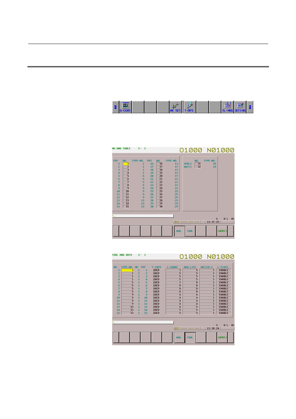
By pressing the soft key displayed on the MANUAL GUIDE i screen,
it is possible to change the screen to the tool management data table
on the NC side.
In order to use this feature, it is necessary to set the
TLD(No.14823#6).
- 675 -
7.DISPLAY TOOL MANAGEMENT DATA OF CNC STANDARD SCREEN TOOL MANAGEMENT
B-63874EN/05
7.1
OPERATION
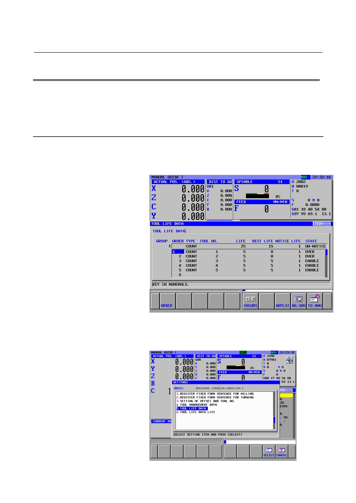
<1> At the case of the parameter TLD(No.14823#6) setting '1' ,the
following [TL-MNG] is displayed on the base screen in the each
mode.
(Example) EDIT mode
<2> Pressing [TL-MNG] displays the following tool management
data screen.
(Magazine management table screen)
(Tool management data table screen)
- 676 -
B-63874EN/05
TOOL MANAGEMENT 7.DISPLAY TOOL MANAGEMENT DATA OF CNC STANDARD SCREEN
NOTE
Either “Magazine management table screen” or “Tool
management data table screen” is displayed. The
screen previously displayed is appeared.
<3> On this screen, if the function keys for startup MANUAL
GUIDE i are pressed, the screen returns to the MANUAL
GUIDE i base screen.
- 677 -
8.OTHERS
TOOL MANAGEMENT
B-63874EN/05
8
OTHERS
- 678 -
B-63874EN/05
TOOL MANAGEMENT
8.OTHERS
8.1
RETURN TO MENU SCREEN
It is possible to return to the menu screen from tool management
screen. And it is possible to return to the base screen as before by
parameter setting.
8.1.1
Return to SETTINGS Menu Screen
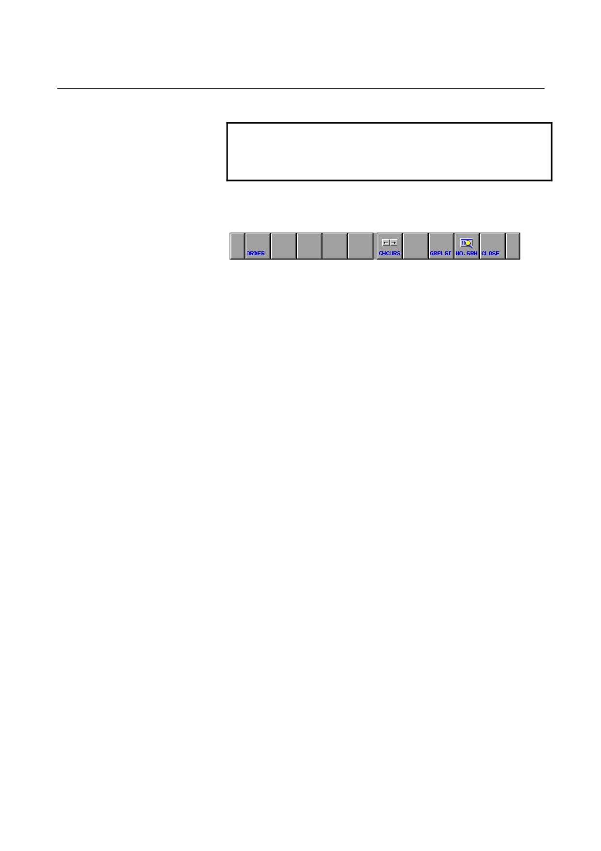
<1> Press [SETTING]
<2> From “BASIC” menu screen, select “TOOL LIFE DATA”,and
the following screen appears.
<3> Pressing [TO MNU] displays the following menu screen. The
cursor is displayed on the position of previous selected screen
(in this case “TOOL LIFE DATA”)
- 679 -
8.OTHERS
TOOL MANAGEMENT
B-63874EN/05
NOTE
“SETTING OF OFFSET AND TOOL NO.”,”TOOL
MANAGEMENT DATA”, and “TOOL LIFE DATA
LIST” are the same as "TOOL LIFE DATA"
When the parameter No. 14850#2 is ‘1’, [CLOSE] is displayed instead
of [TO MNU]. Pressing [CLOSE] returns to the base screen as before.
- 680 -

B-63874EN/05
TOOL MANAGEMENT
8.OTHERS
8.2
INHIBITION OF EDITING TOOL MANAGEMENT DATA AT
CNC STANDARD SCREEN
On the tool management data screen of NC side, it is possible to
inhabit to edit the tool management data.
8.2.1
Operations
In the case of the parameter No.14851#7 on, when [EDIT] is pressed
on the tool management data screen, the following waning is
displayed. And the tool management data cannot be altered at NC
screen.
“WRITE PROTECTED”
8.3
USING TOOL MANAGEMENT DATA
The following customization data on the tool management data table
are used by the tool management functions for MANUAL GUIDE i.
Therefore MTB can not use these customization items when the tool
management functions for MANUAL GUIDE i is used.
Item
Bit
Content
Customization item 0
7
Previous Notice Flag
6
5
4
3
2
1
0
Customization item 1
TOOL NO.
Customization item 2
OFFSET NO.
Customization item 3
TOOL KIND
Customization item 4
TOOL USING ORDER
NOTE
In order to enable “Tool Using Order”, it is
necessary to set the parameter No. 13203#6 to 1
and No.13260 to 4. When these parameter are 0,
the shortest life tool is searched not according to
this order.
- 681 -
VI. EXAMPLE OF PROGRAMMING
OPERATION

B-63874EN/05
EXAMPLE OF PROGRAMMING
1.EXPLANATORY NOTES
1
EXPLANATORY NOTES
WARNING
All data described in this Part such as parameter,
offset data and part program cannot be used for
actual machining. Actual data varies from one
machine model to another. Refer to the applicable
manual supplied by the respective machine tool
builders for details.
If the set data does not match the characteristic of a
specific machine, the tool may bump against the
workpiece, and the machine may be forced to
perform unnatural machining, possibly causing
damage to the tool and/or machine, and even
injuries.
The part program made by using MANUAL GUIDE i has a form of
ISO-code program with G-code and so on.
You must enter the program used for such as tool changing, tool offset,
spindle rotation, approaching and releasing in the form of ISO-code
program.
In addition to those actions, you can enter the part program for
complicated machining motions, which are usually difficult to make
by ISO-code form, as a
“Cycle machining” by using menu
programming method. This cycle machining is made in form of a
block including G-4digits and necessary data items.
In the following explanations, the contents of a square frame mean the
actual operations, and each operation are described as follows.
[NEWPRG]
: Push a soft-key
12345
: Enter numeric data
INPUT
: Push an INPUT key
↓ ↑ → ←
: Push a CURSOR key
⇓ ⇑
: Push a PAGE key
(CREATE NEW PROG)
: Name of Window or Data item
<START>
: Name of Tab
<<1.CYLINDER>>
: Menu item
- 685 -
2.LATHE
EXAMPLE OF PROGRAMMING
B-63874EN/05
2
LATHE
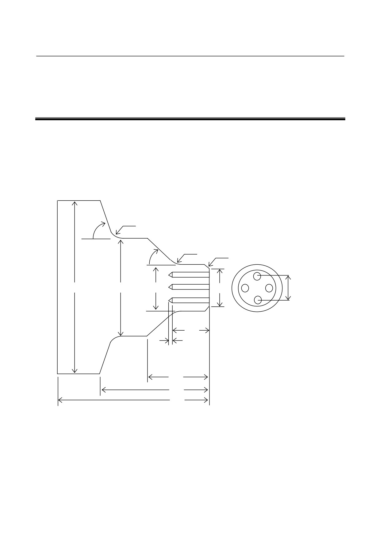
Example) Outer Roughing/Finishing, C-axis drilling
Workpiece
: Round bar (φ100×80)
1st Process
: Outer roughing by General purpose tool
for roughing (T0101)
2nd Process
: Outer finishing by General purpose tool
for finishing (T0202)
3rd Process
: C-axis end face drilling by Drill (T0303)
R3
80°
R3
C2
60°
φ100
φ60
φ35
φ31
φ22
20
2
30
50
80
- 686 -
B-63874EN/05
EXAMPLE OF PROGRAMMING
2.LATHE
2.1
SETTING TOOL OFFSET DATA
WARNING
1
Operation of tool offset setting varies from one
machine model to another. So operations described
in this section may differ from those ion actual
machine.
As to the actual operation of tool offset setting on
the actual machine, refer to the applicable manual
supplied by the respective machine tool builders for
details.
If the set data does not match the characteristic of a
specific machine, the tool may bump against the
workpiece, and the machine may be forced to
perform unnatural machining, possibly causing
damage to the tool and/or machine, and even
injuries.
2
As to the operations on a machine described in this
chapter, refer to the applicable manual supplied by
the respective machine tool builders for details.
If the operation does not match the characteristic of
a specific machine, the tool may bump against the
workpiece, and the machine may be forced to
perform unnatural machining, possibly causing
damage to the tool and/or machine, and even
injuries.
- 687 -
2.LATHE
EXAMPLE OF PROGRAMMING
B-63874EN/05
2.1.1
Setting of Z-axis Offset Data
(1) Set a standard workpiece on a chuck of lathe. After then, for
safety, take measure to keep fully safety such as closing the
machine door.
(2) Execute the machine reference position return of X-and Z-axis.
(3) Output T-code in MDI mode, and select the tool for measuring.
(4) Make a spindle rotate by fully safety speed.
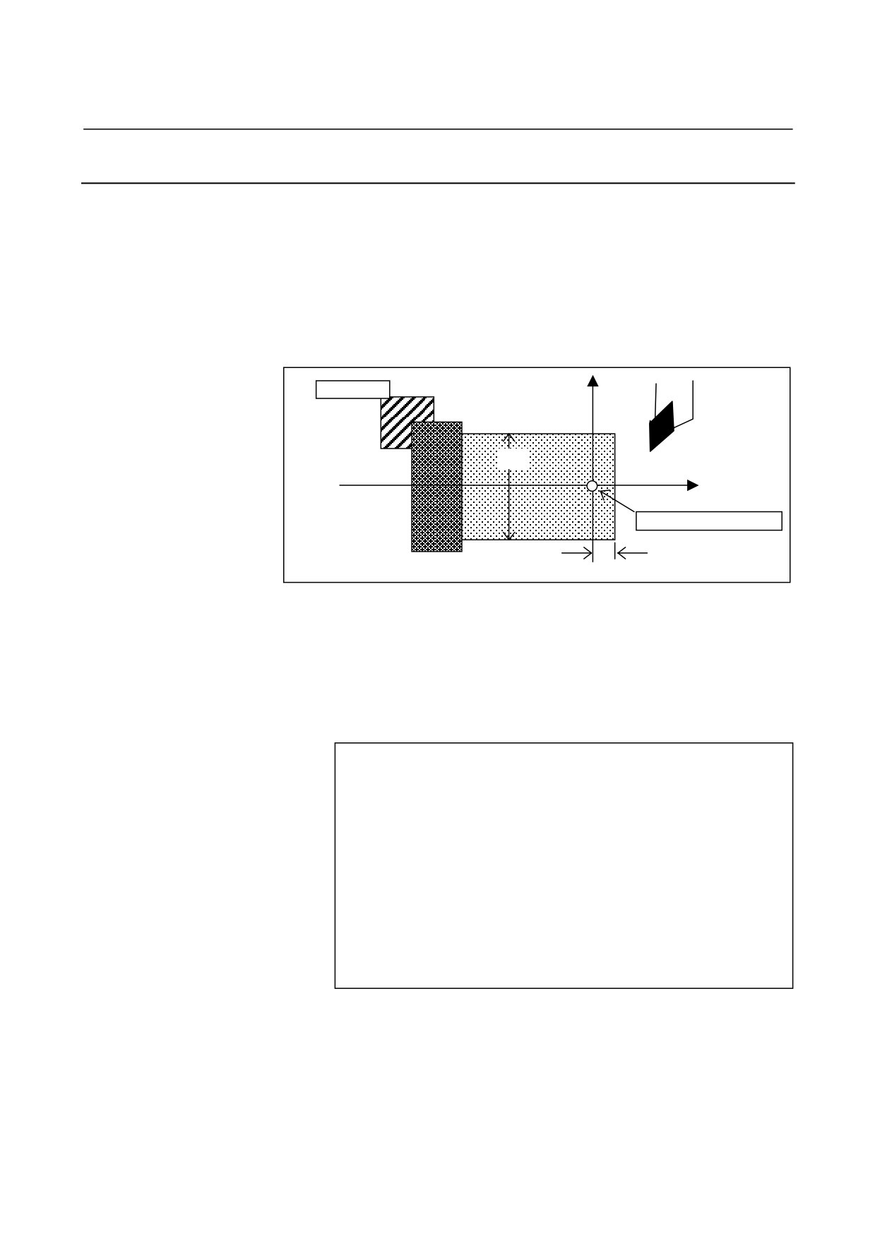
(5) Cut surface A of the following drawing in manual mode with a
actual tool.
+X
Chuck
Surface B
α
Surface A
+Z
Workpiece origin
β
(6) Release the tool in X-axis direction only, without moving Z-axis.
(7) Stop the spindle.
(8) Measure distance β from the zero point in the workpiece
coordinate system to surface A.
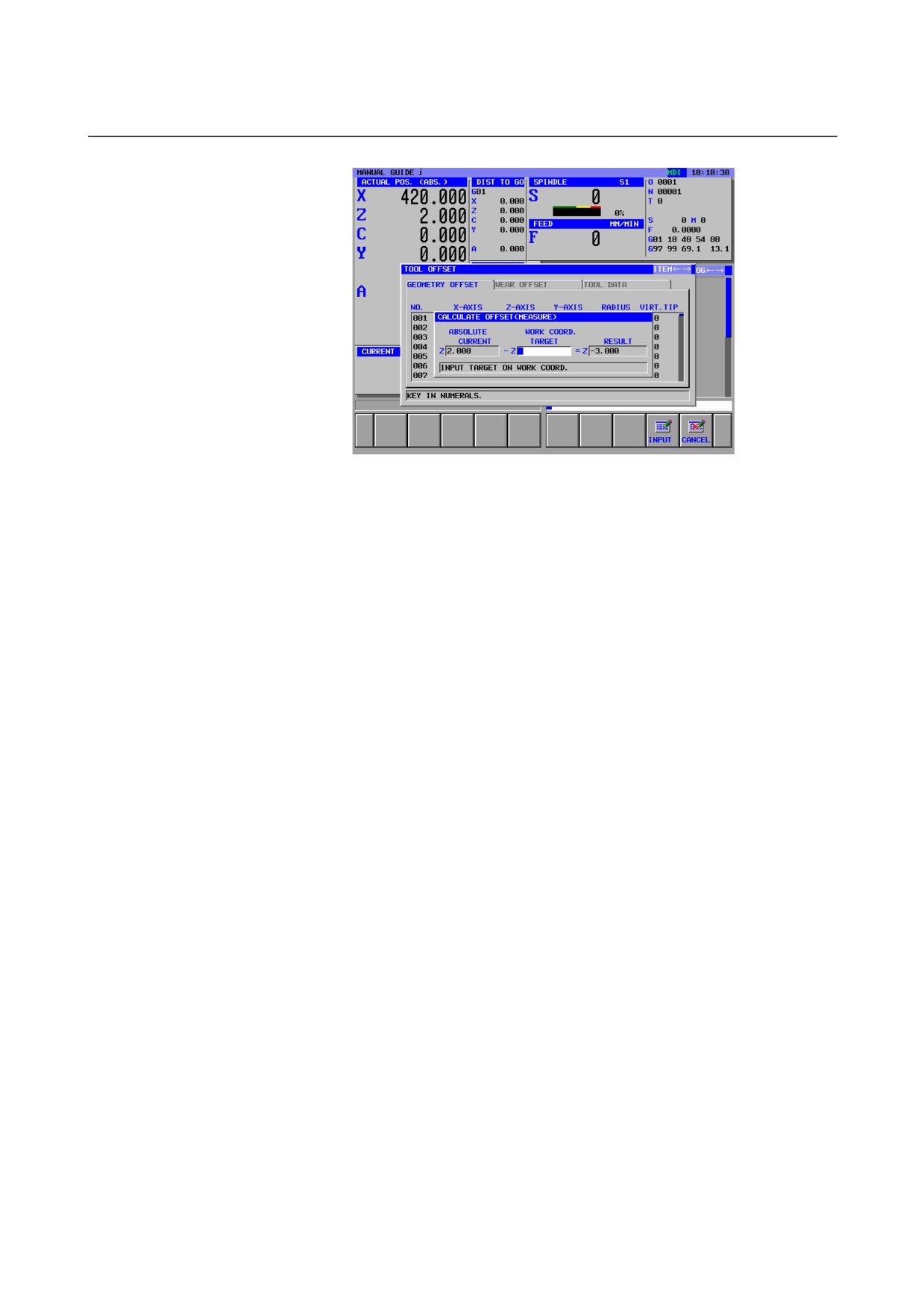
Operate as follows on the MANUAL GUIDE i screen.
[T-OFS]
(TOOL OFFSET)
<GEOMETRY OFFSET>
[CHCURS]
(ITEM <--> will be displayed on the right upper part of the window)
→
<<Z-AXIS>>
↓
<<Offset number for the used tool>>
[MEASUR]
(CALCULATE OFFSET(MEASURE))
β INPUT
(Z WORK COORD.TARGET)
Check the result of calculation displayed in the (RESULT)
[INPUT]
(GEOMTERY OFFSET)
- 688 -
B-63874EN/05
EXAMPLE OF PROGRAMMING
2.LATHE
- 689 -
2.LATHE
EXAMPLE OF PROGRAMMING
B-63874EN/05
2.1.2
Setting of X-axis Offset Data
Continuously after setting of Z-axis offset data, set the X-axis offset
data as follows.
(1) Make a spindle rotate by fully safety speed.
(2) Cut surface B of the following drawing in manual mode with a
actual tool.
(3) Release the tool in Z-axis direction only, without moving X-axis.
(4) Measure the diameter α of surface B. Set this value as the
measured value for X-axis in the desired offset No.
(TOOL OFFSET)
<GEOMETRY OFFSET>
(ITEM <--> will be displayed on the right upper part of the window)
←
<<X-AXIS>>
↓
<<Offset number for the used tool>>
[MEASUR]
(CALCULATE OFFSET(MEASURE))
α INPUT
(X WORK COORD.TARGET)
Check the result of calculation displayed in the (RESULT)
[INPUT]
(GEOMTERY OFFSET)
Repeat the above procedure of Z-axis and X-axis offset data
measurement operations for necessary tools.
NOTE
1 Always measure the axis of diameter specification
in terms of diameter value.
2 When the measured value is input as the geometry
offset value by [MEASUR], the corresponding wear
offset value is set 0.
3 Wear offset data is used for offsetting the error
measured on the machined product or worn down
amount of a tool.
- 690 -
B-63874EN/05
EXAMPLE OF PROGRAMMING
2.LATHE
2.2
SETTING OF WORKPIECE COORDINATE SYSTEM SHIFT
DATA
After setting the geometry offset data for necessary tools, set the
workpiece origin on the actual workpiece used for machining.
On the lathe, the rotating center line of a workpiece is usually set to
workpiece origin of X-axis. So, the workpiece origin of X-axis need
not be set again for new workpiece.
For Z-axis workpiece origin,, you must set again for new workpiece
when you change to new one.
In this section, operations for setting the workpiece end surface to the
workpiece origin are described.
(1) Set the actually machined workpiece on a chuck of lathe. After
then, for safety, take measure to keep fully safety such as closing
the machine door.
(2) Execute the machine reference position return of X-and Z-axis.
(3) Output T-code in MDI mode, and select the tool for measuring.
(4) Make a spindle rotate by fully safety speed.
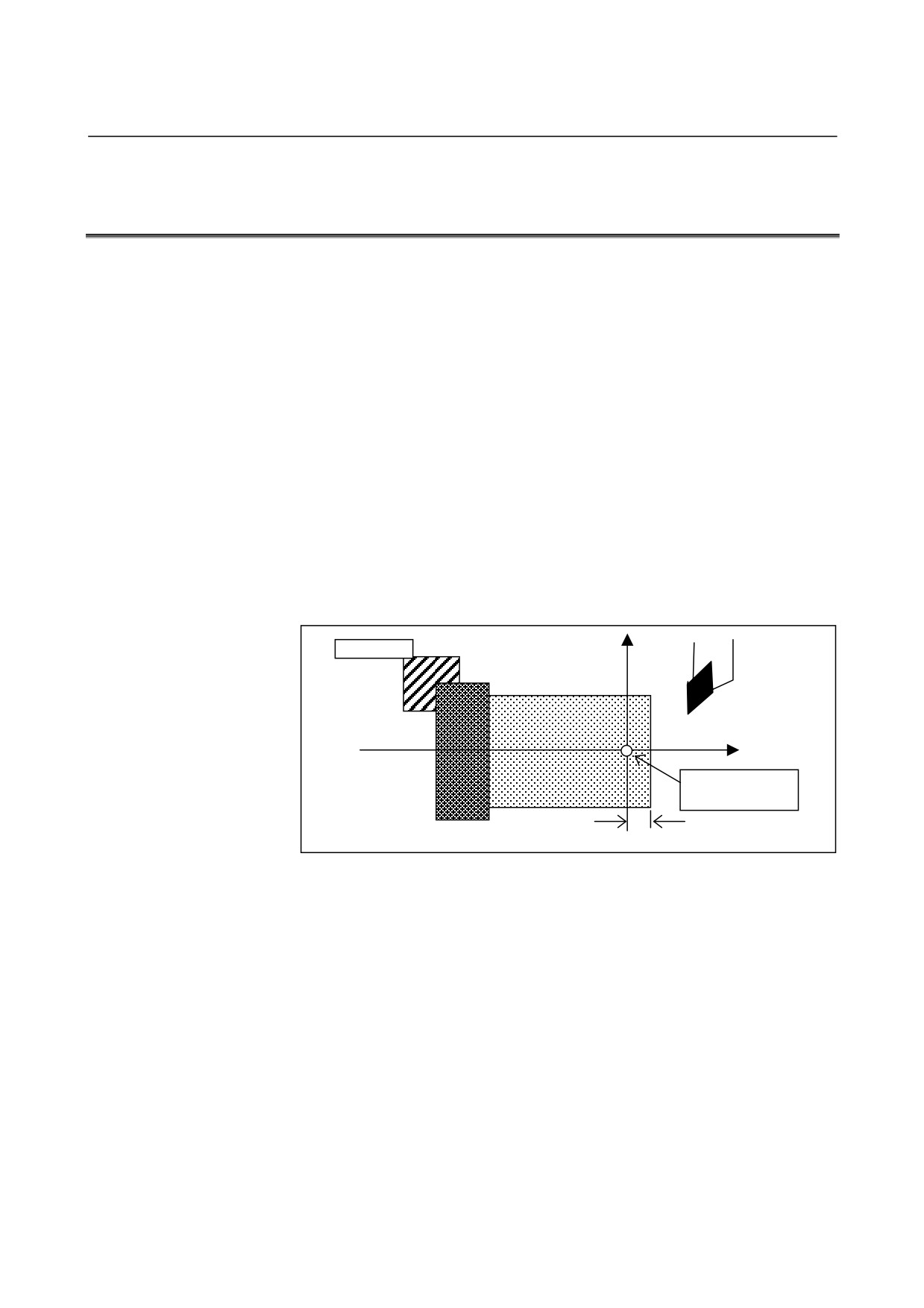
(5) Cut surface A of the following drawing in manual mode with a
actual tool.
+X
Chuck
Surface A
+Z
Workpiece origin
β
(6) Release the tool in X-axis direction only, without moving Z-axis.
(7) Stop the spindle.
(8) Define the end surface amount β.
- 691 -
2.LATHE
EXAMPLE OF PROGRAMMING
B-63874EN/05
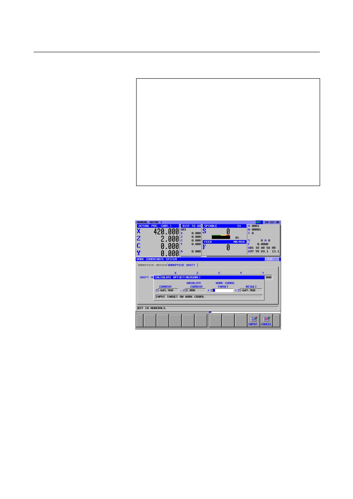
Operate as follows on the MANUAL GUIDE i screen.
[WK SET]
(WORK CORRDINATE SYSTEM)
<WORKPIECE ORIGIN>
(TAB <--> will be displayed on the right upper part of the window)
→
<WORKPIECE SHIFT>
[CHCURS]
(ITEM <--> will be displayed on the right upper part of the window)
→
<<Z>>
[MEASUR]
(CALCULATE OFFSET(MEASURE))
β INPUT
(WORK COORD.TARGET)
Check the result of calculation displayed in the (RESULT)
[INPUT]
(WORK COORDINATE SYSTEM)
As the result of the above operations, confirm that the absolute
coordinate of the Z-axis is changed to the value of entered β value.
- 692 -
B-63874EN/05
EXAMPLE OF PROGRAMMING
2.LATHE
2.3
PREPARING OF THE FIXED FORM SENTENCE MENU
As to the fixed form sentence, machine tool builder usually sets the
suitable menu for specified respective machine. But, you can enter his
own menu on the MANUAL GUIDE i screen by yourself.
2.3.1
Entering the Fixed Form Sentence for Turning Machining
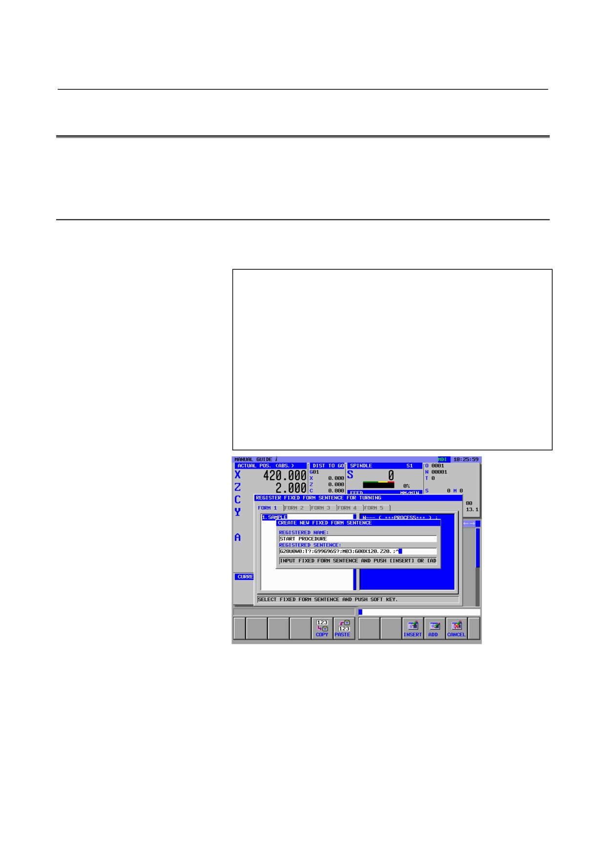
Enter the fixed form sentence menu which will be called by the
soft-key [FIXFRM] in the soft-key group for turning machining.
[SETTING]
(SETTING)
<BASIC>
↓
<<2.REGISTER FIXED FORM SENTENCE FOR TURNING>>
[SELECT]
(REGISTER FIXED FORM SENTENCE FOR TURNING)
<FORM1>
[NEW]
(CREATE NEW FIXED FORM SENTENCE)
<SENTENCE NAME : >
START PROCEDURE INPUT
<REGISTERED SENTENCE : >
G28 U0 W0 ; T? ; G99 G96 S? ; M03 ; G00 X120. Z20. ;
[INSERT]
[CLOSE]
- 693 -
2.LATHE
EXAMPLE OF PROGRAMMING
B-63874EN/05
2.3.2
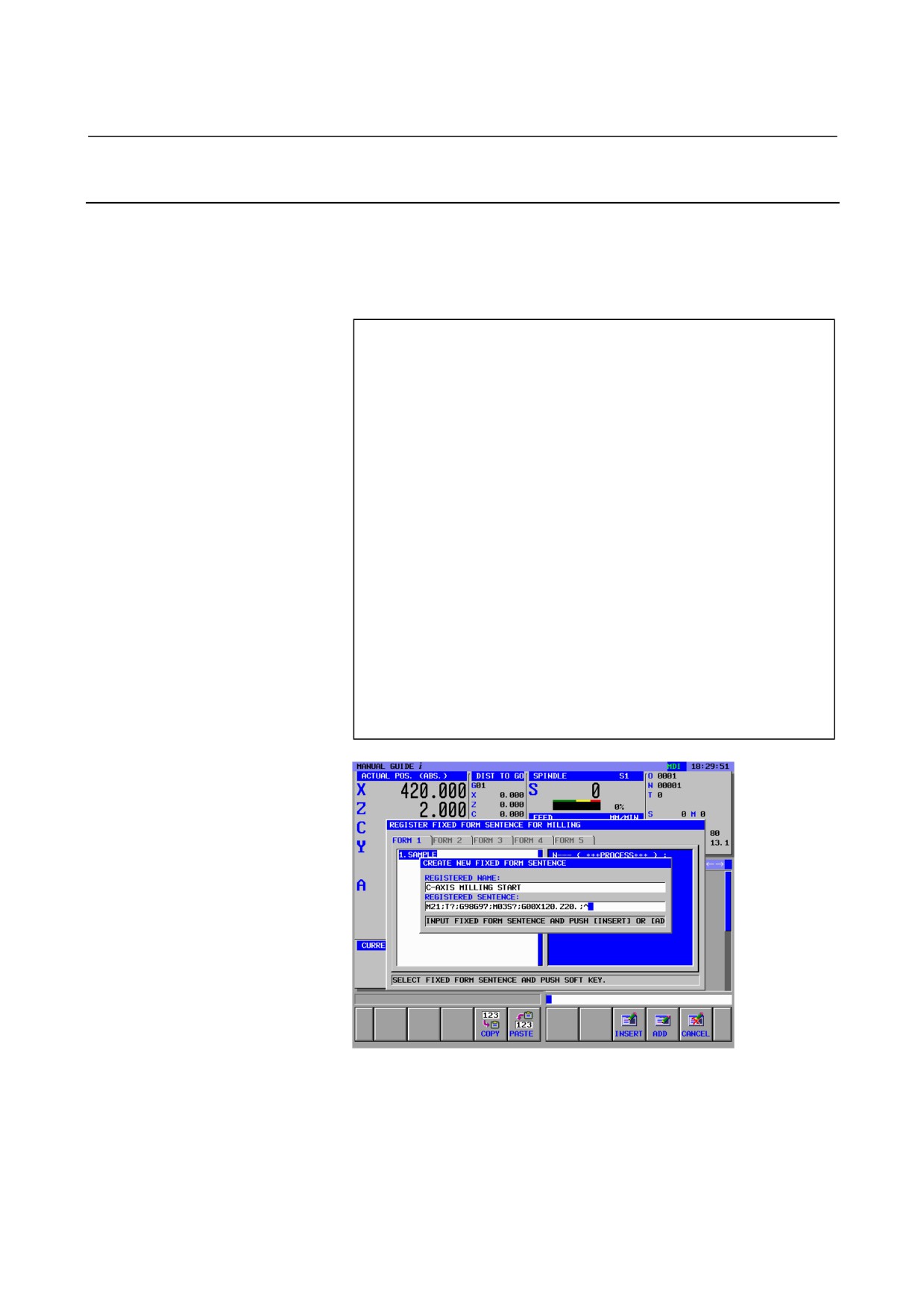
Entering of the Fixed Form Sentence for Milling Machining
Enter the fixed form sentence menu which will be called by the
soft-key [FIXFRM] in the soft-key group for milling machining.
Enter data for the program for milling starting procedure and program
end procedure.
[SETTING]
(SETTING)
<BASIC>
↓
<<1.REGISTER FIXED FORM SENTENCE FOR MILLING>>
[SELECT]
(REGISTER FIXED FORM SENTENCE FOR MILLING)
<FORM1>
[NEW]
(CREATE NEW FIXED FORM SENTENCE)
<SENTENCE NAME : >
C-AXIS MILLING START INPUT
<REGISTERED SENTENCE : >
M21. ; T? ; G98 G97 ; M03 S? ; G00 X120. Z20. ;
[INSERT]
→
<FORM5>
[NEW]
(CREATE NEW FIXED FORM SENTENCE)
<SENTENCE NAME : >
PROGRAM END INPUT
<REGISTERED SENTENCE : >
M05. ; G00 X200. ; G28 U0 W0 ; M02 ;
[INSERT]
[CLOSE]
- 694 -
B-63874EN/05
EXAMPLE OF PROGRAMMING
2.LATHE
2.4
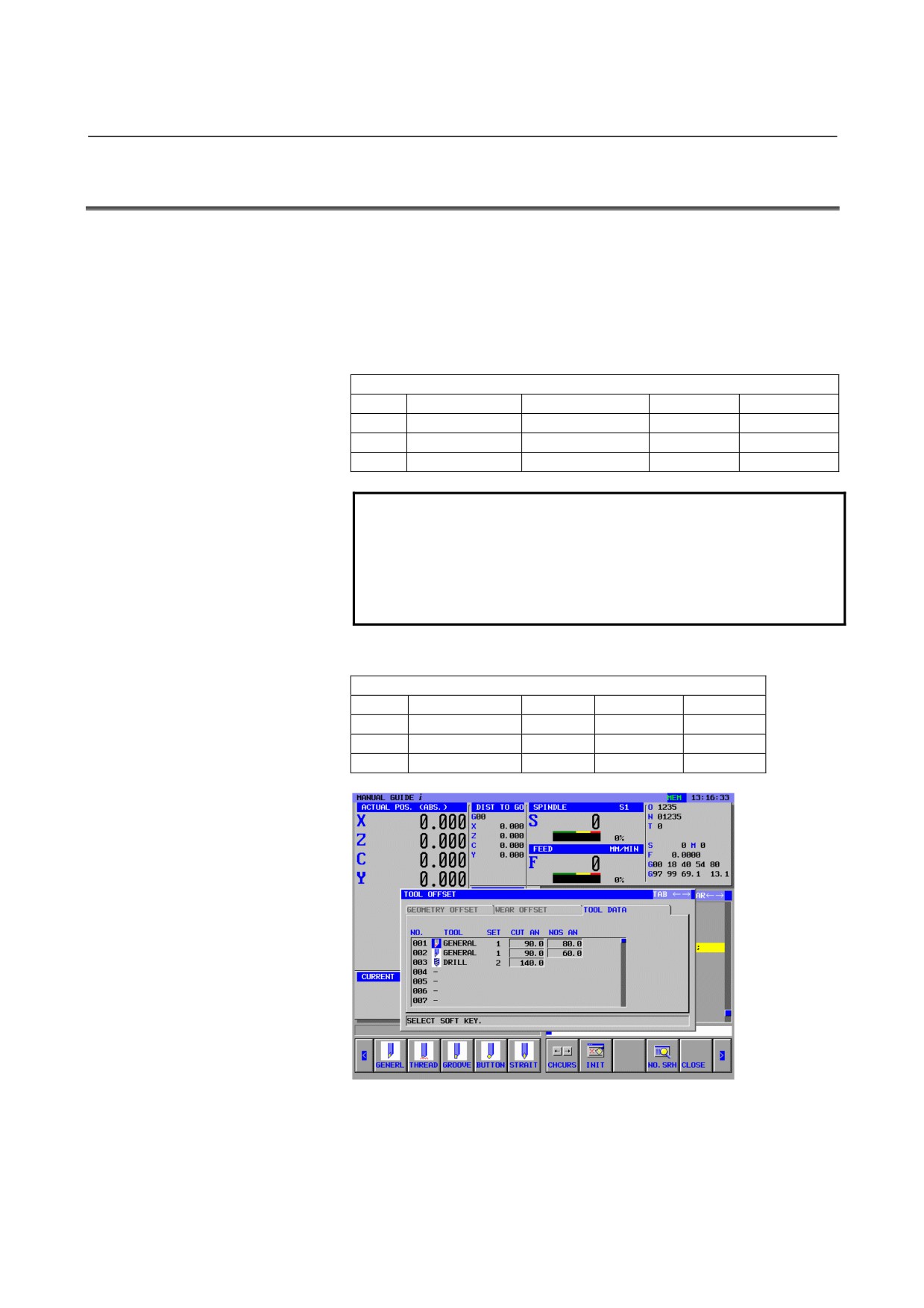
SETTING OF TOOL DATA
Set the necessary tool data. These tool data are used for displaying
tool form of animation and calculation of cutting angle in the cycle
machining.
T0101 : General purpose roughing tool
T0202 : General purpose finishing tool
T0303 : Drilling tool
Display “TOOL OFFSET” window by [T-OFS]
GEOMETRY OFFSET
NO.
X-AXIS
Z-AXIS
RADIUS
VIRT.TIP
001
-200.000
-300.000
0.800
3
002
-210.000
-310.000
0.400
3
003
-220.000
-330.000
3.000
0
NOTE
1 The above offset data are just an example, and they
cannot be used for actual machining.
2 The above offset number 003 is used for drilling
tool, and if you use it for animation, you must set the
radius amount of the drill to radius offset data.
Display “TOOL DATA” tab by pushing cursor key →
TOOL DATA
NO.
TOOL
SET
CUT AN
NOS AN
001
GENERAL
1
90.0
80.0
002
GENERAL
1
90.0
80.0
003
DRILL
2
140.0
- 695 -
2.LATHE
EXAMPLE OF PROGRAMMING
B-63874EN/05
2.5
CREATING OF PART PROGRAM
In the MANUAL GUIDE i , background editing can be used, but in
this section, part program creating operations are described by using
foreground editing.
2.5.1
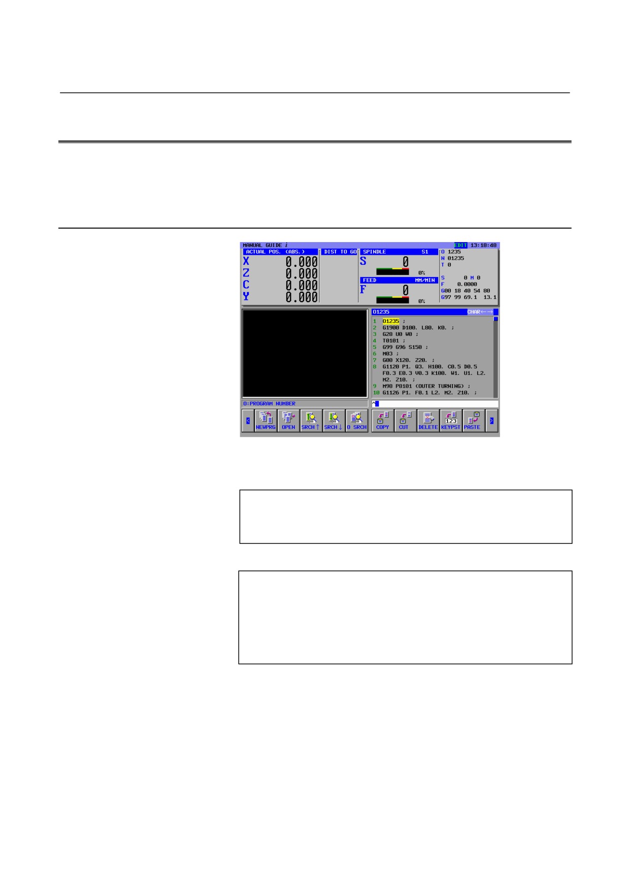
Creating New Part Program
Create a new part program of O1234.
1. In case of creating a new part program directly
Select EDIT mode by using a mode-selecting switch on a machine-operating panel
[NEWPRG]
(CREATE NEW PROGRAM)
1234 [CREATE]
(NEW PROGRAM NO.)
2. In case of creating a new part program on the program list window
Select EDIT mode by using a mode-selecting switch on a machine-operating panel
[O-LIST]
(OPEN PROGRAM)
[NEW]
(CREATE NEW PROGRAM)
1234 [CREATE]
(NEW PROGRAM NO.)
Select the newly entered program by ↓
[OPEN]
- 696 -
B-63874EN/05
EXAMPLE OF PROGRAMMING
2.LATHE
2.5.2
Operations of “START” Menu
By pushing [START] in the soft-key menu for turning machining, the
window “INSERT STARTING COMMAND FOR TURNING” with
the following tabs is displayed.
<START>
: Fixed form sentence menu used for the top of part
program or each machining process.
<BLANK> : Blank form menu, which is necessary for animation.
2.5.2.1
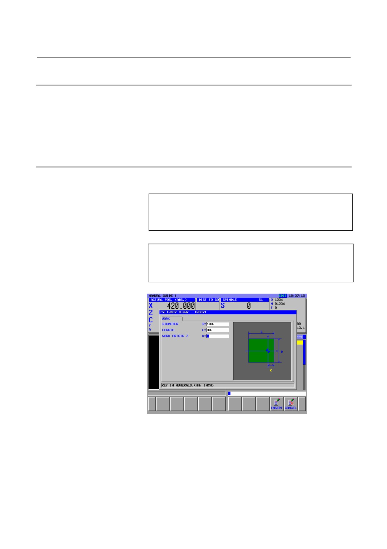
Entering blank form data
By selecting a tab <BLANK> by cursor key, blank form menu is
displayed.
(INSERT STARTING COMMAND FOR TURNING)
<BLANK>
↓
<<2.CYLINDER BLANK FIGURE>>
[SELECT]
Enter blank form data as a round bar.
(CYLINDER BLANK)
100 INPUT
(DIAMETER)
80 INPUT
(LENGTH)
0 INPUT
(WORK ORIGIN)
[INSERT]
- 697 -

2.LATHE
EXAMPLE OF PROGRAMMING
B-63874EN/05
2.5.3
Entering Tool Changing and Spindle Rotating Blocks for
Turning Machining
2.5.3.1 Entering in ISO-code form directly
It is difficult to define the action of tool changing, spindle rotation,
approaching and releasing generally because there are many
difference depending on machine configuration. So, using ISO-code
form program can realize more flexible and safety part program.
G28 U0 W0 ; INSERT
(Reference position return)
T0101 ; INSERT
(Tool change)
G99 G96 S150 ; INSERT
(Constant surface speed control, mm/rev mode)
M03 ; INSERT
(Spindle rotation)
G00 X120. Z20. ; INSERT
(Approaching)
2.5.3.2 Entering by fixed form sentence menu
ISO-code form part program can be entered from the fixed form
sentence menu. But, in such a case, proper fixed form sentence must
be prepared in advance.
(Soft-key group for Turning cycle menu)
[START]
<START>
↓
<<1.START PROCEDURE>>
[INSERT]
NOTE
There may be a case that undefined value is
entered by “?” in the fixed form sentence menu, so
in this case, you need to replace the “?” by proper
value can be used in actual machining.
Place the cursor to the address with “?”, enter
numeric data, then push “ALTER”.
- 698 -
B-63874EN/05
EXAMPLE OF PROGRAMMING
2.LATHE
2.5.4
Entering Outer Roughing Process
2.5.4.1 Entering outer roughing cycle block
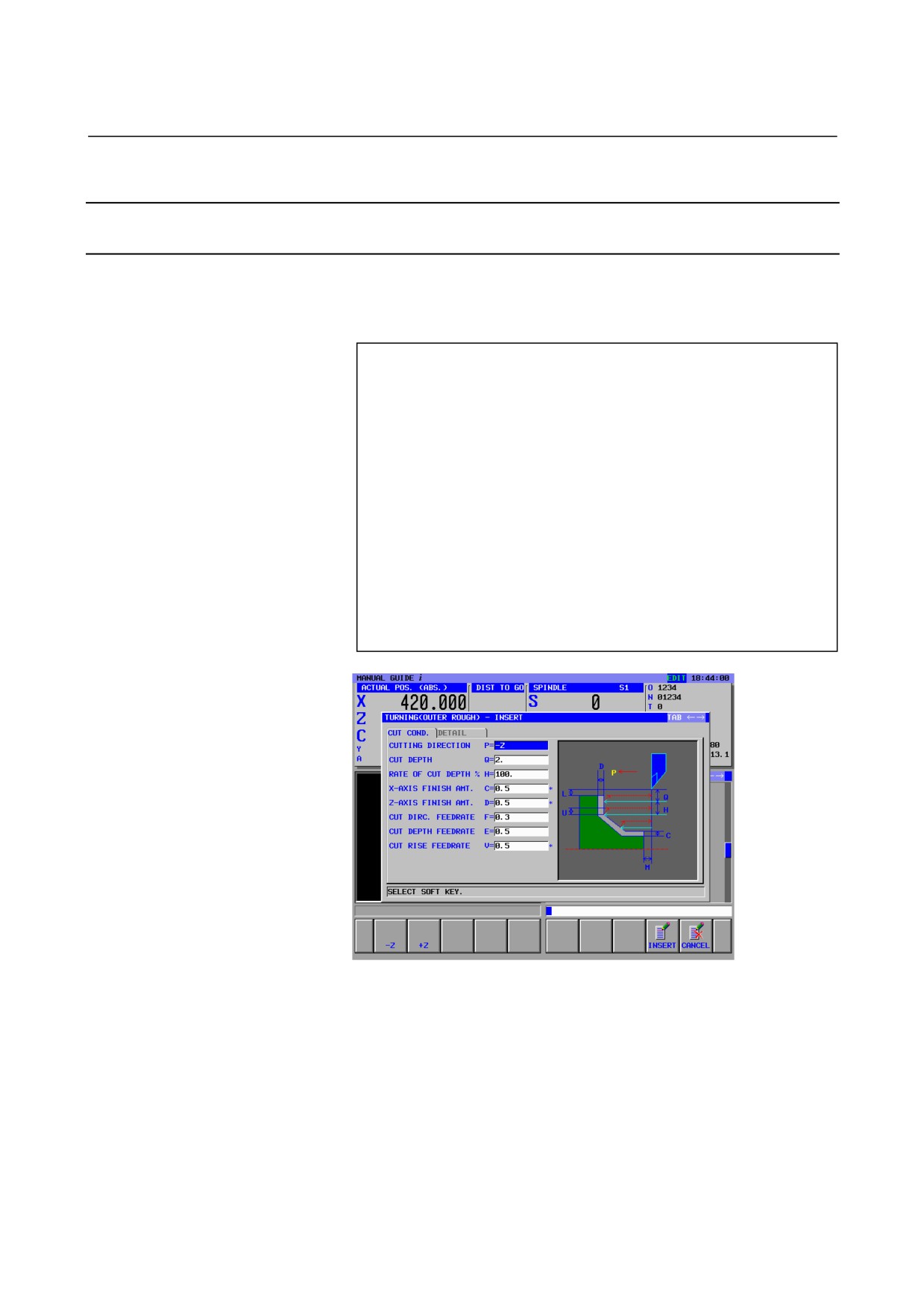
Enter the 1st process : outer roughing by a general purpose roughing
tool (T0101).
Enter machining type, cutting condition and so on.
(Soft-key group for Turning cycle menu)
[CYCLE]
→
<TURNING>
↓
<<1.TURNING(OUTER ROUGH)>>
[SELECT]
(TURNING(OUTER ROUGH) - INSERT)
<CUT COND.>
[-Z]
(CUTTING DIRECTION)
2 INPUT
(CUT DEPTH)
INPUT
(RATE OF CUT DEPTH %)
.5 INPUT
(X-AXIS FINISH AMT.)
.5 INPUT
(Z-AXIS FINISH AMT.)
.3 INPUT
(CUT DIRC. FEEDRATE)
.5 INPUT
(CUT DEPTH FEEDRATE)
.5 INPUT
(CUT RISE FEEDRATE)
[INSERT]
- 699 -
2.LATHE
EXAMPLE OF PROGRAMMING
B-63874EN/05
NOTE
1 In the cycle machining data menu window, all data
excepting cutting condition data are set
automatically. However, the data entered at
previously entered cycle of same kind are copied,
so you must enter the data if you have not entered
the same kind of cycle.
2 In the cycle machining data menu window, 2 tabs,
<CUT COND.> and <DETAIL>, are displayed.
In the <CUT COND.>, all data must be set. In the
<DETAIL>, all data are automatically set, so check
those data and modify them if necessary only
- 700 -

B-63874EN/05
EXAMPLE OF PROGRAMMING
2.LATHE
2.5.4.2
Entering figure for outer roughing
By inserting the outer roughing cycle machining block, the window of
free form entering is displayed, so enter the final figure of machining.
(ZX PLANE TURNING FIGURE - INSERT)
(START POINT - INSERT)
31 INPUT
(START POINT DX)
0 INPUT
(START POINT Z)
[OK]
[LINE]
(LINE - INSERT)
[L-UP]
(LINE DIRECTION)
35 INPUT
(END POINT DX)
INPUT
(END POINT Z)
45 INPUT
(ANGLE)
[OK]
[LINE]
(LINE - INSERT)
[LEFT]
(LINE DIRECTION)
[OK]
[CR]
(CORNER R - INSERT)
3 INPUT
(CORNER RADIUS)
[OK]
[LINE]
(LINE - INSERT)
[L-UP]
(LINE DIRECTION)
60 INPUT
(END POINT DX)
-30 INPUT
(END POINT Z)
60 INPUT
(ANGLE)
[OK]
[LINE]
(LINE - INSERT)
[LEFT]
(LINE DIRECTION)
[OK]
[CR]
(CORNER R - INSERT)
3 INPUT
(CORNER RADIUS)
[OK]
[LINE]
(LINE - INSERT)
[L-UP]
(LINE DIRECTION)
100 INPUT
(END POINT DX)
-50 INPUT
(END POINT Z)
80 INPUT
(ANGLE)
[OK]
After entering all the part figures for machining target, enter blank
figure. When you use a preformed workpiece such like an cast iron,
the most suitable cutting path can be made by entering the blank
figure of the preformed workpiece.
- 701 -