FANUC MANUAL GUIDE i. OPERATOR’S MANUAL - page 7
9.MACHINING SIMULATION AND DRAWING DURING MACHINING OPERATION
B-63874EN/05
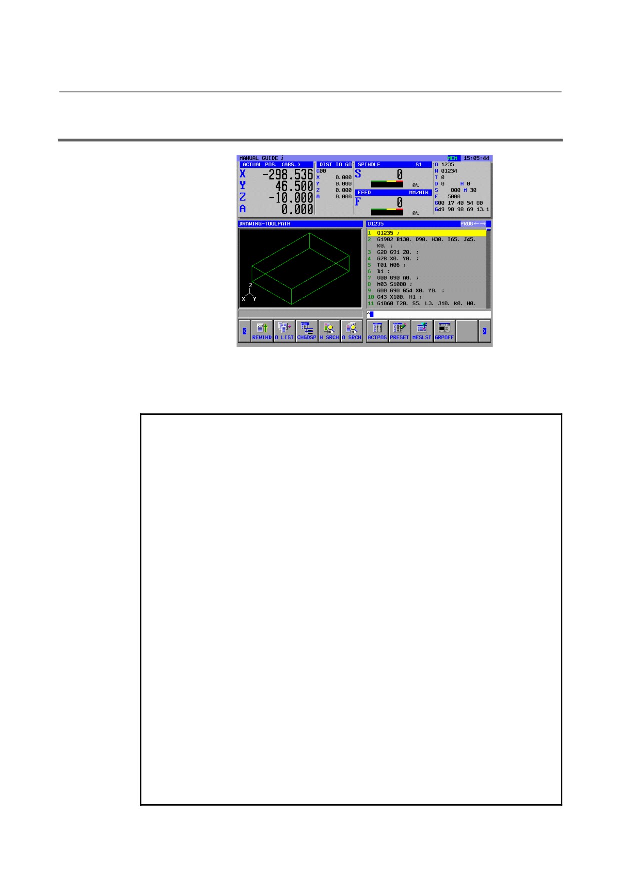
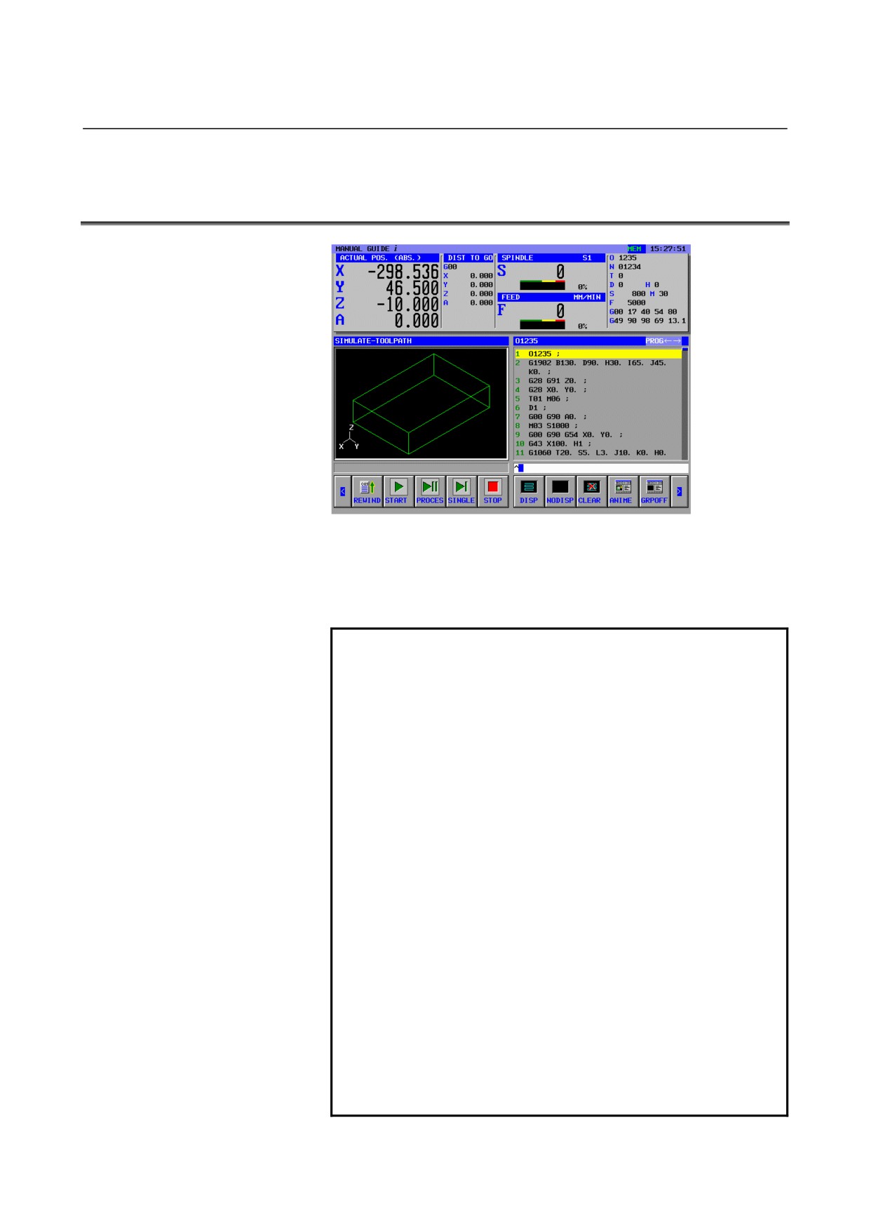
Pressing [AGRPOFF] in the machining simulation, animation and tool
path drawing, or drawing during machining mode, the screen gets
back to the memory mode screen.
- 162 -
B-63874EN/05
OPERATION
9.MACHINING SIMULATION AND DRAWING DURING MACHINING
9.1
DRAWING DURING MACHINING (TOOL PATH)
While a machining operation is being performed on the machine, the
tool path can be drawn. This function is available also during machine
lock and dry run operation.
NOTE
1
To perform drawing during machining, open the window for drawing
during machining by pressing [GRP ON] before starting machining
operation.
2
If a coordinate system change is specified in the program during
drawing, drawing is performed without changing the coordinate
system.
3
In the drawing during machining, when the workpiece specifying
block is executed, form of a workpiece is drawn in form of wire
frame. Drawing color of the workpiece can be specified by the
parameter No.14773.
4
When a simulation window is opened, a blank figure drawing at the
last drawing is displayed. However, if bit 4 of parameter No. 27310 is
set to 1, no blank figure is displayed when a simulation window is
opened.
5
Tool path drawing with a multi-path system is performed only at the
selected path for displaying. And a simulation window is initialized if
the selected path for displaying is changed. So if the selected path
for displaying is changed in displaying a free blank figure, the
drawing is initialized for a column figure which encloses it.
6
Path drawing is performed using values in the workpiece coordinate
system. Coordinates that allow for tool compensation (cutter
compensation, tool length compensation, geometry compensation,
and wear compensation), tool tip control, or the like are not used for
drawing.
7
This function cannot be used with the MANUAL GUIDE i simulator
for the personal computer.
- 163 -
9.MACHINING SIMULATION AND DRAWING DURING MACHINING OPERATION
B-63874EN/05
When drawing during machining (tool path) is selected, the soft keys
shown below appear. Pressing the leftmost soft key
[<] or the
rightmost soft key [>] changes the page of the soft key display to the
second or third page.
1st page soft-keys :
REWIND
START
PROCES
SINGLE
STOP
INIT
CUT DSP
INTERF
TLPATH
GRPOFF
2nd page soft-keys :
LARGE
SMALL
AUTO
ROTATE
←MOVE
MOVE→
↑MOVE
↓MOVE
CENTER
3rd page soft-keys :
DISP
NODISP
CLEAR
WK SET
T-OFS
SETING
9.1.1
Program Selection Operation and Other Operations in
Drawing during Machining
REWIND
O LIST
CHGDSP
N SRCH
O SRCH
ACTPOS
PRESET
MESLST
GRPOFF
1st page Soft keys are used for operations such as selection of a
program. These key operations are the same as the operations in the
MEM mode, so see the sections listed below.
To close the window for drawing during machining and stop the mode
for drawing during machining, press [GRPOFF].
6.1 REWINDING A MACHINING PROGRAM
6.2 EDITING WITH THE MACHINING PROGRAM LIST
6.3 SEARCHING FOR A SEQUENCE NUMBER IN A PROGRAM
6.4 SELECTING A PROGRAM FOR MACHINING OPERATION
6.5 CHANGING THE CURRENT POSITION DISPLAY
6.6 PRESETTING RELATIVE COORDINATES
6.7 DISPLAYING MEASUREMENT RESULTS
- 164 -
B-63874EN/05
OPERATION
9.MACHINING SIMULATION AND DRAWING DURING MACHINING
9.1.2
Selecting Whether to Display the Tool Path or Not in Drawing
during Machining
DISP
NODISP
CLEAR
WK SET
T-OFS
SETING
3rd page soft keys mainly allow you to select whether to display the
tool path or not.
For [SETING], see Chapter 10, "SETTING DATA," in Part II.
[NODISP] : As soon as this soft key is pressed, drawing of the tool
path is stopped. The tool path is not drawn until [DISP] is
pressed next.
[DISP]
: As soon as this soft key is pressed, drawing of the tool
path is started.
Remark) Only necessary tool path portions can be drawn by
using [DISP] and [NODISP].
[CLEAR] : Erase the tool path drawn so far. Immediately after this
soft key is pressed, tool path drawing is displayed.
9.1.3
Scaling, Movement, and Other Operations in Drawing during
Machining
LARGE
SMALL
AUTO
ROTATE
←MOVE
MOVE→
↑MOVE
↓MOVE
CENTER
2nd soft keys allow you to perform scaling and movement of a tool
path drawing as well as selection of a drawing coordinate system.
NOTE
The operations explained below must be performed
before tool path drawing is started.
1) Scaling and movement
[LARGR]
: Increase the drawing magnification.
[SMALL]
: Decrease the drawing magnification
[AUTO]
: When the blank form block for animation has been
input to the machining program, perform automatic
scaling so that the blank figure is fit in the window.
NOTE
If a blank form for animation has been entered,
automatic scaling is performed when the
corresponding block is executed for the first
time.
- 165 -
9.MACHINING SIMULATION AND DRAWING DURING MACHINING OPERATION
B-63874EN/05
[←MOVE] : Move the viewpoint leftward. As a result, the tool
path drawn moves rightward.
[MOVE→] : Move the viewpoint leftward. As a result, the tool
path drawn moves leftward.
[↑MOVE]
: Move the viewpoint upward. As a result, the tool
path drawn moves downward.
[↓MOVE]
: Move the viewpoint downward. As a result, the
tool path drawn moves upward.
[CENTER] : Set the center of the tool path to the center of the
window.
2) Selecting a drawing coordinate system
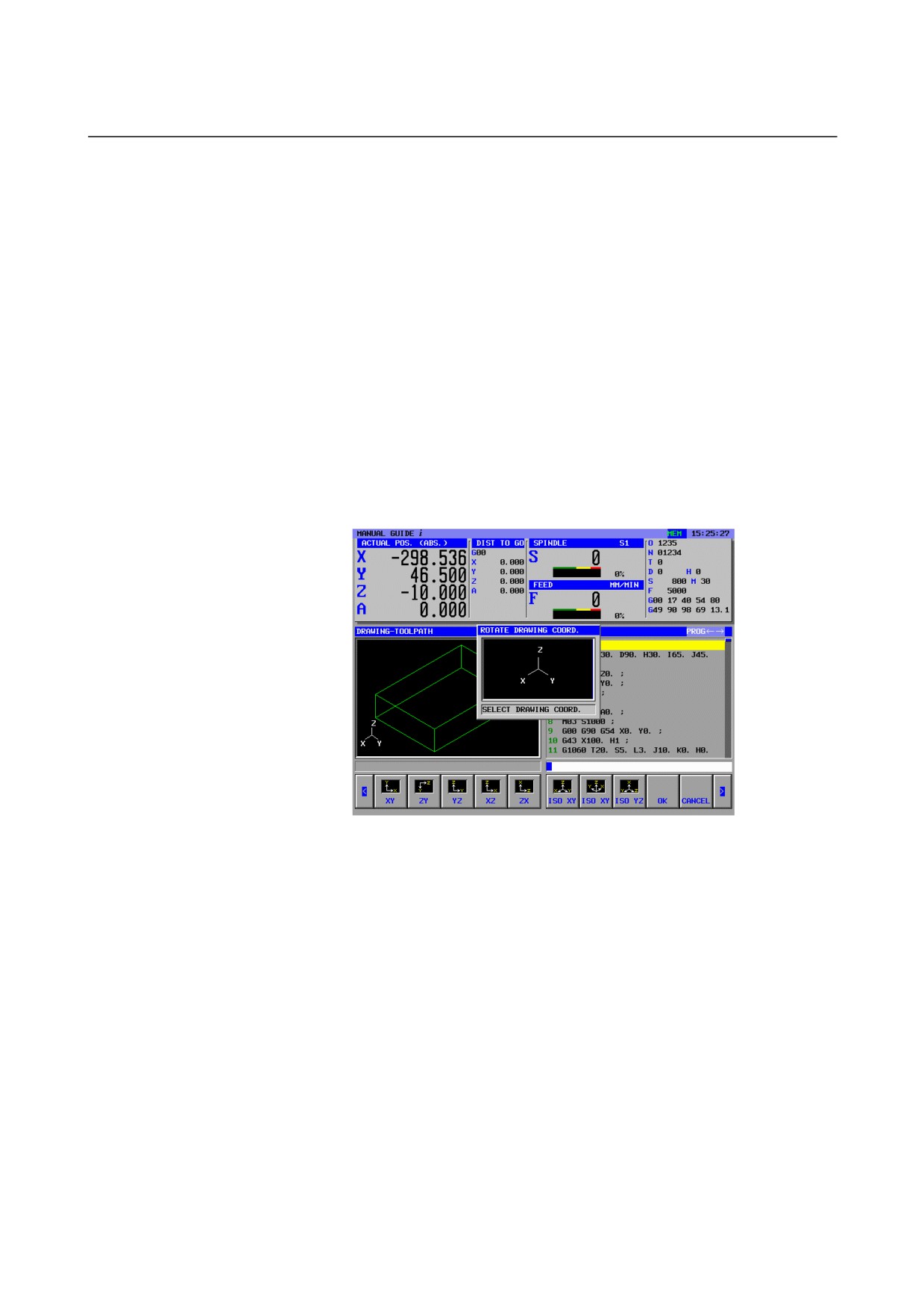
[ROTATE] : Display the soft keys shown below for selecting
the drawing coordinate system. A window for
describing drawing coordinate systems is also
displayed.
- 166 -
B-63874EN/05
OPERATION
9.MACHINING SIMULATION AND DRAWING DURING MACHINING
XY
ZY
YZ
XZ
ZX
ISO XY
ISO XY
ISO YZ
OK
CANCEL
↑
↓
←
→
OK
CANCEL
[XY]
: Select the XY plane.
[ZY]
: Select the ZY plane.
[YZ]
: Select the YZ plane.
[XZ]
: Select the XZ plane.
[ZX]
: Select the ZX plane.
[ISO XY]
: Select an equiangular coordinate system with the
positive direction of the Z-axis facing up.
[ISO XY]
: Select an equiangular coordinate system with the
positive direction of the Z-axis facing up. But, the
view point is opposed to the above one.
[ISO YZ]
: Select an equiangular coordinate system with the
positive direction of the X-axis facing up.
[OK]
: Perform drawing in the coordinate system selected
by one of the above soft keys.
[CANCEL] : Cancel the coordinate system selected by one of
the above soft keys and use the original coordinate
system for drawing.
[↑]
: Make a counterclockwise rotation by selecting the
right direction viewed when you face the screen as
the center axis.
[↓]
: Make a clockwise rotation by selecting the right
direction viewed when you face the screen as the
center axis.
[←]
: Make a counterclockwise rotation by selecting the
upward direction viewed when you face the screen
as the center axis.
[→]
: Make a clockwise rotation by selecting the upward
direction viewed when you face the screen as the
center axis.
[
]
: Make a clockwise rotation by selecting the
direction toward you viewed when you face the
screen as the center axis.
[
]
: Make a counterclockwise rotation by selecting the
direction toward you viewed when you face the
screen as the center axis.
NOTE
A rotation is made according to the unit specified in
parameter No. 14716.
- 167 -
9.MACHINING SIMULATION AND DRAWING DURING MACHINING OPERATION
B-63874EN/05
9.2
MACHINING SIMULATION (TOOL PATH) (FOR Series
16i/18i/21i)
The path of the tool in a machining program can be drawn without
performing actual machining operation on the machine (machining
simulation). This section is an explanation for Series
16i/18i/21i
model B. In the case of Series 30i, see Section 9.4.
NOTE
1
To perform machining simulation, select the MEM
mode with the mode switch on the machine
operator's panel.
2
If a coordinate system change is specified in the
program during simulation, simulation is performed
without changing the coordinate system.
3
In the drawing during machining, when the
workpiece specifying block is executed, form of a
workpiece is drawn in form of wire frame. Drawing
color of the workpiece can be specified by the
parameter No.14773.
4
When a simulation window is opened, a blank
figure drawing at the last drawing is displayed.
However, if bit 4 of parameter No. 27310 is set to
1, no blank figure is displayed when a simulation
window is opened.
5
Tool path drawing with a multi-path system is
performed only at the selected path for displaying.
And a simulation window is initialized if the
selected path for displaying is changed. So if the
selected path for displaying is changed in
displaying a free blank figure, the drawing is
initialized for a column figure which encloses it.
- 168 -
B-63874EN/05
OPERATION
9.MACHINING SIMULATION AND DRAWING DURING MACHINING
NOTE
6 Path drawing is performed using values in the
workpiece coordinate system. Coordinates that
allow for tool compensation (cutter compensation,
tool length compensation, geometry compensation,
and wear compensation), tool tip control, or the like
are not used for drawing.
7 Simulation cannot be performed in any of control
modes of the high-speed and high-precision
functions (commands for advanced preview
control, AI advanced preview control, AI contour
control, AI nano contour control, high-precision
contour control, AI high-precision contour control,
and AI nano high-precision contour control).
8 In simulation of a program having a sequence of
contiguous small blocks, drawing requires longer
processing time, possibly causing machining time
to become longer than actual machining time.
To close the machining simulation (tool path) window and stop the
drawing operation of machining simulation, press [GRPOFF].
When machining simulation (tool path) is selected, the soft keys
shown below appear. Pressing the leftmost soft key
[<] or the
rightmost soft key [>] changes the page of the soft key display to the
second, third, or fourth page.
1st page soft-keys :
REWIND
START
PROCES
SINGLE
STOP
DISP
NODISP
CLEAR
ANIME
GRPOFF
2nd page soft-keys :
LARGE
SMALL
AUTO
ROTATE
←MOVE
MOVE→
↑MOVE
↓MOVE
CENTER
3rd page soft-keys :
WK SET
T-OFS
SETING
4th page soft-keys :
REWIND
O-LIST
CHGDSP
N SRCH
O SRCH
ACTPOS
PRESET
MESLST
- 169 -
9.MACHINING SIMULATION AND DRAWING DURING MACHINING OPERATION
B-63874EN/05
9.2.1
Program Selection Operation and Other Operations in
Machining Simulation (Tool Path)
WK SET
T-OFS
SETING
REWIND
O-LIST
CHGDSP
N SRCH
O SRCH
ACTPOS
PRESET
MESLST
The soft keys on the 3rd and 4th pages are used for operations such as
program selection and offset data setting. These key operations are the
same as the operations in the MEM mode, so see the sections listed
below.
6.1 REWINDING A MACHINING PROGRAM
6.2 EDITING WITH THE MACHINING PROGRAM LIST
6.3 SEARCHING FOR A SEQUENCE NUMBER IN A PROGRAM
6.4 SELECTING A PROGRAM FOR MACHINING OPERATION
6.5 CHANGING THE CURRENT POSITION DISPLAY
6.6 PRESETTING RELATIVE COORDINATES
6.7 DISPLAYING MEASUREMENT RESULTS
9.2.2
Execution Operations in Machining Simulation (Tool Path)
REWIND
START
PAUSE
SINGLE
STOP
DISP
NODISP
CLEAR
ANIME
GRPOFF
On the 1st page soft key, you can perform operations related to
execution in machining simulation (tool path).
For [SETING], see Chapter 10, "SETTING DATA," in Part II.
[REWIND] : Return to the beginning of the machining program
selected for machining simulation.
[START]
: Start machining simulation for the currently selected
machining program.
[PAUSE]
: Stop machining simulation temporarily.
[SINGLE]
: Cause a single-block stop when machining simulation is
performed in the continuous mode. When machining
simulation is in the stopped state, this soft key starts
machining simulation in the single-block mode.
[STOP]
: End machining simulation.
[NODISP]
: From the block immediately after this soft key is
pressed, suppress tool path drawing. Tool path drawing
is not performed until [DISP] is pressed next.
- 170 -
B-63874EN/05
OPERATION
9.MACHINING SIMULATION AND DRAWING DURING MACHINING
[DISP]
: From the block immediately after this soft key is
pressed, start drawing of the tool path.
Remark) Only necessary tool path portions can be drawn by
using [DISP] and [NODISP].
[CLEAR]
: Erase the tool path drawn so far. Tool path drawing
immediately after this soft key is pressed is displayed.
NOTE
By setting bit 0 (PRC) of parameter No. 27310 to 1,
[PAUSE] can be changed to [PROCES] (for
temporarily stopping machining simulation at a
block specifying M01;).
9.2.3
Scaling, Movement, and Other Operations in Machining
Simulation (Tool Path)
LARGE
SMALL
AUTO
ROTATE
←MOVE
MOVE→
↑MOVE
↓MOVE
CENTER
2nd page soft keys allow you to perform scaling and movement for
machining simulation (tool path) as well as selection of a drawing
coordinate system. These operations are the same as those in drawing
during machining. For details, see Subsection 9.1.3.
NOTE
1 Operations such as scaling, movement, and
selection of a drawing coordinate system must be
performed before machining simulation (tool path)
is started.
2 If a coordinate system change is specified in the
program during simulation, simulation is performed
without changing the coordinate system.
- 171 -
9.MACHINING SIMULATION AND DRAWING DURING MACHINING OPERATION
B-63874EN/05
9.3
MACHINING SIMULATION (ANIMATED) (FOR Series
16i/18i/21i)
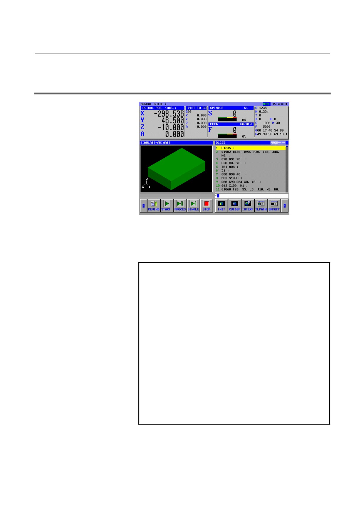
Animated simulation of a machining operation by a machining
program can be performed without performing actual machining
operation on the machine. This section is an explanation for Series
16i/18i/21i-MODEL B. In the case of Series 30i, see Section 9.5.
NOTE
1 To perform machining simulation, select the MEM
mode with the mode switch on the machine
operator's panel.
2 If a coordinate system change is specified in a
program under simulation, whether to perform
simulation with the same coordinate system or a
changed coordinate system can be chosen using
bit 1 (ACD) of parameter No. 27311. For details,
see Section 9.8.
3 When a program that is composed by repeated
minute line segments like a program outputted by
CAD/CAM is executed, sometimes the speed of
simulation much slows down. In this case, please
set tool motion unit to parameter No. 27323 by dot.
When tool moves over the value of this parameter
on screen, the screen is updated and the speed will
be accelerated. But, if the value of the parameter is
too large, the resolution will decrease.
- 172 -
B-63874EN/05
OPERATION
9.MACHINING SIMULATION AND DRAWING DURING MACHINING
NOTE
4 A tool tip position in animated simulation has
coordinates of values in the workpiece coordinate
system. Coordinates that allow for tool
compensation (cutter compensation, tool length
compensation, geometry compensation, and wear
compensation), tool tip control, or the like are not
used for drawing.
5 Simulation cannot be performed in any of control
modes of the high-speed and high-precision
functions (commands for advanced preview
control, AI advanced preview control, AI contour
control, AI nano contour control, high-precision
contour control, AI high-precision contour control,
and AI nano high-precision contour control).
6 In simulation of a program having a sequence of
contiguous small blocks, drawing requires longer
processing time, possibly causing machining time
to become longer than actual machining time.
To close the machining simulation (animated) window and stop the
drawing operation of machining simulation, press [GRPOFF].
When machining simulation (animated) is selected, the soft keys
shown below appear. Pressing the leftmost soft key
[<] or the
rightmost soft key [>] changes the page of the soft key display to the
second, third, or fourth page.
1st page soft-keys :
REWIND
START
PROCES
SINGLE
STOP
INIT
CUT DSP
INTERF
TLPATH
GRPOFF
2nd page soft-keys :
LARGE
SMALL
AUTO
REVERS
ROTATE
←MOVE
MOVE→
↑MOVE
↓MOVE
CENTER
3rd page soft-keys :
WK SET
T-OFS
SETING
4th page soft-keys :
REWIND
O LIST
CHGDSP
N SRCH
O SRCH
ACTPOS
PRESET
MESLST
- 173 -
9.MACHINING SIMULATION AND DRAWING DURING MACHINING OPERATION
B-63874EN/05
9.3.1
Program Selection Operation and Other Operations in
Machining Simulation (Animated)
WK SET
T-OFS
SETING
REWIND
O LIST
CHGDSP
N SRCH
O SRCH
ACTPOS
PRESET
MESLST
The soft keys on the 3rd and 4th pages are used for operations such as
program selection and offset data setting. These key operations are the
same as the operations in the MEM mode, so see the sections listed
below.
6.1 REWINDING A MACHINING PROGRAM
6.2 EDITING WITH THE MACHINING PROGRAM LIST
6.3 SEARCHING FOR A SEQUENCE NUMBER IN A PROGRAM
6.4 SELECTING A PROGRAM FOR MACHINING OPERATION
6.5 CHANGING THE CURRENT POSITION DISPLAY
6.6 PRESETTING RELATIVE COORDINATES
6.7 DISPLAYING MEASUREMENT RESULTS
9.3.2
Execution Operations in Machining Simulation (Animated)
REWIND
START
PROCES
SINGLE
STOP
INIT
CUT DSP
INTERF
TLPATH
GRPOFF
On the 1st page soft keys, you can perform operations related to
execution in machining simulation
(animated). The operations of
[REWIND], [START], [PAUSE], [SINGLE], and [STOP] are the
same as the operations in machining simulation (tool path). For details,
see Subsection 9.2.3.
[INIT]
: Initialize the machined blank used for animation.
[CUT DSP] : Lets you switch between 1/4 workpiece and entire
periphery for rod blanks and drilled rod blanks.
Before starting animated simulation, be sure to switch if
necessary.
[INTERF]
: Lets you select whether to make an interference check
during animated simulation. If an interference check is
enabled, a warning is displayed when the tool tip
collides with a workpiece during rapid traverse, and the
portion collided with the tool tip is displayed in the
same color as that of the tool.
- 174 -
B-63874EN/05
OPERATION
9.MACHINING SIMULATION AND DRAWING DURING MACHINING
NOTE
With bit 0 (ITF) of parameter No. 27311, you can
select continued operation (ITF = 0) or temporary
stop (ITF = 1) if tool interferes with the workpiece
during animation.
9.3.3
Scaling, Movement, and Other Operations in Machining
Simulation (Animated)
LARGE
SMALL
AUTO
REVERS
ROTATE
←MOVE
MOVE→
↑MOVE
↓MOVE
CENTER
The soft keys on the 2nd page allow you to perform scaling and
movement for machining simulation (animated) as well as selection of
a drawing coordinate system. These operations are the same as those
in drawing during machining. For details, see Subsection 9.1.3.
[REVERS] : Change the viewpoint of the blank in animation to the
exactly opposite position. You can use this soft key
when, during machining with a sub-spindle or
machining with the C-axis rotated, for example, you
want to see animation from the opposite side.
NOTE
1 Although [REVERS] may be used even during
machining simulation, switching will sometimes be
delayed depending on the CNC status.
2 Operations such as scaling, movement, and
selection of a drawing coordinate system must be
performed before machining simulation (tool path)
is started.
9.3.4
Notes on Machining Simulation
During the execution of drawing, the system is automatically placed in
the machine locked state. During the execution of drawing, no
machine control signals are output by auxiliary and other functions,
but control signals such as "OP," "STL," "SPL," "RST," and "AL"
may be output. During the execution of drawing, the
drawing-in-progress signal "CKGRP," shown below, is output. If the
control signals that may be output during the execution of drawing
affect machine control, the PMC Ladder program must be modified so
that these signals are ignored, by using the drawing-in-progress signal.
#7
#6
#5
#4
#3
#2
#1
#0
F62
CKGRP
CKGRP Indicates that a dynamic graphics display is being drawn for check
purposes.
In order to distinguish the executing state of the program, machining
- 175 -

9.MACHINING SIMULATION AND DRAWING DURING MACHINING OPERATION
B-63874EN/05
custom macro program can refer to the following system variable
#3010.
System variable
Value
Executing State
#3010
0
Normal condition(Other than the following
status)
1
Executing automatic operation(Including
Drawing during Machining)
4
Executing machining simulation(Animated,
Tool Path)
- 176 -
B-63874EN/05
OPERATION
9.MACHINING SIMULATION AND DRAWING DURING MACHINING
9.4
MACHINING SIMULATION (TOOL PATH) (FOR Series 30i)
During machining, the tool path of another program can be drawn.
With Series 30i MANUAL GUIDE i, the terms related to operation
and drawing are defined as follows:
Automatic operation
Operation performed for actual machining
Drawing during machining
Tool path drawing during automatic operation
Background operation
Virtual operation performed for simulation. This
operation can be performed simultaneously with
automatic operation.
Machining simulation
Machining simulation in background operation
(generic term for tool path drawing and animated
simulation)
Tool path drawing
Machining simulation for drawing the tool path in
background operation
Animated drawing
Machining simulation for animated simulation of
background operation
With FANUC Series 30i MANUAL GUIDE i, machining simulation
can be performed in the MEM mode and EDIT mode. When each
mode is selected, the machining simulation screen can be displayed
using the operation described below.
•
MEM mode
REWIND
O-LIST
N SRCH
O SRCH
ACTPOS
PRESET
MCHDRW
SIMLAT
Pressing
[SIMLAT] displays the machining simulation
(animated) screen and the soft keys for machining simulation.
•
EDIT mode
REWIND
CHGDSP
LINENO
SIMLAT
SETING
Pressing
[SIMLAT] displays the machining simulation
(animated) screen and the soft keys for machining simulation.
- 177 -
9.MACHINING SIMULATION AND DRAWING DURING MACHINING OPERATION
B-63874EN/05
NOTE
1
A program subject to simulation is placed in the
background editing selection state. So, if
background editing is in progress when the
[SIMLAT] soft key is pressed, the simulation screen
cannot be displayed. (The warning message "CAN
NOT OPERATE ON BG EDIT" is displayed.)
Terminate background editing then press the
[SIMLAT] soft key.
2
A program selected when the [SIMLAT] soft key is
pressed is the program being selected in the
foreground.
3
When machining simulation is terminated by
pressing the [GRPOFF] soft key, the program
selected for drawing is closed, and the program
selected in the foreground is placed in the
foreground selection state.
4
If the screen display is switched to another screen
during drawing, machining simulation is terminated.
5
If the machining simulation screen is displayed
again after the machining simulation screen is
terminated, the results of the previous simulation
are erased.
6
Animated simulation assumes that the tool tip is
placed at the current position. So, if the tool is
inclined with the tool inclination axis, drawing is
performed at a position different from the actual
tool position until the next move command is
specified for the tool tip. Coordinates that allow for
tool compensation (cutter compensation, tool
length compensation, geometry compensation, and
wear compensation), tool tip control, or the like are
not used for drawing.
7
Simulation cannot be performed in any of control
modes of the high-speed and high-precision
functions (commands for advanced preview
control, AI advanced preview control, AI contour
control, AI nano contour control, high-precision
contour control, AI high-precision contour control,
and AI nano high-precision contour control).
8
In simulation of a program having a sequence of
contiguous small blocks, drawing requires longer
processing time, possibly causing machining time
to become longer than actual machining time.
- 178 -
B-63874EN/05
OPERATION
9.MACHINING SIMULATION AND DRAWING DURING MACHINING
To close the machining simulation (tool path) window and stop the
drawing operation of machining simulation, press [GRPOFF].
When machining simulation (tool path) is selected, the soft keys
shown below appear. Pressing the leftmost soft key
[<] or the
rightmost soft key [>] changes the page of the soft key display to the
second, third, or fourth page.
1st page soft-keys :
REWIND
START
PAUSE
SINGLE
STOP
DISP
NODISP
CLEAR
ANIME
GRPOFF
2nd page soft-keys :
LARGE
SMALL
AUTO
ROTATE
↑MOVE
MOVE→
↑MOVE
↓MOVE
CENTER
3rd page soft-keys :
WK SET
T-OFS
SETING
4th page soft-keys
REWIND
O LIST
↑ SRCH
↓ SRCH
O SRCH
ACTPOS
PRESET
MESLST
- 179 -
9.MACHINING SIMULATION AND DRAWING DURING MACHINING OPERATION
B-63874EN/05
NOTE
1
The data displayed on the machining simulation
screen such as the current position and remaining
travel distance is not automatic operation state
data but is machining simulation data.
2
The machining simulation screen does not display
spindle information and feed information but
displays the next travel distance only.
3
On the machining simulation screen, the remaining
travel distance is 0 at all times.
4
To stop machining simulation, press the [STOP]
soft key. If RESET key is pressed, foreground
operation is reset.
5
If a blank registration command is executed in tool
path drawing during machining simulation, the
blank figure is displayed using a line (wire frame).
Use parameter No. 14773 to specify the display
color of the blank figure.
6
When the simulation window is displayed, the blank
figure data previously displayed is used for
drawing. However, when bit 4 of parameter No.
27310 is set to 1, no blank figure is displayed if the
simulation window is open.
7
In machining simulation performed with a multipath
system, the tool path of the displayed path only is
drawn. If the displayed path is switched during path
drawing, the drawing screen is initialized. So, if the
displayed path is switched when an arbitrary figure
blank is displayed, the blank is initialized to a round
rod figure enclosing the arbitrary figure.
8
If the animated simulation option is not selected, a
blank figure command is ignored, and no blank
figure (wire frame) is displayed.
9
When simulation is started from a midway point,
the modal state of the NC is not always executed
up to the midway point. So, if simulation is started
from a midway point, correct drawing operation
may not be performed.
In order to distinguish the executing state of the program, machining
custom macro program can refer to the following system variable
#3010.
System variable
Value
Executing State
#3010
0
Normal condition(Other than the following
status)
-1
Executing machining simulation(Animated,
Tool Path)
- 180 -
B-63874EN/05
OPERATION
9.MACHINING SIMULATION AND DRAWING DURING MACHINING
9.4.1
Program Selection Operation and Other Operations in
Machining Simulation (Tool Path)
WK SET
T-OFS
SETING
REWIND
O LIST
↑ SRCH
↓ SRCH
O SRCH
ACTPOS
PRESET
MESLST
The soft keys on the 3rd and 4th pages are used for operations such as
program selection and offset data setting. These operations are the
same as operations in the MEM mode. However, no data can be set
during machining simulation.
NOTE
1 A program subject to simulation is placed in the
background editing selection state. So, the selected
program is placed in the background editing selection
state.
2 Data such as offset data can be edited at all times
except during machining simulation. A modification to
data can affect program execution for automatic
operation. So, before editing data, ensure that the
data is not being used.
3 Offset data and coordinate system data is copied for
machining simulation, and such simulation-dedicated
data is used during machining simulation. Even if
such data is rewritten using G10, for example, the
actual data is not modified.
- 181 -
9.MACHINING SIMULATION AND DRAWING DURING MACHINING OPERATION
B-63874EN/05
9.4.2
Execution Operations in Machining Simulation (Tool Path)
REWIND
START
PAUSE
SINGLE
STOP
DISP
NODISP
CLEAR
ANIME
GRPOFF
On the 2nd page soft key, you can perform operations related to
execution in machining simulation (tool path).
[REWIND] : Return to the beginning of the machining program
selected for machining simulation.
[START]
: Start machining simulation for the currently selected
machining program.
[PAUSE]
: Stop machining simulation temporarily.
[SINGLE]
: Cause a single-block stop when machining simulation is
performed in the continuous mode. When machining
simulation is in the stopped state, this soft key starts
machining simulation in the single-block mode.
[STOP]
: End machining simulation.
[NODISP]
: From the block immediately after this soft key is
pressed, suppress tool path drawing. Tool path drawing
is not performed until [DISP] is pressed next.
[DISP]
: From the block immediately after this soft key is
pressed, start drawing of the tool path.
Remark) Only necessary tool path portions can be drawn by
using [DISP] and [NODISP].
[CLEAR]
: Erase the tool path drawn so far. Tool path drawing
immediately after this soft key is pressed is displayed.
NOTE
1 By setting bit 0 (PRC) of parameter No. 27310 to 1,
[PAUSE] can be changed to [PROCES] (for temporarily
stopping machining simulation at a block specifying
M01;).
9.4.3
Scaling, Movement, and Other Operations in Machining
Simulation (Tool Path)
The operations are the same as those operations performed with Series
16i/18i/21i-MODEL B. For details, see Subsection 9.2.3.
- 182 -
B-63874EN/05
OPERATION
9.MACHINING SIMULATION AND DRAWING DURING MACHINING
9.5
MACHINING SIMULATION (ANIMATED) (FOR Series 30i)
During machining, animated simulation can be performed for another
program.
The terms related to operation and drawing for tool path drawing
described in Section 9.4 are applicable. See Section 9.4.
With Series
30i MANUAL GUIDE i, machining simulation
(animated) can be performed in the MEM mode and EDIT mode. The
operation for displaying the machining simulation screen in each
mode is the same as for tool path drawing. See Section 9.4.
In order to distinguish the executing state of the program, machining
custom macro program can refer to the following system variable
#3010.
System variable
Value
Executing State
#3010
0
Normal condition(Other than the following
status)
-1
Executing machining simulation(Animated,
Tool Path)
9.5.1
Program Selection Operation and Other Operations in
Machining Simulation (Animated)
The operations are the same as those operations performed for tool
path drawing described in Section 9.4. See Section 9.4.
9.5.2
Execution Operations in Machining Simulation (Animated)
REWIND
START
PAUSE
SINGLE
STOP
INIT
CUTDSP
INTERF
TLPATH
GRPOFF
On the 1st page soft keys, you can perform operations related to
execution in machining simulation
(animated). The operations of
[REWIND], [START], [PAUSE], [SINGLE], and [STOP] are the
same as the operations in machining simulation (tool path). For details,
see Subsection 9.2.3.
[INIT]
: Initialize the machined blank used for animation.
[CUTDSP] : Lets you switch between 1/4 workpiece and entire
periphery for rod blanks and drilled rod blanks. Before
starting animated simulation, be sure to switch if
necessary.
[INTERF]
: Lets you select whether to make an interference check
during animated simulation. If an interference check is
enabled, a warning is displayed when the tool tip
collides with a workpiece during rapid traverse, and the
- 183 -
9.MACHINING SIMULATION AND DRAWING DURING MACHINING OPERATION
B-63874EN/05
portion collided with the tool tip is displayed in the
same color as that of the tool.
NOTE
With bit 0 (ITF) of parameter No. 27311, you can
select continued operation (ITF = 0) or temporary stop
(ITF = 1) if tool interferes with the workpiece during
animation.
9.5.3
Scaling, Movement, and Other Operations in Machining
Simulation (Animated)
The operations are the same as those operations performed with Series
16i/18i/21i-MODEL B. For details, see Subsection 9.3.3.
- 184 -
B-63874EN/05
OPERATION
9.MACHINING SIMULATION AND DRAWING DURING MACHINING
9.6
DATA HANDLED DURING MACHINING SIMULATION
(FOR Series 30i)
During machining simulation (background operation), data is handled
as indicated below.
<1>
Parameter
The same parameters are used for machining
simulation and automatic operation.
<2>
Tool compensation value
Data used for machining simulation differs from
Workpiece origin offset value
data used for automatic operation.
Extended workpiece origin offset value
Macro variable
Fixture offset data
<3>
Tool life management data
These data items are not used for machining
Tool number offset data
simulation.
3-dimensional error compensation data
<1> Parameter
The same parameters as used for automatic operation are used for
machining simulation. However, no parameter can be rewritten
in background operation. (If an attempt is made to rewrite a
parameter by programmable parameter input
(G10L50), a
warning (NC statement error (B.G.) is output.)
<2> Tool compensation value, workpiece origin offset value,
extended workpiece origin offset value, macro variable, etc.
Data used for background operation differs from data used for
automatic operation. When background operation is started, the
data for automatic operation is copied to produce data for
background operation. Afterwards, the data for background
operation and the data for automatic operation are handled
separately from each other. So, even when data is rewritten using
G10, for example, background operation and automatic operation
do not affect each other. Note, however, that data rewritten in
background operation is erased without being reflected in the
actual data (foreground data).
<3> Tool life management data, tool number offset data,
3-dimensional error compensation data
These data items are not used for background operation. So, if an
attempt is made to rewrite data by using G10, a warning (NC
statement error (B.G.)) is output.
- 185 -
9.MACHINING SIMULATION AND DRAWING DURING MACHINING OPERATION
B-63874EN/05
9.7
FUNCTIONS OPERATING DIFFERENTLY BETWEEN
MACHINING SIMULATION AND AUTOMATIC OPERATION
(FOR Series 30i)
The functions listed below are major functions that operate in
background operation and automatic operation differently from each
other. There are additional functions that operate differently.
<1> Custom macro
1)
Interface signal
#1000 to #1035 are always assumed to be 0 at all times.
2)
Message output
A message output with #3006 is not displayed but is
ignored.
3)
Clock
#3001 and #3002 are ignored. So, note that if a command as
indicated below is specified, for example, drawing does not
proceed:
#3001=1;
WHILE[#3001 LE100]DO1;
END1;
4)
Mirror image
#3007 is assumed to be 0 at all times.
5)
State during program restart operation
#3008 is assumed to be 0 at all times.
6)
External output command
BPRNT, DPRNT, POPEN, and PCLOS are ignored.
<2> Functions ignored
1)
G04 (Dwell)
2)
G20, G21 (Inch/metric conversion)
3)
Auxiliary function (M, S, T, B)
4)
G22,G23 (Stored stroke limit on/off)
5)
G10.1 (PMC data setting)
6)
G10.6 (Tool retraction data setting)
7)
G10.9 (Programmable diameter/radius switching)
8)
G81.1 (Chopping)
9)
G25/G26 (Spindle speed fluctuation detection on/off)
<3> Functions that operate differently in part
1)
G28 (automatic reference position return) is drawn up to a
midway point.
2)
G29 (automatic return from the reference position) is drawn
from a midway point.
3)
G27 (reference position return check) does not make a
reference position return check.
4)
Stored stroke limit checks are not made.
5)
G31
(skip function), and G31.1, G31.2, and G31.3
(multi-step skip) are drawn up to a specified position,
regardless of the skip signal.
6)
G60 (single direction positioning) is drawn directly up to a
specified position at all times even when the positioning
direction is reverse.
- 186 -
B-63874EN/05
OPERATION
9.MACHINING SIMULATION AND DRAWING DURING MACHINING
9.7.1
Functions That Cannot Be Used for Machining Simulation
<1> Functions that operate differently in background drawing
When the functions below are specified, the operations described
below are performed.
G02.2/G03.2 : Involute interpolation
Circular interpolation is performed.
G06.1 : Spline interpolation
Linear interpolation is performed.
When the functions below are specified, the operations described
below are performed.
G02.1/G03.1 : Circular threading B
Circular interpolation is performed. No rotation axis can
be drawn.
G02.3/G03.3 : Exponential interpolation
Linear interpolation is performed for a straight line only.
G07 : Hypothetical axis interpolation
Circular interpolation is performed.
<2> Functions that disable background drawing
When the functions below are specified, a warning
(NC
statement error (B.G.)) is output, and background drawing stops.
G10 : Data setting
Part of the function can be used.
M198 : External sub program call
9.7.2
Functions That Can Be Used for Machining Simulation
(Milling System)
G00
: Positioning
G01
: Linear interpoaltion
G02/G03
: Circular interpolation (Helical interpolation cannot
be drawn.)
G17/G18/G19
: Plane selection
G33
: Threading (Drawn as linear interpolation)
G40/G41/G42
: Cutter compensation / Cancel
G52
: Local coordinate system
G53
: Machine coordinate system select
G54 to G59
: Workpiece coordinate system select
G54.1
: Extended workpiece coordinate system select
G65
: Macro call
G68/G69
: Coordinate
system
rotation,
3-dimensional
coordinate conversion / Cancel
G90/G91
: Absolute/incremental programming
G92
: Workpiece coordinate system change
G92.1
: Workpiece coordinate system preset
G94
: Feed per minute
G95
: Feed per revolution
G96/G97
: Constant surface speed control / Cancel
M98
: Sub program call
G07.1
: Cylindrical interpolation
G12.1
: Polar coordinate interpolation
- 187 -
9.MACHINING SIMULATION AND DRAWING DURING MACHINING OPERATION
B-63874EN/05
9.8
CHANGING WORKPIECE COORDINATE DURING
MACHINING SIMULATION (ANIMATION, TOOL PATH
DRAWING)
If a coordinate system is changed in the part program during
machining simulation, animation or tool path drawing, the drawing is
performed on the changed coordinate system.
But in the path drawing during machining, the drawing is performed
without changing the coordinate system.
Drawing of Machining Simulation with this function is performed on
the standard coordinate system for drawing which is initialized by
G1900, G1901, G1902 (drawing definition of blank form block) or
G1998(Spindle definition block for drawing). Workpiece rotated axis
(usually C-axis) is the rotated axis around Z-axis of the standard
coordinate system. The standard coordinate system is by drawing
definition of blank form block.
NOTE
1
This function is not available in drawing during
machining.
2
Even if the coordinate system is changed in
machining simulation, the axis drawing of coordinate
system is not changed.
3
Drawing of machining simulation is performed on the
premise that the top point of tool (or the center point
of tool diameter) is on a commanded point at the
workpiece coordinate system. So, there are some
case where machining simulation is different from the
movement of real machining before a position
command after slanting a tool.
4
Rotary axis about a blank, C-axis, is one about Z axis
of the basic three axis. So, in the case with rotary axis
about a blank, a “WORK ORIGIN” point of rectangular
solid blank must be set on the rotary axis by a blank
form block. Rotary axis about a column blank is one
about a center point of the diameter.
5
If 3-dimentional coordinate conversion command or
angular axis’s machining command are performed in
slanting a tool, the slanted angle of angular axis is
made ineffective and a tool is drawn on the slant of
the workpiece coordinate system changed by
3-dimentional coordinate conversion command or
angular axis’s machining command.
- 188 -

B-63874EN/05
OPERATION
9.MACHINING SIMULATION AND DRAWING DURING MACHINING
NOTE
6 When the blank registration command for animated
simulation or the spindle switching command G1998
is specified, the modal workpiece coordinate system
is displayed to match the workpiece coordinate
system set with the blank registration command (the
C-axis position is also initialized).
7 If drawing of machining simulation is performed from
an intermediate point of the program, it is performed
as the continuous-state workpiece coordinate system
is same as one of the last simulation.
8 Machining simulation is performed assuming that the
tool tip position (radius of the tool nose or tool radius
center) is at specified workpiece coordinates
(absolute coordinates). So, if the tool tip is not placed
at a specified position, drawing is not performed
correctly. Moreover, drawing is not performed in a
coordinate system where tool compensation (such as
cutter compensation, tool length compensation,
geometry compensation and wear compensation),
tool nose control, and so forth are considered.
9 Rotary C-axis, rotary axis set by parameter No.14717,
always rotates about a blank. And in the case of a
rectangular solid blank, rotary C-axis rotates about
Z-axis on a “WORK ORIGIN” point.
10 Tool drawing is not slant by the rotate angle in
drawing of machining simulation of polar coordinate
interpolation.
In the case of multi-paths T system, G1998 (spindle definition block
for drawing) and G1992 (top of process definition) are as follows.
1)
Parameter No.27311#1(ACD)=1
•
Spindle at which animated simulation is performed is
defined only by G1998 command.
•
Spindle at which animated simulation is performed is the
last commanded by G1998 command at one of paths.
•
If Spindle of G1998 or G1992 commanded at a path is same
as the last commanded by G1998 command, animated
simulation is performed at the path.
2)
Parameter No.27311#1(ACD)=0
•
Spindle at which animated simulation is performed is
defined only by G1998 or G1992 commands.
•
Spindle at which animated simulation is performed is the
last commanded by G1998 or G1992 commands at one of
paths.
•
If Spindle of G1998 or G1992 commanded at a path is same
as the last commanded by G1998 or G1992 commands,
animated simulation is performed at the path.
- 189 -
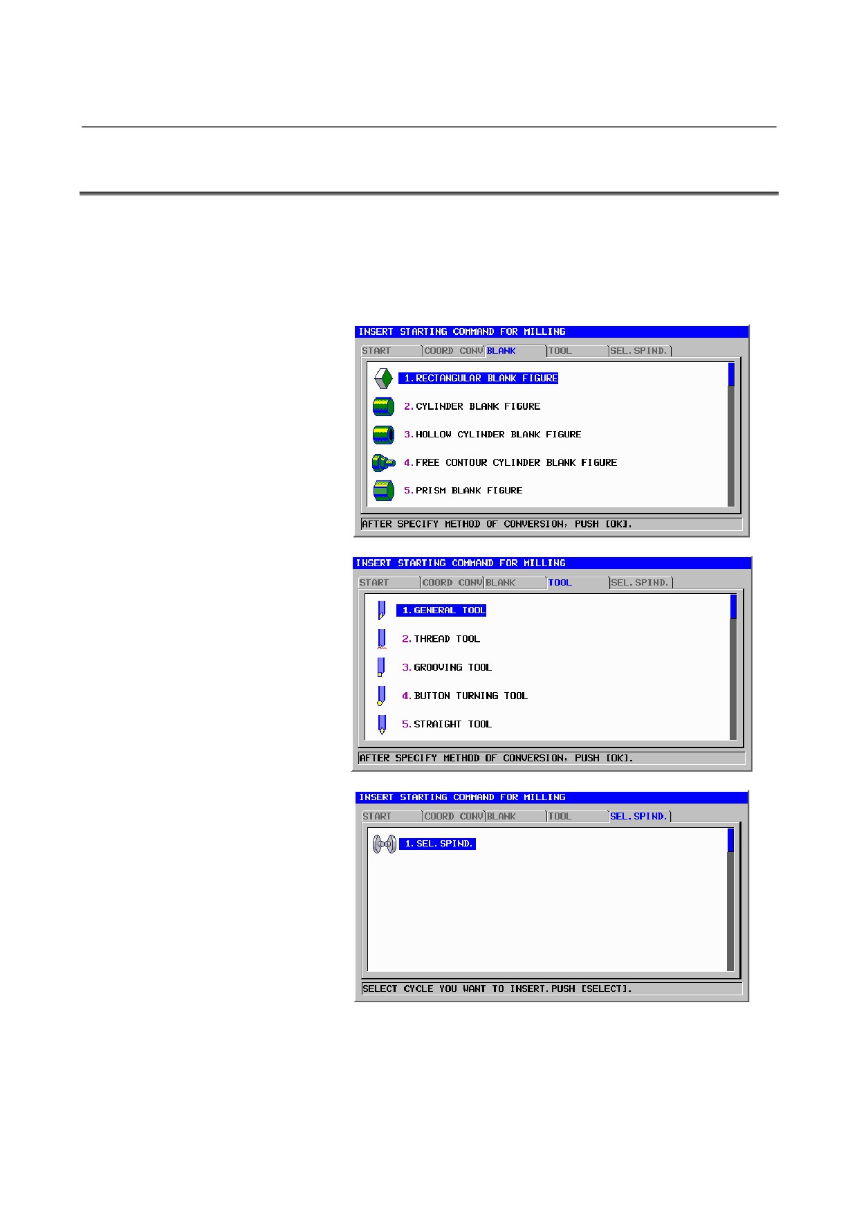
9.MACHINING SIMULATION AND DRAWING DURING MACHINING OPERATION
B-63874EN/05
9.9
SETTING OF DATA FOR ANIMATION
When animation can be performed, a blank figure and tool figure must
be set. Such animation data must be set in the DRAWING
DEFINITION block, which is to be entered in a machining program.
To display the window for entering DRAWING DEFINITION data,
press [START] in the soft key menu for editing machining programs.
- 190 -
B-63874EN/05
OPERATION
9.MACHINING SIMULATION AND DRAWING DURING MACHINING
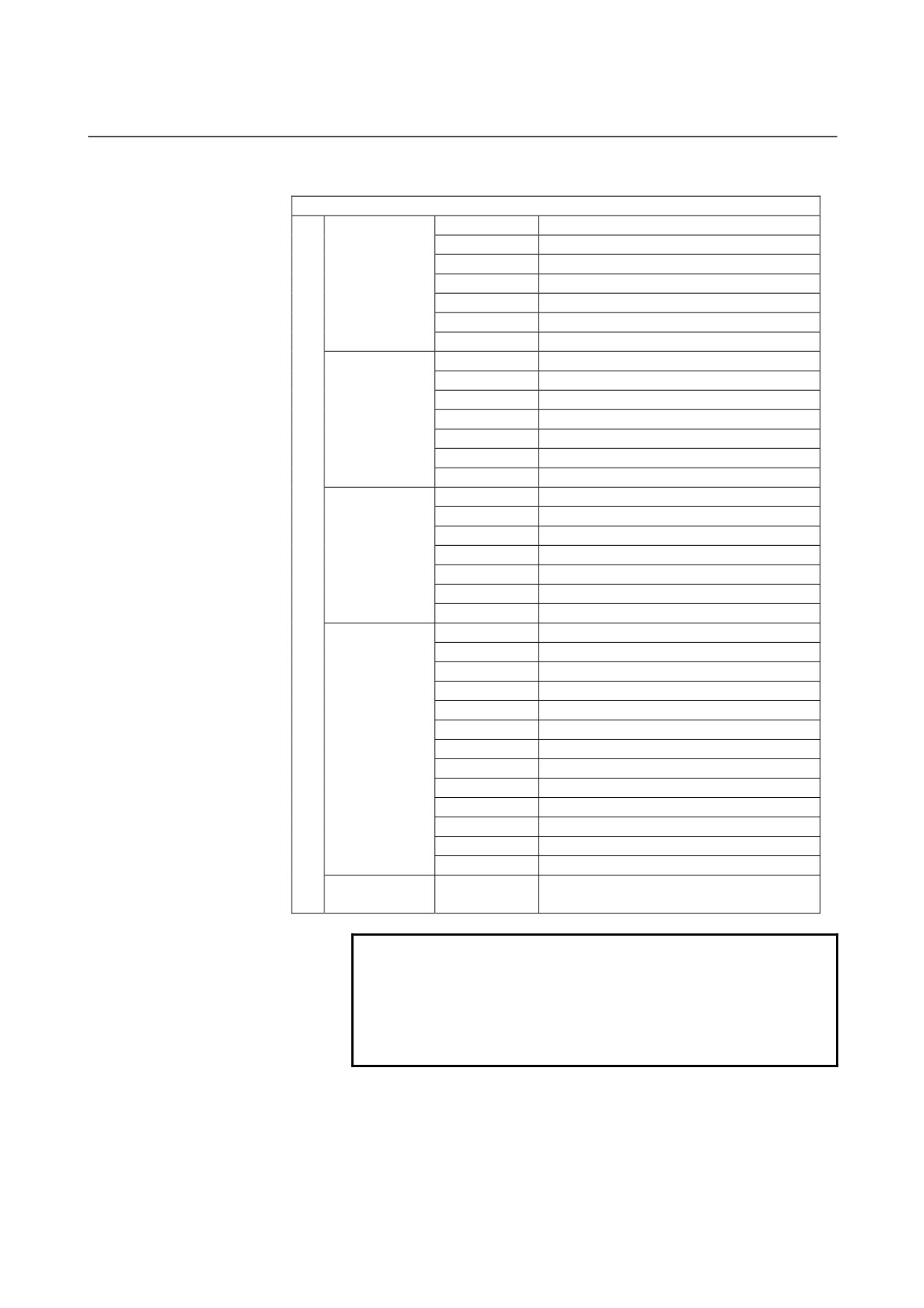
DRAWING DEFINITION
G1902
Rectangular solid
G1900
Column
G1906
Column (around X)
Blank form
G1901
Column with a hole
block
G1907
Column with a hole (around X)
G1903
Prism
G1904
Prism with a hole
G1970
Start point
G1971
Line
G1972
Arc (CW)
Arbitrary blank
G1973
Arc (CCW)
figure block
G1974
Chamfering
G1975
Corner rounding
G1976
End
G1970
Start point
G1971
Line
Arbitrary blank
G1972
Arc (CW)
figure block
G1973
Arc (CCW)
(around X)
G1974
Chamfering
G1975
Corner rounding
G1976
End
G1910
General-purpose tool (turning)
G1911
Threading tool (turning)
G1912
Grooving tool (turning)
G1913
Round-nose tool (turning)
G1914
Point nose straight tool (turning)
G1921
Drill (turning, milling)
Tool definition
G1931
Counter sink tool (milling)
block
G1932
Flat end mill (milling)
G1933
Ball end mill (milling)
G1922
Tap (turning, milling)
G1923
Reamer (turning, milling)
G1924
Boring tool (turning, milling)
G1930
Face mill (milling)
Spindle
G1998
Spindle selection
selection block
NOTE
1 A tool figure during animation is drawn by a tool
definition block.
2 A blank is initialized by a blank figure block.
3 When you use ‘Tool Data Base Function’, you do
not need to specify ‘Tool Definition Block’.
- 191 -