FANUC MANUAL GUIDE i. OPERATOR’S MANUAL - page 5
5.DETAILED DESCRIPTIONS ABOUT ENTERING ARBITRARY FIGURES OPERATION
B-63874EN/05
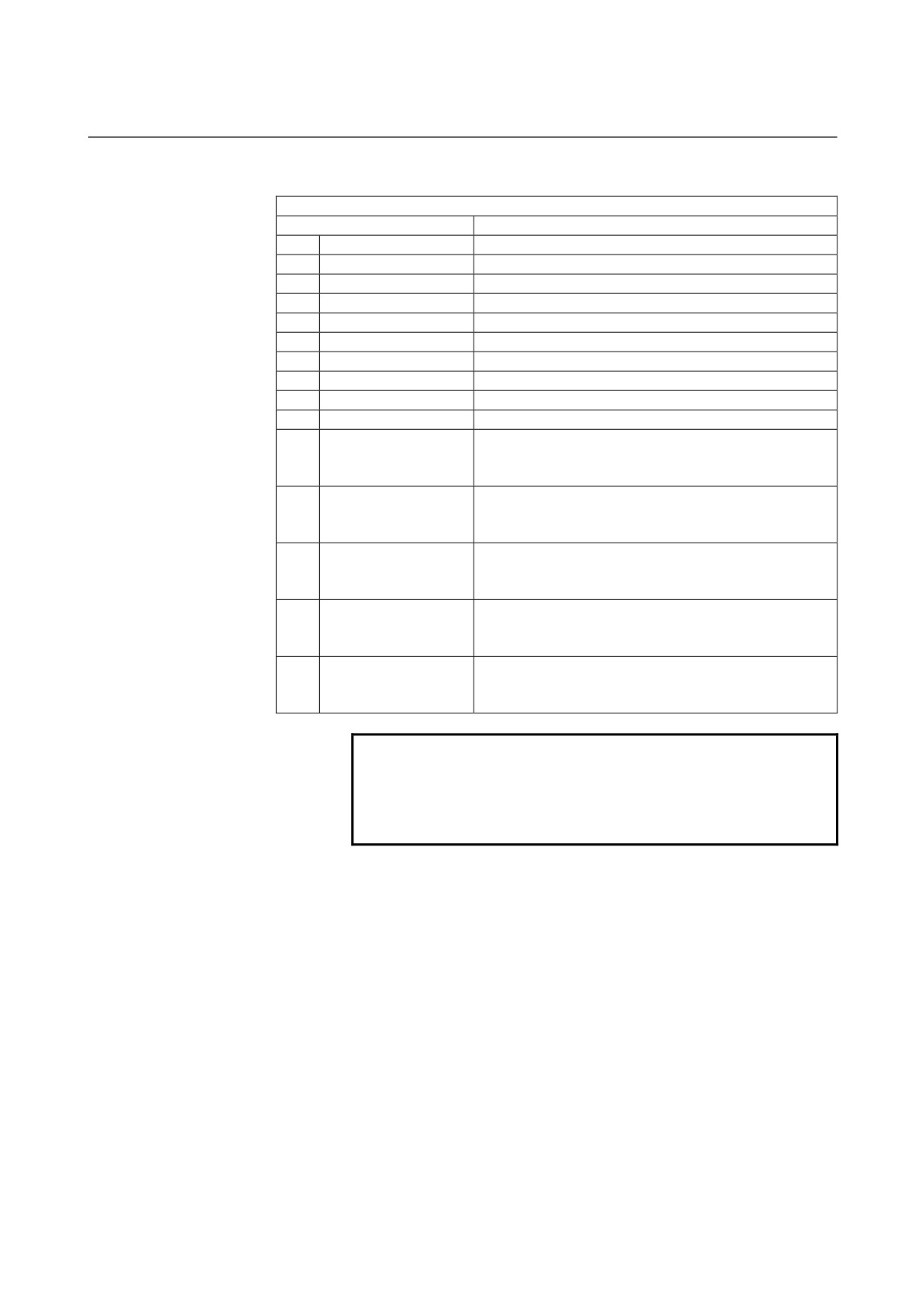
ELEMENT & ATTRIBUTE
(OUTPUT DATA)
(Note 2)
Data item
Meaning
H
END POINT Y
Y coordinate of an arc end point
(calculation result)
V
END POINT Z
Z coordinate of an arc end point
(calculation result)
R
RADIUS
Arc radius
(calculation result)
I
CENTER POINT Y
Y coordinate of an arc center
(calculation result)
J
CENTER POINT Z
Z coordinate of an arc center
(calculation result)
C*
END POINT Y
Y coordinate of an arc end point
(input value)
D*
END POINT Z
Z coordinate of an arc end point
(input value)
E*
RADIUS
Arc radius
(input value)
P*
CENTER POINT CY
Y coordinate of an arc center
(input value)
Q*
CENTER POINT CZ
Z coordinate of an arc center
(input value)
L
LAST CONNECTION
[1] : In contact with the immediately preceding figure
[0] : Not in contact with the immediately preceding figure
(input value)
M
NEXT CONNECTION
[1] : In contact with the immediately preceding figure
[0] : Not in contact with the immediately preceding figure
(input value)
U
ROUTE TYPE
[1] : An arc with a long route is made
[0] : An arc with a short route is made
(input value)
T
ELEMENT TYPE
[1] : Cut as parts
[2] : Cut as a blank portion
(input value)
S
SELECT FIG. INFO.
In the case of plural intersection or contact, the operator
sets a candidate.
(input value)
NOTE
2
‘OUTPUT DATA’ means the items, which are
displayed on the program window as creating
program. It can be referenced only for program
display purposes.
- 102 -
B-63874EN/05
OPERATION 5.DETAILED DESCRIPTIONS ABOUT ENTERING ARBITRARY FIGURES
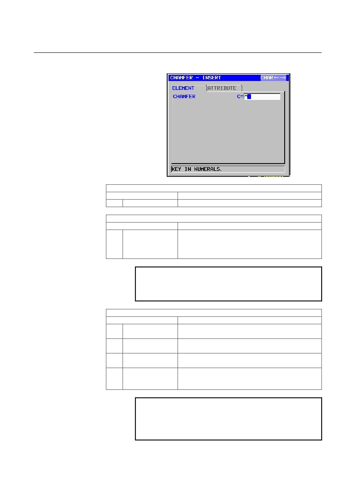
Chamfering: G1304 (YZ plane)
ELEMENT
(INPUT DATA)
(Note 1)
Data item
Meaning
C
CHAMFER
Amount of chamfering (radius value, positive value)
ATTRIBUTE
(INPUT DATA)
(Note 1)
Data item
Meaning
T
ELEMENT TYPE
[PART]
: Cut as parts
[BLANK] : Cut as a blank portion
Remarks) The system sets the last data as an initial
value.
NOTE
1
‘INPUT DATA’ means the items, which are
displayed on the input data window in editing or
altering.
ELEMENT & ATTRIBUTE
(OUTPUT DATA)
(Note 2)
Data item
Meaning
H
END POINT Y
Y coordinate of the end point of a straight line
(calculation result)
V
END POINT Z
Z coordinate of the end point of a straight line
(calculation result)
C
CHAMFER
Amount of chamfering (radius value, positive value)
(input value)
T
ELEMENT TYPE
[1] : Cut as parts
[2] : Cut as a blank portion
(input value)
NOTE
2
‘OUTPUT DATA’ means the items, which are
displayed on the program window as creating
program. It can be referenced only for program
display purposes.
- 103 -
5.DETAILED DESCRIPTIONS ABOUT ENTERING ARBITRARY FIGURES OPERATION
B-63874EN/05
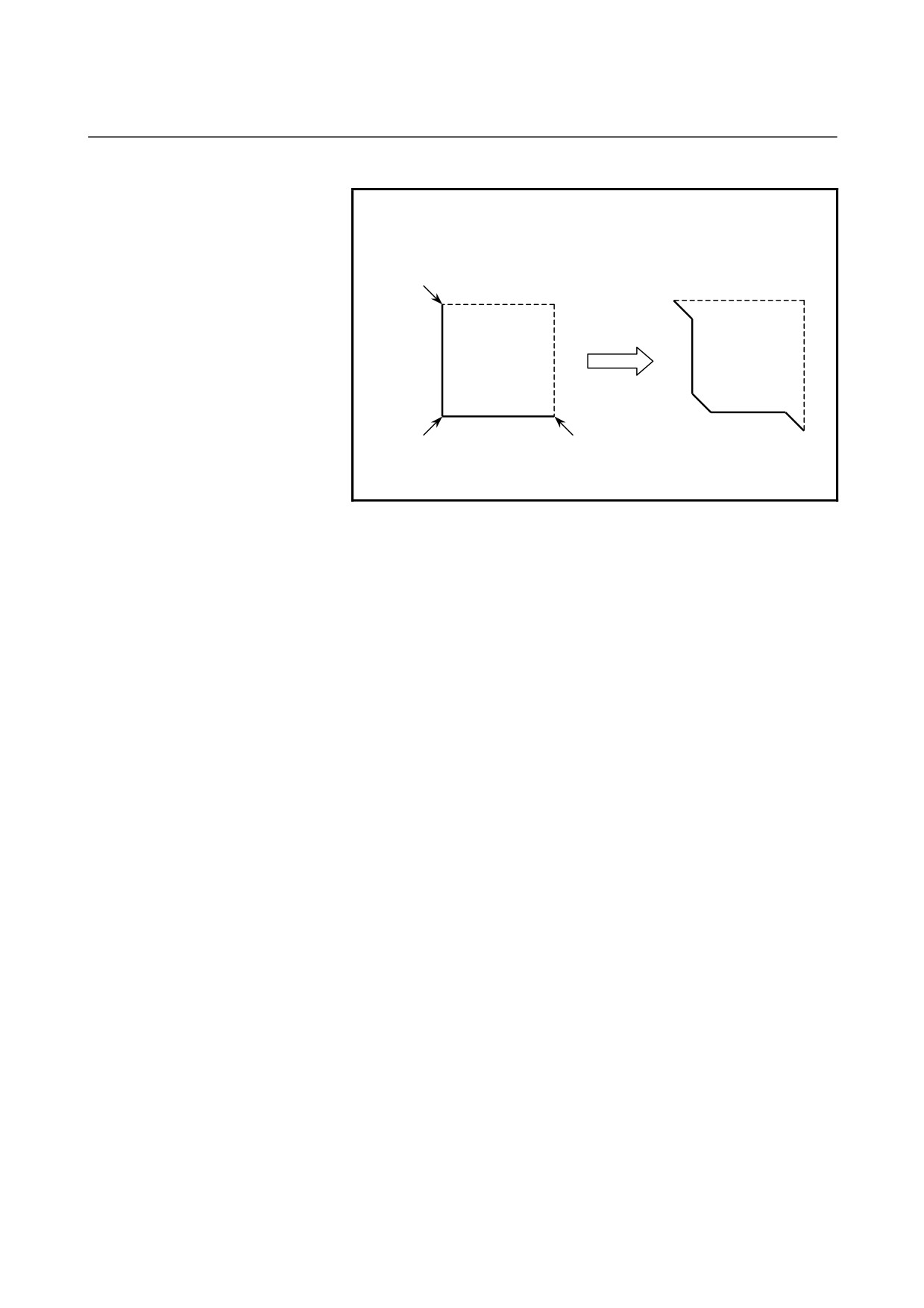
NOTE
3 By setting the parameter No.14851#0=1, Corner
element between a blank element and a part
element can be created in the opposite direction.
C
C
C
C
C
C
Dotted line : blank element
Normal line : part element
- 104 -
B-63874EN/05
OPERATION 5.DETAILED DESCRIPTIONS ABOUT ENTERING ARBITRARY FIGURES
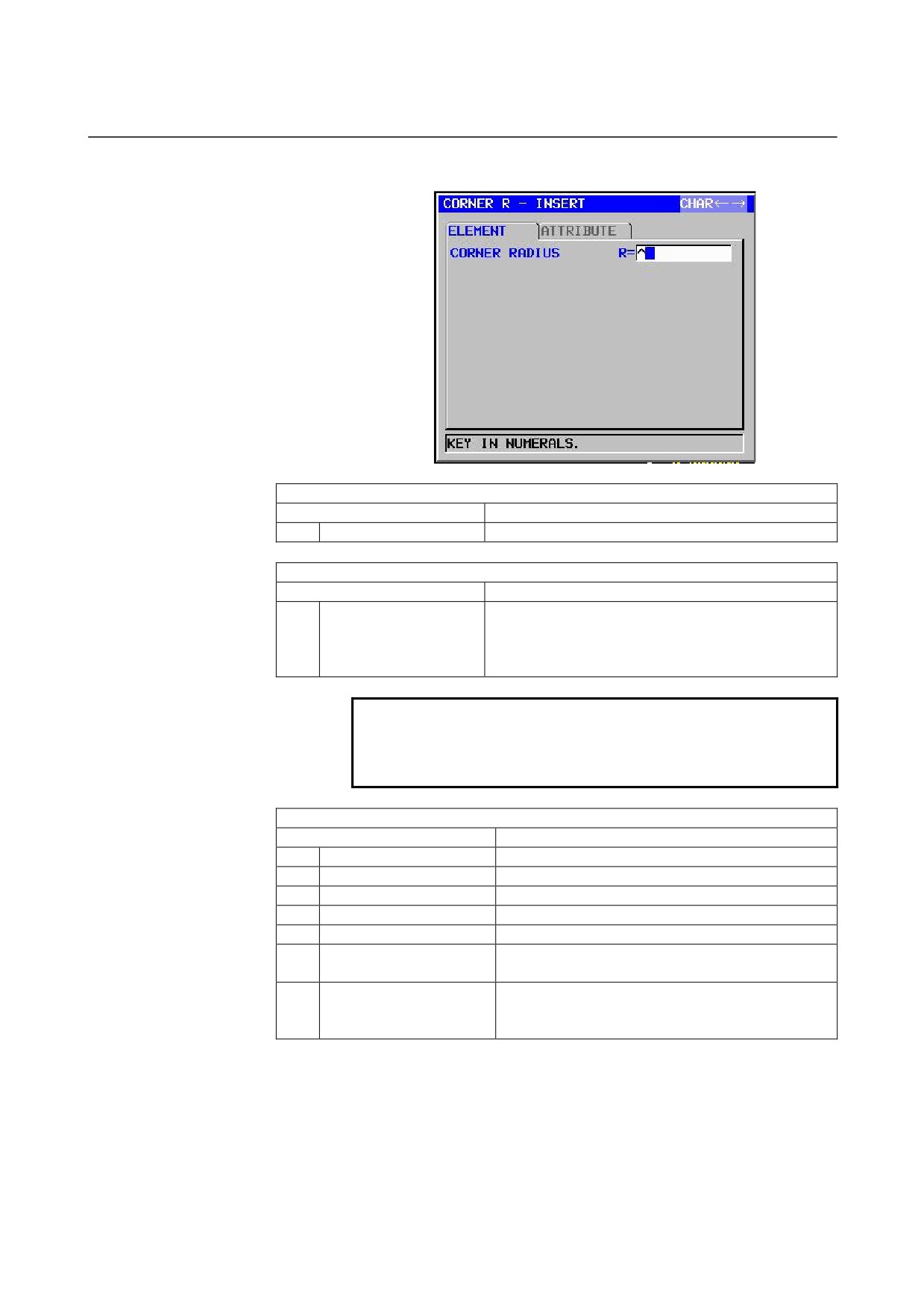
Corner rounding: G1305 (YZ plane)
ELEMENT
(INPUT DATA)
(Note 1)
Data item
Meaning
R
CORNER RADIUS
Corner rounding (radius value, positive value)
ATTRIBUTE
(INPUT DATA)
(Note 1)
Data item
Meaning
T
ELEMENT TYPE
[PART]
: Cut as parts
[BLANK] : Cut as a blank portion
Remarks) The system sets the last data as an initial
value.
NOTE
1
‘INPUT DATA’ means the items, which are
displayed on the input data window in editing or
altering.
ELEMENT & ATTRIBUTE
(OUTPUT DATA)
(Note 2)
Data item
Meaning
H
END POINT Y
Y coordinate of an arc end point (calculation result)
V
END PINT Z
Z coordinate of an arc end point (calculation result)
R
RADIUS
Arc radius
(calculation result)
I
CENTER POINT Y
Y coordinate of an arc center
(calculation result)
J
CENTER POINT Z
Z coordinate of an arc center
(calculation result)
K
ROTATION DIRECTION
[2] : clockwise
[3] : counterclockwise
T
ELEMENT TYPE
[1] : Cut as parts
[2] : Cut as a blank portion
(input value)
- 105 -
5.DETAILED DESCRIPTIONS ABOUT ENTERING ARBITRARY FIGURES OPERATION
B-63874EN/05
NOTE
2
‘OUTPUT DATA’ means the items, which are
displayed on the program window as creating
program. It can be referenced only for program
display purposes.
3 By setting the parameter No.14851#0=1, Corner
element between a blank element and a part
element can be created in the opposite direction.
End of arbitrary figures: G1306 (YZ plane)
This block is output at the end of a series of arbitrary-figure blocks.
NOTE
A series of arbitrary figures must be enclosed
between G1300 (start point) and G1306 (end of
arbitrary figures).
- 106 -
B-63874EN/05
OPERATION 5.DETAILED DESCRIPTIONS ABOUT ENTERING ARBITRARY FIGURES
5.3
ARBITRARY FIGURES FOR THE POLAR COORDINATE
INTERPOLATION PLANE (XC PLANE)
The following types of milling can be specified also for the polar
coordinate interpolation plane (XC plane), and arbitrary figures in the
XC plane can be used in these milling types.
1. Facing
2. Contouring (Side cutting)
3. Pocketing
4. Grooving
5. Emboss machining
NOTE
1 See Chapter 1, "Milling," in Part III for detailed
descriptions about data to be entered for each type
of cycle machining.
2 X coordinate values specified for the XC plane
must also be diameters.
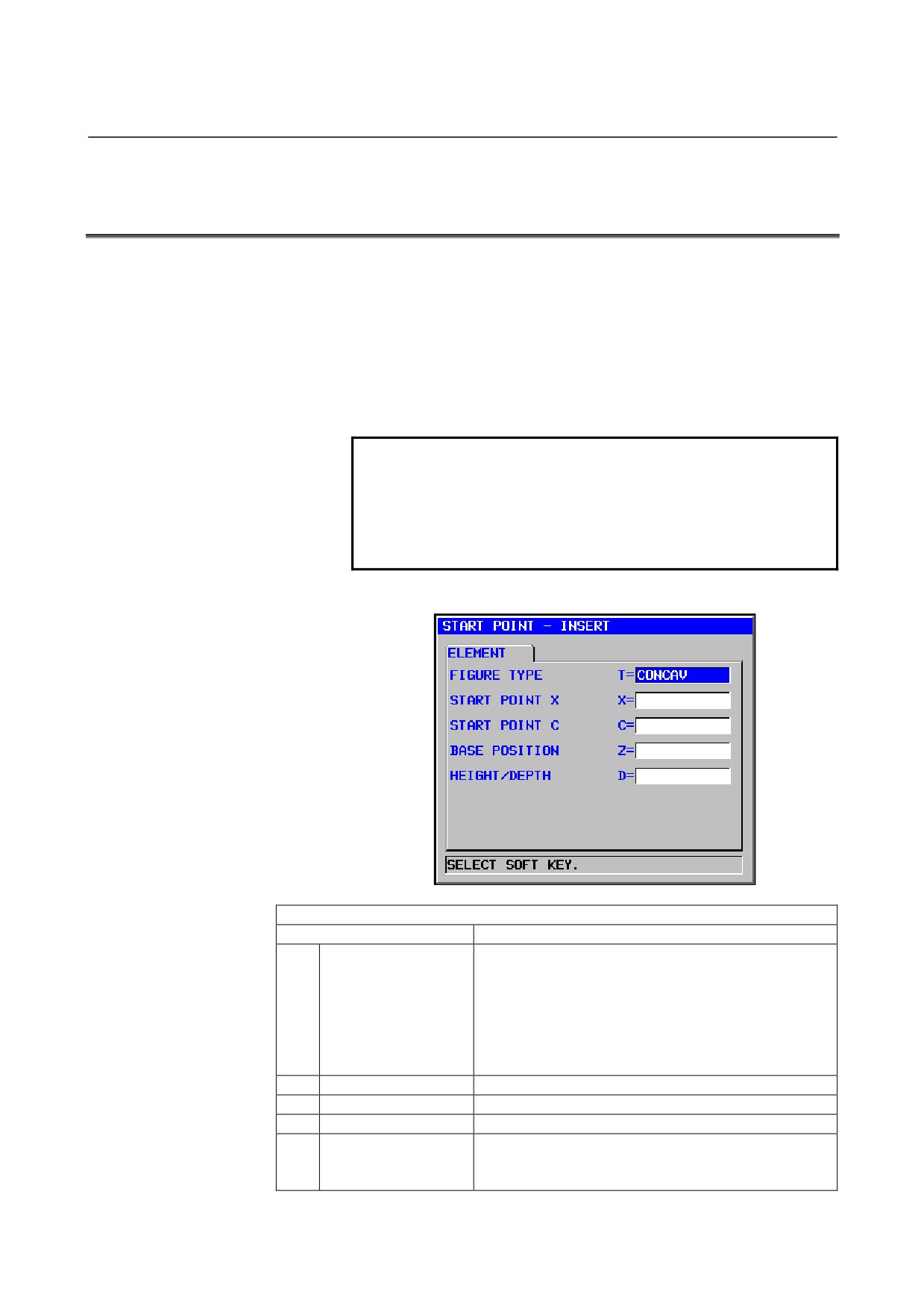
Start point: G1500 (XC plane)
ELEMENT
(INPUT DATA)
(Note 1)
Data item
Meaning
T
FIGURE ATTRIBUTE
[FACE]
: Used as a figure in facing
(Note 2)
[CONVEX] : Used as an outer-perimeter figure in
contouring
[CONCAV] : Used as an inner-perimeter figure in
contouring and emboss machining or a
figure in pocketing
[GROOVE] : Used as a figure in grooving
X
START POINT X
X coordinate of the start point of an arbitrary figure
C
START POINT C
C coordinate of the start point of an arbitrary figure
Z
BASE POSITION
Position of the machining surface of an arbitrary figure
D
HEIGHT/DEPTH
Height or Depth from Base position to cutting surface
Remarks) This item is displayed in Contouring,
Pocketing, Grooving and Emboss machining.
- 107 -
5.DETAILED DESCRIPTIONS ABOUT ENTERING ARBITRARY FIGURES OPERATION
B-63874EN/05
ELEMENT
(INPUT DATA)
(Note 1)
Data item
Meaning
W
GROOVE WIDTH
Groove width (Positive value)
Remarks) This item is displayed in Grooving.
P
FIGURE ATTRIBUTE
[RIGHT] : The right side of an entered figure as cutting
[LEFT]
: The left side of an entered figure as cutting
Remarks) This item is displayed in Open figure of
Contouring.
F
FACE POSITION
[+FACE] : References the figure (+end face)
[-FACE] : References the figure (-end face)
Remarks) This item is displayed when the parameter
No.27000#4=1.
Y
ROTATION AXIS
[C] : The rotation axis is the C axis.
NAME
[A] : The rotation axis is the A axis (No.27000#1=1)
[B] : The rotation axis is the B axis (No.27000#2=1)
[E] : The rotation axis is the E axis (No.27000#3=1)
Remarks) This item is displayed when the parameter
No.27000#0=1.
NOTE
1
‘INPUT DATA’ means the items, which are
displayed on the input data window in editing or
altering.
2 Select, with a figure type for a start point, which
milling operation is to use an arbitrary figure. Data
to be entered for the start point varies depending
on what figure type is selected. For details, see
descriptions about the respective milling types.
ELEMENT
(OUTPUT DATA)
(Note 3)
Data item
Meaning
T
FIGURE ATTRIBUTE
[1] : Used as a figure in facing
[2] : Used as an outer-perimeter figure in contouring
[3] : Used as an inner-perimeter figure in contouring and
emboss machining or a figure in pocketing
[4] : Used as a figure in grooving
(input value)
H
START POINT X
X coordinate of the start point
(input value)
V
START POINT C
C coordinate of the start point
(input value)
B
BASE POSITION
Position of the machining surface
(input value)
L
HEIGHT/DEPTH
Height or Depth from Base position to cutting surface
(input value)
Remarks) This item is displayed in Contouring,
Pocketing, Grooving and Emboss machining.
D
GROOVE WIDTH
Groove width (Positive value)
(input value)
Remarks) This item is displayed in Grooving.
P
FIGURE ATTRIBUTE
[1] : The right side of an entered figure as cutting
[2] : The left side of an entered figure as cutting
Remarks) This item is displayed in Open figure of
Contouring.
(input value)
- 108 -
B-63874EN/05
OPERATION 5.DETAILED DESCRIPTIONS ABOUT ENTERING ARBITRARY FIGURES
ELEMENT
(OUTPUT DATA)
(Note 3)
Data item
Meaning
Y
ROTATION AXIS
[1] : The rotation axis is the C axis.
NAME
[2] : The rotation axis is the A axis (No.27000#1=1)
[3] : The rotation axis is the B axis (No.27000#2=1)
[4] : The rotation axis is the E axis (No.27000#3=1)
(input value)
Z
FACE POSITION
[1] : References the figure (+end face)
[2] : References the figure (-end face)
(input value)
NOTE
3
‘OUTPUT DATA’ means the items, which are
displayed on the program window as creating
program. It can be referenced only for program
display purposes.
- 109 -
5.DETAILED DESCRIPTIONS ABOUT ENTERING ARBITRARY FIGURES OPERATION
B-63874EN/05
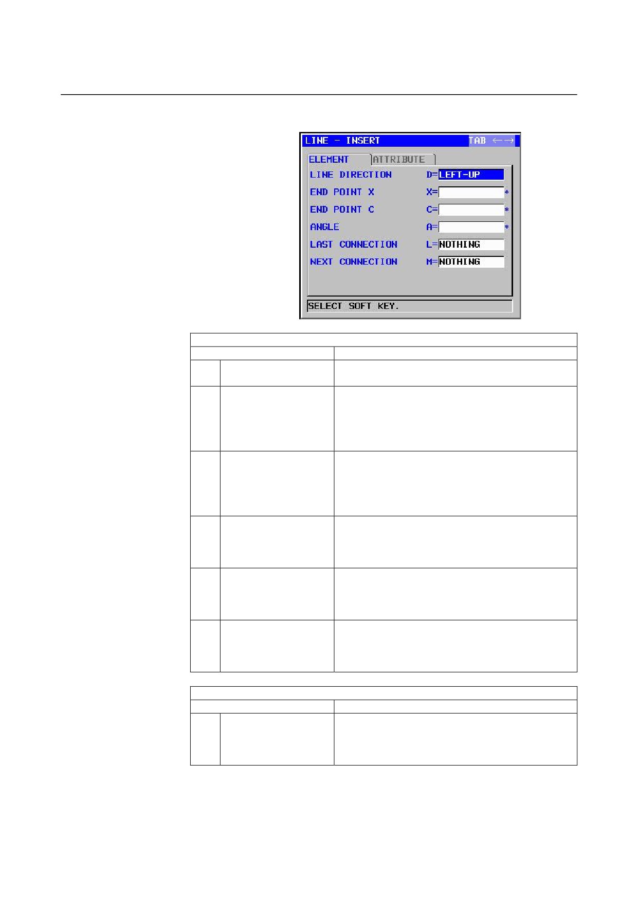
Straight line: G1501 (XC plane)
ELEMENT
(INPUT DATA)
(Note 1)
Data item
Meaning
D
LINE DIRECTION
The direction of a straight line is selected from a menu
indicated on a soft key.
X*
END POINT X
X coordinate of the end point of a straight line
Remarks1) This data may not be displayed depending
on the value entered as the direction of the
straight line.
Remarks2) Incremental programming is possible.
C*
END POINT C
C coordinate of the end point of a straight line
Remarks1) This data may not be displayed depending
on the value entered as the direction of the
straight line.
Remarks2) Incremental programming is possible.
A*
ANGLE
Straight-line angle
Remarks) This data may not be displayed depending
on the value entered as the direction of the
straight line.
L
LAST CONNECTION
[TANGNT] : In contact with the immediately
preceding figure
[NO SET]
: Not in contact with the immediately
preceding figure (initial value)
M
NEXT CONNECTION
[TANGNT] : In contact with the immediately following
figure
[NO SET]
: Not in contact with the immediately
following figure (initial value)
ATTRIBUTE
(INPUT DATA)
(Note 1)
Data item
Meaning
T
ELEMENT TYPE
[PART]
: Cut as parts
[BLANK] : Cut as a blank portion
Remarks) The system sets the last data as an initial
value.
- 110 -
B-63874EN/05
OPERATION 5.DETAILED DESCRIPTIONS ABOUT ENTERING ARBITRARY FIGURES
NOTE
1
‘INPUT DATA’ means the items, which are
displayed on the input data window in editing or
altering.
ELEMENT & ATTRIBUTE
(OUTPUT DATA)
(Note 2)
Data item
Meaning
H
END POINT X
X coordinate of the end point of a straight line
(calculation result)
V
END POINT C
C coordinate of the end point of a straight line
(calculation result)
K
LINE DIRECTION
The direction of a straight line is selected from a menu
indicated on a soft key.
(input value)
C*
END POINT X
X coordinate of the end point of a straight line
(input value)
D*
END POINT C
C coordinate of the end point of a straight line
(input value)
A*
ANGLE
Straight-line angle
(input value)
L
LAST CONNECTION
[1] : In contact with the immediately preceding figure
[0] : Not in contact with the immediately preceding figure
(input value)
M
NEXT CONNECTION
[1] : In contact with the immediately following figure
[0] : Not in contact with the immediately following figure
(input value)
T
ELEMENT TYPE
[1] : Cut as parts
[2] : Cut as a blank portion
(input value)
S
SELECT FIG. INFO.
In the case of plural intersection or contact, the operator
sets a candidate.
(input value)
NOTE
2
‘OUTPUT DATA’ means the items, which are
displayed on the program window as creating
program. It can be referenced only for program
display purposes.
- 111 -
5.DETAILED DESCRIPTIONS ABOUT ENTERING ARBITRARY FIGURES OPERATION
B-63874EN/05
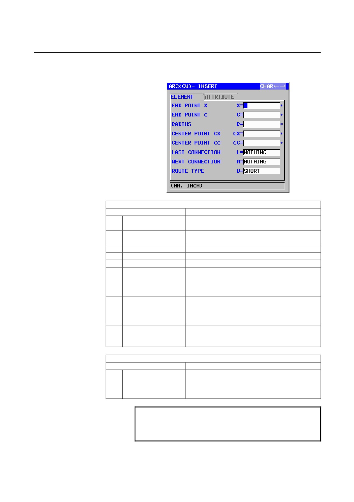
Arc (CW): G1502 (XC plane)
Arc (CCW): G1503 (XC plane)
ELEMENT
(INPUT DATA)
(Note 1)
Data item
Meaning
X*
END POINT X
X coordinate of an arc end point
Remarks) Incremental programming is possible.
C*
END POINT C
C coordinate of an arc end point
Remarks) Incremental programming is possible.
R*
RADIUS
Arc radius
CX*
CENTER POINT CX
X coordinate of an arc center
CC*
CENTER POINT CC
C coordinate of an arc center
L
LAST CONNECTION
[TANGNT] : In contact with the immediately preceding
figure
[NO SET]
: Not in contact with the immediately
preceding figure (initial value)
M
NEXT CONNECTION
[TANGNT] : In contact with the immediately preceding
figure
[NO SET]
: Not in contact with the immediately
preceding figure (initial value)
U
ROUTE TYPE
[LONG]
: An arc with a long route is made
[SHORT]
: An arc with a short route is made
(initial value)
ATTRIBUTE
(INPUT DATA)
(Note 1)
Data item
Meaning
T
ELEMENT TYPE
[PART]
: Cut as parts
[BLANK] : Cut as a blank portion
Remarks) The system sets the last data as an initial
value.
NOTE
1
‘INPUT DATA’ means the items, which are
displayed on the input data window in editing or
altering.
- 112 -
B-63874EN/05
OPERATION 5.DETAILED DESCRIPTIONS ABOUT ENTERING ARBITRARY FIGURES
ELEMENT & ATTRIBUTE
(OUTPUT DATA)
(Note 2)
Data item
Meaning
H
END POINT X
X coordinate of an arc end point
(calculation result)
V
END POINT C
C coordinate of an arc end point
(calculation result)
R
RADIUS
Arc radius
(calculation result)
I
CENTER POINT X
X coordinate of an arc center
(calculation result)
J
CENTER POINT C
C coordinate of an arc center
(calculation result)
C*
END POINT X
X coordinate of an arc end point
(input value)
D*
END POINT C
C coordinate of an arc end point
(input value)
E*
RADIUS
Arc radius
(input value)
P*
CENTER POINT CX
X coordinate of an arc center
(input value)
Q*
CENTER POINT CC
C coordinate of an arc center
(input value)
L
LAST CONNECTION
[1] : In contact with the immediately preceding figure
[0] : Not in contact with the immediately preceding figure
(input value)
M
NEXT CONNECTION
[1] : In contact with the immediately preceding figure
[0] : Not in contact with the immediately preceding figure
(input value)
U
ROUTE TYPE
[1] : An arc with a long route is made
[0] : An arc with a short route is made
(input value)
T
ELEMENT TYPE
[1] : Cut as parts
[2] : Cut as a blank portion
(input value)
S
SELECT FIG. INFO.
In the case of plural intersection or contact, the operator
sets a candidate.
(input value)
NOTE
2
‘OUTPUT DATA’ means the items, which are
displayed on the program window as creating
program. It can be referenced only for program
display purposes.
- 113 -
5.DETAILED DESCRIPTIONS ABOUT ENTERING ARBITRARY FIGURES OPERATION
B-63874EN/05
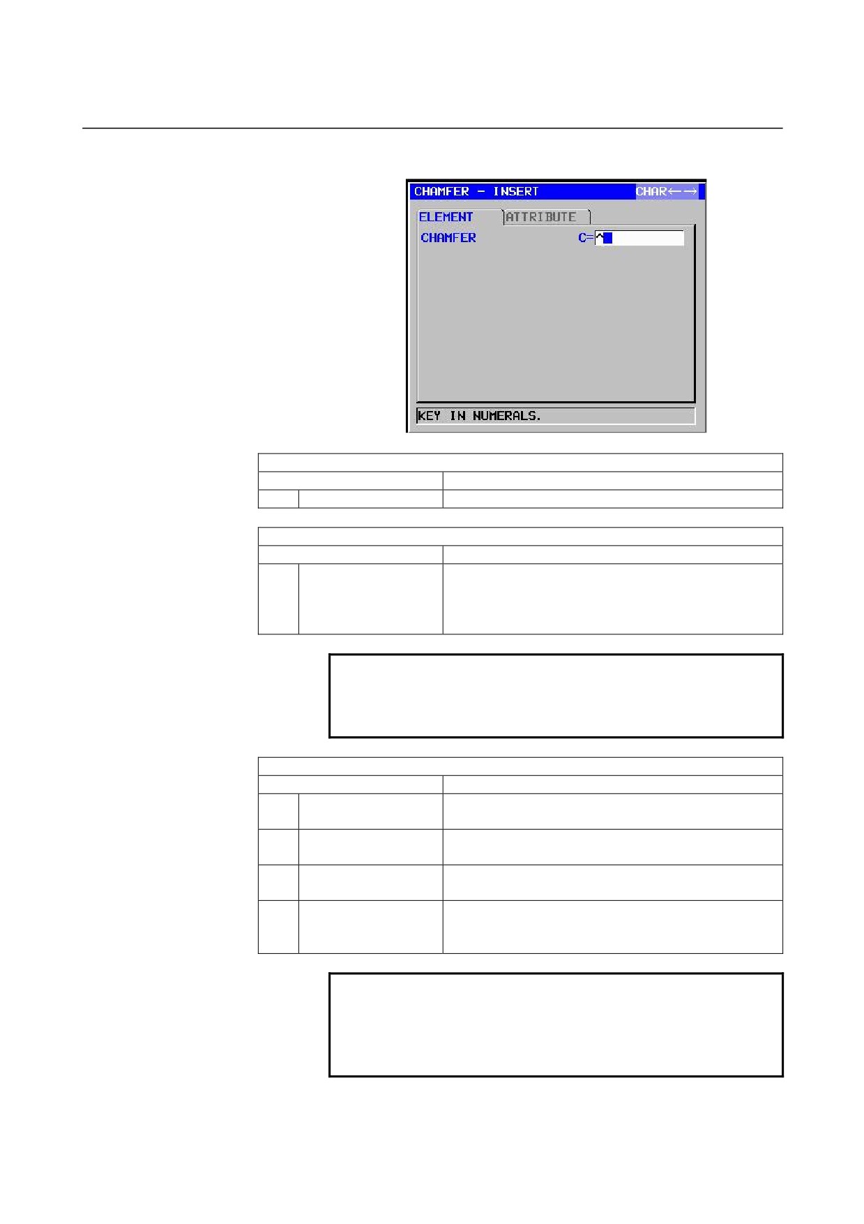
Chamfering: G1504 (XC plane)
ELEMENT
(INPUT DATA)
(Note 1)
Data item
Meaning
C
CHAMFER
Amount of chamfering (radius value, positive value)
ATTRIBUTE
(INPUT DATA)
(Note 1)
Data item
Meaning
T
ELEMENT TYPE
[PART]
: Cut as parts
[BLANK] : Cut as a blank portion
Remarks) The system sets the last data as an initial
value.
NOTE
1
‘INPUT DATA’ means the items, which are
displayed on the input data window in editing or
altering.
ELEMENT & ATTRIBUTE
(OUTPUT DATA)
(Note 2)
Data item
Meaning
H
END POINT X
X coordinate of the end point of a straight line
(calculation result)
V
END POINT C
C coordinate of the end point of a straight line
(calculation result)
C
CHAMFER
Amount of chamfering (radius value, positive value)
(input value)
T
ELEMENT TYPE
[1] : Cut as parts
[2] : Cut as a blank portion
(input value)
NOTE
2
‘OUTPUT DATA’ means the items, which are
displayed on the program window as creating
program. It can be referenced only for program
display purposes.
- 114 -
B-63874EN/05
OPERATION 5.DETAILED DESCRIPTIONS ABOUT ENTERING ARBITRARY FIGURES
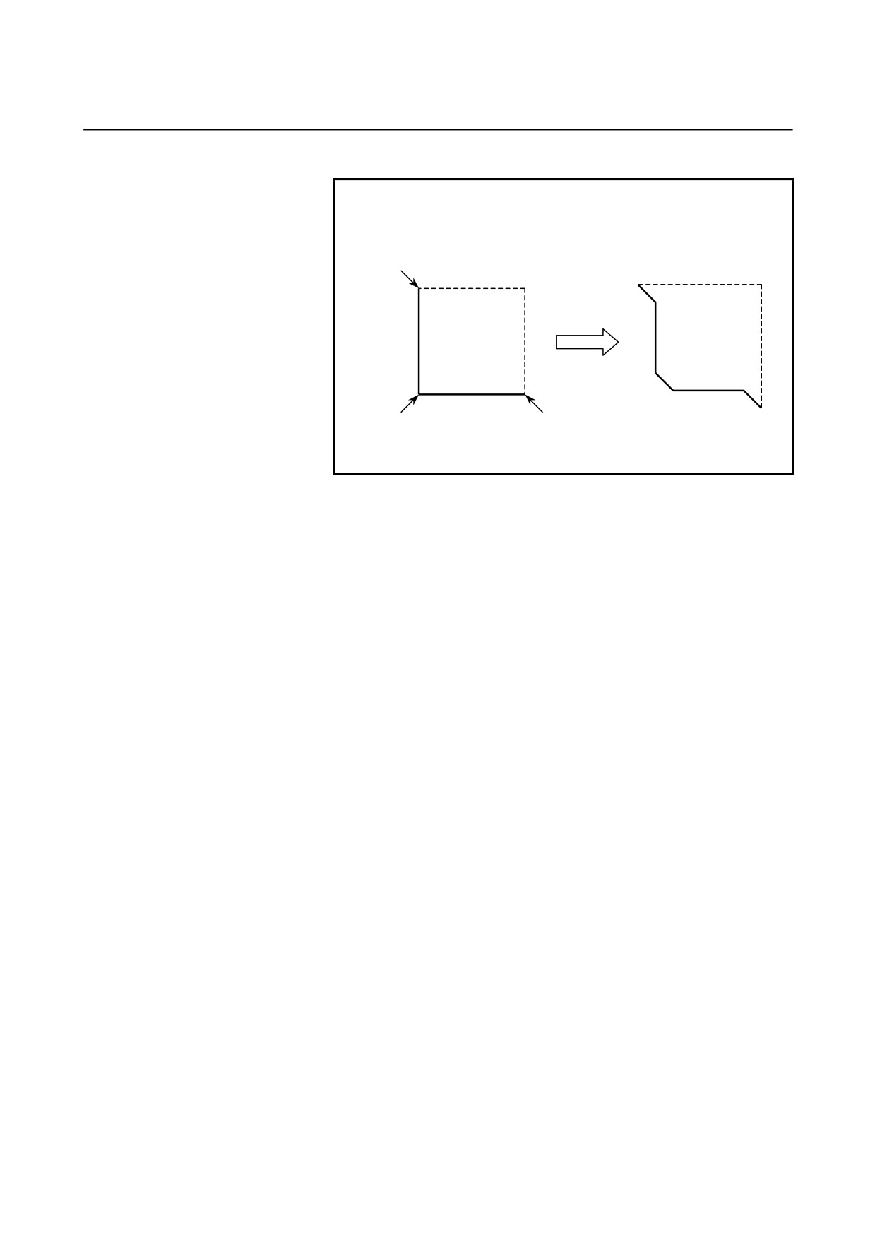
NOTE
3 By setting the parameter No.14851#0=1, Corner
element between a blank element and a part
element can be created in the opposite direction.
C
C
C
C
C
C
Dotted line : blank element
Normal line : part element
- 115 -
5.DETAILED DESCRIPTIONS ABOUT ENTERING ARBITRARY FIGURES OPERATION
B-63874EN/05
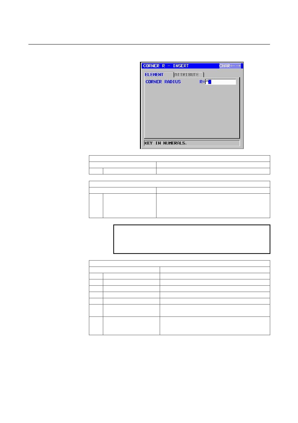
Corner rounding: G1505 (XC plane)
ELEMENT
(INPUT DATA)
(Note 1)
Data item
Meaning
R
CORNER RADIUS
Corner rounding (radius value, positive value)
ATTRIBUTE
(INPUT DATA)
(Note 1)
Data item
Meaning
T
ELEMENT TYPE
[PART]
: Cut as parts
[BLANK] : Cut as a blank portion
Remarks) The system sets the last data as an initial
value.
NOTE
1
‘INPUT DATA’ means the items, which are
displayed on the input data window in editing or
altering.
ELEMENT & ATTRIBUTE
(OUTPUT DATA)
(Note 2)
Data item
Meaning
H
END POINT X
X coordinate of an arc end point (calculation result)
V
END POINT C
C coordinate of an arc end point (calculation result)
R
RADIUS
Arc radius
(calculation result)
I
CENTER POINT X
X coordinate of an arc center
(calculation result)
J
CENTER POINT C
C coordinate of an arc center
(calculation result)
K
ROTATION DIRECTION
[2] : clockwise
[3] : counterclockwise
T
ELEMENT TYPE
[1] : Cut as parts
[2] : Cut as a blank portion
(input value)
- 116 -
B-63874EN/05
OPERATION 5.DETAILED DESCRIPTIONS ABOUT ENTERING ARBITRARY FIGURES
NOTE
2
‘OUTPUT DATA’ means the items, which are
displayed on the program window as creating
program. It can be referenced only for program
display purposes.
3 By setting the parameter No.14851#0=1, Corner
element between a blank element and a part
element can be created in the opposite direction.
End of arbitrary figures: G1506 (XC plane)
This block is output at the end of a series of arbitrary-figure blocks.
NOTE
A series of arbitrary figures must be enclosed
between G1500 (start point) and G1506 (end of
arbitrary figures).
- 117 -
5.DETAILED DESCRIPTIONS ABOUT ENTERING ARBITRARY FIGURES OPERATION
B-63874EN/05
5.4
ARBITRARY FIGURES FOR THE CYLINDRICAL
SURFACE (ZC PLANE)
The following types of milling can be specified also for the cylindrical
surface (ZC plane), and arbitrary figures in the ZC plane can be used
in these milling types.
1. Facing
2. Contouring (Side cutting)
3. Pocketing
4. Grooving
5. Emboss machining
NOTE
See Chapter 1, "Milling," in Part III for detailed
descriptions about data to be entered for each type
of cycle machining.
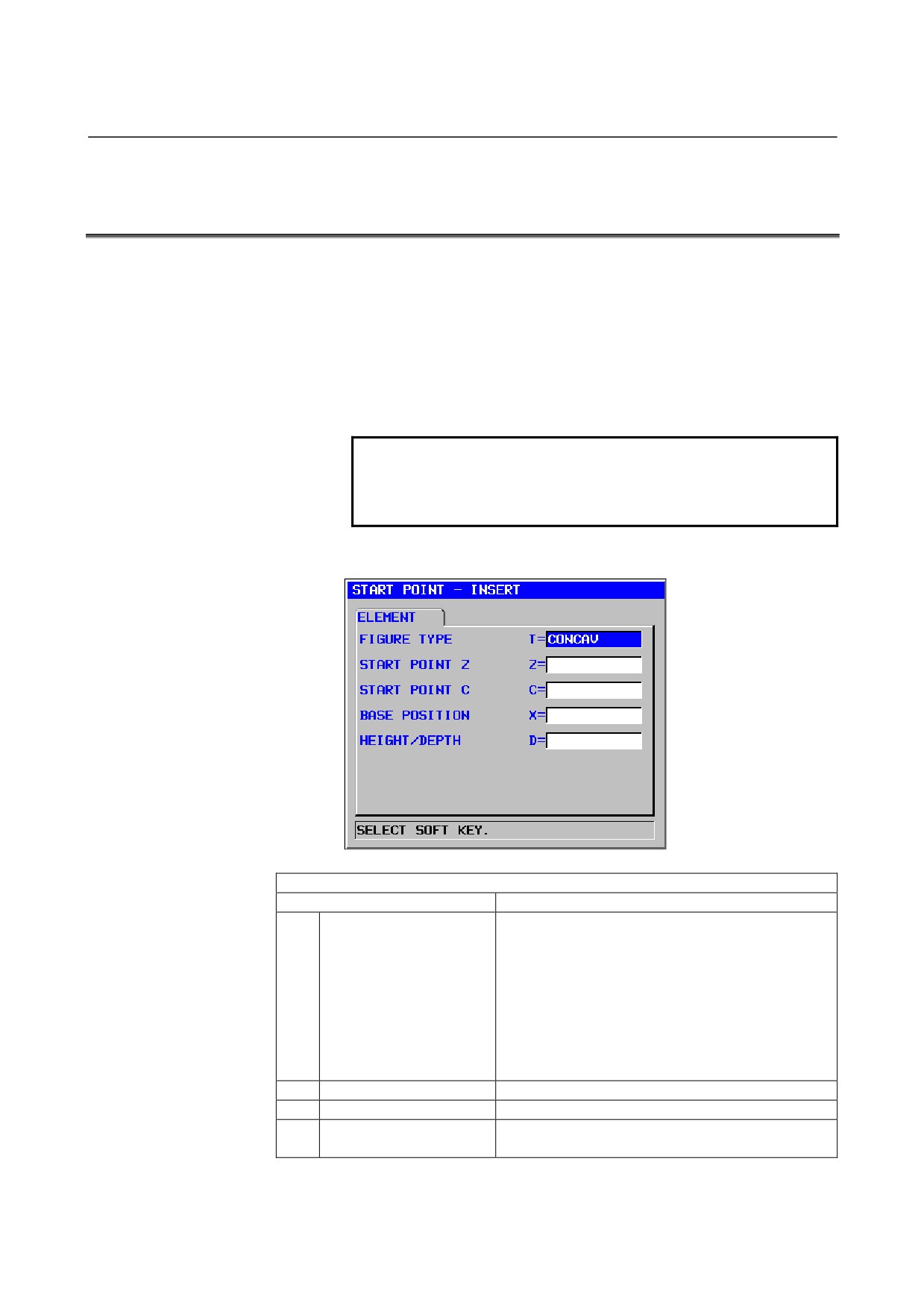
Start point: G1600 (ZC plane)
ELEMENT
(INPUT DATA)
(Note 1)
Data item
Meaning
T
FIGURE ATTRIBUTE
[FACE]
: Used as a figure in facing
(Note 2)
[CONVEX] : Used as an outer-perimeter figure in
contouring
[CONCAV] : Used as an inner-perimeter figure in
contouring and emboss machining or a
figure in pocketing
[GROOVE] : Used as a figure in grooving
Remarks) Be sure to select [FACE] if facing is
selected.
Z
START POINT Z
Z coordinate of the start point of an arbitrary figure
C
START POINT C
C coordinate of the start point of an arbitrary figure
X
BASE POSITION
Position of the machining surface of an arbitrary
figure
- 118 -
B-63874EN/05
OPERATION 5.DETAILED DESCRIPTIONS ABOUT ENTERING ARBITRARY FIGURES
ELEMENT
(INPUT DATA)
(Note 1)
Data item
Meaning
D
HEIGHT/DEPTH
Height or Depth from Base position to cutting surface
Remarks) This item is displayed in Contouring,
Pocketing, Grooving and Emboss
machining.
W
GROOVE WIDTH
Groove width (Positive value)
Remarks) This item is displayed in Grooving.
P
FIGURE ATTRIBUTE
[RIGHT] : The right side of an entered figure as
cutting
[LEFT]
: The left side of an entered figure as cutting
Remarks) This item is displayed in Open figure of
Contouring.
Y
ROTATION AXIS NAME
[C] : The rotation axis is the C axis.
[A] : The rotation axis is the A axis (No.27000#1=1)
[B] : The rotation axis is the B axis (No.27000#2=1)
[E] : The rotation axis is the E axis (No.27000#3=1)
Remarks) This item is displayed when the parameter
No.27000#0=1.
NOTE
1
‘INPUT DATA’ means the items, which are
displayed on the input data window in editing or
altering.
2 Select, with a figure type for a start point, which
milling operation is to use an arbitrary figure. Data
to be entered for the start point varies depending
on what figure type is selected. For details, see
descriptions about the respective milling types.
ELEMENT
(OUTPUT DATA)
(Note 3)
Data item
Meaning
T
FIGURE ATTRIBUTE
[1] : Used as a figure in facing
[2] : Used as an outer-perimeter figure in contouring
[3] : Used as an inner-perimeter figure in contouring and
emboss machining or a figure in pocketing
[4] : Used as a figure in grooving
(input value)
H
START POINT Z
Z coordinate of the start point
(input value)
V
START POINT C
C coordinate of the start point
(input value)
I
START POINT (Z
Z coordinate of an arc end point
(calculation result)
AXIS)
J
START POINT (C
C coordinate of an arc end point
(calculation result)
AXIS)
B
BASE POSITION
Position of the machining surface
(input value)
L
HEIGHT/DEPTH
Height or Depth from Base position to cutting surface
Remarks) This item is displayed in Contouring,
Pocketing, Grooving and Emboss machining.
(input value)
D
GROOVE WIDTH
Groove width (Positive value)
Remarks) This item is displayed in Grooving.
(input value)
- 119 -
5.DETAILED DESCRIPTIONS ABOUT ENTERING ARBITRARY FIGURES OPERATION
B-63874EN/05
ELEMENT
(OUTPUT DATA)
(Note 3)
Data item
Meaning
P
FIGURE ATTRIBUTE
[1] : The right side of an entered figure as cutting
[2] : The left side of an entered figure as cutting
Remarks) This item is displayed in Open figure of
Contouring.
(input value)
Y
FACE POSITION
[1] : The rotation axis is the C axis.
[2] : The rotation axis is the A axis (No.27001#1=1)
[3] : The rotation axis is the B axis (No.27001#2=1)
[4] : The rotation axis is the E axis (No.27001#3=1)
(input value)
NOTE
3
‘OUTPUT DATA’ means the items, which are
displayed on the program window as creating
program. It can be referenced only for program
display purposes.
- 120 -
B-63874EN/05
OPERATION 5.DETAILED DESCRIPTIONS ABOUT ENTERING ARBITRARY FIGURES
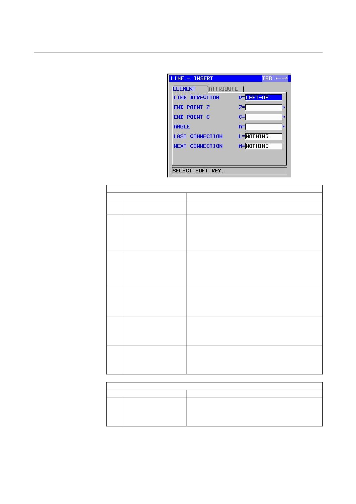
Straight line: G1601 (ZC plane)
ELEMENT
(INPUT DATA)
(Note 1)
Data item
Meaning
D
LINE DIRECTION
The direction of a straight line is selected from a menu
indicated on a soft key.
Z*
END POINT Z
Z coordinate of the end point of a straight line
Remarks1) This data may not be displayed depending
on the value entered as the direction of the
straight line.
Remarks2) Incremental programming is possible.
C*
END POINT C
C coordinate of the end point of a straight line
Remarks1) This data may not be displayed depending
on the value entered as the direction of the
straight line.
Remarks2) Incremental programming is possible.
A*
ANGLE
Straight-line angle
Remarks) This data may not be displayed depending
on the value entered as the direction of the
straight line.
L
LAST CONNECTION
[TANGNT] : In contact with the immediately
preceding figure
[NO SET]
: Not in contact with the immediately
preceding figure (initial value)
M
NEXT CONNECTION
[TANGNT] : In contact with the immediately following
figure
[NO SET]
: Not in contact with the immediately
following figure (initial value)
ATTRIBUTE
(INPUT DATA)
(Note 1)
Data item
Meaning
T
ELEMENT TYPE
[PART]
: Cut as parts
[BLANK] : Cut as a blank portion
Remarks) The system sets the last data as an initial
value.
- 121 -
5.DETAILED DESCRIPTIONS ABOUT ENTERING ARBITRARY FIGURES OPERATION
B-63874EN/05
NOTE
1
‘INPUT DATA’ means the items, which are
displayed on the input data window in editing or
altering.
ELEMENT & ATTRIBUTE
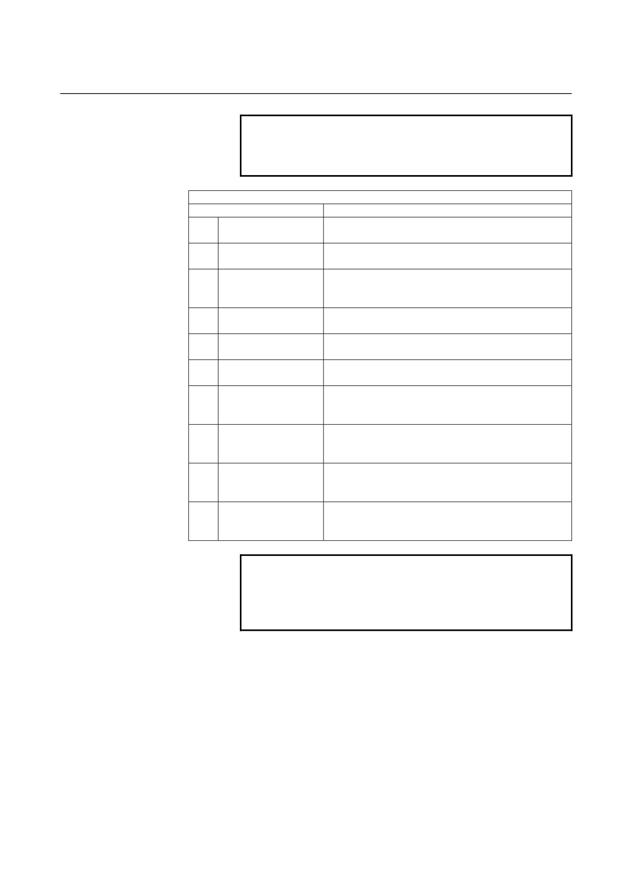
(OUTPUT DATA)
(Note 2)
Data item
Meaning
H
END POINT Z
Z coordinate of the end point of a straight line
(calculation result)
V
END POINT C
C coordinate of the end point of a straight line
(calculation result)
K
LINE DIRECTION
The direction of a straight line is selected from a menu
indicated on a soft key.
(input value)
C*
END POINT Z
Z coordinate of the end point of a straight line
(input value)
D*
END POINT C
C coordinate of the end point of a straight line
(input value)
A*
ANGLE
Straight-line angle
(input value)
L
LAST CONNECTION
[1] : In contact with the immediately preceding figure
[0] : Not in contact with the immediately preceding figure
(input value)
M
NEXT CONNECTION
[1] : In contact with the immediately following figure
[0] : Not in contact with the immediately following figure
(input value)
T
ELEMENT TYPE
[1] : Cut as parts
[2] : Cut as a blank portion
(input value)
S
SELECT FIG. INFO.
In the case of plural intersection or contact, the operator
sets a candidate.
(input value)
NOTE
2
‘OUTPUT DATA’ means the items, which are
displayed on the program window as creating
program. It can be referenced only for program
display purposes.
- 122 -
B-63874EN/05
OPERATION 5.DETAILED DESCRIPTIONS ABOUT ENTERING ARBITRARY FIGURES
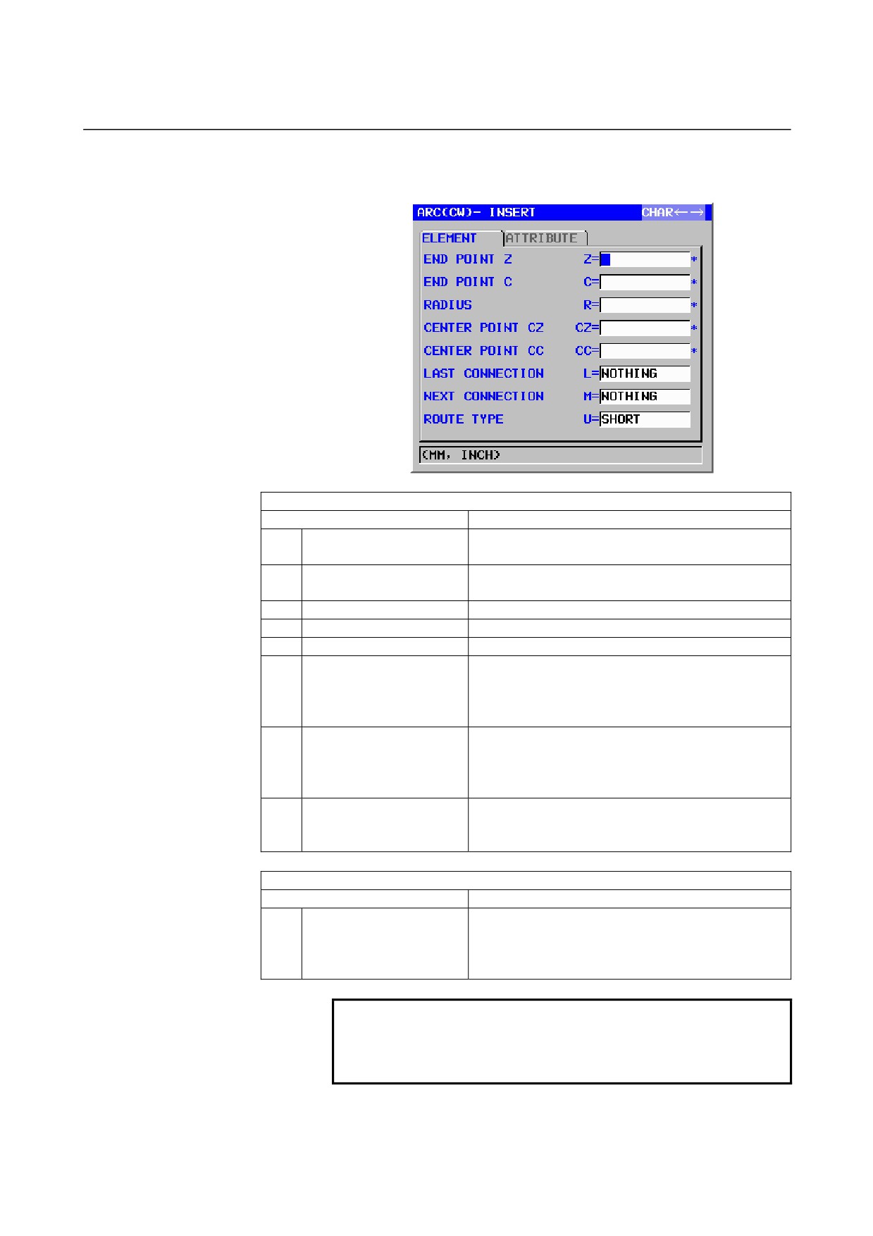
Arc (CW): G1602 (ZC plane)
Arc (CCW): G1603 (ZC plane)
ELEMENT
(INPUT DATA)
(Note 1)
Data item
Meaning
Z*
END POINT Z
Z coordinate of an arc end point
Remarks) Incremental programming is possible.
C*
END POINT C
C coordinate of an arc end point
Remarks) Incremental programming is possible.
R*
RADIUS
Arc radius
CZ*
CENTER POINT CZ
Z coordinate of an arc center
CC*
CENTER POINT CC
C coordinate of an arc center
L
LAST CONNECTION
[TANGNT] : In contact with the immediately
preceding figure
[NO SET]
: Not in contact with the immediately
preceding figure (initial value)
M
NEXT CONNECTION
[TANGNT] : In contact with the immediately
preceding figure
[NO SET]
: Not in contact with the immediately
preceding figure (initial value)
U
ROUTE TYPE
[LONG]
: An arc with a long route is made
[SHORT]
: An arc with a short route is made
(initial value)
ATTRIBUTE
(INPUT DATA)
(Note 1)
Data item
Meaning
T
ELEMENT TYPE
[PART]
: Cut as parts
[BLANK] : Cut as a blank portion
Remarks) The system sets the last data as an initial
value.
NOTE
1
‘INPUT DATA’ means the items, which are
displayed on the input data window in editing or
altering.
- 123 -
5.DETAILED DESCRIPTIONS ABOUT ENTERING ARBITRARY FIGURES OPERATION
B-63874EN/05
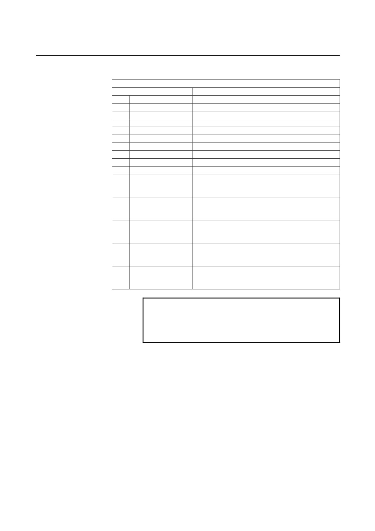
ELEMENT & ATTRIBUTE
(OUTPUT DATA)
(Note 2)
Data item
Meaning
H
END POINT Z
Z coordinate of an arc end point (calculation result)
V
END POINT C
C coordinate of an arc end point (calculation result)
R
RADIUS
Arc radius (calculation result)
I
CENTER POINT Z
Z coordinate of an arc center (calculation result)
J
CENTER POINT C
C coordinate of an arc center (calculation result)
C*
END POINT Z
Z coordinate of an arc end point
(input value)
D*
END POINT C
C coordinate of an arc end point
(input value)
E*
RADIUS
Arc radius
(input value)
P*
CENTER POINT CZ
Z coordinate of an arc center
(input value)
Q*
CENTER POINT CC
C coordinate of an arc center
(input value)
L
LAST CONNECTION
[1] : In contact with the immediately preceding figure
[0] : Not in contact with the immediately preceding figure
(input value)
M
NEXT CONNECTION
[1] : In contact with the immediately preceding figure
[0] : Not in contact with the immediately preceding figure
(input value)
U
ROUTE TYPE
[1] : An arc with a long route is made
[0] : An arc with a short route is made
(input value)
T
ELEMENT TYPE
[1] : Cut as parts
[2] : Cut as a blank portion
(input value)
S
SELECT FIG. INFO.
In the case of plural intersection or contact, the operator
sets a candidate.
(input value)
NOTE
2
‘OUTPUT DATA’ means the items, which are
displayed on the program window as creating
program. It can be referenced only for program
display purposes.
- 124 -
B-63874EN/05
OPERATION 5.DETAILED DESCRIPTIONS ABOUT ENTERING ARBITRARY FIGURES
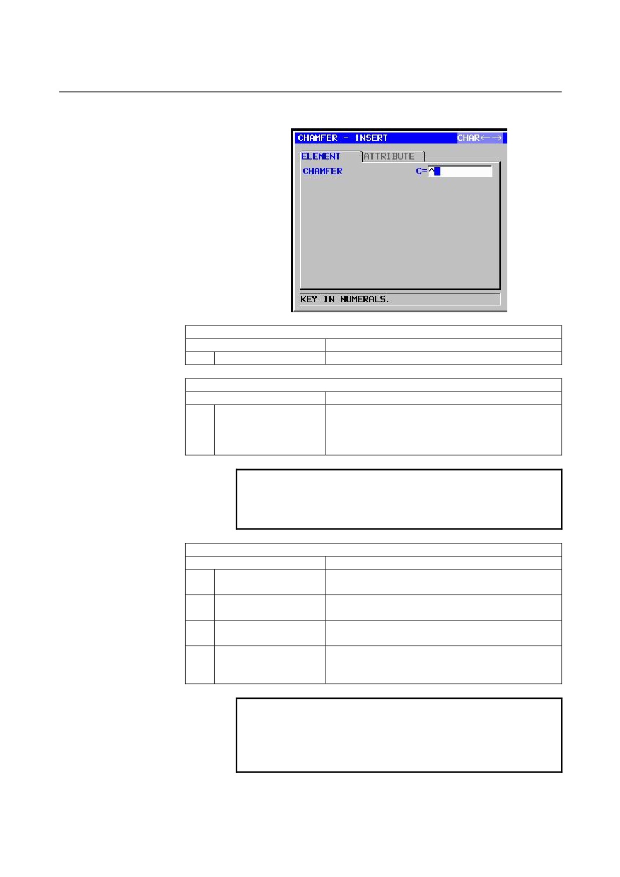
Chamfering: G1604 (ZC plane)
ELEMENT
(INPUT DATA)
(Note 1)
Data item
Meaning
C
CHAMFER
Amount of chamfering (radius value, positive value)
ATTRIBUTE
(INPUT DATA)
(Note 1)
Data item
Meaning
T
ELEMENT TYPE
[PART]
: Cut as parts
[BLANK] : Cut as a blank portion
Remarks) The system sets the last data as an initial
value.
NOTE
1
‘INPUT DATA’ means the items, which are
displayed on the input data window in editing or
altering.
ELEMENT & ATTRIBUTE
(OUTPUT DATA)
(Note 2)
Data item
Meaning
H
END POINT Z
Z coordinate of the end point of a straight line
(calculation result)
V
END POINT C
C coordinate of the end point of a straight line
(calculation result)
C
CHAMFER
Amount of chamfering (radius value, positive value)
(input value)
T
ELEMENT TYPE
[1] : Cut as parts
[2] : Cut as a blank portion
(input value)
NOTE
2
‘OUTPUT DATA’ means the items, which are
displayed on the program window as creating
program. It can be referenced only for program
display purposes.
- 125 -
5.DETAILED DESCRIPTIONS ABOUT ENTERING ARBITRARY FIGURES OPERATION
B-63874EN/05
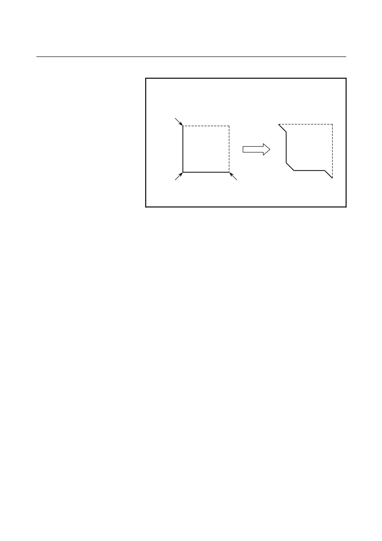
NOTE
3 By setting the parameter No.14851#0=1, Corner
element between a blank element and a part
element can be created in the opposite direction.
C
C
C
C
C
C
Dotted line : blank element
Normal line : part element
- 126 -
B-63874EN/05
OPERATION 5.DETAILED DESCRIPTIONS ABOUT ENTERING ARBITRARY FIGURES
Corner rounding: G1605 (ZC plane)
ELEMENT
(INPUT DATA)
(Note 1)
Data item
Meaning
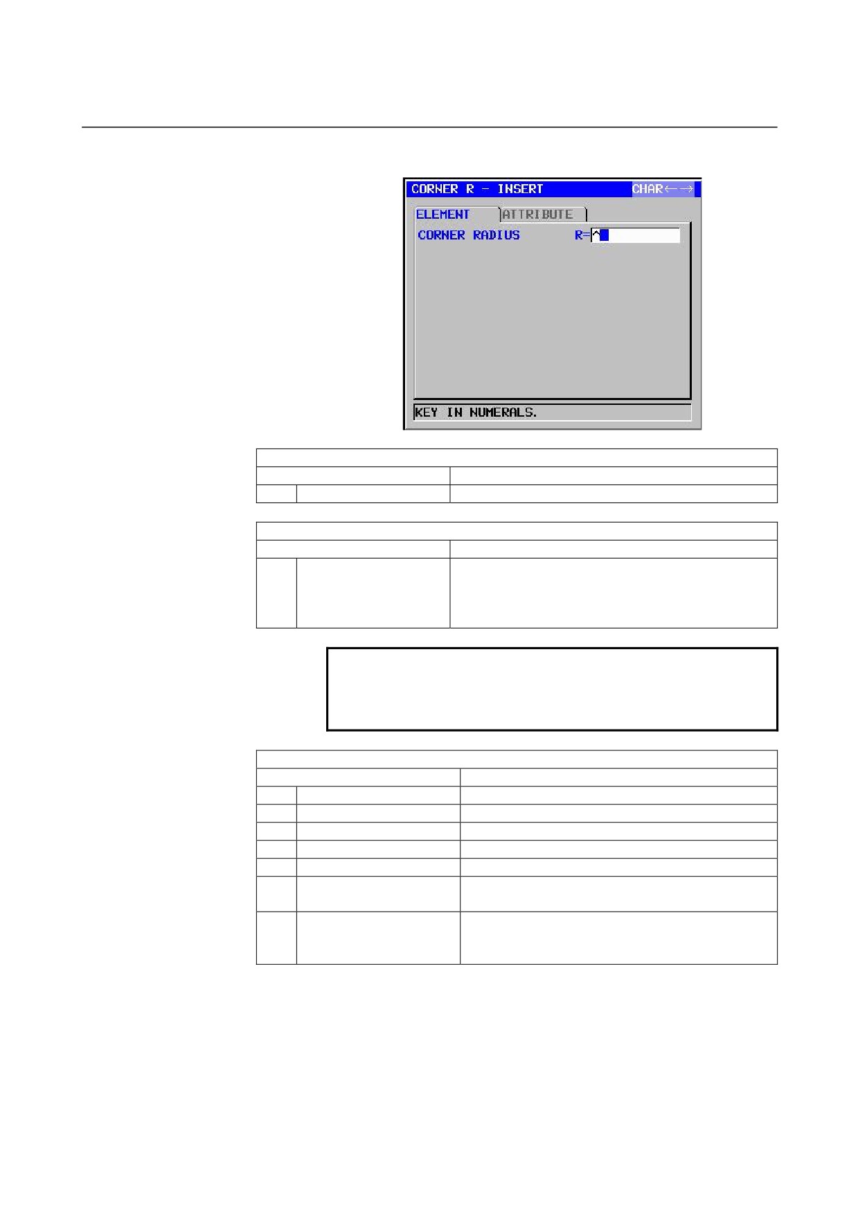
R
CORNER RADIUS
Corner rounding (radius value, positive value)
ATTRIBUTE
(INPUT DATA)
(Note 1)
Data item
Meaning
T
ELEMENT TYPE
[PART]
: Cut as parts
[BLANK] : Cut as a blank portion
Remarks) The system sets the last data as an initial
value.
NOTE
1
‘INPUT DATA’ means the items, which are
displayed on the input data window in editing or
altering.
ELEMENT & ATTRIBUTE
(OUTPUT DATA)
(Note 2)
Data item
Meaning
H
END POINT Z
Z coordinate of an arc end point (calculation result)
V
END POINT C
C coordinate of an arc end point (calculation result)
R
RADIUS
Arc radius
(calculation result)
I
CENTER POINT Z
Z coordinate of an arc center
(calculation result)
J
CENTER POINT C
C coordinate of an arc center
(calculation result)
K
ROTATION DIRECTION
[2] : Clockwise
[3] : Counterclockwise
T
ELEMENT TYPE
[1] : Cut as parts
[2] : Cut as a blank portion
(input value)
- 127 -
5.DETAILED DESCRIPTIONS ABOUT ENTERING ARBITRARY FIGURES OPERATION
B-63874EN/05
NOTE
2
‘OUTPUT DATA’ means the items, which are
displayed on the program window as creating
program. It can be referenced only for program
display purposes.
3 By setting the parameter No.14851#0=1, Corner
element between a blank element and a part
element can be created in the opposite direction.
End of arbitrary figures: G1606 (ZC plane)
This block is output at the end of a series of arbitrary-figure blocks.
NOTE
A series of arbitrary figures must be enclosed
between G1600 (start point) and G1606 (end of
arbitrary figures).
- 128 -
B-63874EN/05
OPERATION 5.DETAILED DESCRIPTIONS ABOUT ENTERING ARBITRARY FIGURES
5.5
ARBITRARY FIGURES FOR TURNING (ZX PLANE)
Arbitrary figures in the ZX plane can be used in turning.
1. Outer surface rough/semifinish/finish turning
2. Inner surface rough/semifinish/finish turning
3. End surface rough/semifinish/finish turning
NOTE
1 See Section 2.1, "Turning," in Part III for detailed
descriptions about data to be entered for each type
of cycle machining.
2 When entering an arbitrary figure for turning, make
its end point coincide with its start point. To put
another way, combine parts figures with blank
figures in such a way that a closed curve is
created.
Turning is carried out in this closed curve.
3 It is possible to specify "PART" and "BLANK" as
"ELEMENT TYPE" for an individual arbitrary figure.
This "BLANK" can be used to enter an arbitrary
figure resembling a blank figure to be actually
machined, so any portion other than the blank
portion will not be cut. This way, optimum rough
turning can be realized.
Start point: G1450 (ZX plane)
ELEMENT
(INPUT DATA)
(Note 1)
Data item
Meaning
DX
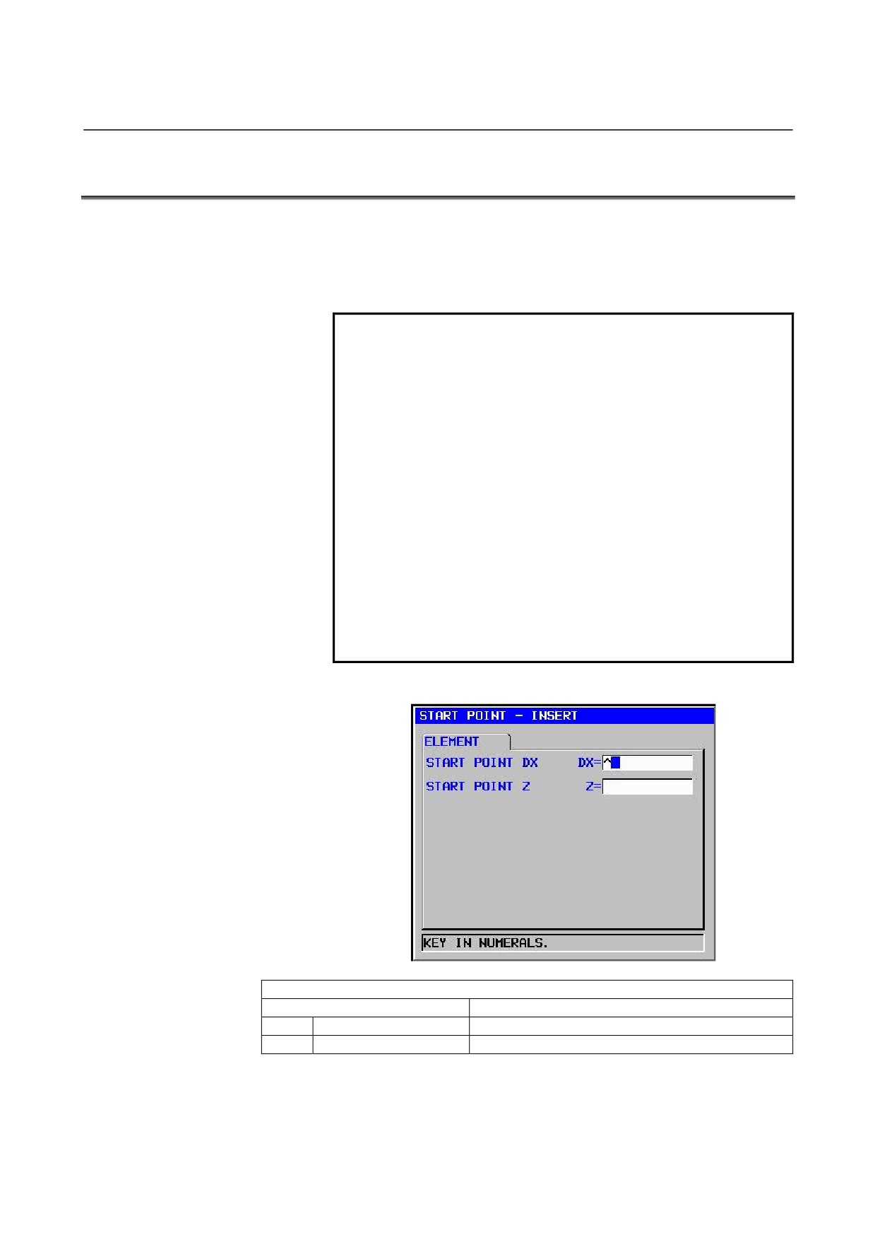
START POINT DX
X coordinate of the start point of an arbitrary figure
Z
START POINT Z
Z coordinate of the start point of an arbitrary figure
- 129 -
5.DETAILED DESCRIPTIONS ABOUT ENTERING ARBITRARY FIGURES OPERATION
B-63874EN/05
NOTE
1
‘INPUT DATA’ means the items, which are
displayed on the input data window in editing or
altering.
ELEMENT
(OUTPUT DATA)
(Note 2)
Data item
Meaning
H
START POINT DX
X coordinate of the start point
(input value)
V
START POINT Z
Z coordinate of the start point
(input value)
NOTE
2
‘OUTPUT DATA’ means the items, which are
displayed on the program window as creating
program. It can be referenced only for program
display purposes.
- 130 -
B-63874EN/05
OPERATION 5.DETAILED DESCRIPTIONS ABOUT ENTERING ARBITRARY FIGURES
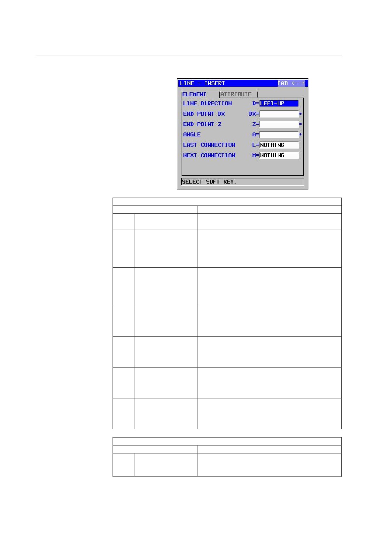
Straight line: G1451 (ZX plane)
ELEMENT
(INPUT DATA)
(Note 1)
Data item
Meaning
D
LINE DIRECTION
The direction of a straight line is selected from a menu
indicated on a soft key.
DX*
END POINT DX
X coordinate of the end point of a straight line
Remarks1) This data may not be displayed depending
on the value entered as the direction of the
straight line.
Remarks2) Incremental programming is possible.
Z*
END POINT Z
Z coordinate of the end point of a straight line
Remarks1) This data may not be displayed depending
on the value entered as the direction of the
straight line.
Remarks2) Incremental programming is possible.
A*
ANGLE
Straight-line angle
Remarks) This data may not be displayed
depending on the value entered as the
direction of the straight line.
L
LAST CONNECTION
[TANGNT] : In contact with the immediately preceding
figure
[NO SET] : Not in contact with the immediately
preceding figure (initial value)
M
NEXT CONNECTION
[TANGNT] : In contact with the immediately following
figure
[NO SET] : Not in contact with the immediately
following figure (initial value)
T
ELEMENT TYPE
[PART]
: Cut as parts
[BLANK] : Cut as a blank portion
Remarks) The system sets the last data as an initial
value.
ATTRIBUTE
(INPUT DATA)
(Note 1)
Data item
Meaning
F
FINISH FEEDRATE
Cutting feedrate for finishing (positive value)
Remarks) It is possible to set the feedrate to each
block on Finishing.
- 131 -