FANUC Series 0i-MODEL D, Series 0i Mate-MODEL D. OPERATOR'S MANUAL - page 29
A.PARAMETERS
APPENDIX
B-64304EN/02
#3 OSR Pressing the [O SEARCH] soft key without entering a program number with keys in a
program number search:
0: Searches for the next program number (order of registration).
1: Disables the search.
#4
NE9 Editing of subprograms with program numbers 9000 to 9999
0: Not inhibited
1: Inhibited
When this parameter is set to 1, the following editing operations are disabled:
(1) Program deletion (Even when deletion of all programs is specified, programs with
program numbers 9000 to 9999 are not deleted.)
(2) Program output (Even when outputting all programs is specified, programs with
program numbers 9000 to 9999 are not output.)
(3) Program number search
(4) Program editing of registered programs
(5) Program registration
(6) Program collation
(7) Displaying programs
NOTE
This parameter setting does not affect the following programs:
(1) Programs on the Data Server
(2) Programs for running and editing memory card programs on a
memory card
#7
#6
#5
#4
#3
#2
#1
#0
3203
MCL
MER
MZE
[Input type] Parameter input
[Data type] Bit path
#5 MZE After MDI operation is started, program editing during operation is:
0: Enabled
1: Disabled
#6 MER When the last block of a program has been executed at single block operation in the MDI
mode, the executed block is:
0: Not deleted
1: Deleted
NOTE
When MER is set to 0, the program is deleted if the end-of-record
mark (%) is read and executed. (The mark % is automatically
inserted at the end of a program.)
#7 MCL Whether a program prepared in the MDI mode is cleared by reset
0: Not deleted
1: Deleted
#7
#6
#5
#4
#3
#2
#1
#0
3204
MKP
[Input type] Parameter input
[Data type] Bit path
- 816 -
B-64304EN/02
APPENDIX
A.PARAMETERS
#6 MKP When M02, M30, or EOR(%) is executed during MDI operation, the created MDI
program is:
0: Erased automatically.
1: Not erased automatically.
NOTE
If the bit 6 (MER) of parameter No. 3203 is 1, executing the last
block provides a choice of whether to automatically erase a created
program.
#7
#6
#5
#4
#3
#2
#1
#0
3205
PNS
TOK
[Input type] Parameter input
[Data type] Bit
#2 TOK A WORD COPY or WORD MOVE on the program screen:
0: Is performed as usual.
1: Can also be performed on a record-by-record basis from a program to the key-in
buffer.
#3 PNS On the program screen, a search with the cursor keys is:
0: Performed.
1: Not performed.
#7
#6
#5
#4
#3
#2
#1
#0
3207
VRN
[Input type] Parameter input
[Data type] Bit
#5 VRN On the custom macro variable screen, the variable names of common variables #500 to
#549 are:
0: Not displayed.
1: Displayed.
3210
Program protection
[Input type] Parameter input
[Data type] 2-word
[Valid data range] 0 to 99999999
This parameter sets a password for protecting program Nos. 9000 to 9999. When a value
other than zero is set in this parameter and this value differs from the keyword set in
parameter No.3211, bit 4 (NE9) of parameter No.3202 for protecting program Nos. 9000
to 9999 is automatically set to 1.
This disables the editing of program Nos. 9000 to 9999. Until the value set as the
password is set as a keyword, NE9 cannot be set to 0 and the password cannot be
modified.
- 817 -
A.PARAMETERS
APPENDIX
B-64304EN/02
NOTE
1 The state where password ≠ 0 and password ≠ keyword is referred
to as the locked state. When an attempt is made to modify the
password by MDI input operation in this state, the warning
message "WRITE PROTECTED" is displayed to indicate that the
password cannot be modified. When an attempt is made to modify
the password with G10 (programmable parameter input), alarm
(PS0231) is issued.
2 When the value of the password is not 0, the parameter screen
does not display the password. Care must be taken in setting a
password.
3211
Program protection key
[Input type] Parameter input
[Data type] 2-word
[Valid data range] 0 to 99999999
When the value set as the password (set in parameter No.3210) is set in this parameter,
the locked state is released and the user can now modify the password and the value set in
bit 4 (NE9) of parameter No.3202.
NOTE
The value set in this parameter is not displayed. When the power is
turned off, this parameter is set to 0.
#7
#6
#5
#4
#3
#2
#1
#0
3280
NLC
[Input type] Parameter input
[Data type] Bit
#0 NLC Dynamic display language switching is:
0: Enabled.
1: Disabled.
When dynamic display language switching is disabled, the language setting screen is not
displayed. In this case, change the setting of parameter No. 3281 on the parameter screen
then turn on the power again to switch the display language.
3281
Display language
[Input type] Parameter input
[Data type] Byte
[Valid data range] 0 to 18
Select a display language from the following:
0 : English
1 : Japanese
2 : German
3 : French
4 : Chinese(traditional characters)
5 : Italian
6 : Korean
7 : Spanish
8 : Dutch
- 818 -
B-64304EN/02
APPENDIX
A.PARAMETERS
9 : Danish
10 : Portuguese
11 : Polish
12 : Hungarian
13 : Swedish
14 : Czech
15 : Chinese(simplified characters)
16 : Russian
17 : Turkish
18 : Bulgarian
If a number not indicated above is set, English is selected.
#7
#6
#5
#4
#3
#2
#1
#0
GSC
GSB
ABS
MAB
DPI
3401
ABS
MAB
DPI
[Input type] Parameter input
[Data type] Bit path
#0 DPI When a decimal point is omitted in an address that can include a decimal point
0: The least input increment is assumed. (Normal decimal point input)
1: The unit of mm, inches, degree, or second is assumed. (Pocket calculator type
decimal point input)
#4 MAB Switching between the absolute and incremental commands in MDI operation
0: Performed by G90 or G91
1: Depending on the setting of bit 5 (ABS) of parameter No.3401
NOTE
When G code system A of the T series is used, this parameter is
invalid.
#5 ABS Program command in MDI operation
0: Assumed as an incremental command
1: Assumed as an absolute command
NOTE
ABS is valid when bit 4 (MAB) of parameter No.3401 is set to 1.
When G code system A of the T series is used, this parameter is
invalid.
#6 GSB The G code system is set.
#7 GSC
GSC
GSB
G code
0
0
G code system A
0
1
G code system B
1
0
G code system C
#7
#6
#5
#4
#3
#2
#1
#0
G23
CLR
FPM
G91
G01
3402
G23
CLR
G91
G19
G18
G01
[Input type] Parameter input
- 819 -
A.PARAMETERS
APPENDIX
B-64304EN/02
[Data type] Bit path
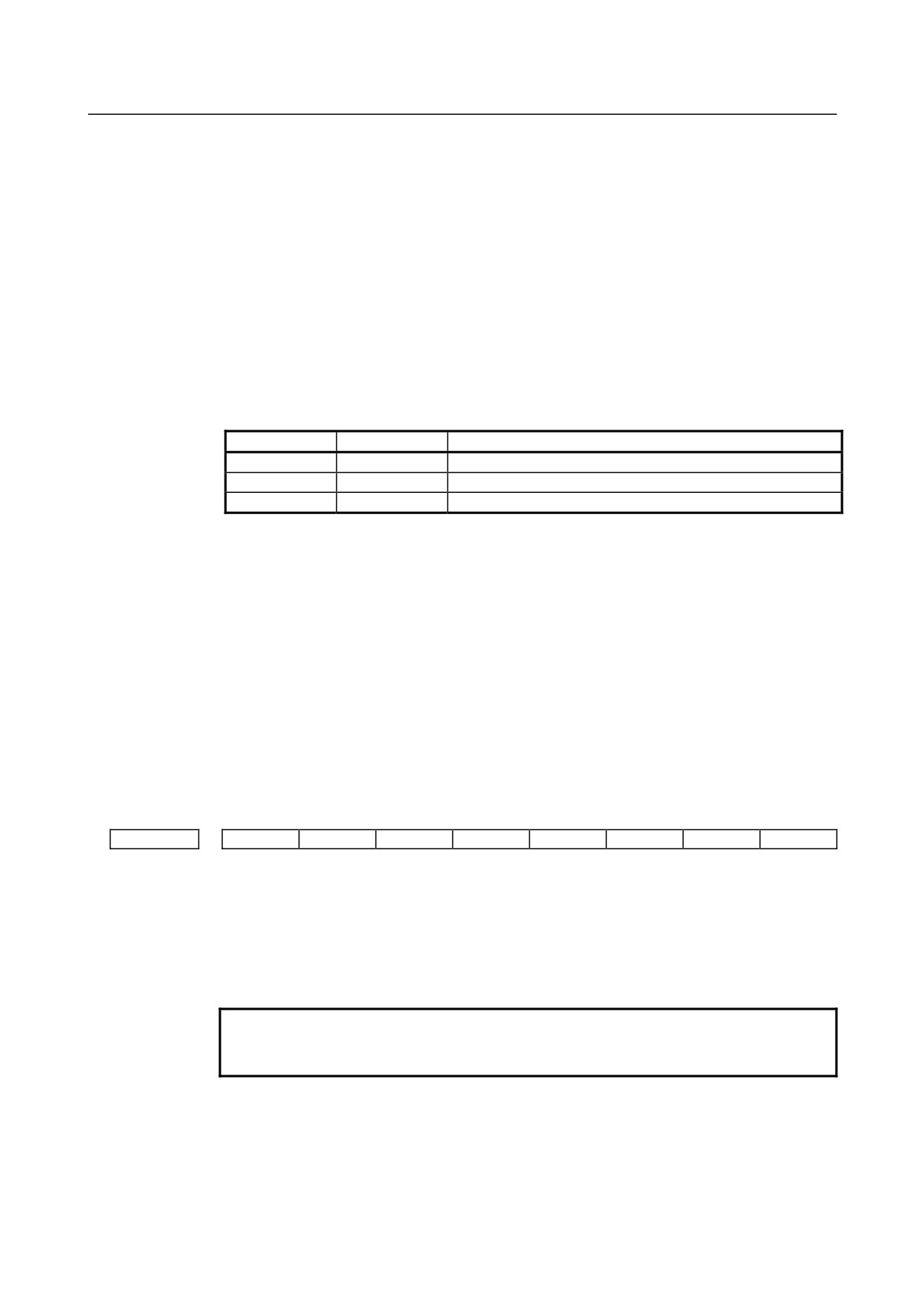
#0 G01 G01 Mode entered when the power is turned on or when the control is cleared
0: G00 mode (positioning)
1: G01 mode (linear interpolation)
#1 G18 Plane selected when power is turned on or when the control is cleared
0: G17 mode (plane XY)
1: G18 mode (plane ZX)
#2 G19 Plane selected when power is turned on or when the control is cleared
0: The setting of bit 1 (G18) of parameter No.3402 is followed.
1: G19 mode (plane YZ)
When this bit is set to 1, set bit 1 (G18) of parameter No.3402 to 0.
G19
G18
G17, G18, or G19 mode
0
0
G17 mode (X-Y plane)
0
1
G18 mode (Z-X plane)
1
0
G19 mode (Y-Z plane)
#4 FPM At power-on time or in the cleared state:
0: G99 or G95 mode (feed per revolution) is set.
1: G98 or G94 mode (feed per minute) is set.
#6 CLR Reset button on the MDI panel, external reset signal, reset and rewind signal, and
emergency stop signal
0: Cause reset state.
1: Cause clear state.
For the reset and clear states, refer to Appendix in the OPERATOR’S MANUAL.
#7 G23 When the power is turned on
0: G22 mode (stored stroke check on)
1: G23 mode (stored stroke check off)
#7
#6
#5
#4
#3
#2
#1
#0
3404
M3B
M02
M30
SBP
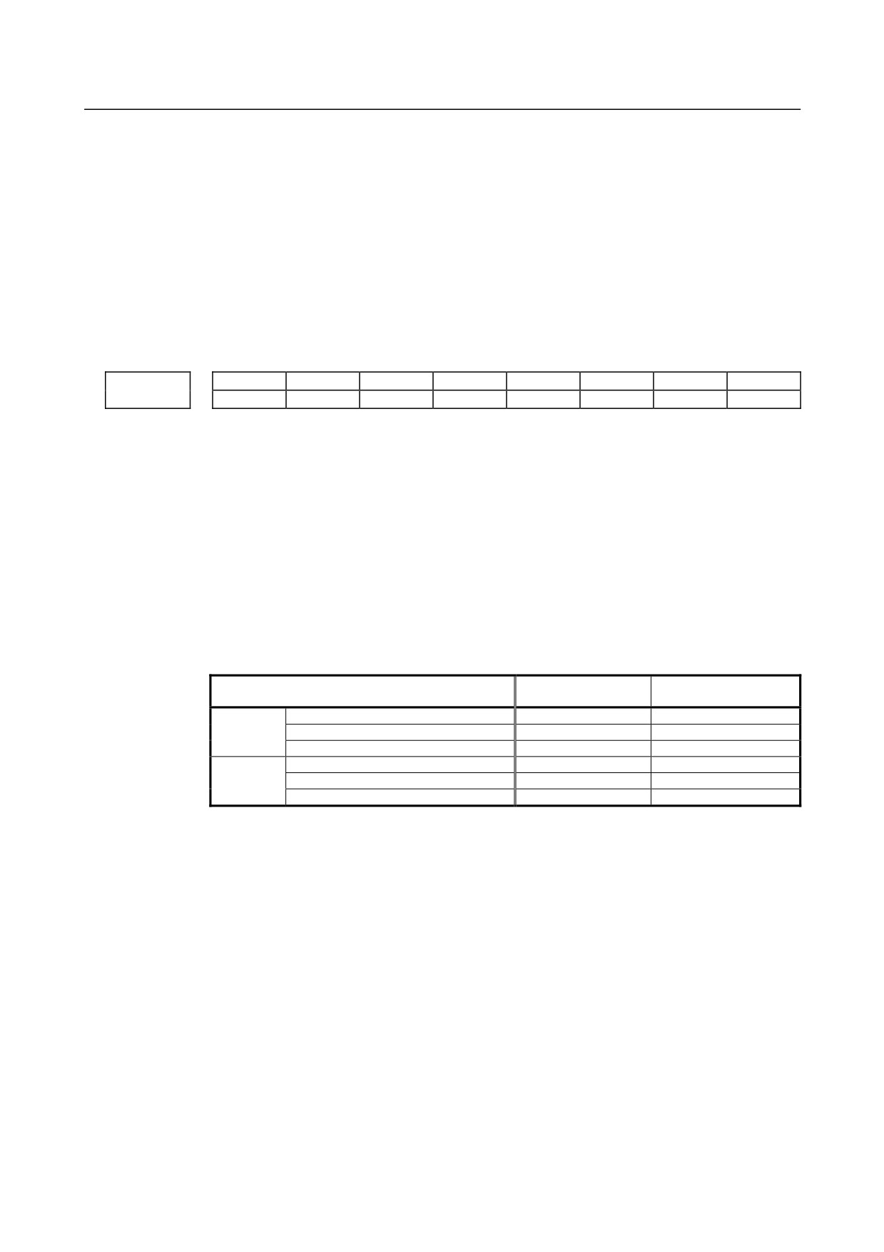
[Input type] Parameter input
[Data type] Bit path
#2 SBP In an external device subprogram call (M198), the address P format is based on:
0: File number specification
1: Program number specification
NOTE
In memory card operation, the program number specification
format is used, regardless of the setting of this parameter.
#4 M30 When M30 is specified in a memory operation:
0: M30 is sent to the machine, and the head of the program is automatically searched
for. So, when the ready signal FIN is returned and a reset or reset and rewind
operation is not performed, the program is executed, starting from the beginning.
1: M30 is sent to the machine, but the head of the program is not searched for. (The
head of the program is searched for by the reset and rewind signal.)
- 820 -
B-64304EN/02
APPENDIX
A.PARAMETERS
#5 M02 When M02 is specified in memory operation
0: M02 is sent to the machine, and the head of the program is automatically searched
for. So, when the end signal FIN is returned and a reset or reset and rewind
operation is not performed, the program is executed, starting from the beginning.
1: M02 is sent to the machine, but the head of the program is not searched for. (The
head of the program is searched for by the reset and rewind signal.)
#7 M3B The number of M codes that can be specified in one block
0: One
1: Up to three
#7
#6
#5
#4
#3
#2
#1
#0
CCR
DWL
AUX
3405
DWL
AUX
[Input type] Parameter input
[Data type] Bit path
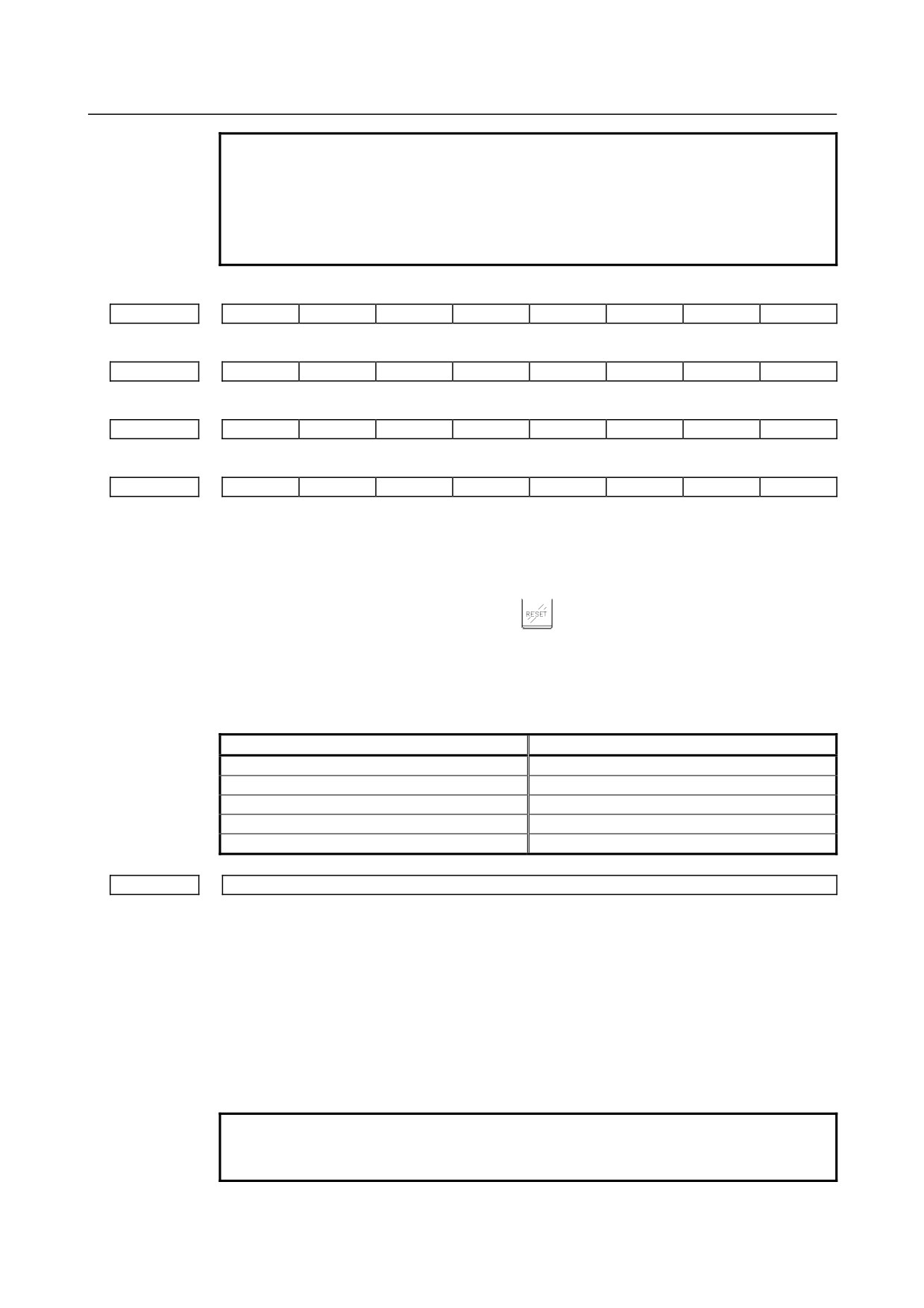
#0 AUX When the second auxiliary function is specified in the calculator-type decimal point input
format or with a decimal point, the multiplication factor for a value output (onto the code
signal) relative to a specified value is such that:
0: The same multiplication factor is used for both of metric input and inch input.
1: A multiplication factor used for inch input is 10 times greater than that used for
metric input.
When the second auxiliary function is specified in the calculator-type decimal point input
format or with a decimal point, the value output onto the code signal is a specified value
multiplied by a value indicated below.
Increment system
Parameter AUX=0
Parameter AUX=1
Metric
IS-A for reference axis
100 times
100 times
input
IS-B for reference axis
1000 times
1000 times
system
IS-C for reference axis
10000 times
10000 times
IS-A for reference axis
100 times
1000 times
Inch input
IS-B for reference axis
1000 times
10000 times
system
IS-C for reference axis
10000 times
100000 times
#1 DWL The dwell time (G04) is:
0: Always dwell per second.
1: Dwell per second in the feed per minute mode, or dwell per rotation in the feed per
rotation mode.
#4 CCR Addresses used for chamfering
0: Address is “I”, “J”, or “K”.
In direct drawing dimension programming, addresses ",C", ",R", and ",A" (with
comma) are used in stead of "C", "R", and "A".
1: Address is “C”.
Addresses used for direct drawing dimension programming are "C", "R", and "A"
without comma.
- 821 -
A.PARAMETERS
APPENDIX
B-64304EN/02
NOTE
If this bit (CCR) is set to 0, the function for changing the
compensation direction by specifying I, J, or K in a G01 block in the
tool nose radius compensation mode cannot be used.
If this bit (CCR) is set to 1 when address C is used as an axis
name, the chamfer function cannot be used.
#7
#6
#5
#4
#3
#2
#1
#0
3406
C07
C06
C05
C04
C03
C02
C01
#7
#6
#5
#4
#3
#2
#1
#0
3407
C15
C14
C13
C12
C11
C10
C09
C08
#7
#6
#5
#4
#3
#2
#1
#0
3408
C23
C22
C21
C20
C19
C18
C17
C16
#7
#6
#5
#4
#3
#2
#1
#0
3409
C30
C29
C28
C27
C26
C25
C24
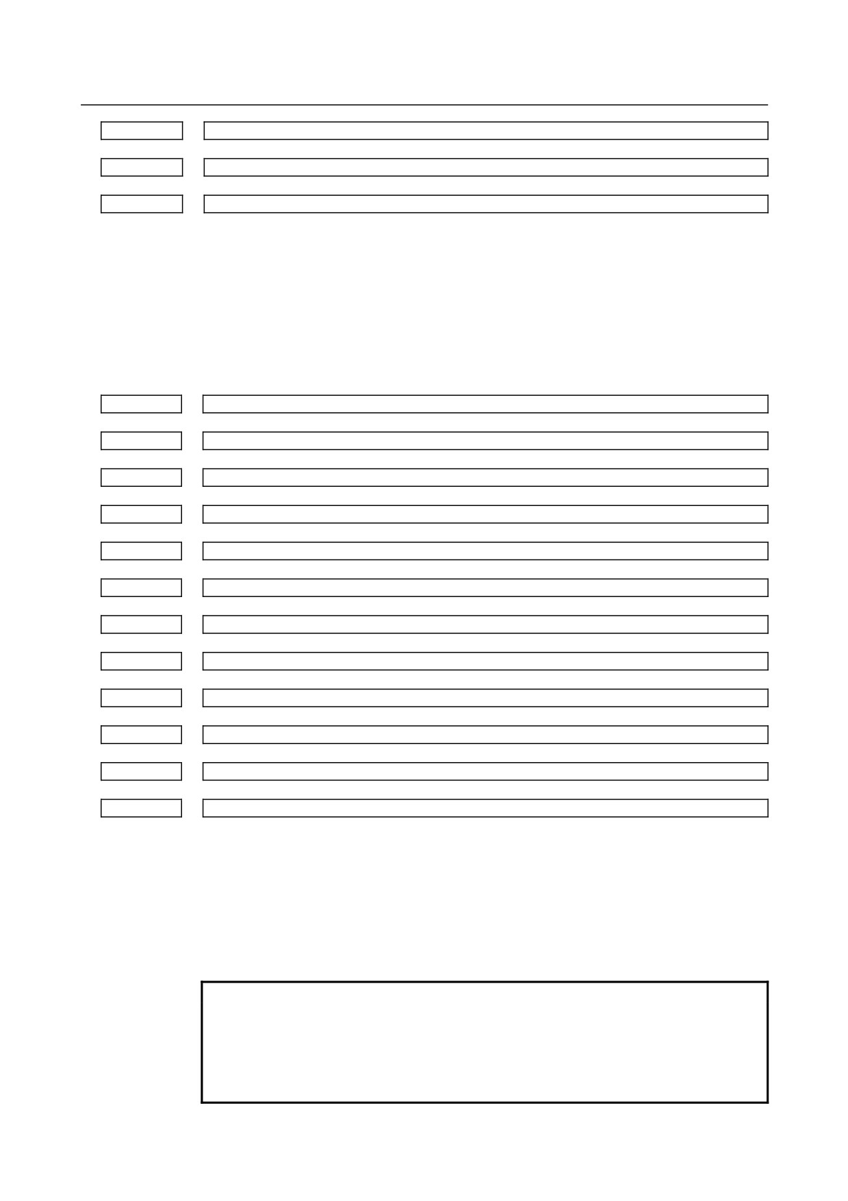
[Input type] Parameter input
[Data type] Bit
C01 to C30 If bit 6 (CLR) of parameter No.3402 is set to 1, set a group of G codes to be placed in the
cleared state when the CNC is reset by the
key of the MDI panel, the external reset
signal, the reset & rewind signal, or the emergency stop signal.
The table below indicates the correspondence between bits and G code groups
The setting of a bit has the following meaning:
0: Places the G code group in the cleared state.
1: Does not place G code group in the cleared state.
Parameter
G code group
C01
01
C02
02
C03
03
:
:
C30
30
3410
Tolerance of arc radius
[Input type] Setting input
[Data type] Real path
[Unit of data] mm, inch (input unit)
[Min. unit of data] Depend on the increment system of the reference axis
[Valid data range] 0 or positive 9 digit of minimum unit of data (refer to the standard parameter setting table
(B))
(When the increment system is IS-B, 0.0 to +999999.999)
When a circular interpolation command is executed, the tolerance for the radius between
the start point and the end point is set.
NOTE
When the setting is 0, the difference between the arc radius values
is not checked.
- 822 -
B-64304EN/02
APPENDIX
A.PARAMETERS
3411
M code preventing buffering 1
3412
M code preventing buffering 2
:
3420
M code preventing buffering 10
[Input type] Parameter input
[Data type] 2-word path
[Valid data range] 3 to 99999999
Set M codes that prevent buffering the following blocks. If processing directed by an M
code must be performed by the machine without buffering the following block, specify
the M code.
M00, M01, M02, and M30 always prevent buffering even when they are not specified in
these parameters.
3421
Range specification 1 of M codes that do not perform buffering (lower limit)
3422
Range specification 1 of M codes that do not perform buffering (upper limit)
3423
Range specification 2 of M codes that do not perform buffering (lower limit)
3424
Range specification 2 of M codes that do not perform buffering (upper limit)
3425
Range specification 3 of M codes that do not perform buffering (lower limit)
3426
Range specification 3 of M codes that do not perform buffering (upper limit)
3427
Range specification 4 of M codes that do not perform buffering (lower limit)
3428
Range specification 4 of M codes that do not perform buffering (upper limit)
3429
Range specification 5 of M codes that do not perform buffering (lower limit)
3430
Range specification 5 of M codes that do not perform buffering (upper limit)
3431
Range specification 6 of M codes that do not perform buffering (lower limit)
3432
Range specification 6 of M codes that do not perform buffering (upper limit)
[Input type] Parameter input
[Data type] 2-word path
[Valid data range] 3 to 99999999
When a specified M code is within the range specified with parameter Nos.3421 and 3422,
3423 and 3424, 3425 and 3426, 3427 and 3428, 3429 and 3430, or 3431 and 3432,
buffering for the next block is not performed until the execution of the block is
completed.
NOTE
1 M00, M01, M02, and M30 are M codes that do not perform
buffering, regardless of parameter setting.
M98, M99, M codes for calling subprograms, and M codes for
calling custom macros are M codes that performs buffering,
regardless of parameter setting.
- 823 -
A.PARAMETERS
APPENDIX
B-64304EN/02
NOTE
2 If the minimum value is greater than the maximum value, the
setting is invalid.
3 If there is only one data item, the minimum value must be equal to
the maximum value.
#7
#6
#5
#4
#3
#2
#1
#0
3450
BDX
AUP
[Input type] Parameter input
[Data type] Bit path
#0 AUP The second auxiliary function specified in the calculator-type decimal point input format,
with a decimal point, or with a negative value is:
0: Disabled.
1: Enabled.
If the second auxiliary function is specified after setting this bit to 0, the following
operation results:
1.
When a value is specified without a decimal point
A specified value is output onto the code signal without modification, regardless of
the setting of the calculator-type decimal point input format (with bit 0 (DPI) of
parameter No. 3401).
2.
When a value is specified with a decimal point
The alarm (PS0007) is issued.
3.
When a negative value is specified
The alarm (PS0006) is issued.
#7
BDX This parameter prevents the unit of the argument from depending on the setting of bit 2
(BCD) of parameter No. 8132 when a subprogram call by an ASCII code is performed
with the address (specified by parameter No. 3460) of the second auxiliary function.
0: When bit 0 (AUP) of parameter No. 3450 is 1, the unit of the argument depends on
the setting of bit 2 (BCD) of parameter No. 3450.
1: The same unit of the argument is used. The unit when bit 2 (BCD) of parameter
No. 8132 is 1 is specified.
[Example]
A setting is made so that address B is used to call O9004, and the program O1 below is
executed with parameter No.3460 = 66.
O1
O9004
B2
#500 = #146
M30 M99
When the increment system is IS-B, and metric input is used, #500 assumes a value
indicated in the table below.
BDX=0
Parameter DPI
Parameter AUP
Parameter
Parameter
BDX=1
(No.3401#0)
(No.3450#0)
BCD(No.8132#2)=0
BCD(No.8132#2)=1
0
2.000
2.000
2.000
0
1
2.000
0.002
0.002
0
2.000
2.000
2.000
1
1
2.000
2.000
2.000
- 824 -
B-64304EN/02
APPENDIX
A.PARAMETERS
#7
#6
#5
#4
#3
#2
#1
#0
3451
GQS
[Input type] Parameter input
[Data type] Bit path
#0 GQS When threading is specified, the threading start angle shift function (Q) is:
0: Disabled.
1: Enabled.
#7
#6
#5
#4
#3
#2
#1
#0
3452
EAP
[Input type] Parameter input
[Data type] Bit path
#7 EAP When bit 0 (ADX) of parameter No.3455 is set to 1, calculator-type decimal point input
at a macro calling argument address is:
0: Enabled.
1: Disabled.
NOTE
This parameter is valid when bit 0 (DPI) of parameter No.3401 is
set to 0.
#7
#6
#5
#4
#3
#2
#1
#0
3454
G1B
[Input type] Parameter input
[Data type] Bit path
#4 G1B In programmable parameter input, specifying a change to a specific bit parameter is:
0: Disabled.
1: Enabled. (A bit number is specified with Q_.)
#7
#6
#5
#4
#3
#2
#1
#0
3455
AXDx
[Input type] Parameter input
[Data type] Bit axis
#0 AXDx If a decimal point is omitted for an axis address with which a decimal point can be used,
the value is determined:
0: In accordance with the least input increment. (Normal decimal point input)
1: In millimeters, inches, or seconds. (calculator-type decimal point input)
NOTE
This parameter specifies the calculator-type decimal point input
function for each axis.
For the same axis name, be sure to make the same setting.
- 825 -
A.PARAMETERS
APPENDIX
B-64304EN/02
3460
Second auxiliary function specification address
[Input type] Parameter input
[Data type] Byte path
[Valid data range] 65to67, 85to87
Specify which of A, B, C, U, V, and W is to be used as the address for specifying the
second auxiliary function. If an address used as an axis name is specified, the second
auxiliary function is disabled.
Name
A
B
C
U
V
W
Setting value
65
66
67
85
86
87
Address B is assumed when a value other than the above is set.
However, the name U, V, or W can be used with the T series only when G code system B
or C is used. When a value from 85 to 87 is specified with G code system A, the
specification address for the second auxiliary function is B.
#7
#6
#5
#4
#3
#2
#1
#0
3605
BDPx
[Input type] Parameter input
[Data type] Bit axis
NOTE
When this parameter is set, the power must be turned off before
operation is continued.
#0 BDPx Both-direction pitch error compensation is:
0: Not used.
1: Used.
NOTE
The both-direction pitch error compensation option is required.
3620
Number of the pitch error compensation position for the reference position for each axis
NOTE
When this parameter is set, the power must be turned off before
operation is continued.
[Input type] Parameter input
[Data type] Word axis
[Valid data range] 0 to 1023
Set the number of the pitch error compensation position for the reference position for
each axis.
3621
Number of the pitch error compensation position at extremely negative position for each axis
NOTE
When this parameter is set, the power must be turned off before
operation is continued.
[Input type] Parameter input
[Data type] Word axis
[Valid data range] 0 to 1023
- 826 -
B-64304EN/02
APPENDIX
A.PARAMETERS
Set the number of the pitch error compensation position at the extremely negative
position for each axis.
3622
Number of the pitch error compensation position at extremely positive position for each axis
NOTE
When this parameter is set, the power must be turned off before
operation is continued.
[Input type] Parameter input
[Data type] Word axis
[Valid data range] 0 to 1023
Set the number of the pitch error compensation position at the extremely positive position
for each axis.
This value must be larger than set value of parameter (No.3620).
3623
Magnification for pitch error compensation for each axis
NOTE
When this parameter is set, the power must be turned off before
operation is continued.
[Input type] Parameter input
[Data type] Byte axis
[Valid data range] 0 to 100
Set the magnification for pitch error compensation for each axis.
If the magnification is set to 1, the same unit as the detection unit is used for
the
compensation data.
If 0 is set, compensation is not performed.
3624
Interval between pitch error compensation positions for each axis
NOTE
When this parameter is set, the power must be turned off before
operation is continued.
[Input type] Parameter input
[Data type] Real axis
[Unit of data] mm, inch, degree (machine unit)
[Min. unit of data] Depend on the increment system of the applied axis
[Valid data range] See the description below.
The pitch error compensation positions are arranged with equal spacing. The space
between two adjacent positions is set for each axis. The minimum interval between pitch
error compensation positions is limited and obtained from the following equation:
Minimum interval between pitch error compensation positions = maximum feedrate/7500
Unit : Minimum interval between pitch error compensation positions: mm, inch, deg
Maximum feedrate: mm/min, inch/min, deg/min
Example:
When the maximum feedrate is 15000 mm/min, the minimum interval between pitch
error compensation positions is 2 mm.
- 827 -
A.PARAMETERS
APPENDIX
B-64304EN/02
3625
Travel distance per revolution in pitch error compensation of rotation axis type
NOTE
When this parameter is set, the power must be turned off before
operation is continued.
[Input type] Parameter input
[Data type] Real axis
[Unit of data] mm, inch, degree (machine unit)
[Min. unit of data] Depend on the increment system of the applied axis
[Valid data range] See the description below.
If the pitch error compensation of rotation axis type is performed (bit 1 (ROSx) of
parameter No.1006 is set to 0 and bit 0 (ROTx) of parameter No.1006 is set to 1), set the
travel distance per revolution. The travel distance per revolution does not have to be 360
degrees, and a cycle of pitch error compensation of rotation axis type can be set.
However, the travel distance per revolution, compensation interval, and number of
compensation points must satisfy the following condition:
(Travel distance per revolution)
= (Compensation interval) × (Number of compensation points)
The compensation at each compensation point must be set so that the total compensation
per revolution equals 0.
NOTE
If 0 is set, the travel distance per revolution becomes 360 degrees.
Number of the both-direction pitch error compensation position at extremely negative position (for
3626
movement in the negative direction)
NOTE
When this parameter is set, the power must be turned off before
operation is continued.
[Input type] Parameter input
[Data type] Word axis
[Valid data range] 0 to 1023, 3000 to 4023
When using both-direction pitch error compensation, set the number of compensation
point at the farthest end in the negative direction for a movement in the negative
direction.
NOTE
1 For a movement in the positive direction, set the compensation point
number at the farthest end in the negative direction in parameter
No.3621.
2 A set of compensation data items for a single axis should not be set
to lie astride 1023 to 3000.
- 828 -
B-64304EN/02
APPENDIX
A.PARAMETERS
Pitch error compensation at reference position when a movement to the reference position is made
3627
from the direction opposite to the direction of reference position return
NOTE
When this parameter is set, the power must be turned off before
operation is continued.
[Input type] Parameter input
[Data type] Word axis
[Unit of data] Detection unit
[Valid data range] -32768 to 32767
Set the absolute value of pitch error compensation at reference position when a movement
to the reference position is made from the negative direction if the direction of reference
position return (bit
5 (ZMI) of parameter No.1006) is positive or from the positive
direction if the direction of reference position return is negative.
#7
#6
#5
#4
#3
#2
#1
#0
3700
NRF
[Input type] Parameter input
[Data type] Bit path
#1 NRF With the first move command (G00) after switching the serial spindle to Cs contour
control axis:
0: A reference position return operation is once performed then positioning
is
performed.
1: A normal positioning operation is performed.
NOTE
1 When using the Cs axis establishment function, this parameter is
recommended to be set to 1.
2 The setting of this parameter is valid for G00. The first rapid
traverse of a canned cycle is normal positioning regardless of the
setting of this parameter.
#7
#6
#5
#4
#3
#2
#1
#0
EMS
3702
[Input type] Parameter input
[Data type] Bit path
#1 EMS The multi-spindle control function is:
0: Used.
1: Not used.
NOTE
Make the setting on the side of the path in which multi-spindle
control is unnecessary in 2-path control.
- 829 -
A.PARAMETERS
APPENDIX
B-64304EN/02
#7
#6
#5
#4
#3
#2
#1
#0
3716
A/Ss
[Input type] Parameter input
[Data type] Bit spindle
NOTE
When this parameter is set, the power must be turned off before
operation is continued.
#0 A/Ss Spindle motor type is :
0: Analog spindle.
1: Serial spindle.
NOTE
1 To use a serial spindle, set bit 5 (SSN) of parameter No. 8133 to 0.
2 A maximum of one analog spindle can be controlled.
3 When using an analog spindle, set it at the end of the spindle
configuration.
3717
Motor number to each spindle
NOTE
When this parameter is set, the power must be turned off before
operation is continued.
[Input type] Parameter input
[Data type] Byte spindle
[Valid data range] 0 to Maximum number of controlled axes
Set a spindle amplifier number to be assigned to each spindle.
0: No spindle amplifier is connected.
1: Spindle motor connected to amplifier number 1 is used.
2: Spindle motor connected to amplifier number 2 is used.
3: Spindle motor connected to amplifier number 3 is used.
NOTE
When using an analog spindle, set it at the end of the spindle
configuration.
(Example)
When there are three spindles in an entire system (two serial
spindles and one analog spindle), set the spindle amplifier number
(this parameter) of the analog spindle to 3.
3741
Maximum spindle speed for gear 1
3742
Maximum spindle speed for gear 2
3743
Maximum spindle speed for gear 3
Maximum spindle speed for gear 4
3744
(Note)
- 830 -
B-64304EN/02
APPENDIX
A.PARAMETERS
[Input type] Parameter input
[Data type] 2-word spindle
[Unit of data] min-1
[Valid data range] 0 to 99999999
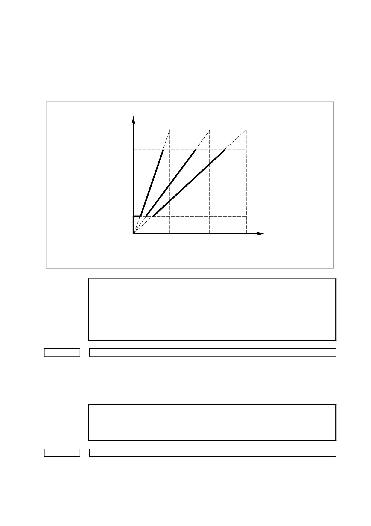
Set the maximum spindle speed corresponding to each gear.
Spindle motor speed
Max. speed (4095, 10V)
Spindle motor max. clamp speed
(Parameter No.3736)
Spindle motor minimum clamp speed
(Parameter No.3735)
Spindle speed command
(S command)
Gear 1
Gear 2
Gear 3
Max. speed
Max. speed
Max. speed
(Parameter
(Parameter
(Parameter
No.3741)
No.3742)
No.3743)
NOTE
If a type-T gear shift scheme is selected for the M series (with the
constant surface speed control option installed or bit 4 (GTT) of
parameter No. 3706 = 1), parameter No. 3744 is usable also in the
M series.
Note, however, that, even in this case, only up to three main gear
stages are usable for rigid tapping.
3770
Axis as the calculation reference in constant surface speed control
[Input type] Parameter input
[Data type] Byte path
[Valid data range] 0 to Number of controlled axes
Set the axis as the calculation reference in constant surface speed control.
NOTE
When 0 is set, constant surface speed control is always applied to
the X-axis. In this case, specifying P in a G96 block has no effect
on the constant surface speed control.
3781
P code for selecting the spindle in multi-spindle control
[Input type] Parameter input
[Data type] Word spindle
[Valid data range] 0 to 32767
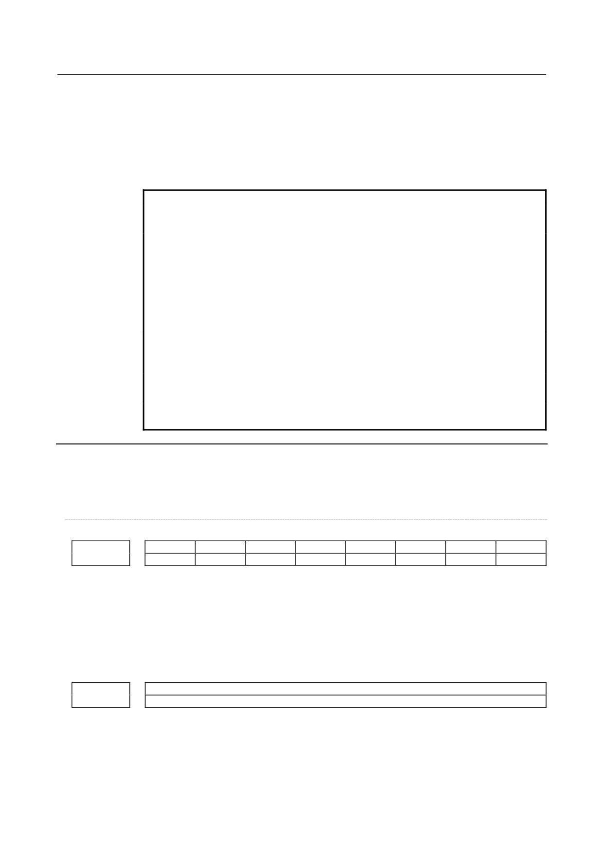
- 831 -
A.PARAMETERS
APPENDIX
B-64304EN/02
If bit 3 (MPP) of parameter No. 3703 is set to 1, set the P code to select each spindle
under multi-spindle control. Specify the P code in a block containing the S command.
Example)
If the P code value for selecting the second spindle is set to 3,
S1000 P3;
causes the second spindle to rotate at S1000.
NOTE
1 This parameter is valid if bit 3 (MPP) of parameter No. 3703 is set
to 1.
2 If this parameter is set to 0, the corresponding spindle cannot be
selected by a P code.
3 Under 2-path control, the P code specified here is valid for each
path.
For instance, if the P code to select the first spindle of path 2 is set
to 21, specifying S1000 P21; in path 1 causes the first spindle of
path 2 to be rotated at S1000.
4 Identical P code values cannot be used for different spindles.
(Identical P code values cannot be used even if the paths are
different.)
5 When this parameter is used (when bit 3 (MPP) of parameter No.
3703 is set to 1), the spindle command selection signal is invalid.
6 To use this parameter, enable multi-spindle control (bit 3 (MSP) of
parameter No. 8133 is 1).
Parameters Nos. 4000 to 4799 below are basically used with the serial spindle amplifier. For details of
these parameters, refer to either of the following manuals and other related documents, depending on the
spindle that is actually connected.
• FANUC AC SPINDLE MOTOR αi series Parameter Manual (B-65280EN)
#7
#6
#5
#4
#3
#2
#1
#0
FLRs
4900
[Input type] Parameter input
[Data type] Bit spindle
#0 FLRs When the spindle speed fluctuation detection function (T series) is used, the unit of an
allowable ratio (q) and fluctuation ratio (r) set by parameter No. 4911 and No. 4912 is:
0:
1%
1:
0.1%
Allowable speed ratio (q) used to assume that the spindle has reached a specified speed
4911
[Input type] Parameter input
[Data type] Word spindle
[Unit of data] 1%, 0.1%
[Valid data range] 1 to 100, 1 to 1000
When the spindle speed fluctuation detection function is used, set an allowable speed
ratio (q) used to assume that the spindle has reached a specified speed.
- 832 -
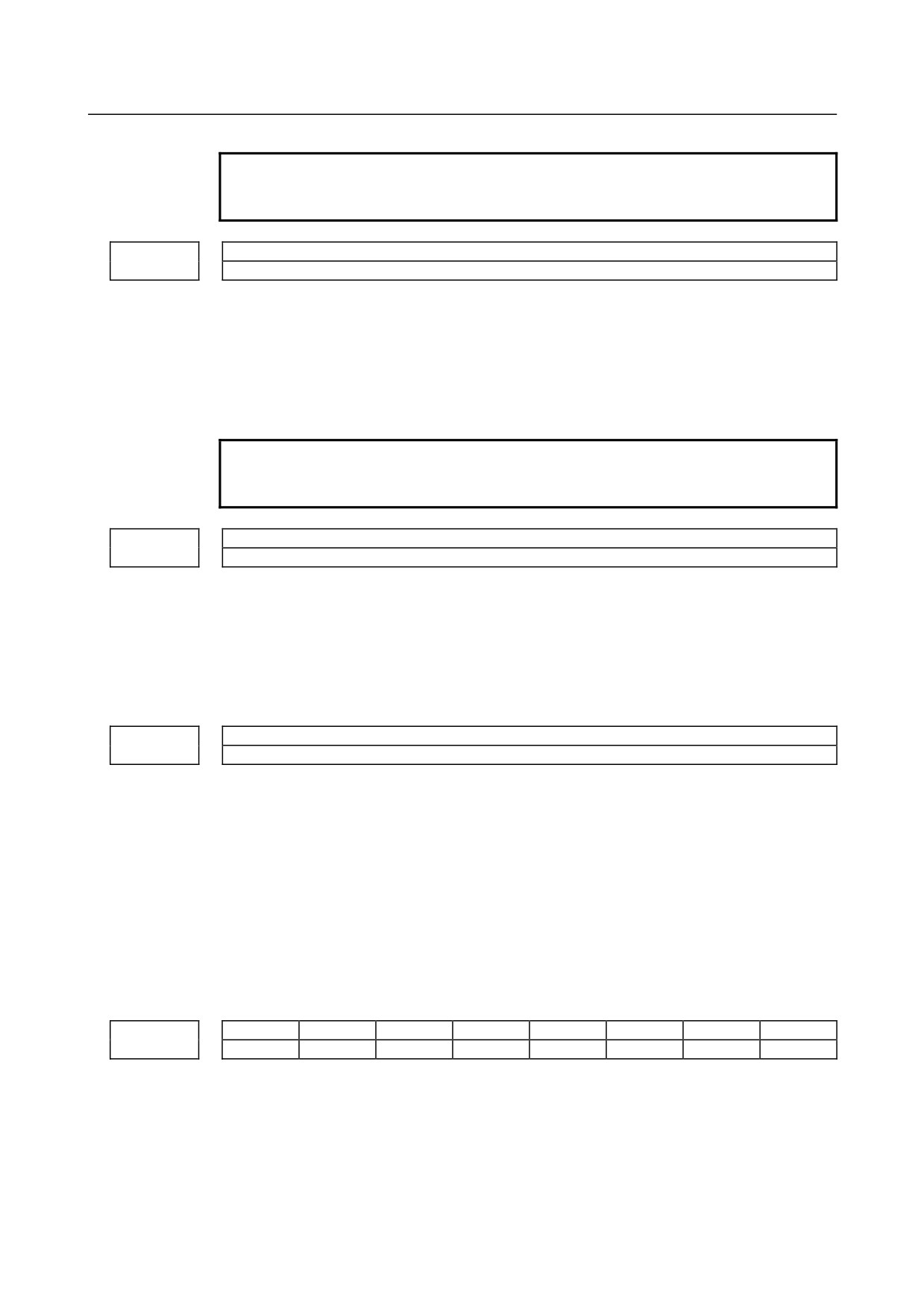
B-64304EN/02
APPENDIX
A.PARAMETERS
NOTE
The unit of data is determined by bit 0 (FLR) of parameter No.
4900.
Spindle variation ratio (r) for not issuing a spindle speed fluctuation detection alarm
4912
[Input type] Parameter input
[Data type] Word spindle
[Unit of data] 1%, 0.1%
[Valid data range] 1 to 100, 1 to 1000
When the spindle speed fluctuation detection function is used, set a spindle fluctuation
ratio (r) for not issuing an alarm.
NOTE
The unit of data is determined by bit 0 (FLR) of parameter No.
4900.
Spindle speed fluctuation width (i) for not issuing a spindle speed fluctuation detection alarm
4913
[Input type] Parameter input
[Data type] 2-word spindle
[Unit of data] min-1
[Valid data range] 0 to 99999
When the spindle speed fluctuation detection function is used, set an allowable
fluctuation width (i) for not issuing an alarm.
Time (p) from the change of a specified speed until spindle speed fluctuation detection is started
4914
[Input type] Parameter input
[Data type] 2-word spindle
[Unit of data] msec
[Valid data range] 0 to 999999
When the spindle speed fluctuation detection function is used, set a time (p) from the
change of a specified speed until spindle speed fluctuation detection is started. In other
words, spindle speed fluctuation detection is not performed until a set time has elapsed
after a specified speed is changed. However, when the actual spindle speed is assumed to
have reached a specified value within a set time (p), spindle speed fluctuation detection is
started.
#7
#6
#5
#4
#3
#2
#1
#0
ISZs
IDMs
IORs
4950
[Input type] Parameter input
[Data type] Bit spindle
#0 IORs Resetting the system in the spindle positioning mode
0: Does not release the mode.
1: Releases the mode
- 833 -
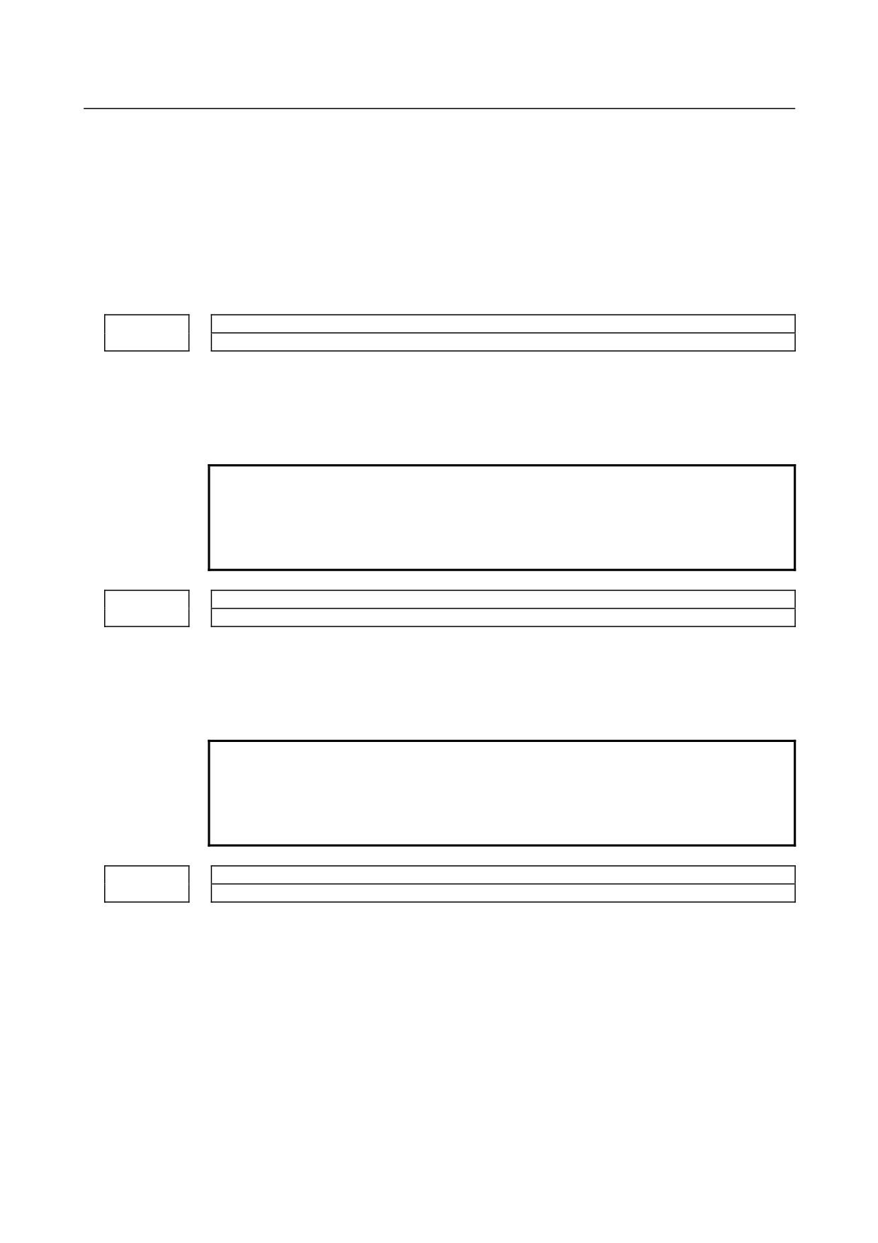
A.PARAMETERS
APPENDIX
B-64304EN/02
#1 IDMs The direction of spindle positioning (half-fixed angle positioning based on M codes) is:
0: Plus direction.
1: Minus direction.
#2 ISZs When an M code for spindle orientation is specified in spindle positioning:
0: The spindle is switched to the spindle positioning mode, and spindle orientation
operation is performed.
1: Only the switching of the spindle to the spindle positioning mode is performed.
(Spindle orientation operation is not performed.)
M code specifying the spindle orientation
4960
[Input type] Parameter input
[Data type] 2-word spindle
[Valid data range] 6 to 97
Set an M code for switching to the spindle positioning mode.
NOTE
1 Do not set an M code that duplicates other M codes used for
spindle positioning.
2 Do not set an M code used with other functions (such as M00-05,
30, 98, and 99, and M codes for calling subprograms).
M code releasing the spindle positioning mode
4961
[Input type] Parameter input
[Data type] 2-word spindle
[Valid data range] 6 to 97
Set an M code for canceling the spindle positioning mode on the spindle positioning axis.
NOTE
1 Do not set an M code that duplicates other M codes used for
spindle positioning.
2 Do not set an M code used with other functions (such as M00-05,
30, 98, and 99, and M codes for calling subprograms).
M code for specifying a spindle positioning angle
4962
[Input type] Parameter input
[Data type] 2-word spindle
[Valid data range] 6 to 9999999
Two methods are available for specifying spindle positioning. One method uses axis
address for arbitrary-angle positioning. The other use an M code for half-fixed angle
positioning. This parameter sets an M code for the latter method.
In this parameter, set an M code to be used for half-fixed angle positioning based on M
codes.
Six M code from Mα to M(α+5) are used for half-fixed angle positioning, when α is the
value of this parameter.
- 834 -
B-64304EN/02
APPENDIX
A.PARAMETERS
• When the number of M codes is set in parameter No. 4964, let α be the value set in
parameter No. 4962, and let β be the value set in parameter No. 4964. Then, β M
codes from Mα to M(α+β-1) are used as M codes for half-fixed angle positioning
based on M codes.
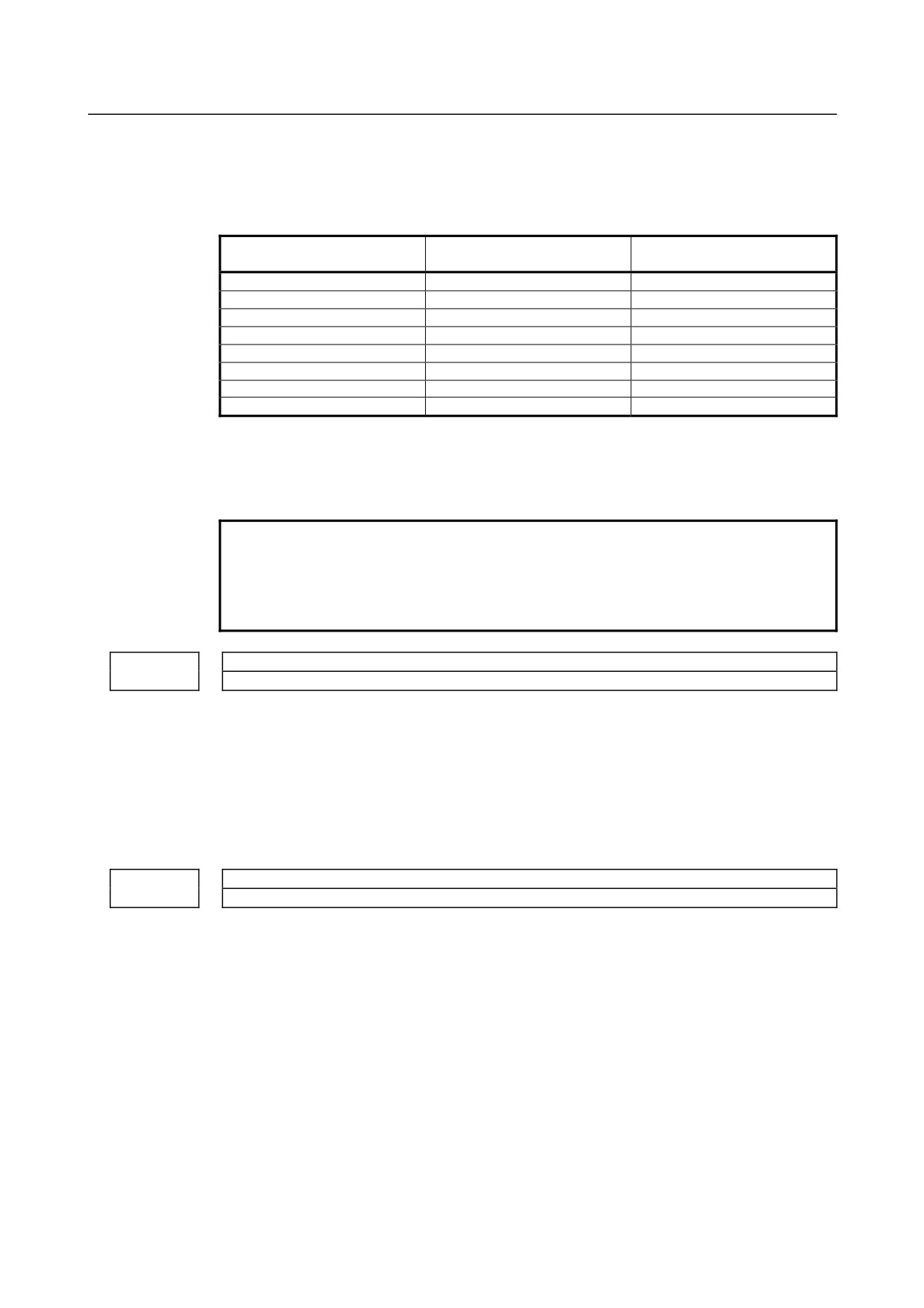
The table below indicates the relationship between the M codes and positioning angles.
Example: Positioning
M code
Positioning angle
angle when θ = 30°
Mα
θ
30°
M(α+1)
2θ
60°
M(α+2)
3θ
90°
M(α+3)
4θ
120°
M(α+4)
5θ
150°
M(α+5)
6θ
180°
:
:
:
M(α+β-1)
β×θ
β×30°
β represents the number of M codes set in parameter No. 4964.
(When parameter No. 4964 is set to 0, β = 6.)
θ represents the basic angular displacement set in parameter No.4963.
NOTE
1 Do not set an M code that duplicates other M codes used for
spindle positioning.
2 Do not set an M code used with other functions (such as M00-05,
30, 98, and 99, and M codes for calling subprograms).
Basic angle for half-fixed angle positioning
4963
[Input type] Parameter input
[Data type] Real spindle
[Unit of data] Degree
[Min. unit of data] Depend on the increment system of the applied axis
[Valid data range] 0 to 60
This parameter sets a basic angular displacement used for half-fixed angle positioning
using M codes.
Number of M codes for specifying a spindle positioning angle
4964
[Input type] Parameter input
[Data type] 2-word spindle
[Valid data range] 0 to 255
This parameter sets the number of M codes used for Half-fixed angle positioning using M
codes.
As many M codes as the number specified in this parameter, starting with the M code
specified in parameter No.4962, are used to specify half-fixed angle positioning.
Let α be the value of parameter No.4962, and let β be the value of parameter No.4964.
That is, M codes from Mα to M(α+β-1) are used for half-fixed angle positioning.
Setting this parameter to 0 has the same effect as setting 6. That is, M code from Mα to
M(α+5) are used for half-fixed angle positioning.
- 835 -
A.PARAMETERS
APPENDIX
B-64304EN/02
NOTE
1 Make sure that M codes from Mα to M (α+β-1) do not duplicate
other M codes.
2 Do not set an M code that duplicates other M codes used for
spindle positioning.
3 Do not set an M code used with other functions (such as M00-05,
30, 98, and 99, and M codes for calling subprograms).
#7
#6
#5
#4
#3
#2
#1
#0
5001
EVO
TAL
TLB
TLC
[Input type] Parameter input
[Data type] Bit path
#0 TLC
#1 TLB These bits are used to select a tool length compensation type.
Type
TLB
TLC
Tool length compensation A
0
0
Tool length compensation B
1
0
Tool length compensation C
-
1
The axis to which cutter compensation is applied varies from type to type as described
below.
Tool length compensation A :
Z-axis at all times
Tool length compensation B :
Axis perpendicular to a specified plane (G17/G18/G19)
Tool length compensation C :
Axis specified in a block that specifies G43/G44
#3 TAL Tool length compensation C
0: Generates an alarm when two or more axes are offset
1: Not generate an alarm even if two or more axes are offset
#6 EVO If a tool compensation value modification is made for tool length compensation A or tool
length compensation B in the offset mode (G43 or G44):
0: The new value becomes valid in a block where G43, G44, or an H code is specified
next.
1: The new value becomes valid in a block where buffering is performed next.
#7
#6
#5
#4
#3
#2
#1
#0
LWT
LGN
5002
[Input type] Parameter input
[Data type] Bit path
#1 LGN Geometry offset number of tool offset
0: Is the same as wear offset number
1: Specifies the geometry offset number by the tool selection number
- 836 -
B-64304EN/02
APPENDIX
A.PARAMETERS
NOTE
This parameter is valid when tool geometry/wear compensation is
enabled (bit 6 (NGW) of parameter No. 8136 is 0).
#2 LWT Tool wear compensation is performed by:
0: Moving the tool.
1: Shifting the coordinate system.
NOTE
This parameter is valid when tool geometry/wear compensation is
enabled (bit 6 (NGW) of parameter No. 8136 is 0).
#7
#6
#5
#4
#3
#2
#1
#0
5003
SUV
SUP
[Input type] Parameter input
[Data type] Bit path
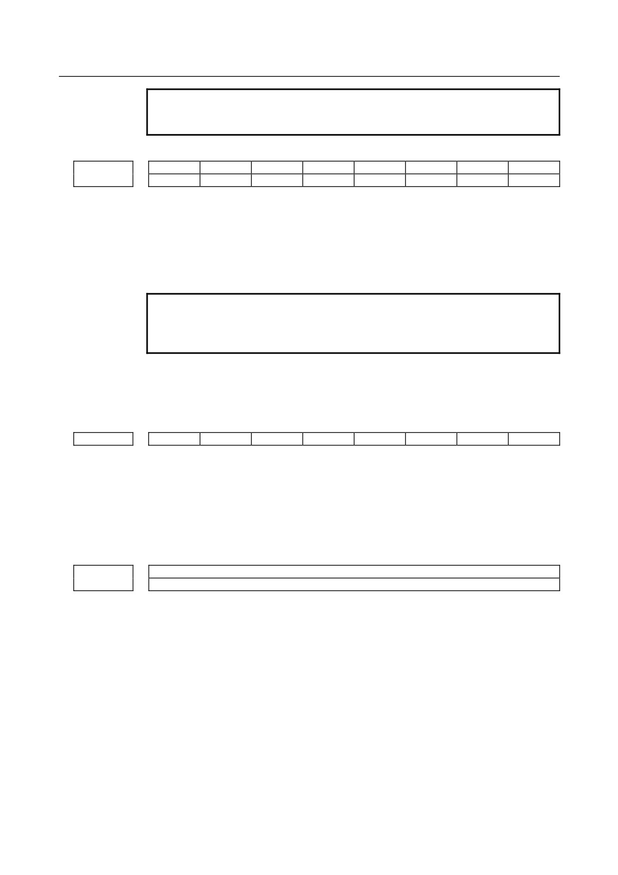
#0 SUP
#1
SUV These bits are used to specify the type of startup/cancellation of cutter compensation or
tool nose radius compensation.
SUV
SUP
Type
Operation
0
0
Type A
A compensation vector perpendicular to the block next to the startup block or
the block preceding the cancellation block is output.
Tool nose radius center path /
G41
Tool center path
Programmed path
N2
N1
0
1
Type B
A compensation vector perpendicular to the startup block or cancellation block
and an intersection vector are output.
Intersection point
Tool nose radius center path /
Tool center path
Programmed path
G41
N2
N1
1
0
Type C
When the startup block or cancellation block specifies no movement
1
operation, the tool is shifted by the cutter compensation amount in a direction
perpendicular to the block next to the startup or the block before cancellation
block.
Intersection point
Tool nose radius center path /
G41
Tool center path
Shift
Programmed path
N3
N2
When the block specifies movement operation, the type is set according to the
SUP setting; if SUP is 0, type A is set, and if SUP is 1, type B is set.
- 837 -
A.PARAMETERS
APPENDIX
B-64304EN/02
NOTE
When SUV,SUP = 0,1 (type B), an operation equivalent to that of
FS0i-TC is performed.
#7
#6
#5
#4
#3
#2
#1
#0
ORC
5004
ODI
[Input type] Parameter input
[Data type] Bit path
#1 ORC The setting of a tool offset value is corrected as:
0: Diameter value
1: Radius value
NOTE
This parameter is valid only for an axis based on diameter
specification. For an axis based on radius specification, specify a
radius value, regardless of the setting of this parameter.
#2 ODI The setting of a cutter compensation value is corrected as:
0: Radius value
1: Diameter value
#7
#6
#5
#4
#3
#2
#1
#0
5008
MCR
[Input type] Parameter input
[Data type] Bit path
#4 MCR If G41/G42 (cutter compensation or tool nose radius compensation) is specified in the
MDI mode, an alarm is:
0: Not raised.
1: Raised. (alarm PS5257)
Number of digits of an offset number used with a T code command
5028
[Input type] Parameter input
[Data type] Byte path
[Valid data range] 0 to 3
Specify the number of digits of a T code portion that is used for a tool offset number
(wear offset number when the tool geometry/wear compensation function is used).
When 0 is set, the number of digits is determined by the number of tool compensation
values.
When the number of tool compensation values is 1 to 9: Lower 1 digit
When the number of tool compensation values is 10 to 99: Lower 2 digits
When the number of tool compensation values is 100 to 200: Lower 3 digits
Example :
When an offset number is specified using the lower 2 digits of a T code, set 2 in
parameter No. 5028.
Txxxxxx yy
xxxxxx : Tool selection
yy : Tool offset number
- 838 -
B-64304EN/02
APPENDIX
A.PARAMETERS
NOTE
A value longer than the setting of parameter No. 3032 (allowable
number of digits of a T code) cannot be set.
5029
Number of tool compensation value memories common to paths
NOTE
When this parameter is set, the power must be turned off before
operation is continued.
[Input type] Parameter input
[Data type] Word
[Valid data range] 0 to number of tool compensation values
When using memories common to paths, set the number of common tool compensation
values in this parameter.
Ensure that the setting of this parameter does not exceed the number of tool compensation
values set for each path (parameter No. 5024).
[Example 1]
When parameter No. 5029 = 10, parameter No. 5024 (path 1) = 15, and parameter
No. 5024 (path 2) = 30 in a 2-path system, tool compensation numbers 1 to 10 of all
paths are made common.
[Example 2]
When parameter No. 5029 = 20 and the other conditions are the same as for
Example 1, tool compensation numbers 1 to 15 are made common.
NOTE
1 Ensure that the setting of parameter No. 5029 does not exceed the
number of tool compensation values for each path (parameter No.
5024). If the setting of parameter No. 5029 exceeds the number of
compensation values of a path, the least of the numbers of
compensation values in all paths is made common.
2 When 0 or a negative value is set, memories common to paths are
not used.
#7
#6
#5
#4
#3
#2
#1
#0
OWD
5040
[Input type] Parameter input
[Data type] Bit path
#0 OWD In radius programming (bit 1 (ORC) of parameter No. 5004 is set to 1),
0: Tool offset values of both geometry compensation and wear compensation are
specified by radius.
1: Tool offset value of geometry compensation is specified by radius and tool offset
value of wear compensation is specified by diameter, for an axis of diameter
programming.
- 839 -
A.PARAMETERS
APPENDIX
B-64304EN/02
NOTE
This parameter is valid when tool geometry/wear compensation is
enabled (bit 6 (NGW) of parameter No. 8136 is 0).
#7
#6
#5
#4
#3
#2
#1
#0
5042
OFC
OFA
[Input type] Parameter input
[Data type] Bit path
NOTE
When at least one of these parameters is set, the power must be
turned off before operation is continued.
#0 OFA
#1 OFC These bits are used to specify the increment system and valid data range of a tool offset
value.
For metric input
OFC
OFA
Unit
Valid data range
0
1
0.01mm
±9999.99mm
0
0
0.001mm
±9999.999mm
1
0
0.0001mm
±9999.9999mm
For inch input
OFC
OFA
Unit
Valid data range
0
1
0.001inch
±999.999inch
0
0
0.0001inch
±999.9999inch
1
0
0.00001inch
±999.99999inch
Axis number for which Y-axis offset is used
5043
[Input type] Parameter input
[Data type] Byte path
[Valid data range] 0 to Number of controlled axes
Set the number of an axis for which the tool offset is corrected.
If 0 or a value beyond the valid data range is set, the Y-axis offset is applied to the Y-axis
of the basic three axes. If setting is made for the X- or Z-axis of the basic three axes, the
standard tool offset for the X- or Z-axis is not used, and only the Y-axis offset is used.
#7
#6
#5
#4
#3
#2
#1
#0
5101
FXY
[Input type] Parameter input
[Data type] Bit path
- 840 -
B-64304EN/02
APPENDIX
A.PARAMETERS
#0 FXY The drilling axis in the drilling canned cycle, or cutting axis in the grinding canned cycle
is:
0: In case of the Drilling canned cycle:
Z-axis at all times.
In case of the Grinding canned cycle:
• For the T series
Z-axis at all times.
• For the M series
G75,G77 command :Y-axis
G78,G79 command :Z-axis
1: Axis selected by the program
NOTE
1 In the case of the T series, this parameter is valid only for the
drilling canned cycle in the Series 10/11 format.
2 When this parameter is 1, the drilling axis determined by plane
selection (G17/G18/G19) in the drilling canned cycle in the T series
10/11 format. Therefore, the Y-axis is required to specify
G17/G19.
#7
#6
#5
#4
#3
#2
#1
#0
GFX
5106
[Input type] Parameter input
[Data type] Bit path
NOTE
When this parameter is set, the power must be turned off before
operation is continued.
#0 GFX When grinding canned cycle option is specified, the G71, G72, G73, or G74 command is:
0: A multiple repetitive canned cycle (T series) command.
1: A grinding canned cycle command.
Grinding axis number in Traverse Grinding Cycle(G71)
5176
Grinding axis number in Plunge Grinding Cycle(G75)
[Input type] Parameter input
[Data type] Byte path
[Valid data range] 0 to Number of controlled axes
For the Lathe system:
Set the Grinding axis number of Traverse Grinding Cycle(G71).
For the Machining Center system:
Set the Grinding axis number of Plunge Grinding Cycle(G75).
NOTE
The axis number except for the cutting axis can be specified. When
the axis number which is same to cutting axis is specified, PS0456
alarm is issued at the time of execution. The Grinding Cycle is
executed when this parameter value is 0, PS0456 alarm is also
issued.
- 841 -
A.PARAMETERS
APPENDIX
B-64304EN/02
Grinding axis number of Traverse direct constant-size Grinding cycle(G72)
5177
Grinding axis number of Direct Constant Dimension Plunge Grinding Cycle(G77)
[Input type] Parameter input
[Data type] Byte path
[Valid data range] 0 to Number of controlled axes
For the Lathe system:
Set the Grinding axis number of Traverse direct constant-size Grinding cycle(G72).
For the Machining Center system:
Set the Grinding axis number of Direct Constant Dimension Plunge Grinding Cycle
(G77).
NOTE
The axis number except for the cutting axis can be specified. When
the axis number which is same to cutting axis is specified, PS0456
alarm is issued at the time of execution. The Grinding Cycle is
executed when this parameter value is 0, PS0456 alarm is also
issued.
Grinding axis number of Oscillation Grinding Cycle(G73)
5178
Grinding axis number of Continuous feed surface grinding cycle(G78)
[Input type] Parameter input
[Data type] Byte path
[Valid data range] 0 to Number of controlled axes
For the Lathe system:
Set the Grinding axis number of Oscillation Grinding Cycle(G73).
For the Machining Center system:
Set the Grinding axis number of Continuous feed surface grinding cycle(G78).
NOTE
The axis number except for the cutting axis can be specified. When
the axis number which is same to cutting axis is specified, PS0456
alarm is issued at the time of execution. The Grinding Cycle is
executed when this parameter value is 0, PS0456 alarm is also
issued.
Grinding axis number of Oscillation Direct Fixed Dimension Grinding Cycle(G74)
5179
Grinding axis number of Intermittent feed surface grinding cycle(G79)
[Input type] Parameter input
[Data type] Byte path
[Valid data range] 0 to Number of controlled axes
For the Lathe system:
Set the Grinding axis number of Oscillation Direct Fixed Dimension Grinding
Cycle(G74).
For the Machining Center system:
Set the Grinding axis number of Intermittent feed surface grinding cycle(G79).
- 842 -
B-64304EN/02
APPENDIX
A.PARAMETERS
NOTE
The axis number except for the cutting axis can be specified. When
the axis number which is same to cutting axis is specified, PS0456
alarm is issued at the time of execution. The Grinding Cycle is
executed when this parameter value is 0, PS0456 alarm is also
issued.
5180
Axis number of dressing axis in Plunge grinding cycle(G75)
[Input type] Parameter input
[Data type] Byte path
[Valid data range] 0 to Number of controlled axes
Set the axis number of dressing axis in Plunge grinding cycle(G75).
NOTE
The axis number except for the cutting axis or grinding axis can be
specified. When the axis number which is same to cutting axis or
grinding axis is specified, PS0456 alarm is issued at the time of
execution. The Grinding Cycle is executed when this parameter
value is 0 and address "L" is specified in NC program, the PS0456
alarm is also issued.
5181
Axis number of dressing axis in Direct constant dimension plunge grinding cycle(G77)
[Input type] Parameter input
[Data type] Byte path
[Valid data range] 0 to Number of controlled axes
Set the axis number of dressing axis in Direct constant dimension plunge grinding
cycle(G77).
NOTE
The axis number except for the cutting axis or grinding axis can be
specified. When the axis number which is same to cutting axis or
grinding axis is specified, PS0456 alarm is issued at the time of
execution. The Grinding Cycle is executed when this parameter
value is 0 and address "L" is specified in NC program, the PS0456
alarm is also issued.
5182
Axis number of dressing axis in Continuous feed surface grinding cycle(G78)
[Input type] Parameter input
[Data type] Byte path
[Valid data range] 0 to Number of controlled axes
Set the axis number of dressing axis in Continuous feed surface grinding cycle(G78).
- 843 -
A.PARAMETERS
APPENDIX
B-64304EN/02
NOTE
The axis number except for the cutting axis or grinding axis can be
specified. When the axis number which is same to cutting axis or
grinding axis is specified, PS0456 alarm is issued at the time of
execution. The Grinding Cycle is executed when this parameter
value is 0 and address "L" is specified in NC program, the PS0456
alarm is also issued.
5183
Axis number of dressing axis in Intermittent feed surface grinding cycle(G79)
[Input type] Parameter input
[Data type] Byte path
[Valid data range] 0 to Number of controlled axes
Set the axis number of dressing axis in Intermittent feed surface grinding cycle(G79).
NOTE
The axis number except for the cutting axis or grinding axis can be
specified. When the axis number which is same to cutting axis or
grinding axis is specified, PS0456 alarm is issued at the time of
execution. The Grinding Cycle is executed when this parameter
value is 0 and address "L" is specified in NC program, the PS0456
alarm is also issued.
#7
#6
#5
#4
#3
#2
#1
#0
5200
CRG
G84
[Input type] Parameter input
[Data type] Bit path
#0 G84 Method for specifying rigid tapping:
0: An M code specifying the rigid tapping mode is specified prior to the issue of the
G84 (or G74) command. (See parameter No.5210).
1: An M code specifying the rigid tapping mode is not used. (G84 cannot be used as a
G code for the tapping cycle; G74 cannot be used for the reverse tapping cycle.)
#2 CRG Rigid mode when a rigid mode cancel command is specified (G80, G01 group G code,
reset, etc.) :
0: Canceled after rigid tapping signal RGTAP is set to "0".
1: Canceled before rigid tapping signal RGTAP is set to "0".
5241
Maximum spindle speed in rigid tapping (first gear)
5242
Maximum spindle speed in rigid tapping (second gear)
5243
Maximum spindle speed in rigid tapping (third gear)
Maximum spindle speed in rigid tapping (fourth gear)
5244
[Input type] Parameter input
[Data type] 2-word spindle
[Unit of data] min-1
- 844 -
B-64304EN/02
APPENDIX
A.PARAMETERS
[Valid data range] 0 to 9999
Spindle position coder gear ratio
1 : 1
0 to 7400
1 : 2
0 to 9999
1 : 4
0 to 9999
1 : 8
0 to 9999
Each of these parameters is used to set a maximum spindle speed for each gear in rigid
tapping.
Set the same value for both parameter No.5241 and parameter No.5243 for a one-stage
gear system. For a two-stage gear system, set the same value as set in parameter No. 5242
in parameter No. 5243. Otherwise, alarm PS0200 will be issued. This applies to the M
series.
#7
#6
#5
#4
#3
#2
#1
#0
5400
SCR
XSC
[Input type] Parameter input
[Data type] Bit path
#6 XSC The setting of a scaling magnification (axis-by-axis scaling) is:
0: Disabled.
1: Enabled.
#7 SCR Scaling (G51) magnification unit:
0:
0.00001 times (1/100,000)
1:
0.001 times
#7
#6
#5
#4
#3
#2
#1
#0
5401
SCLx
[Input type] Parameter input
[Data type] Bit axis
#0 SCLx Scaling on this axis:
0: Invalidated
1: Validated
5411
Scaling (G51) magnification
[Input type] Setting input
[Data type] 2-word path
[Unit of data] 0.001 or 0.00001 times (Selected using SCR, #7 of parameter No.5400)
[Valid data range] 1to999999999
This parameter sets a scaling magnification when axis-by-axis scaling is disabled (with
bit 6 (XSC) of parameter No. 5400 set to 0). If no scaling magnification (P) is specified in
the program, the setting of this parameter is used as a scaling magnification.
NOTE
When bit 7 (SCR) of parameter No.5400 is set to 1, the valid data
range is 1 to 9999999.
- 845 -