FANUC Series 0i-MODEL D, Series 0i Mate-MODEL D. OPERATOR'S MANUAL - page 28
A.PARAMETERS
APPENDIX
B-64304EN/02
F
axi
ΔF = m
(where, i=1 or 2)
100n
In the above equation, set n. That is, the number of revolutions
of the manual pulse generator, required to reach feedrate Fmaxi is obtained. Fmaxi refers
to the upper limit of the feedrate for a one-digit F code feed command, and set it in
parameters No. 1460 or No. 1461.
Fmax1: Upper limit of the feedrate for F1 to F4 (parameter No. 1460)
Fmax2: Upper limit of the feedrate for F5 to F9 (parameter No. 1461)
1451
Feedrate for F1
to
to
1459
Feedrate for F9
[Input type] Setting input
[Data type] Real path
[Unit of data] mm/min, inch/min, degree/min (machine unit)
[Min. unit of data] Depend on the increment system of the reference axis
[Valid data range] Refer to the standard parameter setting table (C)
(When the increment system is IS-B, 0.0 to +999000.0)
These parameters set the feedrates for one-digit F code feed commands F1 to F9. When a
one-digit F code feed command is specified, and the feedrate is changed by turning the
manual pulse generator, the parameter-set value also changes accordingly.
1460
Upper limit of feedrate for F1 to F4
1461
Upper limit of feedrate for F5 to F9
[Input type] Parameter input
[Data type] Real path
[Unit of data] mm/min, inch/min, degree/min (machine unit)
[Min. unit of data] Depend on the increment system of the reference axis
[Valid data range] Refer to the standard parameter setting table (C)
(When the increment system is IS-B, 0.0 to +999000.0)
Set the upper limit of feedrate for the one-digit F code feed command.
As the feedrate increases by turning the manual pulse generator, the feedrate is clamped
when it reaches the upper limit set. If a one-digit F feed command F1 to F4 is executed,
the upper limit is that set in parameter No. 1460. If a one-digit F code feed command F5
to F9 is executed, the upper limit is that set in parameter No. 1461.
1465
Radius of a virtual circle when a feedrate is specified on the virtual circle of a rotation axis
[Input type] Parameter input
[Data type] Real axis
[Unit of data] mm, inch (input unit)
[Min. unit of data] Depend on the increment system of the applied axis
[Valid data range] Refer to the standard parameter setting table (B)
Set the radius of a virtual circle when a feedrate on the virtual circle of a rotation axis is
specified.
If 0 is set for a rotation axis, the axis is excluded from feedrate calculation.
If the input unit is the inch, enter a value in inches.
- 786 -
B-64304EN/02
APPENDIX
A.PARAMETERS
The data is then converted to a millimeter value and displayed.
NOTE
1 This parameter is valid when bit 0 (ROTx) of parameter No. 1006
and bit 0 (RFDx) of parameter No. 1408 are 1.
2 Be careful to set bit 0 (RFDx) of parameter No. 1408 and
parameter No. 1465 for the virtual radius. If the virtual radius is
set to a small value and a feedrate on the virtual circle of the
rotation axis is specified, the movement of the axis becomes faster.
#7
#6
#5
#4
#3
#2
#1
#0
1601
NCI
[Input type] Parameter input
[Data type] Bit path
#5 NCI An in-position check:
0: Confirms that the specified feedrate becomes 0 (the acceleration/deceleration delay
becomes 0) at deceleration time and that the machine position has reached a
specified position (the servo positional deviation is within the in-position width set
by parameter No. 1826).
1: Confirms only that the specified feedrate becomes 0 (the acceleration/deceleration
delay becomes 0) at deceleration time.
#7
#6
#5
#4
#3
#2
#1
#0
1606
MNJx
[Input type] Parameter input
[Data type] Bit axis
#0 MNJx In manual handle interrupt :
0: Only cutting feed acceleration/deceleration is enabled, and jog feed
acceleration/deceleration is disabled.
1: Both cutting feed acceleration/deceleration and jog feed acceleration/deceleration
are applied.
#7
#6
#5
#4
#3
#2
#1
#0
1610
CTBx
CTLx
[Input type] Parameter input
[Data type] Bit axis
#0 CTLx Acceleration/deceleration in cutting feed or dry run
0: Exponential acceleration/deceleration is applied.
1: Linear acceleration/deceleration after interpolation is applied.
- 787 -
A.PARAMETERS
APPENDIX
B-64304EN/02
NOTE
When using bell-shaped acceleration/deceleration after
interpolation, set this parameter to 0 and set bit 1 (CTBx) of
parameter No. 1610 to select bell-shaped acceleration/deceleration
after interpolation.
Parameter
Acceleration/deceleration
CTBx
CTLx
0
0
Exponential acceleration/deceleration after interpolation
0
1
Linear acceleration/deceleration after interpolation
1
0
Bell-shaped acceleration/deceleration after interpolation
#1 CTBx Acceleration/deceleration in cutting feed or dry run
0: Exponential acceleration/deceleration or linear acceleration/ deceleration is applied.
(depending on the setting in CTLx, bit 0 of parameter No.1610)
1: Bell-shaped acceleration/deceleration is applied.
NOTE
This parameter is valid only when the bell-shaped
acceleration/deceleration after cutting feed interpolation function is
used. When this function is not used, the
acceleration/deceleration is determined according to bit 0 (CTLx) of
parameter No. 1610 regardless of the setting of this parameter.
Time constant T or T1 used for linear acceleration/deceleration or bell-shaped acceleration/deceleration
1620
in rapid traverse for each axis
[Input type] Parameter input
[Data type] Word axis
[Unit of data] msec
[Valid data range] 0 to 4000
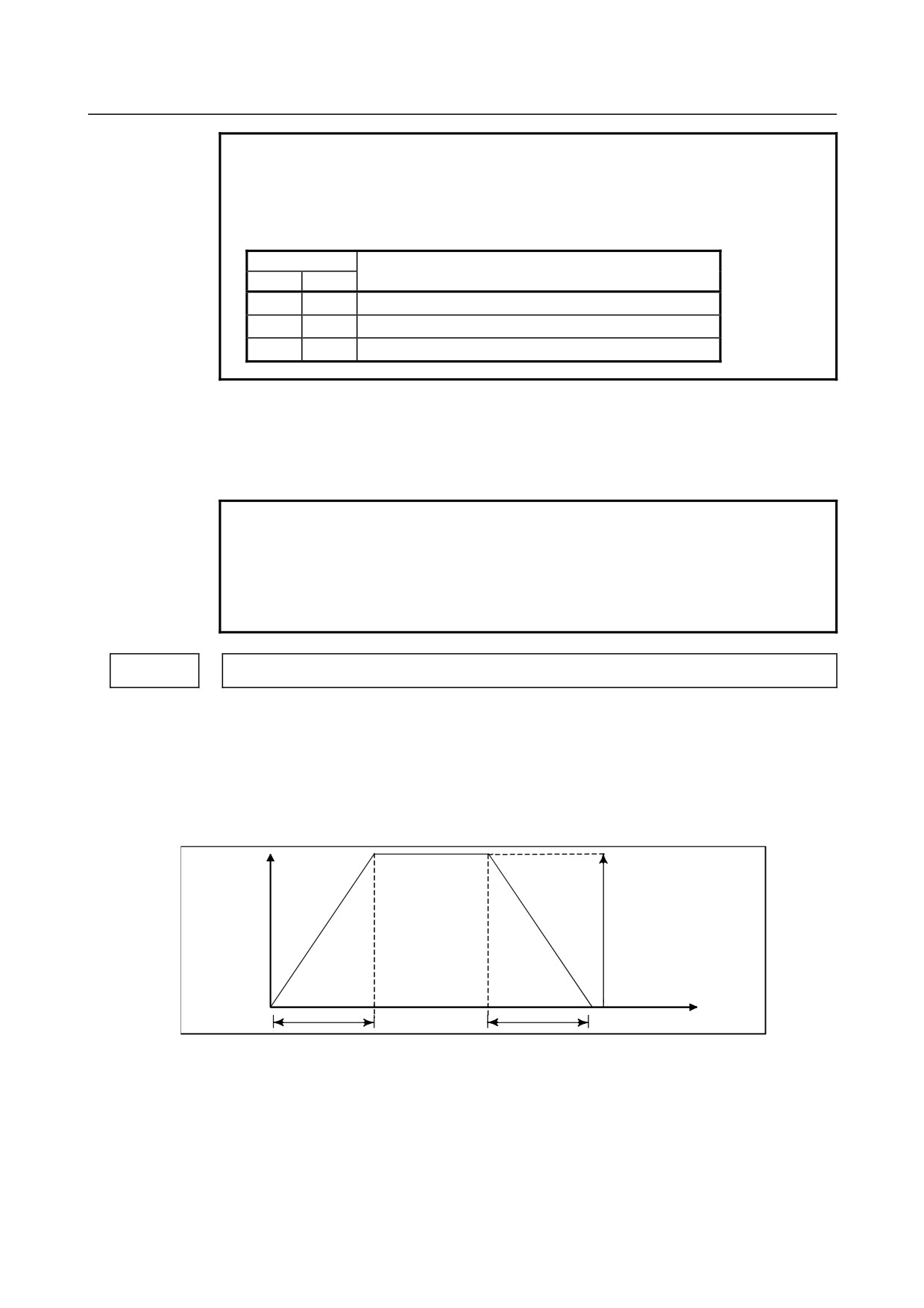
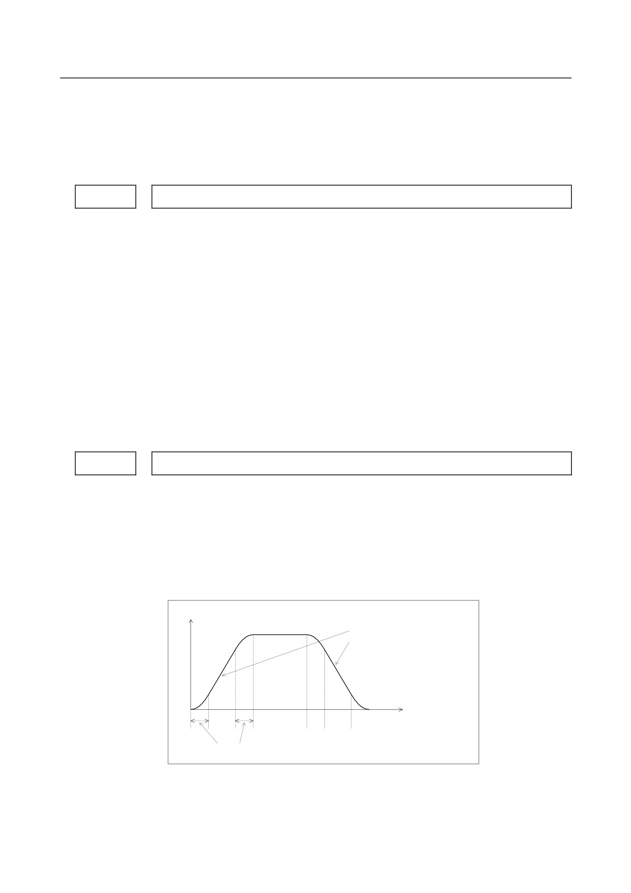
Specify a time constant used for acceleration/deceleration in rapid traverse.
[Example]
For linear acceleration/deceleration
Speed
Rapid traverse rate
(Parameter No. 1420)
T
T
Time
T : Setting of parameter No. 1620
- 788 -
B-64304EN/02
APPENDIX
A.PARAMETERS
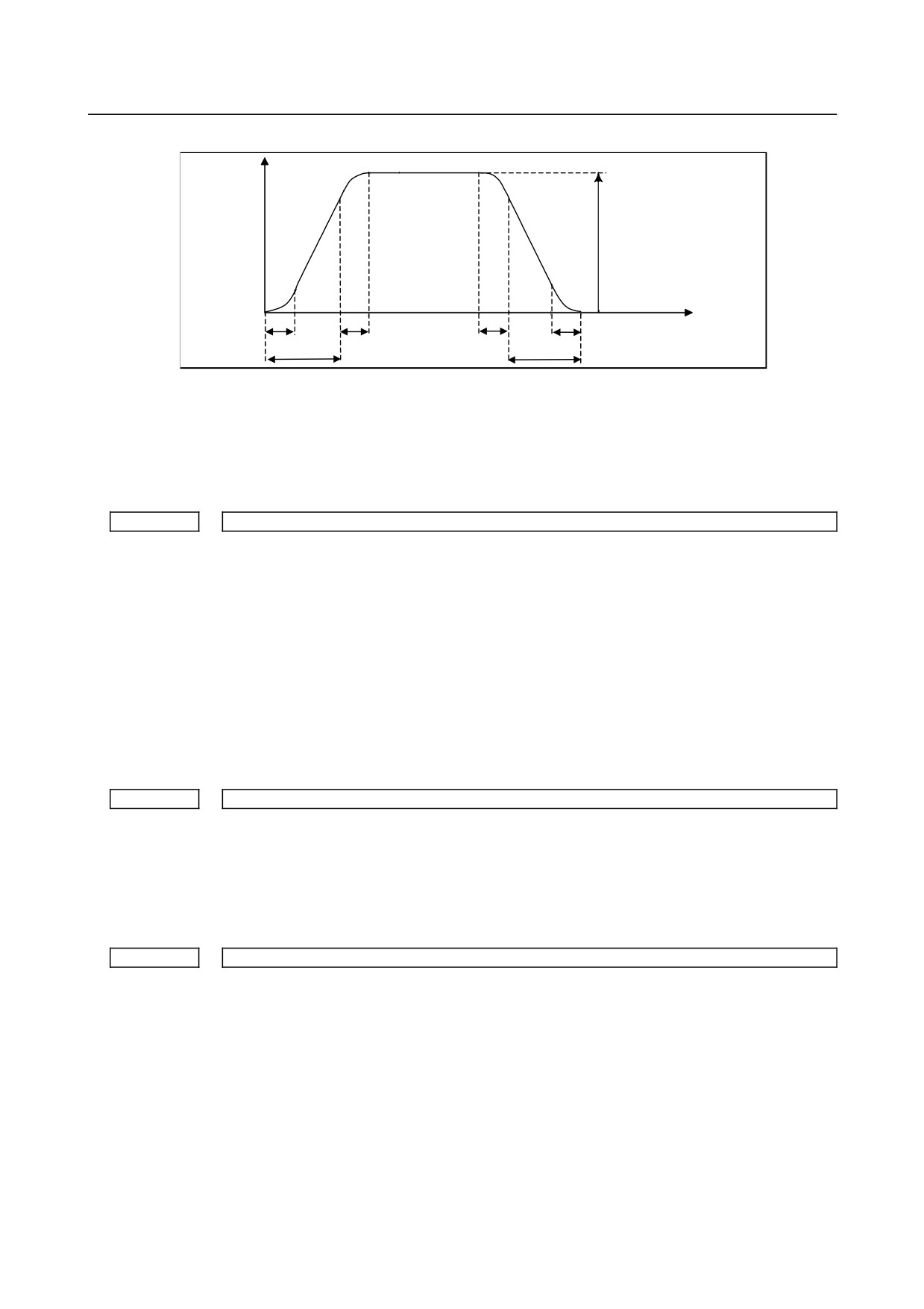
For bell-shaped acceleration/deceleration
Speed
Rapid traverse rate
(Parameter No. 1420)
T2
T2
T2
T2
Time
T1
T1
T1
: Setting of parameter No. 1620
T2
: Setting of parameter No. 1621
(However, T1 ≥ T2 must be satisfied.)
Total acceleration (deceleration) time : T1 + T2
Time for linear portion
: T1−T2
Time for curve portion
: T2 × 2
1622
Time constant of acceleration/deceleration in cutting feed for each axis
[Input type] Parameter input
[Data type] Word axis
[Unit of data] msec
[Valid data range] 0 to 4000
Set the time constant used for exponential acceleration/deceleration in cutting feed,
bell-shaped
acceleration/deceleration
after
interpolation
or
linear
acceleration/deceleration after interpolation in cutting feed for each axis. Which type to
use is selected with bits 1(CTBx) and 0(CTLx) of parameter No.1610. Except for special
applications, the same time constant must be set for all axes in this parameter. If the time
constants set for the axes differ from each other, proper straight lines and arcs cannot be
obtained.
1624
Time constant of acceleration/deceleration in jog feed for each axis.
[Input type] Parameter input
[Data type] Word axis
[Unit of data] msec
[Valid data range] 0 to 4000
Set the time constant used for acceleration/deceleration in jog feed for each axis.
1660
Maximum allowable acceleration rate in acceleration/deceleration before interpolation for each axis
[Input type] Parameter input
[Data type] Real axis
[Unit of data] mm/sec2, inch/sec2, degree/sec2 (machine unit)
[Min. unit of data] Depend on the increment system of the applied axis
[Valid data range] Refer to the standard parameter setting table (D)
(When the machine system is metric system, 0.0 to +100000.0. When the machine system
is inch system, machine, 0.0 to +10000.0.)
Set a maximum allowable acceleration rate in acceleration/ deceleration before
interpolation for each axis.
If a value greater than 100000.0 is set, the value is clamped to 100000.0.
- 789 -
A.PARAMETERS
APPENDIX
B-64304EN/02
If 0 is set, the specification of 100000.0 is assumed. If 0 is set for all axes, however,
acceleration/deceleration before interpolation is not performed.
If a maximum allowable acceleration rate set for one axis is greater than a maximum
allowable acceleration rate set for another axis by a factor or 2 or more, the feedrate at a
corner where the direction of travel abruptly changes can decrease temporarily.
Maximum allowable acceleration rate in acceleration/deceleration before interpolation for linear rapid
1671
traverse for each axis
[Input type] Parameter input
[Data type] Real axis
[Unit of data] mm/sec2, inch/sec2, degree/sec2 (machine unit)
[Min. unit of data] Depend on the increment system of the applied axis
[Valid data range] Refer to the standard parameter setting table (D)
(When the machine system is metric system, 0.0 to +100000.0. When the machine system
is inch system, machine, 0.0 to +10000.0.)
Set a maximum allowable acceleration rate in acceleration/ deceleration before
interpolation for linear rapid traverse.
If a value greater than 100000.0, the value is clamped to 100000.0.
If 0 is set, the specification of the following is assumed:
1000.0 mm/sec2
100.0 inch/sec2
100.0 degrees/sec2
If 0 is specified for all axes, however, acceleration/deceleration before interpolation is not
performed.
Acceleration change time of bell-shaped acceleration/deceleration before interpolation for linear rapid
1672
traverse
[Input type] Parameter input
[Data type] 2-word path
[Unit of data] msec
[Valid data range] 0 to 200
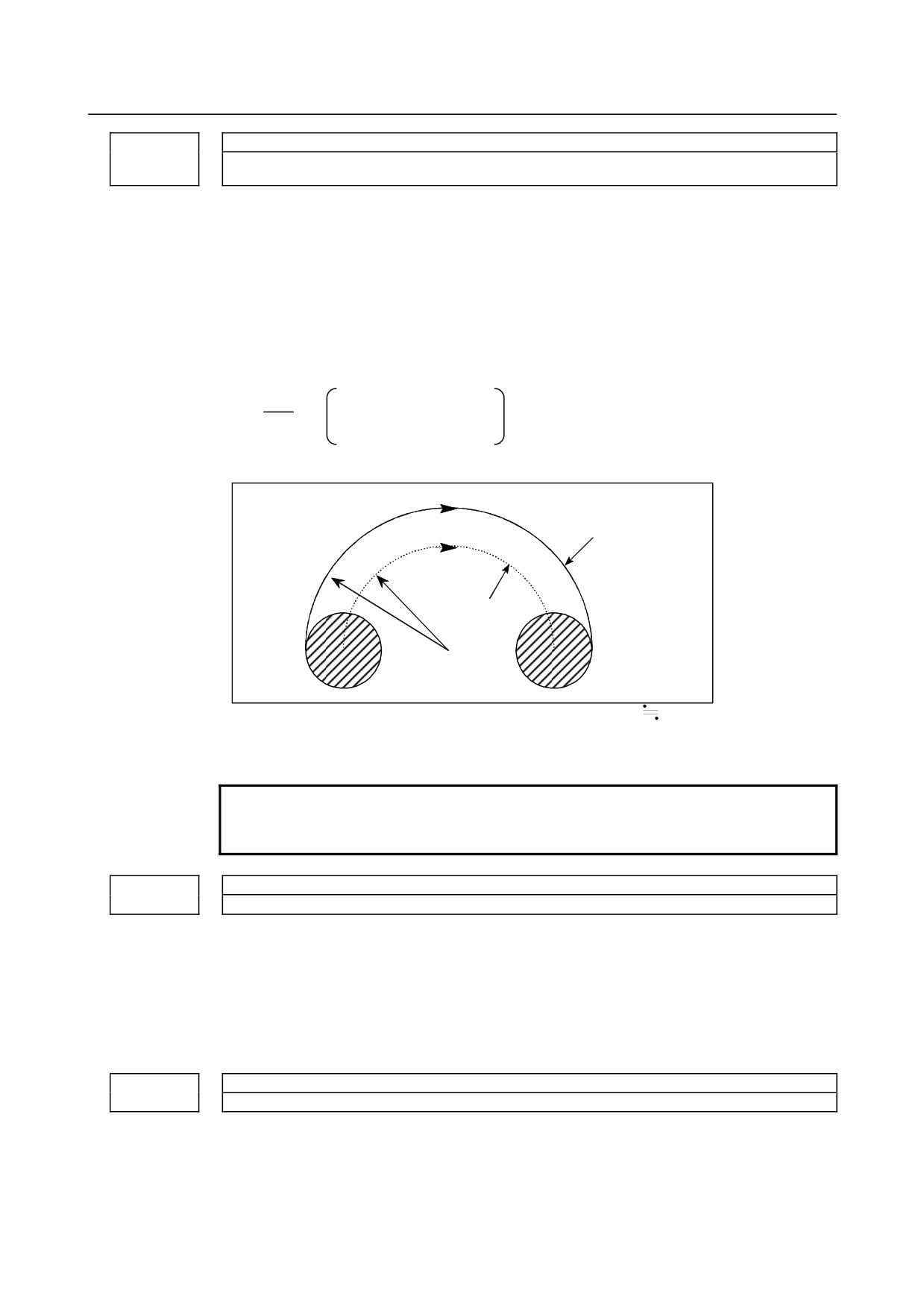
Set an acceleration change time of bell-shaped acceleration/ deceleration for linear rapid
traverse (time for changing from the state of constant feedrate (A) to the state of constant
acceleration/deceleration (C) at the acceleration rate calculated from the acceleration rate
set in parameter No. 1671: time of (B) in the figure below).
Feedrate in tangent direction
Maximum acceleration rate not exceeding
maximum allowable acceleration rate set by
parameter No.
1671 for each axis is
automatically calculated.
(A)
(B)
(C)
(B)
(A)
(B)
(C)
(B)
(A)
Tim e set by param eter No. 1672
- 790 -
B-64304EN/02
APPENDIX
A.PARAMETERS
1710
Minimum deceleration ratio (MDR) for inner circular cutting feedrate change by automatic corner
override
[Input type] Parameter input
[Data type] Byte path
[Unit of data] %
[Valid data range] 0 to 100
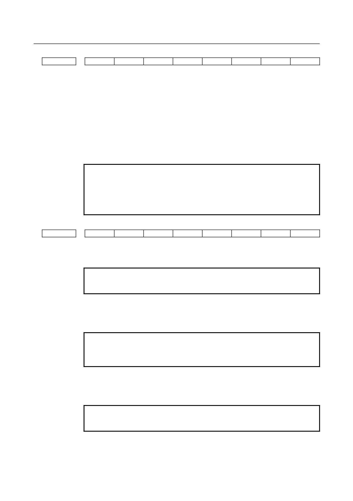
Set a minimum deceleration ratio (MDR) for an inner circular cutting feedrate change by
automatic corner override.
In the case of circular cutting offset inward, the actual feedrate is determined by a
specified feedrate (F) as follows:
Rc
Rc:Radius of tool center
F×
path
Rp
Rp:Programmed radius
Thus, the feedrate along the programmed path satisfies the specified value of F.
Programmed path
Rc
Tool center path
Rp
However, if Rc is too small when compared with Rp, Rc/Rp
0 results to stop the tool.
So, a minimum deceleration ratio (MDR) is set, and the feedrate of the tool is set to
F×(MDR) when Rc/Rp ≤ MDR.
NOTE
When this parameter is set to 0, the minimum deceleration ratio
(MDR) is 100%.
1711
Inner determination angle (θp) for inner corner override
[Input type] Parameter input
[Data type] Real path
[Unit of data] deg
[Min. unit of data] Depend on the increment system of the reference axis
[Valid data range] 2 to 178
Set an inner determination angle for inner corner override in automatic corner overriding.
1712
Override value for inner corner override
[Input type] Parameter input
[Data type] Byte path
[Unit of data] %
[Valid data range] 1 to 100
- 791 -

A.PARAMETERS
APPENDIX
B-64304EN/02
Set an inner corner override value in automatic corner overriding.
1713
Start distance (Le) for inner corner override
[Input type] Setting input
[Data type] Real path
[Unit of data] mm, inch (input unit)
[Min. unit of data] Depend on the increment system of the reference axis
[Valid data range] 9 digit of minimum unit of data (refer to standard parameter setting table (A))
(When the increment system is IS-B, -999999.999 to +999999.999)
Set a start distance for inner corner override in automatic corner overriding.
1714
End distance (Ls) for inner corner override
[Input type] Setting input
[Data type] Real path
[Unit of data] mm, inch (input unit)
[Min. unit of data] Depend on the increment system of the reference axis
[Valid data range] 9 digit of minimum unit of data (refer to standard parameter setting table (A))
(When the increment system is IS-B, -999999.999 to +999999.999)
Set an end distance for inner corner override in automatic corner overriding.
When θ ≤ θp, an inner corner is assumed. (Parameter No. 1711 is used to set θp.)
When a corner is determined to be an inner corner, an override is applied to the feedrate
in the range of Le in the previous block from the intersection of the corner and in the
range of Ls in the next block from the intersection of the corner.
Distances Le and Ls represent linear distances from the intersection of a corner to points
on the tool center path.
Le and Ls are set in parameter No. 1713 and No. 1714.
Minimum allowable feedrate for the deceleration function based on acceleration in circular
1732
interpolation
[Input type] Parameter input
[Data type] Real path
[Unit of data] mm/min, inch/min, degree/min (machine unit)
[Min. unit of data] Depend on the increment system of the reference axis
[Valid data range] Refer to the standard parameter setting table (C)
(When the increment system is IS-B, 0.0 to +999000.0)
With the deceleration function based on acceleration in circular interpolation, an optimum
feedrate is automatically calculated so that acceleration produced by changing the move
direction in circular interpolation does not exceed the maximum allowable acceleration
rate specified in parameter No. 1735.
If the radius of an arc is very small, a calculated feedrate may become too low.
In such a case, the feedrate is prevented from decreasing below the value specified in this
parameter.
Maximum allowable acceleration rate for the deceleration function based on acceleration in circular
1735
interpolation for each axis
[Input type] Parameter input
[Data type] Real axis
[Unit of data] mm/sec2, inch/sec2, degree/sec2 (machine unit)
- 792 -

B-64304EN/02
APPENDIX
A.PARAMETERS
[Min. unit of data] Depend on the increment system of the applied axis
[Valid data range] Refer to the standard parameter setting table (D)
(When the machine system is metric system, 0.0 to +100000.0. When the machine system
is inch system, machine, 0.0 to +10000.0.)
Set a maximum allowable acceleration rate for the deceleration function based on
acceleration in circular interpolation.
Feedrate is controlled so that acceleration produced by changing the move direction in
circular interpolation does not exceed the value specified in this parameter.
For an axis with 0 set in this parameter, the deceleration function based on acceleration is
disabled.
If a different value is set in this parameter for each axis, a feedrate is determined from the
smaller of the acceleration rates specified for the two circular axes.
1737
Maximum allowable acceleration rate for the deceleration function based on acceleration in AI contour
control for each axis
[Input type] Parameter input
[Data type] Real axis
[Unit of data] mm/sec2, inch/sec2, degree/sec2 (machine unit)
[Min. unit of data] Depend on the increment system of the applied axis
[Valid data range] Refer to the standard parameter setting table (D)
(When the machine system is metric system, 0.0 to +100000.0. When the machine system
is inch system, machine, 0.0 to +10000.0.)
Set a maximum allowable acceleration rate produced by changing the tool move
direction.
For an axis with 0 set in this parameter, the deceleration function based on acceleration is
disabled. If 0 is set for all axes, the deceleration function based on acceleration is not
performed.
In circular interpolation, however, the deceleration function based on feedrate control
using acceleration in circular interpolation (parameter No. 1735) is enabled.
1738
Minimum allowable feedrate for the deceleration function based on acceleration in AI contour control
[Input type] Parameter input
[Data type] Real path
[Unit of data] mm/min, inch/min, degree/min (machine unit)
[Min. unit of data] Depend on the increment system of the reference axis
[Valid data range] Refer to the standard parameter setting table (C)
(When the increment system is IS-B, 0.0 to +999000.0)
With the deceleration function based on acceleration in AI advanced preview control or
AI contour control, a feedrate most suitable for a desired figure is automatically
calculated.
Depending on the figure, however, the calculated feedrate may become too low.
In such a case, the feedrate is prevented from decreasing below the value specified in this
parameter.
Time constant for acceleration/deceleration after cutting feed interpolation in the
1769
acceleration/deceleration before interpolation mode
[Input type] Parameter input
[Data type] Word axis
[Unit of data] msec
[Valid data range] 0 to 4000
- 793 -
A.PARAMETERS
APPENDIX
B-64304EN/02
In the acceleration/deceleration before interpolation mode as in advanced preview control,
AI advanced preview control, or AI contour control, not the ordinary time constant
(parameter No. 1622) but the value of this parameter is used.
Be sure to specify the same time constant value for all axes except for a special
application. If different values are set, correct linear and circular figures cannot be
obtained.
1772
Acceleration change time of bell-shaped acceleration/deceleration before interpolation
[Input type] Parameter input
[Data type] 2-word path
[Unit of data] msec
[Valid data range] 0 to 200
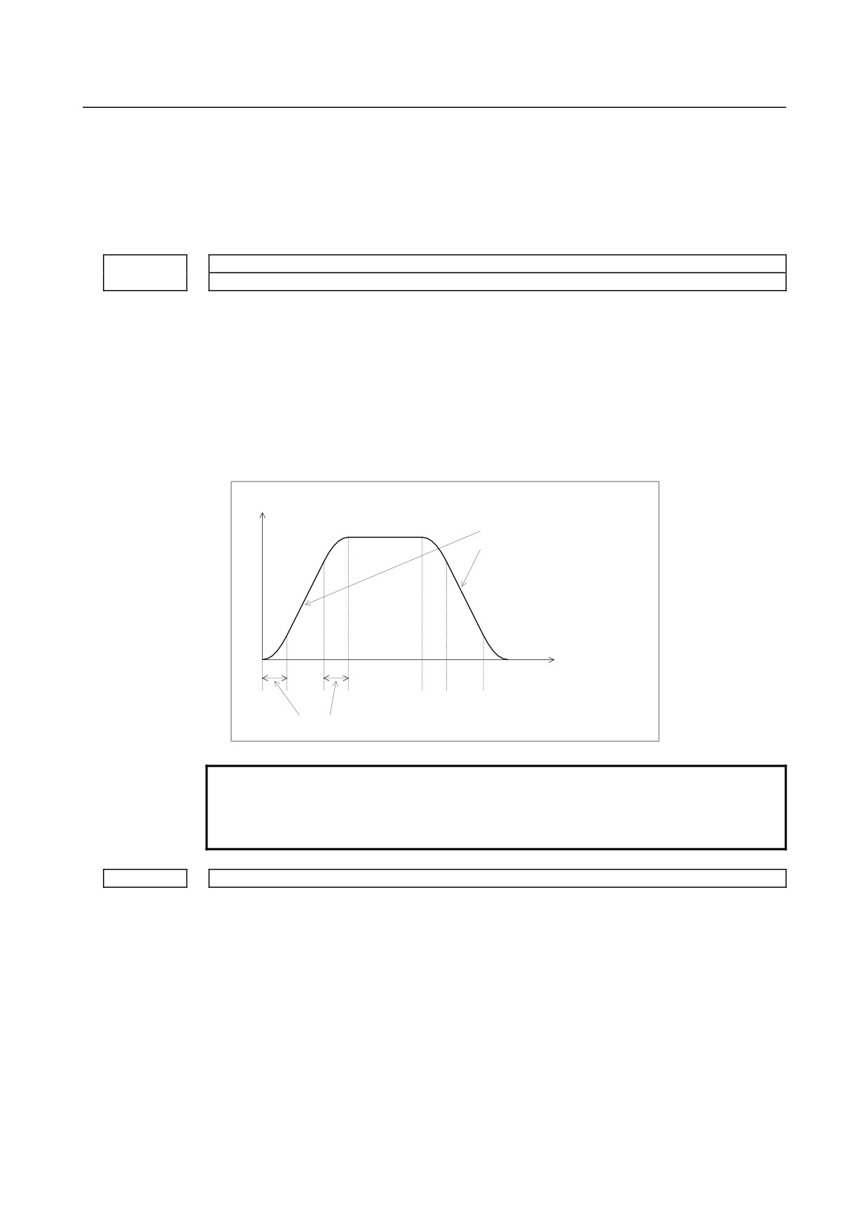
Set an acceleration change time of bell-shaped acceleration/ deceleration before
interpolation (time for changing from the state of constant feedrate (A) to the state of
constant acceleration/deceleration
(C) at the acceleration rate calculated from the
acceleration rate set in parameter No. 1660: time of (B) in the figure below).
Feedrate in tangent direction
Optimum inclination is automatically
calculated from the setting of parameter
No. 1660.
(A)
(B)
(C)
(B)
(A)
(B)
(C)
(B)
(A)
Time set by parameter No. 1772
NOTE
The option of bell-shaped acceleration/deceleration before
look-ahead interpolation is required. This parameter is valid only
in the AI contour control mode.
1783
Maximum allowable feedrate difference for feedrate determination based on corner feedrate difference
[Input type] Parameter input
[Data type] Real axis
[Unit of data] mm/min, inch/min, degree/min (machine unit)
[Min. unit of data] Depend on the increment system of the applied axis
[Valid data range] Refer to the standard parameter setting table (C)
(When the increment system is IS-B, 0.0 to +999000.0)
If a feedrate component change for each axis exceeding the value set in this parameter
occurs at the joint of blocks, the feedrate determination function based on corner feedrate
difference finds a feedrate not exceeding the set value and performs deceleration by using
acceleration/deceleration before interpolation. Thus, a shock to the machine and
machining error at a corner can be reduced.
- 794 -
B-64304EN/02
APPENDIX
A.PARAMETERS
#7
#6
#5
#4
#3
#2
#1
#0
1802
DC2x
DC4x
[Input type] Parameter input
[Data type] Bit axis
#1 DC4x When the reference position is established on the linear scale with reference marks:
0: An absolute position is established by detecting three reference marks.
1: An absolute position is established by detecting four reference marks.
#2 DC2x Reference position establishment operation for a linear scale with reference marks is
performed as follows:
0: The setting of bit 1 (DC4) of parameter No. 1802 is followed.
1: An absolute position is established by detecting two reference marks.
NOTE
1 When this parameter is set to 1, specify the direction of the scale
zero point by setting bit 4 (SCP) of parameter No. 1817.
2 When a rotary encoder with absolute address reference marks is
used, this parameter is invalid. Even when this parameter is set to
1, the setting of bit 1 (DC4) of parameter No. 1802 is followed.
#7
#6
#5
#4
#3
#2
#1
#0
1815
APCx
APZx
DCRx
OPTx
[Input type] Parameter input
[Data type] Bit axis
NOTE
When at least one of these parameters is set, the power must be
turned off before operation is continued.
#1 OPTx Position detector
0: A separate pulse coder is not used.
1: A separate pulse coder is used.
NOTE
Set this parameter to 1 when using a linear scale with reference
marks or a linear scale with an absolute address zero point
(full-closed system).
#3 DCRx As a scale with absolute address reference marks:
0: A rotary encoder with absolute address reference marks is not used.
1: A rotary encoder with absolute address reference marks is used.
NOTE
When using a rotary encoder with absolute address reference
marks, set also bit 2 (DCLx) of parameter No. 1815 to 1.
- 795 -
A.PARAMETERS
APPENDIX
B-64304EN/02
#4 APZx Machine position and position on absolute position detector when the absolute position
detector is used
0: Not corresponding
1: Corresponding
When an absolute position detector is used, after primary adjustment is performed or after
the absolute position detector is replaced, this parameter must be set to 0, power must be
turned off and on, then manual reference position return must be performed. This
completes the positional correspondence between the machine position and the position
on the absolute position detector, and sets this parameter to 1 automatically.
#5 APCx Position detector
0: Other than absolute position detector
1: Absolute position detector (absolute pulse coder)
#7
#6
#5
#4
#3
#2
#1
#0
1817
TANx
[Input type] Parameter input
[Data type] Bit axis
NOTE
When at least one of these parameters is set, the power must be
turned off before operation is continued.
#6 TANx Tandem control
0: Not used
1: Used
NOTE
Set this parameter to both master axis and slave axis.
#7
#6
#5
#4
#3
#2
#1
#0
1818
SDCx
RF2x
RFSx
[Input type] Parameter input
[Data type] Bit axis
#0 RFSx If G28 is specified for an axis for which a reference position is not established (ZRF = 0)
when a linear scale with an absolute address zero point or a linear scale with absolute
address reference marks is used:
0: A movement is made to the reference position after reference position establishment
operation.
1: No movement is made after reference position establishment operation, but the
operation is completed.
NOTE
This parameter disables movement based on the G28 command to
a reference position. So, use this parameter only in special cases.
- 796 -
B-64304EN/02
APPENDIX
A.PARAMETERS
#1 RF2x If G28 is specified for an axis for which a reference position is already established (ZRF
= 1) when a linear scale with an absolute address zero point or a linear scale with absolute
address reference marks is used:
0: A movement is made to the reference position.
1: No movement is made to the intermediate position and reference position, but the
operation is completed.
NOTE
This parameter disables movement based on the G28 command to
a reference position. So, use this parameter only in special cases.
#3 SDCx A linear scale with an absolute address zero point is:
0: Not used.
1: Used.
NOTE
1 After setting parameter SDCx, be sure to turn the power off and
back on again. Note that the power-off alarm (PW0000) is not
issued.
2 For the full-closed system, set bit 1 (OPTx) of parameter No. 1815
to 1.
#7
#6
#5
#4
#3
#2
#1
#0
1819
DATx
[Input type] Parameter input
[Data type] Bit axis
#2 DATx When a linear scale with an absolute address zero point or a linear scale with absolute
address reference marks is used, the automatic setting of parameter No. 1883 and No.
1884 at manual reference position return time is:
0: Not performed.
1: Performed.
The automatic setting procedure is as follows:
<1> Set an appropriate value in parameter No. 1815, No. 1821, and No. 1882.
<2> Position the machine at the reference position by manual operation.
<3> Set this parameter to 1.
<4> Perform a manual reference position return operation. Upon completion of manual
reference position return operation, parameter No. 1883 and No. 1884 are set, and
this parameter is automatically set to 0.
1820
Command multiplier for each axis (CMR)
NOTE
When this parameter is set, the power must be turned off before
operation is continued.
[Input type] Parameter input
[Data type] Byte axis
[Valid data range] See below :
Set a command multiplier indicating the ratio of the least command increment to the
detection unit for each axis.
- 797 -
A.PARAMETERS
APPENDIX
B-64304EN/02
Least command increment = detection unit × command multiplier
Relationship between the increment system and the least command increment
(1) T series
Least command
Least input increment
increment
Millimeter
0.001 mm
(diameter specification)
0.0005 mm
Millimeter
input
0.001 mm
(radius specification)
0.001 mm
machine
0.0001 inch
(diameter specification)
0.0005 mm
Inch input
0.0001 inch
(radius specification)
0.001 mm
IS-B
Millimeter
0.001 mm
(diameter specification)
0.00005 inch
Inch
input
0.001 mm
(radius specification)
0.0001 inch
machine
0.0001 inch
(diameter specification)
0.00005 inch
Inch input
0.0001 inch
(radius specification)
0.0001 inch
Rotation axis
0.001 deg
0.001 deg
Least command
Least input increment
increment
Millimeter
0.0001 mm
(diameter specification)
0.00005 mm
Millimeter
input
0.0001 mm
(radius specification)
0.0001 mm
machine
0.00001 inch
(diameter specification)
0.00005 mm
Inch input
0.00001 inch
(radius specification)
0.0001 mm
IS-C
Millimeter
0.0001 mm
(diameter specification)
0.000005 inch
Inch
input
0.0001 mm
(radius specification)
0.00001 inch
machine
0.00001 inch
(diameter specification)
0.000005 inch
Inch input
0.00001 inch
(radius specification)
0.00001 inch
Rotation axis
0.0001 deg
0.0001 deg
(2) M series
Least input increment and least command increment
Increment system
IS-A
IS-B
IS-C
Unit
Millimeter machine
0.01
0.001
0.0001
mm
Millimeter input
0.001
0.0001
0.00001
inch
Rotation axis
0.01
0.001
0.0001
deg
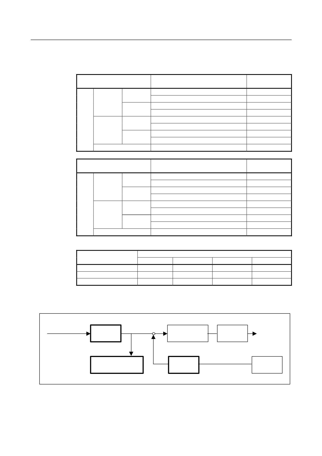
Setting command multiply (CMR), detection multiply (DMR), and the capacity of the
reference counter
Command pulse
+
DA
To
×CMR
Error counter
least
Converter
velocity
command
-
control
increment
Position
Reference counter
×DMR
Detection
Feedback
detector
unit
pulse
Set CMR and DMR so that the pulse weight of + input (command from the CNC) into the
error counter matches the pulse weight of -input (feedback from the position detector).
[Least command increment]/CMR=[Detection unit]=
[Feedback pulse unit]/DMR
[Least command increment]:
Minimum unit of commands issued from the CNC to the machine
- 798 -

B-64304EN/02
APPENDIX
A.PARAMETERS
[Detection unit]: Minimum unit for machine position detection
The unit of feedback pulses varies, depending on the type of detector.
[Feedback pulse unit]=[Amount of travel per rotation of the pulse coder]/[Number of
pulses per rotation of the pulse coder]
As the size of the reference counter, specify the grid interval for the reference position
return in the grid method.
[Size of the reference counter]=[Grid interval]/[Detection unit]
[Grid interval]=[Amount of travel per rotation of the pulse coder]
The setting of a command multiplier is as follows:
(1) When command multiplier is 1 to 1/27
Set value = 1 / command multiplier + 100
Valid data range : 101 to 127
(2) When command multiply is 0.5 to 48
Set value = 2 × command multiplier
Valid data range : 1 to 96
NOTE
1 If a feedrate exceeding the feedrate found by the expression below
is used, an incorrect travel amount may result or a servo alarm may
be issued. Be sure to use a feedrate not exceeding the feedrate
found by the following expression:
Fmax[mm/min] = 196602 × 104 × least command increment / CMR
2 For the FS0i-C, one of the following changes is required besides
setting bit 3 (DIAx) of parameter No. 1006 so that the axis based
on diameter specification achieves the specified amount of
movement.
• Halve the command multiplication (the detection unit is not
changed).
• Halve the detection unit and double the flexible feed gear
(DMR).
For the FS0i-D, only if bit 3 (DIAx) of parameter No. 1006 is set,
the CNC halves the specified pulse. Accordingly, the above
changes are not required (when the detection unit is not changed).
To halve the detection unit, double both CMR and DMR.
1821
Reference counter size for each axis
NOTE
When this parameter is set, the power must be turned off before
operation is continued.
[Input type] Parameter input
[Data type] 2-word axis
[Unit of data] Detection unit
[Valid data range] 0 to 999999999
Set a reference counter size.
As a reference counter size, specify a grid interval for reference position return based on
the grid method.
When a value less than 0 is set, the specification of 10000 is assumed.
- 799 -

A.PARAMETERS
APPENDIX
B-64304EN/02
When a linear scale with absolute address reference marks is used, set the interval of
mark 1.
1828
Positioning deviation limit for each axis in movement
[Input type] Parameter input
[Data type] 2-word axis
[Unit of data] Detection unit
[Valid data range] 0 to 99999999
Set the positioning deviation limit in movement for each axis.
If the positioning deviation exceeds the positioning deviation limit during movement, a
servo alarm
(SV0411) is generated, and operation is stopped immediately
(as in
emergency stop).
Generally, set the positioning deviation for rapid traverse plus some margin in this
parameter.
1829
Positioning deviation limit for each axis in the stopped state
[Input type] Parameter input
[Data type] 2-word axis
[Unit of data] Detection unit
[Valid data range] 0 to 99999999
Set the positioning deviation limit in the stopped state for each axis.
If, in the stopped state, the positioning deviation exceeds the positioning deviation limit
set for stopped state, a servo alarm (SV0410) is generated, and operation is stopped
immediately (as in emergency stop).
1851
Backlash compensating value for each axis
[Input type] Parameter input
[Data type] Word axis
[Unit of data] Detection unit
[Valid data range] -9999 to 9999
Set the backlash compensating value for each axis.
When the machine moves in a direction opposite to the reference position return direction
after the power is turned on, the first backlash compensation is performed.
1882
Interval of mark 2 of a linear scale with absolute address reference marks
NOTE
When this parameter is set, the power must be turned off before
operation is continued.
[Input type] Parameter input
[Data type] 2-word axis
[Unit of data] Detection unit
[Valid data range] 0 to 999999999
Set the interval of mark 2 of a linear scale with absolute address reference marks.
- 800 -
B-64304EN/02
APPENDIX
A.PARAMETERS
Distance 1 from the scale zero point to reference position (linear scale with absolute address reference
1883
marks) or distance 1 from the base point to reference position (linear scale with an absolute address
zero point)
NOTE
When this parameter is set, the power must be turned off before
operation is continued.
[Input type] Parameter input
[Data type] 2-word axis
[Unit of data] Detection unit
[Valid data range] -999999999 to 999999999
Distance 2 from the scale zero point to reference position (linear scale with absolute address reference
1884
marks) or distance 2 from the base point to reference position (linear scale with an absolute address
zero point)
NOTE
When this parameter is set, the power must be turned off before
operation is continued.
[Input type] Parameter input
[Data type] 2-word axis
[Unit of data] Detection unit
[Valid data range] -999 to 999
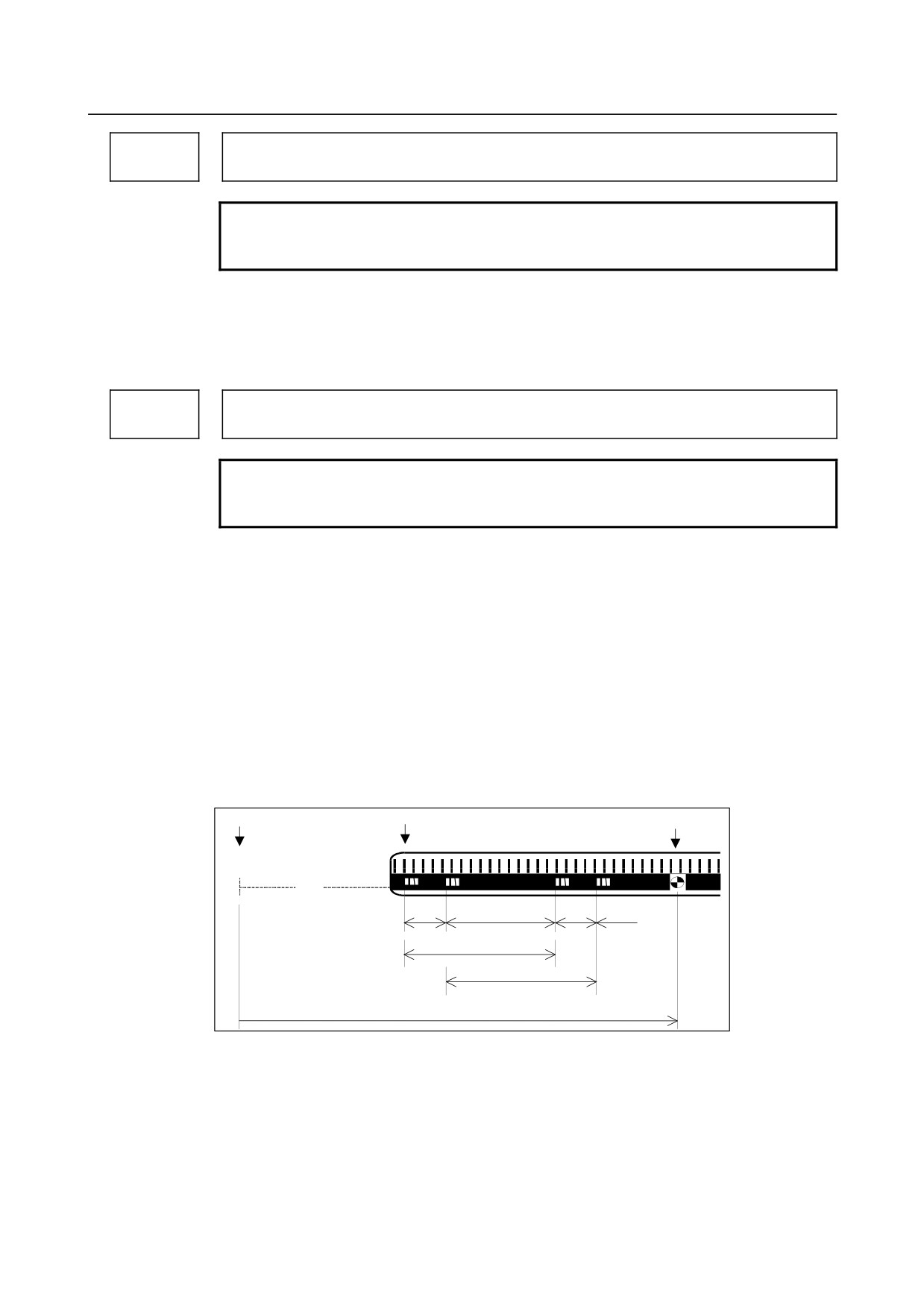
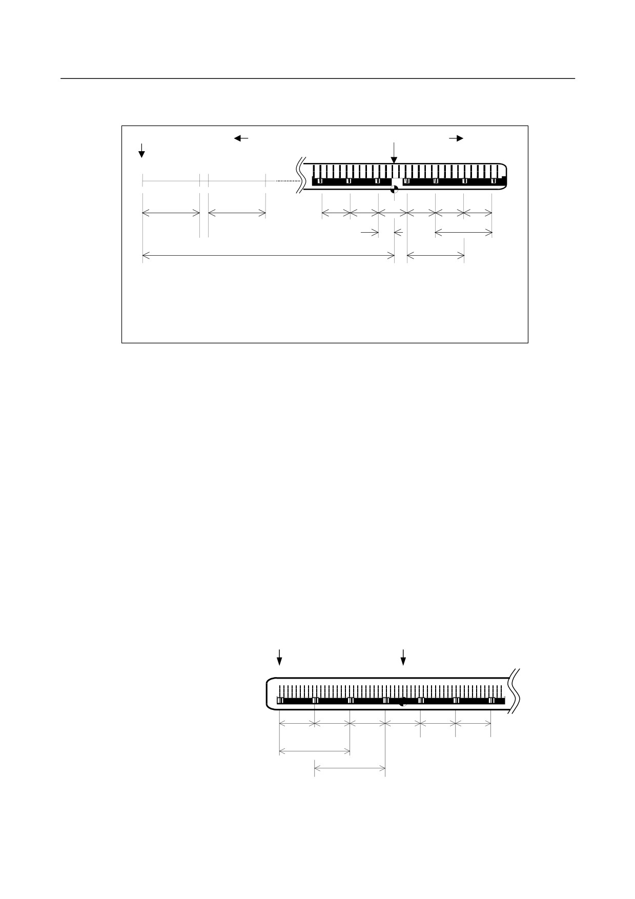
When a linear scale with absolute address reference marks is used, set the distance from
the scale zero point to reference position in parameter Nos. 1883 and 1884).
Distance from the zero point to the reference position of a linear scale
= No. 1884 × 1,000,000,000 + No. 1883
The scale zero point represents a point where mark 1 and mark 2 match. Usually, this
point is a virtual point that does not physically exist on the scale. (See the figure below.)
If the reference position is placed in the + direction when viewed from the scale zero
point, set a positive value. If the reference position is placed in the - direction when
viewed from the scale zero point, set a negative value.
Zero point of encoder
Encoder end
Reference position
Mark 1 Mark 2
Mark 1 Mark 2
Mark 1 = mark 2
・・・・
8.0
42.0
8.2
41.8
Parameter No.1821
Parameter No.1882
Parameter No.1884) × 1,000,000,000 + Parameter No.1883
- 801 -
A.PARAMETERS
APPENDIX
B-64304EN/02
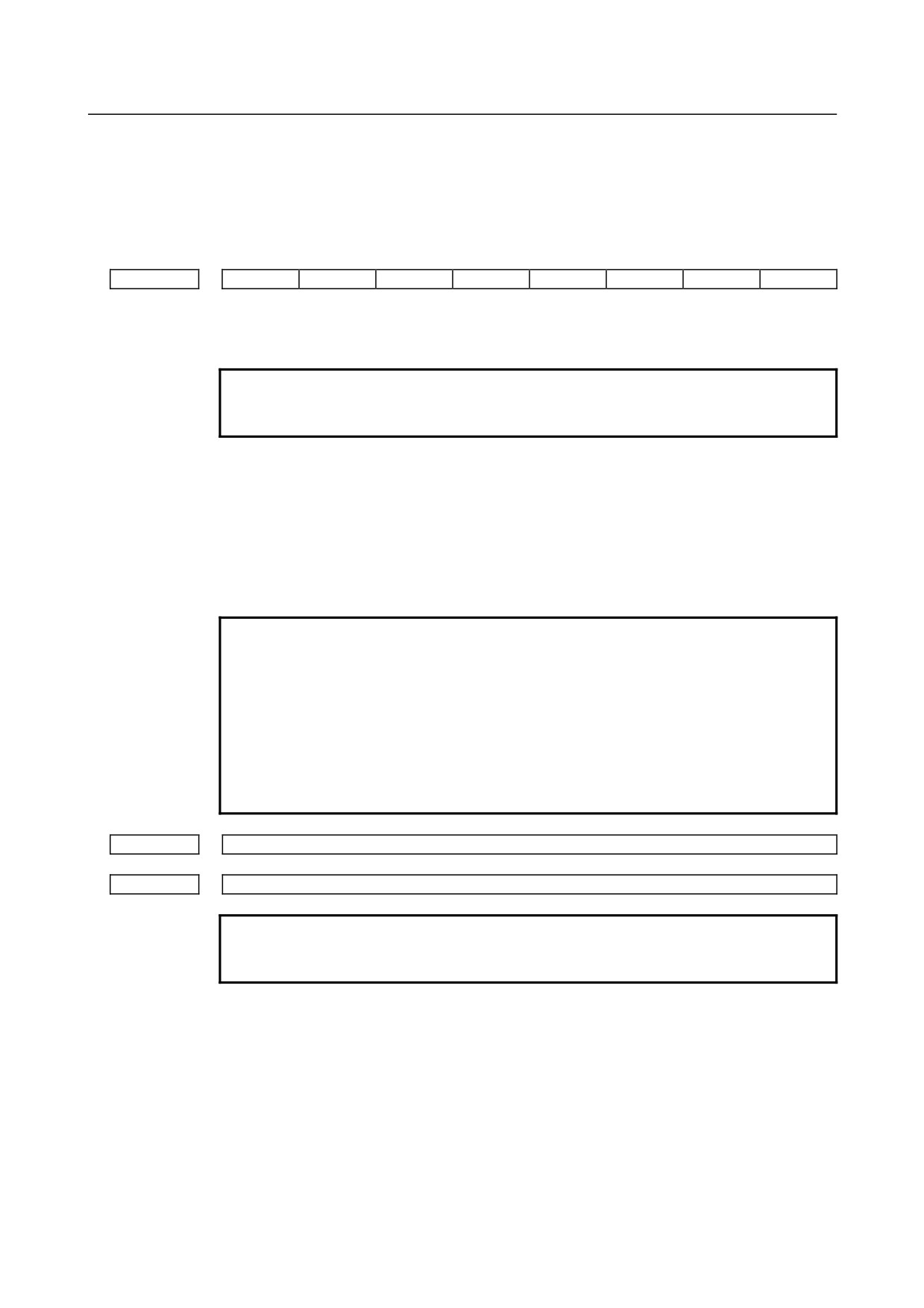
[Example of parameter settings]
When an encoder as shown below is used with an IS-B, millimeter machine:
Scale zero point
+ direction
Reference position
- direction
A
B
Mark 1 Mark 2
Mark 1
Mark 2 Mark 1 Mark 2 Mark 1
Mark 1 = mark 2
Mark 1 Mark 2
Mark 1
9.940
10.060
9.960
10.040
9.980
10.020
20.00
19.980
0
5.000
20.000mm
-[9960/(20020-20000)*20000+5000] = -9965000
20.020mm
Parameters No.1821 (interval of mark 1)
=
20000
No.1882 (interval of mark 2)
=
20020
No.1883 (reference position)
=
position of point A + 5.000
=
distance between A and B/(mark 2 - mark 1) × mark 1+ 5000
=
9960/ (20020 - 20000) × 20000+5000
=
9965000
=
-9965000 (the reference position is on the negative side)
[Setting parameter No. 1883]
When it is difficult to measure the distance from the scale zero point to the reference
position (parameter No. 1883), the method described below can be used to find the
distance.
<1> Set parameter No. 1815 to enable this function.
Set an appropriate value in parameter No. 1821 and No. 1882.
Set 0 in parameter No. 1240.
Set 0 in parameter No. 1883 and No. 1884.
<2> At an appropriate position, establish a reference position.
(As a result, the machine coordinate represents the distance from the scale zero point
to the current position.)
<3> By jog feed or handle feed, place the machine at the accurate reference position.
<4> In parameter No. 1883, set the machine coordinate of that time converted to the
detection unit (machine coordinate × CMR).
<5> If necessary, set parameter No. 1240.
When a linear scale with an absolute address zero point is used, set the distance from the
base point to the reference position in parameter Nos. 1883 and 1884. The base point is a
point at a scale end as shown below.
Base point
Reference position
Mark 1 Mark 2
Mark 1
Mark 2
Mark 1
Mark 2 Mark 1
10.020
9.980
10.040
9.960
10.060
9.940
20.000
20.020
If the reference position is located in the positive direction when viewed from the base
point, set a positive value; if the reference position is located in the negative direction, set
a negative value. Set the value by following the steps explained below.
- 802 -

B-64304EN/02
APPENDIX
A.PARAMETERS
<1> Set bit 1 (OPT) of parameter No. 1815 , bit 2 (DCL) of parameter No. 1815, and bit
3 (SDC) of parameter No. 1818 to enable this function.
Set 0 in parameter No. 1240.
Set 0 in parameter No. 1883 and No. 1884.
<2> At an appropriate position, establish a reference position.
(Consequently, the machine coordinate value indicates the distance from the base
point to current position.)
<3> By jog feed or handle feed, place the machine at the accurate reference position.
<4> In parameters Nos. 1883 and 1884, set the machine coordinate of that time converted
to the detection unit (machine coordinate × CMR).
If necessary, set parameter No. 1240.
NOTE
1 Set parameter Nos. 1883 and 1884 so that the distance from the
scale zero point (for a linear scale with absolute address reference
marks) or the base point (for a linear scale with an absolute
address zero point) to the reference position is within the range
from -999,999,999,999 to +999,999,999,999. If a value beyond this
range is set, an alarm (PS 5325) is issued.
2 The scale area on the scale cannot be extended across the scale
zero point or base point. Make parameter settings not to cause the
scale area to extend beyond the scale zero point or base point.
#7
#6
#5
#4
#3
#2
#1
#0
1902
ASE
FMD
[Input type] Parameter input
[Data type] Bit
NOTE
When at least one of these parameters is set, the power must be
turned off before operation is continued.
#0 FMD The FSSB setting mode is:
0: Automatic setting mode.
(When bit 0 (DFS) of parameter No. 14476 is 0:
If the relationship between the axis and the amplifier and the like are defined on the
FSSB setting screen, parameters No. 1023, No. 1905, Nos. 1936 and 1937, Nos.
14340 to 14357, and Nos. 14376 to 14391 are automatically set.)
(When bit 0 (DFS) of parameter No. 14476 is 1:
If the relationship between the axis and the amplifier and the like are defined on the
FSSB setting screen, parameters No. 1023, No. 1905, Nos. 1910 to 1919, and Nos.
1936 and 1937 are automatically set.)
1: Manual setting 2 mode.
(When bit 0 (DFS) of parameter No. 14476 is 0:
Manually set parameters No.1023, No.1905, Nos.1936 and 1937, Nos.14340 to
14357, and Nos.14376 to 14391.)
(When bit 0 (DFS) of parameter No. 14476 is 1:
Manually set parameters No.1023, No.1905, Nos.1910 to 1919, and Nos. 1936 and
1937.)
- 803 -
A.PARAMETERS
APPENDIX
B-64304EN/02
#1 ASE When automatic setting mode is selected for FSSB setting (when the FMD parameter (bit
0 of parameter No.1902) is set to 0), automatic setting is:
0: Not completed.
1: Completed.
This bit is automatically set to 1 upon the completion of automatic setting.
#7
#6
#5
#4
#3
#2
#1
#0
1905
PM2x
PM1x
[Input type] Parameter input
[Data type] Bit axis
NOTE
When at least one of these parameters is set, the power must be
turned off before operation is continued.
#6 PM1x The first separate detector interface unit is:
0: Not used.
1: Used.
#7 PM2x The second separate detector interface unit is:
0: Not used.
1: Used.
NOTE
When automatic setting mode is selected for FSSB setting (when
the parameter FMD (No.1902#0) is set to 0), this parameter is
automatically set when input is performed with the FSSB setting
screen. When manual setting 2 mode is selected for FSSB setting
(when the parameter FMD (No.1902#0) is set to 1), this parameter
must be set directly. When a separate detector interface unit is
used, a connector number must be set in the corresponding
parameter (No.1936 or No.1937).
1936
Connector number of the first separate detector interface unit
1937
Connector number of the second separate detector interface unit
NOTE
When these parameters are set, the power must be turned off before
operation is continued.
[Input type] Parameter input
[Data type] Byte axis
[Valid data range] 0 to 7
This parameter sets the connector number corresponding to the connector connected
when using the separator detector interface unit set by bits 6 and 7 of parameter No. 1905
minus 1. That is, set 0 to 7 for connector numbers 1 to 8, respectively. Set 0 for the
axis for which the separator detector interface unit is not used.
Use successive numbers for one separator detector interface unit. Do not omit a
intermediate number.
- 804 -
B-64304EN/02
APPENDIX
A.PARAMETERS
Example)
Connector number
Connector number
Controlled
for the first separate
for the second
PM2x, PM1x
No.1936
No.1937
axis
detector interface
separate detector
(No.1905#7, #6)
unit
interface unit
X
1
Not used
0
0
0, 1
Y
Not used
2
0
1
1, 0
Z
Not used
1
0
0
1, 0
A
Not used
Not used
0
0
0, 0
NOTE
When automatic setting mode is selected for FSSB setting (when the
parameter FMD (No.1902#0) is set to 0), these parameters are
automatically set when input is performed with the FSSB setting
screen. When manual setting 2 mode is selected for FSSB setting
(when the parameter FMD (No.1902#0) is set to 1), these
parameters must be set directly.
Parameters No.2000 to 2999 are for digital servo. Refer to FANUC AC SERVO MOTOR αi series
PARAMETER MANUAL (B-65270EN)
#7
#6
#5
#4
#3
#2
#1
#0
2011
XIAx
[Input type] Parameter input
[Data type] Bit axis
#7 XIAx Temporary absolute coordinate setting is:
0: Not used.
1: Used.
NOTE
1 When temporary absolute coordinate setting is used, bit 1 (OPTx)
of parameter No. 1815, bit 5 (APCx) of parameter No. 1815,
parameter No. 1874, and parameter No. 1875 must be set.
2 The setting of this parameter becomes effective after the power is
turned off then back on.
2031
Torque command difference threshold of torque difference alarm
[Input type] Parameter input
[Data type] Word axis
[Valid data range] 0 to 14564
If the absolute value of the torque command difference between two axes exceeds the
value set in this parameter, an alarm is issued.
Set the same value for two axes that are placed under axis synchronous control.
The servo axis numbers of the synchronized master axis and slave axis must be assigned
so that an odd number is assigned to the master axis and the next axis number is assigned
to the slave axis. Examples are (1,2) and (3,4).
- 805 -
A.PARAMETERS
APPENDIX
B-64304EN/02
#7
#6
#5
#4
#3
#2
#1
#0
MVG
3003
[Input type] Parameter input
[Data type] Bit path
#7 MVGDuring drawing with the dynamic graphic display function, the axis movement signal is:
0: Output.
1: Not output.
#7
#6
#5
#4
#3
#2
#1
#0
3008
XSG
[Input type] Parameter input
[Data type] Bit path
NOTE
When this parameter is set, the power must be turned off before
operation is continued.
#2 XSG A signal assigned to an X address is:
0: Fixed at the address.
1: Able to be reassigned to an arbitrary X address.
NOTE
When this parameter is set to 1, set parameter No. 3013, No. 3014,
No. 3012, and No. 3019. If parameter No. 3013 and No. 3014 are
not set, the deceleration signal for reference position return is
assigned to bit 0 of X0000. If parameter No. 3012 and No. 3019 are
not set, the skip signal, the PMC axis control skip signal, the
measurement position arrival signal, the interlock signal for each
axis direction, and the tool compensation value write signal are
assigned to X0000.
3012
Skip signal assignment address
NOTE
When this parameter is set, the power must be turned off before
operation is continued.
[Input type] Parameter input
[Data type] Word path
[Valid data range] 0 to 327
Set an X address to which the skip signal (SKIPn) is to be assigned.
- 806 -
B-64304EN/02
APPENDIX
A.PARAMETERS
NOTE
This parameter is valid when bit 2 (XSG) of parameter No. 3008 is
set to 1.
The X addresses that can be actually used are shown below, but
they depend on the configuration of I/O Link point count expansion
options.
X0 to X127, X200 to X327
3013
X address to which the deceleration signal for reference position return is assigned
NOTE
When this parameter is set, the power must be turned off before
operation is continued.
[Input type] Parameter input
[Data type] Word axis
[Valid data range] 0 to 327
Set an address to which the deceleration signal (*DECn) for reference position return for
each axis is to be assigned.
NOTE
This parameter is valid when bit 2 (XSG) of parameter No. 3008 is
set to 1.
The X addresses that can be actually used are shown below, but
they depend on the configuration of I/O Link point count expansion
options.
X0 to X127, X200 to X327
Address to which the PMC axis control skip signal and the measurement position arrival signal are
3019
assigned
NOTE
When this parameter is set, the power must be turned off before
operation is continued.
[Input type] Parameter input
[Data type] Word path
[Valid data range] 0 to 327
Sets addresses to which X address PMC axis control skip signal ESKIP, measurement
position arrival signals
(XAE1, XAE2, and XAE3 (M series); XAE1 and XAE2 (T
series)), and tool compensation write signals (±MIT1 and ±MIT2 (T series)) are allocated.
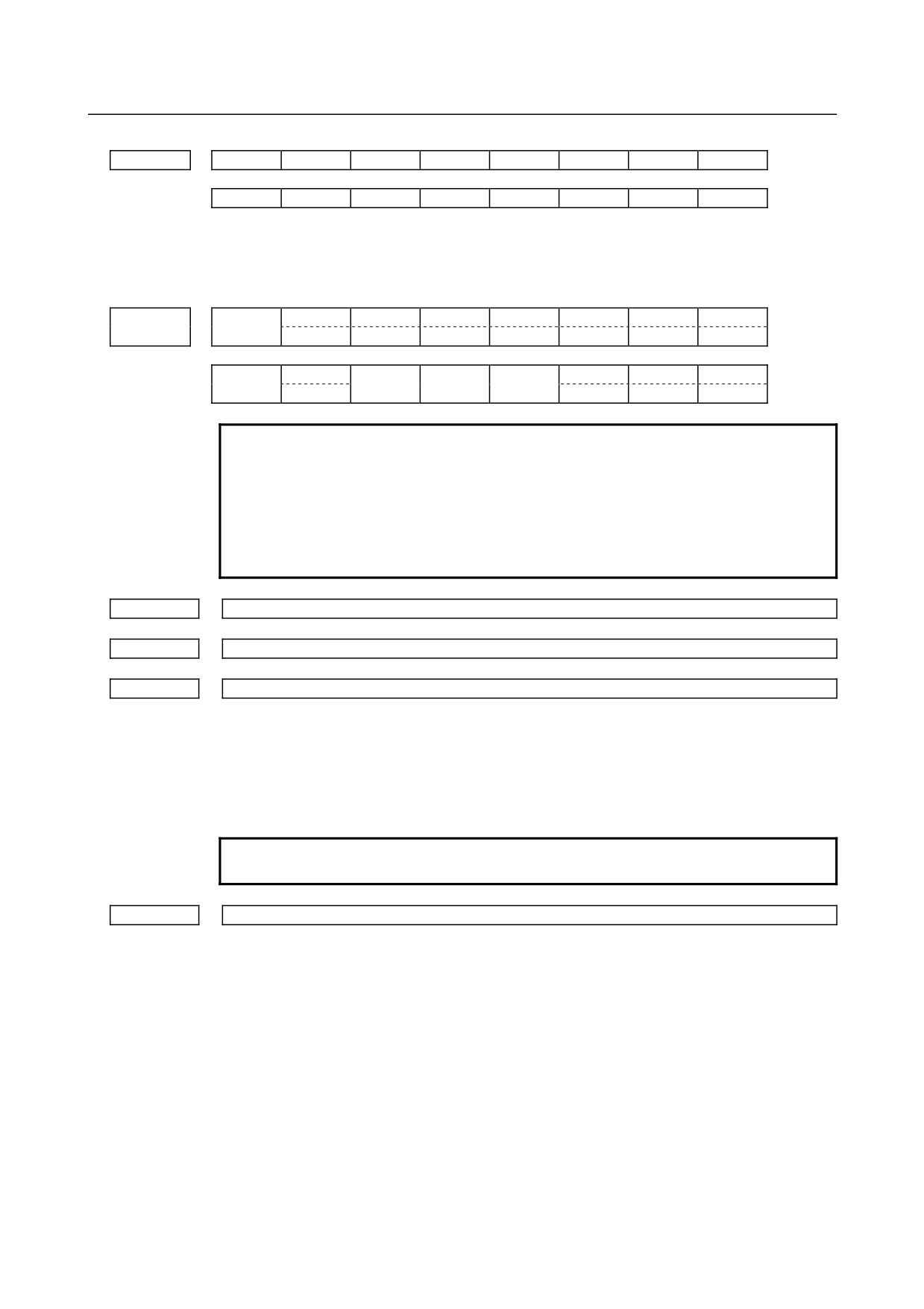
Example 1. When No.3012 is set to 5 and No.3019 is set to 6
When XSG (bit 2 of parameter No. 3008) is 1, the PMC axis control skip signal, and
measurement position arrival signal are allocated to X0006 and the skip signal is
allocated to X0005.
#7
#6
#5
#4
#3
#2
#1
#0
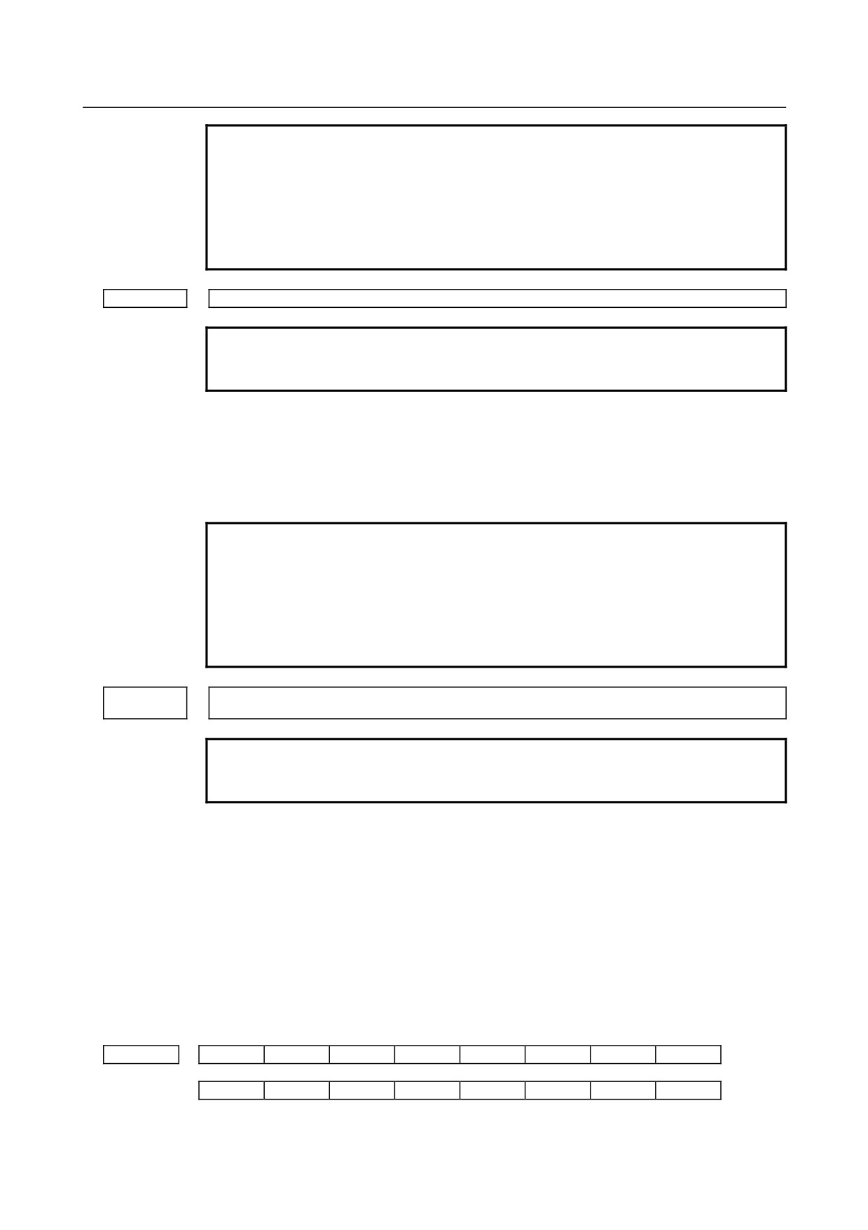
X005
SKIP
SKIP6
SKIP5
SKIP4
SKIP3
SKIP2
SKIP8
SKIP7
(T series)
#7
#6
#5
#4
#3
#2
#1
#0
SKIP
SKIP6
SKIP5
SKIP4
SKIP3
SKIP2
SKIP8
SKIP7
(M series)
- 807 -
A.PARAMETERS
APPENDIX
B-64304EN/02
#7
#6
#5
#4
#3
#2
#1
#0
X006
ESKIP
-MIT2
+MIT2
-MIT1
+MIT1
XAE2
XAE1
(T series)
#7
#6
#5
#4
#3
#2
#1
#0
ESKIP
XAE3
XAE2
XAE1
(M series)
Example 2. When No.3012 is set to 5 and No.3019 is set to 5
When XSG (bit 2 of parameter No. 3008) is 1, the PMC axis control skip signal,
measurement position arrival signal, and skip signal are allocated to X0005.
#7
#6
#5
#4
#3
#2
#1
#0
ESKIP
-MIT2
+MIT2
-MIT1
+MIT1
XAE2
XAE1
X005
SKIP
(T series)
SKIP6
SKIP5
SKIP4
SKIP3
SKIP2
SKIP8
SKIP7
#7
#6
#5
#4
#3
#2
#1
#0
ESKIP
XAE3
XAE2
XAE1
SKIP
SKIP5
SKIP4
SKIP3
(M series)
SKIP6
SKIP2
SKIP8
SKIP7
NOTE
This parameter is valid when bit 2 (XSG) of parameter No. 3008 is
set to 1.
The X addresses that can be actually used are shown below, but
they depend on the configuration of I/O Link point count expansion
options.
X0 to X127, X200 to X327
3030
Allowable number of digits for the M code
3031
Allowable number of digits for the S code
3032
Allowable number of digits for the T code
[Input type] Parameter input
[Data type] Byte path
[Valid data range] 1 to 8
Set the allowable numbers of digits for the M, S, and T codes.
When 0 is set, the allowable number of digits is assumed to be 8.
NOTE
Up to 5 digits can be specified in the S code.
3033
Allowable number of digits for the B code (second auxiliary function)
[Input type] Parameter input
[Data type] Byte path
[Valid data range] 1 to 8
Set the allowable number of digits for the second auxiliary function.
When 0 is set, the allowable number of digits is assumed to be 8.
To enable a decimal point to be specified, bit 0 (AUP) of parameter No. 3450 must be set
to 1. In this case, the allowable number of digits set in this parameter includes the number
of decimal places.
If a value exceeding the allowable number of digits is specified, the alarm (PS0003) is
issued.
- 808 -

B-64304EN/02
APPENDIX
A.PARAMETERS
#7
#6
#5
#4
#3
#2
#1
#0
DAC
DRC
PPD
MCN
3104
DAC
DAL
DRC
DRL
PPD
MCN
[Input type] Parameter input
[Data type] Bit path
#0 MCN Machine position
0: Regardless of whether input is made in mm or inches, the machine position is
displayed in mm for millimeter machines, or in inches for inch machines.
1: When input is made in mm, the machine position is displayed in mm, and when
input is made in inches, the machine position is displayed in inches accordingly.
#3 PPD Relative position display when a coordinate system is set
0: Not preset
1: Preset
NOTE
If any of the following is executed when PPD is set to 1, the relative
position display is preset to the same value as the absolute position
display:
(1) Manual reference position return
(2) Coordinate system setting based on G92 (G50 for G code
system A on the lathe system)
(3) Workpiece coordinate system presetting based on G92.1
(G50.3 for G code system A on the lath system)
(4) When a T code for the T series is specified.
#4 DRL Relative position
0: The actual position displayed takes into account tool length offset.
1: The programmed position displayed does not take into account tool length offset.
NOTE
In the T series, whether to exclude a tool offset when displaying the
relative position is determined by the setting of bit 0 (DRP) of
parameter No. 3129.
#5 DRC When relative positions are displayed:
0: Values not excluding the amount of travel based on cutter compensation and tool
nose radius compensation are displayed.
1: Values excluding the amount of travel based on cutter compensation and tool nose
radius compensation (programmed positions) are displayed.
#6 DAL Absolute position
0: The actual position displayed takes into account tool length offset.
1: The programmed position displayed does not take into account tool length offset.
NOTE
In T series, whether to exclude a tool offset when displaying the
absolute position is determined by the setting of bit 1 (DAP) of
parameter No. 3129.
- 809 -

A.PARAMETERS
APPENDIX
B-64304EN/02
#7 DAC When an absolute position are displayed:
0: Values not excluding the amount of travel based on cutter compensation and tool
nose radius compensation are displayed.
1: Values excluding the amount of travel based on cutter compensation and tool nose
radius compensation (programmed positions) are displayed.
#7
#6
#5
#4
#3
#2
#1
#0
3106
OPH
[Input type] Setting input
[Data type] Bit
#4 OPH The operation history screen is:
0: Not displayed.
1: Displayed.
#7
#6
#5
#4
#3
#2
#1
#0
3107
MDL
GSC
[Input type] Parameter input
[Data type] Bit path
#3 GSC The feedrate to be displayed is:
0: Feedrate per minute.
1: Determined by bit 5 (FSS) of parameter No. 3191.
#7 MDL The modal state on the program(MDI) screen of the 8.4 inch screen is:
0: Not displayed.
1: Displayed.
#7
#6
#5
#4
#3
#2
#1
#0
3111
OPS
OPM
SVP
SPS
SVS
[Input type] Setting input
[Data type] Bit path
#0 SVS The soft key for displaying the servo setting screen is:
0: Not displayed.
1: Displayed.
#1 SPS The soft key for displaying the spindle setting screen is:
0: Not displayed.
1: Displayed.
#2 SVP Spindle synchronization errors displayed on the spindle tuning screen
0: Instantaneous values are displayed.
1: Peak-hold values are displayed.
Spindle synchronization errors are displayed on the side of the spindle that functions as a
slave axis in spindle synchronization control.
#5 OPM Operating monitor
0: Not displayed
1: Displayed
- 810 -
B-64304EN/02
APPENDIX
A.PARAMETERS
#6 OPS The speedometer on the operating monitor screen indicates:
0: Spindle motor speed
1: Spindle speed
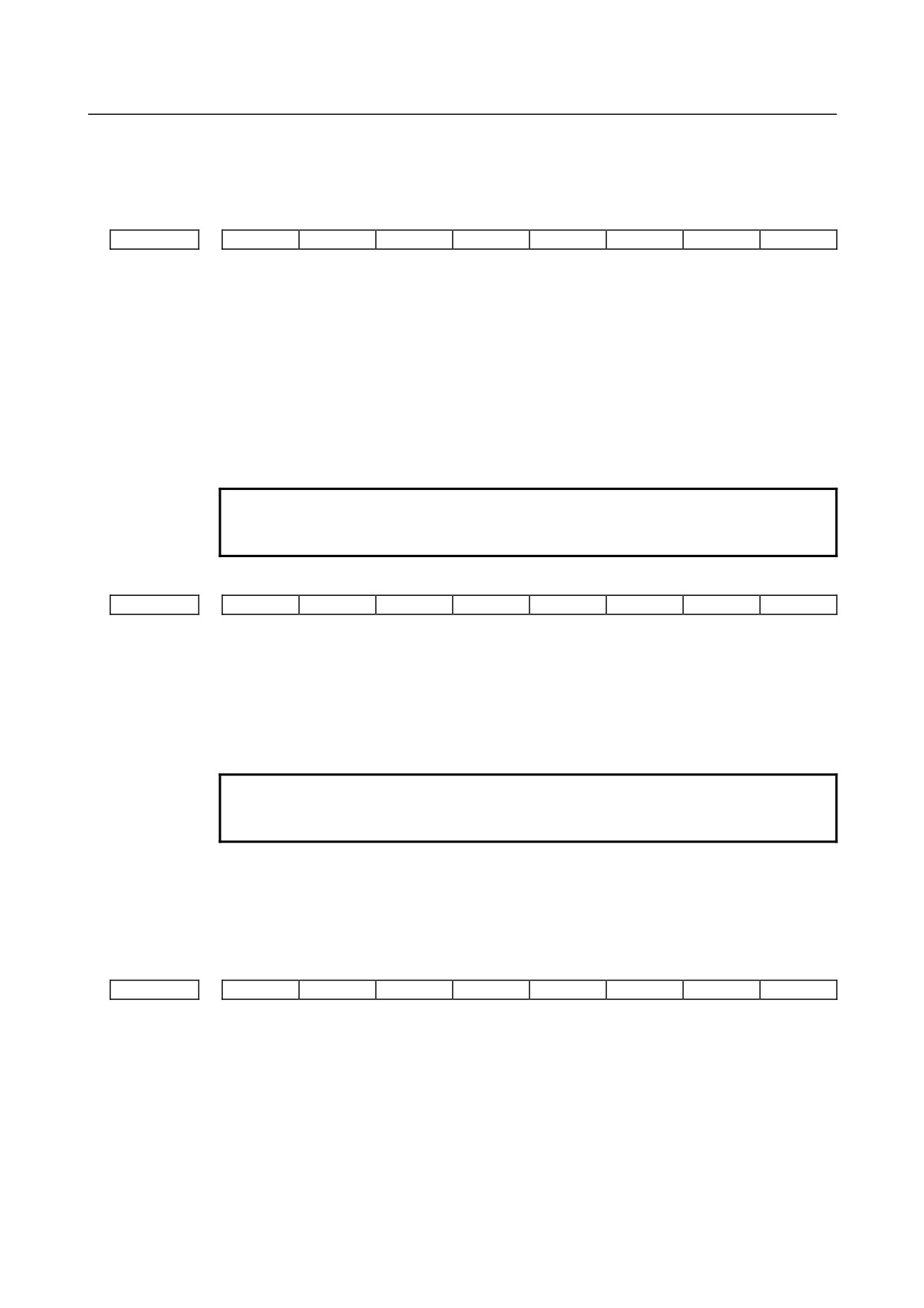
#7
#6
#5
#4
#3
#2
#1
#0
3112
EAH
OMH
[Input type] Parameter input
[Data type] Bit
#2 OMH The external operator message history screen is:
0: Not displayed.
1: Displayed.
#3 EAH Messages of the external alarm/macro alarm in alarm or operation history:
0: Not recorded
1: Recorded
NOTE
This parameter is valid when bit 7 (HAL) of parameter No. 3196 is
set to 0.
#7
#6
#5
#4
#3
#2
#1
#0
3115
NDAx
NDPx
[Input type] Parameter input
[Data type] Bit axis
#0 NDPx The current position is:
0: Displayed.
1: Not displayed.
NOTE
When using the electric gear box (EGB) function (M series), set 1
for the EGB dummy axis to disable current position display.
#1 NDAx The current position and the amount of the movement to be made in absolute and relative
coordinates are:
0: Displayed.
1: Not displayed.
#7
#6
#5
#4
#3
#2
#1
#0
3117
SMS
[Input type] Parameter input
[Data type] Bit path
#0 SMS On the program check screen of the 8.4-inch display unit, the function for displaying the
spindle load meter and spindle speed meter in the remaining movement amount display
position and modal information display position is:
0: Disabled.
1: Enabled.
- 811 -
A.PARAMETERS
APPENDIX
B-64304EN/02
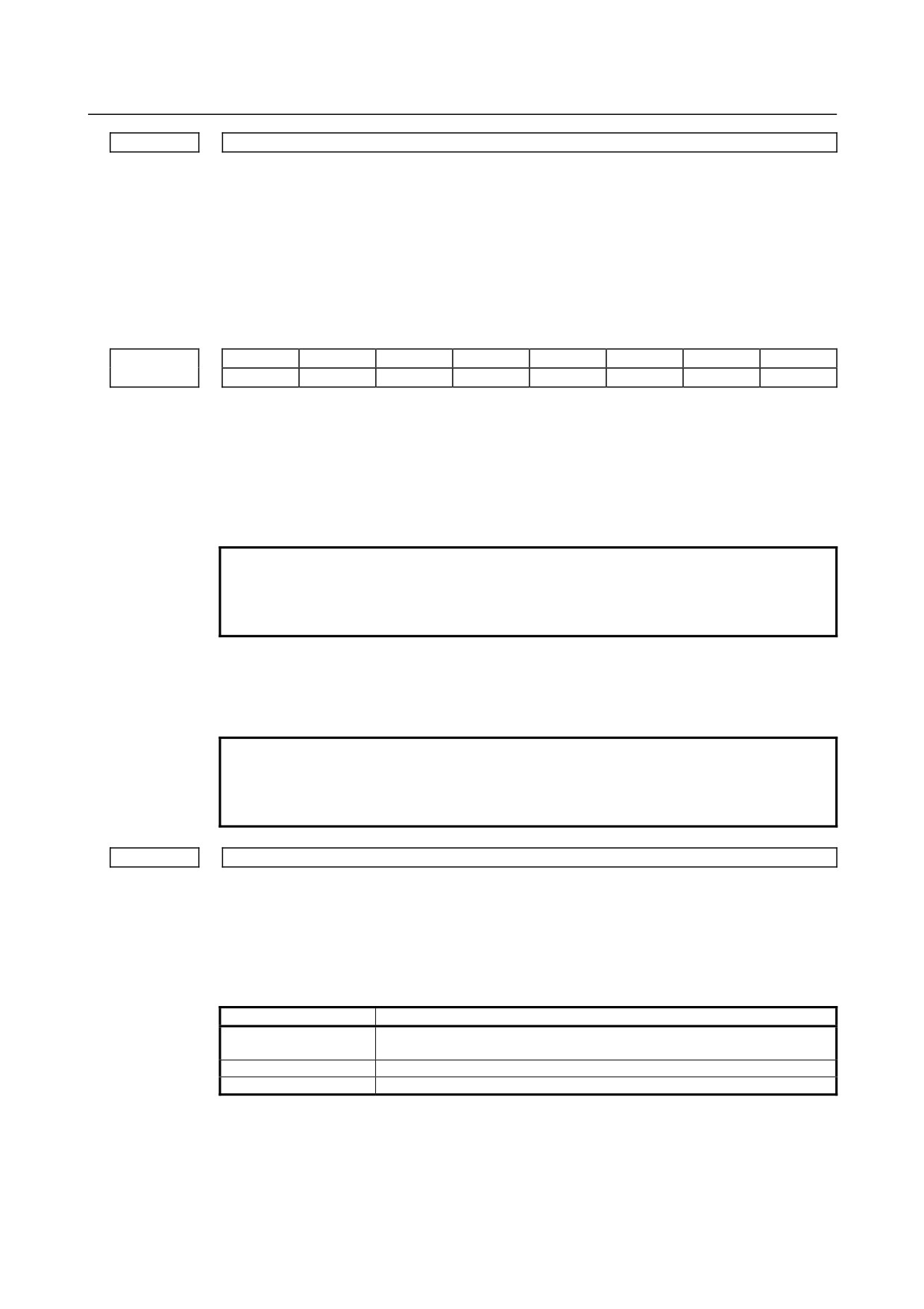
3122
Time interval used to record time data in operation history
[Input type] Parameter input
[Data type] Word path
[Unit of data] min
[Valid data range] 0 to 1440
When history data is recorded within a set time period, the time for each set time period is
recorded in the history data.
When 0 is set, the specification of a time period of 10 minutes is assumed.
#7
#6
#5
#4
#3
#2
#1
#0
DAP
DRP
3129
[Input type] Parameter input
[Data type] Bit path
#0 DRP For relative position display:
0: The actual position considering a tool offset (tool movement) is displayed.
1: The programmed position excluding a tool offset (tool movement) is displayed.
NOTE
In the M series, whether to exclude tool length compensation when
displaying the relative position is determined by bit 4 (DRL) of
parameter No. 3104.
#1 DAP For absolute position display:
0: The actual position considering a tool offset (tool movement) is displayed.
1: The programmed position excluding a tool offset (tool movement) is displayed.
NOTE
In M series, whether to exclude the tool length offset when
displaying the absolute position is determined according to the
setting of bit 6 (DAL) of parameter No. 3104.
3131
Subscript of axis name
[Input type] Parameter input
[Data type] Byte axis
[Valid data range] 0 to 9, 32, 65 to 90
In order to distinguish axes under parallel operation, synchronization control, and tandem
control, specify a subscript for each axis name.
Setting value
Meaning
Each axis is set as an axis other than a synchronization control axis and
0
tandem control axis.
1 to 9
A set value is used as a subscript.
65 to 90
A set letter (ASCII code) is used as a subscript.
Example)
When the axis name is X, a subscript is added as indicated below.
- 812 -
B-64304EN/02
APPENDIX
A.PARAMETERS
Axis name displayed on a screen such as the position display
Setting value
screen
0
X
1
X1
77
XM
83
XS
When the subscription of an axis name is not set in a 2-path system, the subscription of an
axis name is automatically set to the path number. To hide the subscription of an axis
name, set the parameter of the subscription of an axis name to the ASCII code (32) of a
space.
3141
Path name (1st character)
3142
Path name (2nd character)
3143
Path name (3rd character)
3144
Path name (4th character)
3145
Path name (5th character)
3146
Path name (6th character)
3147
Path name (7th character)
[Input type] Parameter input
[Data type] Word path
[Valid data range] See the character-code correspondence table.
Specify a path name with codes.
Any character string consisting of alphanumeric characters, katakana characters, and
special characters with a maximum length of seven characters can be displayed as a series
name.
When 0 is set in parameter No. 3141, the path name is displayed according to the
following table.
Language to
Language to
Path name
Path name
display in CNC
display in CNC
English
HEAD1 (HEAD2)
Portuguese
CABEC.1 (CABEC.2))
Japanese
刃物台 1 (刃物台 2)
Polish
GLOWIC1 (GLOWIC2)
German
KANAL1 (KANAL2)
Hungarian
FEJ1 (FEJ2)
French
TETE1 (TETE2)
Swedish
HUVUD1 (HUVUD2)
Traditional Chinese
HEAD1 (HEAD2)
Czech
KANAL1 (KANAL2)
Simplified Chinese
路径 1 (路径 2)
Russian
ПУТЬ1 (ПУТЬ2)
Italian
TEST1 (TEST2)
Turkish
HEAD1 (HEAD2)
Korean
HEAD1 (HEAD2)
Bulgarian
ГЛВА1 (ГЛВА2)
Spanish
CAB.1 (CAB.2)
Dutch
KAN.1 (KAN.2)
Danish
HOVED1 (HOVED2)
NOTE
For characters and codes, see Appendix G, “CHARACTER CODE
LIST”.
- 813 -
A.PARAMETERS
APPENDIX
B-64304EN/02
#7
#6
#5
#4
#3
#2
#1
#0
DOP
3193
[Input type] Parameter input
[Data type] Bit
#2 DOP In 2-path control, on the POSITION screen (absolute, relative, all, manual handle
interruption), PROGRAM CHECK screen, and ALARM screen, two paths' information
is:
0: Displayed at the same time.
1: Not displayed at the same time.
#7
#6
#5
#4
#3
#2
#1
#0
3195
EKE
HDE
HKE
CPR
[Input type] Parameter input
[Data type] Common to the bit system
#2 CPR Displaying of the parameter setting support screen by function key [SYSTEM] is:
0: Performed.
1: Not performed.
#5 HKE A key operation history is:
0: Recorded.
1: Not recorded.
#6 HDE A DI/DO history is:
0: Recorded.
1: Not recorded.
#7 EKE The [ALL CLEAR] soft key for clearing all history data is:
0: Not displayed.
1: Displayed.
#7
#6
#5
#4
#3
#2
#1
#0
3196
HAL
HOM
HMV
HPM
HWO
HTO
[Input type] Parameter input
[Data type] Bit
#0 HTO A modification history of tool offset data is:
0: Not recorded.
1: Recorded.
#1 HWO A modification history of workpiece offset data/extended
workpiece offset
data/workpiece shift (T series) is:
0: Not recorded.
1: Recorded.
#2 HPM A modification history of parameters is:
0: Not recorded.
1: Recorded.
- 814 -

B-64304EN/02
APPENDIX
A.PARAMETERS
#3 HMV A modification history of custom macro common variables is:
0: Not recorded.
1: Recorded.
#6 HOM The operation history is:
0: Recorded.
1: Not recorded.
#7 HAL When an alarm is issued, additional information (modal data, absolute coordinates, and
machine coordinates present at the issuance of the alarm) is:
0: Recorded in the operation history and alarm history.
1: Not recorded in the operation history and alarm history.
To record as many alarm history items as possible, rather than detailed alarm information,
set 1.
#7
#6
#5
#4
#3
#2
#1
#0
3201
NPE
[Input type] Parameter input
[Data type] Bit path
#6 NPE With an M02, M30, or M99 block, program registration is assumed to be:
0: Completed
1: Not completed
#7
#6
#5
#4
#3
#2
#1
#0
3202
NE9
OSR
NE8
[Input type] Parameter input
[Data type] Bit path
#0 NE8 Editing of subprograms with program numbers 8000 to 8999
0: Not inhibited
1: Inhibited
When this parameter is set to 1, the following editing operations are disabled:
(1) Program deletion (Even when deletion of all programs is specified, programs with
program numbers 8000 to 8999 are not deleted.)
(2) Program output (Even when outputting all programs is specified, programs with
program numbers 8000 to 8999 are not output.)
(3) Program number search
(4) Program editing of registered programs
(5) Program registration
(6) Program collation
(7) Displaying programs
NOTE
This parameter setting does not affect the following programs:
(1) Programs on the Data Server
(2) Programs for running and editing memory card programs on a
memory card
- 815 -