FANUC Series 30i/300i/300is-MODEL A. Machining Center System. User's manual - page 294
 

  Index      Manuals     FANUC Series 30i/300i/300is-MODEL A. Machining Center System. User's manual (B-63944EN/03)


Search            copyright infringement  


Content      ..     292      293      294      295     ..


FANUC Series 30i/300i/300is-MODEL A. Machining Center System. User's manual - page 294


E.NOMOGRAPHS

 APPENDIX 

B-63944EN/03


- 2308 - 

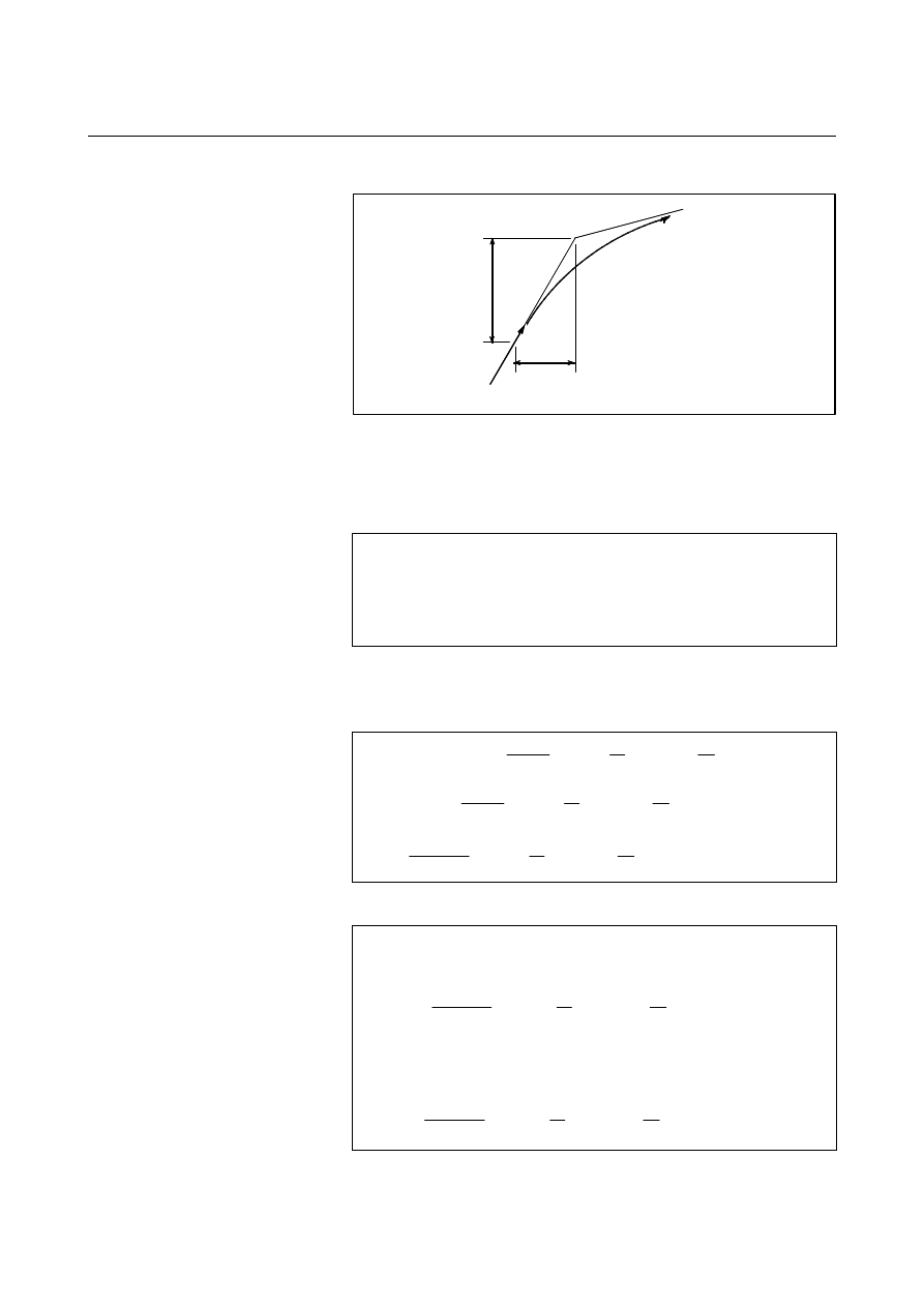
  - Initial value calculation 

Y

0

X

0

V

0


Fig. E.3 (c)    Initial value 

 
The initial value when cornering begins, that is, the X and Y 
coordinates at the end of command distribution by the controller, is 
determined by the feedrate and the positioning system time constant of 
the servo motor. 


T

1

 :  Exponential  acceleration/deceleration time constant. (T=0) 

T

2

 :  Time constant of positioning system (Inverse of position loop gain) 


  - Analysis of corner tool path 

The equations below represent the feedrate for the corner section in 
X-axis direction and Y-axis direction. 


Therefore, the coordinates of the tool path at time t are calculated from 
the following equations: 


)

T

T

(

V

X

X

2

1

1

0

+

=

)

T

T

(

V

Y

Y

2

1

1

0

+

=

]

V

)}

T

t

exp(

T

)

T

t

exp(

T

{

T

T

V

)[

V

V

(

V

X

X

X

X

)

t

(

X

1

2

2

1

1

2

1

1

1

2

1

+

=

)}]

T

t

exp(

T

)

T

t

exp(

T

{

T

T

V

[

V

X

X

2

2

1

1

2

1

1

2

1

=

2

2

2

1

1

2

1

2

1

Y

Y

Y

)

t

(

Y

V

)}

T

t

exp(

T

)

T

t

exp(

T

{

T

T

V

V

V

+

=

0

1

0

X

dt

)

t

(

V

)

t

(

X

X

=

)

t

T

T

(

V

)}

T

t

exp(

T

)

T

t

exp(

T

{

T

T

V

V

X

X

X

+

=

2

1

2

2

2

2

1

2

1

2

1

1

2

0

1

0

Y

dt

)

t

(

V

)

t

(

Y

Y

=

)

t

T

T

(

V

)}

T

t

exp(

T

)

T

t

exp(

T

{

T

T

V

V

Y

Y

Y

+

=

2

1

2

2

2

2

1

2

1

2

1

1

2

B-63944EN/03

 APPENDIX 

E.NOMOGRAPHS


- 2309 - 

E.4 

RADIUS DIRECTION ERROR AT CIRCLE CUTTING 

 
When a servo motor is used, the positioning system causes an error 
between input commands and output results. Since the tool advances 
along the specified segment, an error is not produced in linear 
interpolation. In circular interpolation, however, radial errors may be 
produced, sepecially for circular cutting at high speeds. 
This error can be obtained as follows: 
 

Command path 

Actual path 

r

Y

r


  . . . . . (1) 

r :  Maximum radius error (mm) 

v : Feedrate (mm/sec) 
r  :  Circle radius (mm) 
T

1

 :  Exponential  acceleration/deceleration time constantat cutting (sec) 

(T=0) 

T

2

 :  Time constant of positoning system (sec)   

    (Inverse of positon loop gain) 

α

  :  Feed forward coefficient (%) 

 
In the case of bell-shaped acceleration/deceleration and linear 
acceleration/deceleration after cutting feed interpolation, an approximation 
of this radius error can be obtained with the following expression: 
 
Linear acceleration/deceleration after cutting feed interpolation 
 
 
Bell-shaped acceleration/deceleration after cutting feed interpolation 
 
 
Thus, the radius error in the case of bell-shaped acceleration/deceleration 
and linear acceleration/deceleration after interpolation is smaller than in 
case of exponential acceleration/deceleration by a factor of 12, excluding 
any error caused by a servo loop time constant. 

 
Since the machining radius r (mm) and allowable error 

r  (mm) of 

the workpiece is given in actual machining, the allowable limit 
feedrate v (mm /sec) is determined by equation (1). 
Since the acceleration/deceleration time constant at cutting which is 
set by this equipment varies with the machine tool, refer to the manual 
issued by the machine tool builder. 

r

V

))

-

(1

T

(T

2

1

r

2

2

2

2

2

1

α

+

=

r

V

))

-

(1

T

2

1

T

24

1

(

r

2

2

2

2

2

1

α

+

=

r

V

))

-

(1

T

2

1

T

48

1

(

r

2

2

2

2

2

1

α

+

=

 APPENDIX 

B-63944EN/03


- 2310 - 

F. SETTINGS AT POWER-ON, 

IN THE CLEAR STATE, OR 
IN THE RESET STATE 

SETTINGS AT POWER-ON, IN THE 
CLEAR STATE, OR IN THE RESET 
STATE  


B-63944EN/03

 APPENDIX 


- 2311 - 

F.SETTINGS AT POWER-ON, IN 

THE CLEAR STATE, OR IN THE 

RESET STATE

Either the clear state or reset state is entered during a reset is set by bit 
6 (CLR) of parameter No. 3402 (0: reset state/1: clear state). 
The symbols in the figure below have the following meanings.   
 

 : The setting remains unchanged or the operation continues. 


× : The setting is deleted or the operation stops.   


Item 

Power-on 

Clear state 

Reset state 

Offset 


Set data   


Settings 

Parameter 


Program in memory 


Information of the block 
read in advance during 
automatic operation 

× × × 

N (sequence number) 

× (Note 7) 

× (Notes 1, 2, 7) 

 (Note 1, 2) 

One-shot G code 

× 

× 

× 

Modal G code 

Initial value (Note 3) 
G20 and G21 are set to the 
state at the previous 
power-off. 

Initial value (Note 3) 
G20 and G21 are not 
changed (Note 2). 

 (Note 2 and 6) 

F 0 

 (Note 2) 

S, T, M 

× 

 (Note 2) 

 (Note 2) 

Various 
data 
items 

K (count specification) 

× 

× 

× 

Coordin
ate 

Workpiece coordinates 

0 (Note 4) 


Movement 

× × × 

Dwell 

× × × 

M, S, T code output   

× 

× 

× 

Tool position 
compensation  

× 

See "Tool Position 
Compensation at a Reset". 

See "Tool Position 
Compensation at a Reset".

Tool length compensation 

× 

Depending on the setting of 
bit 6 (LVK) of parameter 
No. 5003 

Depending on the setting of 
bit 6 (LVK) of parameter 
No. 5003 

Tool radius/tool nose 
radius compensation 

× × × 

Operati
on 
during 
executi
on 

Storing a called 
subprogram 

× 

× 

(Note 5)


× 

CNC alarm signal AL 

"0”(when no alarm cause is 
present) 

“0”  (when no alarm cause 
is present) 

“0”  (when no alarm cause 
is present) 

Reference position return 
completion signal ZPx 

× 

 (or × for emergency stop) 

(or × for emergency stop)

S, T, B codes 

× 


code 

× × × 

M, S, T, B strobe signals   

× 

× 

× 

Spindle rotation signal   
(S analog signal) 

× 


CNC ready signal MA 

“1” 


Servo ready signal SA 

“1” 

(when a servo alarm does 

not occur) 

“1” 

(when a servo alarm does 

not occur) 

“1” 

(when a servo alarm does 

not occur) 

Cycle start signal STL 

× 

× 

× 

Output 
signals 

Feed hold signal SPL 

× 

× 

× 

 APPENDIX 

B-63944EN/03


- 2312 - 

F. SETTINGS AT POWER-ON, 

IN THE CLEAR STATE, OR 
IN THE RESET STATE 

Tool position compensation at a reset 
 

 : Cancelled.   


× : Not canceled.   

Bit 3 (LVC) of parameter No. 5006 and bit 7 (TGC) of parameter 

No. 5003 


Compensation method 

LVC=0 

TGC=0 

LVC=1 

TGC=0 

LVC=0 

TGC=1 

LVC=1 

TGC=1 

Wear compensation   

Tool movement 

Geometry compensation 

× 


(Axis movement)

× 


(Axis movement)

Wear compensation 

× 

 × 


Coordinate shift 

Geometry compensation 

× 

× 


NOTES 

1  When the beginning position is found, the main program number is displayed.   
2  If a reset is made during execution of a block, the states of the modal G code and 

modal address (such as N, F, S, T, or M) specified in the block are not reflected.   
The modal information specified in the previous and preceding blocks is kept. 

3  The initial value of the modal G code depends on the following parameters.    For 

details, refer to the parameter manual (B-63950). 
-  Parameter G01 (No.3402#0) 
-  Parameter G18 (No.3402#1) 
-  Parameter G19 (No.3402#2) 
-  Parameter G91 (No.3402#3) 
-  Parameter G23 (No.3402#7) 
-    Parameters No. 3406 to No. 3409 

4  For detection of an absolute position, the value is generated from machine 

coordinates and a workpiece origin offset. 

5  When a reset is made during execution of a subprogram, a return to the main 

program is performed.    Execution at a midpoint in the subprogram is impossible. 

6  When one of the following two settings, which hold the modal G code in group 1 by 

a reset is set: 
-    Reset state (bit 6 of parameter No. 3402 is 0) 
-    Clear state (bit 1 of parameter No. 3402 is 1) and 
    the modal G code in group 1 is held at a time of a reset (bit 1 of parameter No. 
3406 is 1), 
if a reset is made during execution of one of the following canned cycles, which 
cause cycle operation, the mode of the modal G code in group 1 is changed to the 
G01 mode. 
-    G90 : Outer surface/inner surface turning cycle 
-    G92 : Threading cycle 
-    G94 : Edge turning cycle 

7  When bit 0 (SEK) of parameter No. 11353 is set to 1, sequence number N can be 

held even at power-on or in the clear state. 


B-63944EN/03

 APPENDIX 


- 2313 - 

G.CHARACTER-TO-CODES

CORRESPONDENCE TABLE

CHARACTER-TO-CODES 
CORRESPONDENCE TABLE 

 
Appendix G, "CHARACTER-TO-CODES CORRESPONDENCE 
TABLE", consists of the following sections: 
 
G.1  CHARACTER-TO-CODES CORRESPONDENCE TABLE 2314 
G.2  FANUC DOUBLE-BYTE CHARACTER CODE TABLE....2315 
 

 APPENDIX 

B-63944EN/03


- 2314 - 

G. CHARACTER-TO-CODES 

CORRESPONDENCE 

G.1 

CHARACTER-TO-CODES CORRESPONDENCE TABLE 


Character Code 

Comment 

Character

Code

Comment 

A 065 


6  054 


B 066 


7  055 


C 067 


8  056 


D 068 


9  057 


E 069 


  032 

Space 

F 070 


!  033 

Exclamation 

mark 

G 071 


”  034 

Quotation 

mark 

H 072 


#  035 

Sharp 

I 073 


$ 036 

Dollar 

sign 

J 074 


% 037 

Percent 

K 075 


&  038 

Ampersand 

L 076 


’  039 

Apostrophe 

M 077 


(  040 

Left 

parenthesis 

N 078 


)  041 

Right 

parenthesis 

O 079 


*  042 

Asterisk 

P 080 


+  043 

Plus 

sign 

Q 081 


,  044 

Comma 

R 082 


-  045 

Minus 

sign 

S 083 


.  046 

Period 

T 084 


/  047 

Slash 

U 085 


:  058 

Colon 

V 086 


;  059 

Semicolon 

W 087 


<  060 

Left 

angle bracket 

X 088 


=  061 

Equal 

sign 

Y 089 


>  062 

Right 

angle bracket 

Z 090 


?  063 

Question 

mark 

0 048 


@ 064 

At 

mark 

1 049 


[  091 

Left 

square bracket 

2 050 


]  093 

Right 

square bracket 

3 051 


^  094 


4 052 


_  095 

Underscore 

5 053 


B-63944EN/03

 APPENDIX 


- 2315 - 

G.CHARACTER-TO-CODES

CORRESPONDENCE TABLE

G.2 

FANUC DOUBLE-BYTE CHARACTER CODE TABLE 


Content      ..     292      293      294      295     ..