FANUC Series 30i/300i/300is-MODEL A. Machining Center System. User's manual - page 292
 

  Index      Manuals     FANUC Series 30i/300i/300is-MODEL A. Machining Center System. User's manual (B-63944EN/03)


Search            copyright infringement  


Content      ..     290      291      292      293     ..


FANUC Series 30i/300i/300is-MODEL A. Machining Center System. User's manual - page 292


 APPENDIX 

B-63944EN/03


- 2292 - 

C. LIST OF FUNCTIONS AND 

PROGRAM FORMAT 

(6/11) 

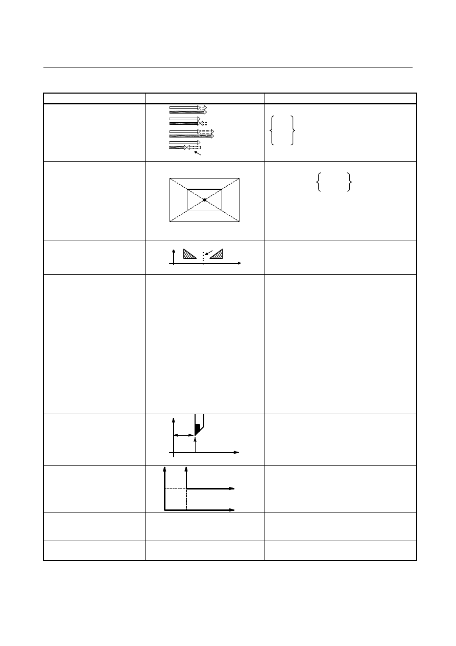
Functions Illustration 

Program 

format 

Tool offset 
(G45 to G48) 

G 45

G 46

G 47

G 48

Increase

Decrease

Double decrease

Double increase

Offset amount

IP

IP

 For machining center 

IP

_ D_ ;

G45

G46

G47

G48


D : Tool offset number 

Scaling 
(G50, G51) 

P

1'

P1

P

2

P

4

P

3

P

2'

P

4'

P

3

'

IP


 For machining center 

G51 X_ Y_ Z_      P_

I_ J_ K_

;


P, I, J, K : Scaling magnification 
X, Y, Z : Control position of scaling 
G50 : Cancel 

 For lathe only


Enabled when G code system B/C is used 

Programmable mirror image 
(G50.1, G51.1) 

Mirror

IP


G51.1 

IP

_ ;   

G50.1 ; . . . Cancel 

Synchronous, composite, and 
superimposed control by 
program command 
(G50.4, G51.4, G50.5, G51.5, 
G50.6, G51.6) 


G51.4 P_Q_(L_) ; Start synchronous control (L_ 
can be omitted.) 
G50.4 Q_ ; Cancel synchronous control. 
P : Number to identify synchronous master axis
Q : Number to identify synchronous slave axis 
L : Parking start command   
G51.5 P_Q_ ; Start composite control 
G50.5 P_Q_ ; Cancel composite control 
P : Number to identify composite axis 1 
Q : Number to identify composite axis 2 
G51.6 P_Q_ ;  Start superimposed control 
G50.6 Q_ ; Cancel superimposed control 
P : Number to identify superimposed master 

axis 

Q : Number to identify superimposed slave axis

Coordinate system setting 
Maximum spindle speed clamp
(G50) 

X

Z


 For lathe only


G50 

IP

_ ;    (Coordinate system setting) 

 
G50 S_ ;    (Maximum spindle speed clamp)


Local coordinate system setting 
(G52) 

x

y

Local coordinate
system

Workpiece
coordinate system

IP


G52 

IP

_ ; 

Command in machine 
coordinate system 
(G53) 


G53 

IP

_ ; 

Tool axis direction control 
(G53.1) 


G53.1 ; Tool axis direction control


B-63944EN/03

 APPENDIX 


- 2293 - 

C.LIST OF FUNCTIONS AND

PROGRAM FORMAT

(7/11) 

Functions Illustration 

Program 

format 

Selection of workpiece 
coordinate system 
(G54 to G59) 

Workpiece coordinate system

Workpiece
origin
offset

I

P

Machine coordinate system

G54

:

:

IP

_ ;

G59


Rotary table dynamic fixture 
offset 
(G54.2) 

X

Y

X

Y

X

Y

F0

F

θ

0

θ

Z

W

Machine coordinate
system origin

W      : Workpiece origin offset value

θ

0   : Reference angle

F0      : Reference fixture offset value

θ

    : Rotation axis angle

  : Fixture offset value

C

Rotation axis

center

 For machining center 

G54.2 P_ ;    Fixture offset   
P : Reference fixture offset value number 
G54.2 P0 ;    Offset cancel 

Workpiece setting error 
compensation 
(G54.4) 


X

x, y, z 

a

b


  x :  X-axis direction error 
  y :  Y-axis direction error 
  z :  Z-axis direction error 
  a :  Rotation direction error (about 

the X-axis) 

  b :  Rotation direction error (about 

the Y-axis) 

  c :  Rotation direction error (about 

the Z-axis) 

G54.4 P_ ; Workpiece setting error 

compensation  

P : Workpiece setting error number   
G54.4 P0 ; Workpiece setting error 

compensation cancel


Single direction positioning 
(G60) 

IP


G60 

IP

_ ; 

Cutting mode (G64) 
Exact stop mode (G61) 
Tapping mode (G63) 

v

t

G64


G64_ ;  Cutting mode 
G61_ ;    Exact stop mode 
G63_ ;  Tapping mode 

Automatic corner override 
(G62) 

v

G61

t


G62_ ;    Automatic corner override   

Custom macro 
(G65, G66, G66.1, G67) 

G65 P_L_ ;

O_ ;

M99 ;

Macro


One-shot call 
    G65 P_ L_ <Argument assignment> ; 
    P : Program number 
    L : Number of repetition 
Modal call 
    G66 P_ L_ <Argument assignment> ; 
    Call after the move command 
    G66.1 P_ L_ <Argument assignment> ; 
    Each block call 
  G67 ; Cancel 

 APPENDIX 

B-63944EN/03


- 2294 - 

C. LIST OF FUNCTIONS AND 

PROGRAM FORMAT 

(8/11) 

Functions Illustration 

Program 

format 

Mirror image for double turret 
(G68, G69) 


 For lathe only


G68 : Mirror image for double turret 
 
G69 : Mirror image cancel 

Coordinate system rotation, 
Three-dimensional coordinate 
conversion 
(G68, G69) 
(G68.1, G69.1) 

Y

X

(x y)

α


In case of X-Y plane 

 For machining center 

G68

G17 X_ Y_
G18 Z_ X_

G19 Y_ Z_

α

 ;


G69 ;  Cancel 

 For lathe 

G68.1

G17 X_ Y_
G18 Z_ X_

G19 Y_ Z_

α

 ;


G69.1 ;  Cancel 

Tilted working plane command
(G68.2) 


G68.2 X_ Y_ Z_ I_ J_ K_    ;     
Tilted working plane command 
G69 ; Tilted working plane command cancel 
X, Y, Z : Feature coordinate system origin 
I, J, K    : Euler angles for determining the 
orientation of the feature coordinate system 

Tilted working plane command 
with guidance 
(G68.2, G68.4) 


G68.2/G68.4 P_ X_ Y_ Z_ I_ J_ K_    ;     
G68.2 : Tilted working plane command 
G68.4 : Tilted working plane command 

(incremental multiplexed command) 

G69 ; Tilted working plane command cancel 
Without P : Euler's angle   
P1 

: Roll, pitch, yaw 

P2 

: Three points   

P3 

: Two vectors   

P4 

: Projection angle   

Angular surface command by 
tool axis direction (G68.3) 

Xc

Yc 

Zc 

Feature coordinate system Xc-Yc-Zc

R

G68.3 X_ Y_ Z_ R_    ;     
G69 ;  Cancel 
X,Y, Z :  Feature coordinate system origin 

:  Feature coordinate system rotation 

angle about the Z-axis 

B-63944EN/03

 APPENDIX 


- 2295 - 

C.LIST OF FUNCTIONS AND

PROGRAM FORMAT

(9//11) 

Functions Illustration 

Program 

format 

Figure copy 
 (G72.1, G72.2) 

Y

P1

P0

Start point

60°

X


Start point P0

P1

X

Y

Rotational copy 

G72.1

X_ Y_
Z_ X_

Y_ Z_

R_ ;

P_ L_

(G17)
(G18)

(G19)


Linear copy 

G72.2

I_ J_
K_ I_

J_ K_

;

P_ L_

(G17)
(G18)

(G19)


Canned cycle for drilling 
(G73, G74, G80 to G89) 


 For machining center 

G80 ;  Cancel 
G73 
G74 
G76 
G81 
 : 
G89 

Canned cycle 
(G71 to G76) 
(G90, G92, G94) 


 For lathe only


N   G70P  Q  ; 
G71U   R  ; 
G71P   Q  U  W  F  S  T  ; 
G72W   R  ; 
G72P   Q  U  W  F  S  T  ; 
G73U   W  R  ; 
G73P   Q  U  W  F  S  T  ; 
G74R   ; 
G74X(u)   Z(w)  P  Q  R  F  ; 
G75R   ;  
G75X(u)   Z(w )  P  Q  R  F  ; 
G76P   Q  R  ; 
G76X(u)   Z(w)  P  Q  R  F  ; 

G90
G92

X_ Z_ I_ F_ ;


G94X   Z  K  F   ;


Canned grinding cycle (for 
grinding machine) 
(G71 to G75, G77 to G79) 


 For machining center 

G75 I_ J_ K_ 

α

_ R_ F_ P_ L_ ; 

G77 I_ J_ K_ 

α

_ R_ F_ P_ L_ ; 

G78 I_ (J_) K_ 

α

_ F_ P_ L_ ; 

G79 I_ J_ K_ 

α

_ R_ F_ P_ L_ ; 

α

 : Arbitrary axis address of the grinding axis 


 For lathe


G71 A_ B_ W_ U_ I_ K_ H_ ; 
G72 P_ A_ B_ W_ U_ I_ K_ H_ ; 
G73 A_ (B_) W_ U_ K_ H_ ; 
G74 P_ A_ (B_) W_ U_ K_ H_ ; 

X_Y_Z_P_Q_R_F_K_ ; 

 APPENDIX 

B-63944EN/03


- 2296 - 

C. LIST OF FUNCTIONS AND 

PROGRAM FORMAT 

(10/11) 

Functions Illustration 

Program 

format 

Absolute/incremental 
programming 
(G90/G91) 


 For machining center 

G90_ ;  Absolute programming 
G91_ ;  Incremental programming 
 : 
G90_ G91_ ; Programming in both modes 
 

 For lathe


: Absolute programming 


: Incremental programming 

    Distinguished by an address specified in 
    combined use with a G function such as G00
  and G01. 

Maximum incremental command 
value check (G91.1) 


G91.1 

IP

_ ;   

IP

_ ; Maximum incremental value 

Set 0 to cancel maximum incremental value 
check. 

Change of workpiece 
coordinate system (G92) 
Maximum spindle speed clamp 
(G92) 

IP


 For machining center 

G92 

IP

_ ; Change of workpiece coordinate 

system 

G92 S_ ; Constant surface speed control : 

Maximum spindle speed clamp 

Workpiece coordinate system 
preset 
(G92.1) 


 For machining center 

G92.1 

IP

 0 ;   

Inverse time feed 
(G93) 


G93 ; Inverse time setting mode 

Feed per minute,   
Feed per revolution   
(G94, G95) 
 

(G98, G99) 

mm/min inch/min 
mm/rev inch/rev 

 For machining center 

G94 F_ ; Feed per minute 
G95 F_ ; Feed per revolution 
 

 For lathe


G98 F_ ; Feed per minute 
G99 F_ ; Feed per revolution 

Constant surface speed control
(G96, G97) 

Surface speed (m/min or feet/min)

Spindle

speed
N(min

-1

)


G96 S_ ;   Constant surface speed control on 

(surface speed specification) 

G97 S_ ;   Constant surface speed control off 

(spindle speed specification) 


B-63944EN/03

 APPENDIX 


- 2297 - 

C.LIST OF FUNCTIONS AND

PROGRAM FORMAT

(11/11) 

Functions Illustration 

Program 

format 

Speed display function of a 
milling tool with servo motor 
(G96.1,G96.2,G96.3,G96.4) 


G96.1 P_R_; The next block starts operating 

upon completion of spindle 
indexing (the SV speed control 
mode is off). 

G96.2 P_R_; The next block starts operating 

without waiting for spindle 
indexing to complete. 

G96.3 P_; 

The next block starts operating 
after confirming the completion of 
spindle indexing (the SV speed 
control mode is off). 

G96.4 P_; 

The SV speed control mode is on.

Initial point return / R point 
return 
(G98, G99) 

G99

G98

Initial level

R level

Z point


 For machining center 

G98_ ; 
G99_ ; 

Optional chamfering/corner R 

K

I

R


 For machining center 

,C_ : Chamfering 
,R_ : Corner R 


Chamfering/corner R 


 For lathe only


C

±

X_   

P_; 

 R_ 


C

±

Z_   

P_; 

 R_ 

In-feed control (for grinding 
machine) 
(G160, G161) 


 For machining center


G161 R_ ; 


G160 ; 


Figure program (G01, G02, G03)

D.RANGE OF COMMAND VALUE

 APPENDIX 

B-63944EN/03


- 2298 - 

RANGE OF COMMAND VALUE 


Linear axis 

  - In case of millimeter input, feed screw is millimeter 

Increment system 


IS-A  

IS-B  

IS-C  

IS-D  

IS-E  

Least input increment (mm)  0.01 

0.001 

0.0001 

0.00001 

0.000001 

Least command increment 
(mm) 

0.01 0.001 

0.0001 

0.00001 

0.000001 

Max. programmable 
dimension (mm) 

±

999,999.99 

±

999,999.999 

±

99,999.9999 

±

9,999.99999 

±

999.999999 

Max. rapid traverse 
(mm/min)

*1


999,000 999,000 100,000 10,000  1,000 

Feedrate range (mm/min)

*1


0.01 to 999,000 

0.01 to 999,000 

0.0001 to 100,000  0.00001 to 10,000  0.000001 to 1,000

Incremental feed (mm/step) 

0.01 
0.1 
1.0 
10.0 

0.001 
0.01 
0.1 
1.0 

0.0001 
0.001 
0.01 
0.1 

0.00001 
0.0001 
0.001 
0.01 

0.000001 
0.00001 
0.0001 
0.001 

Tool compensation amount 
(mm)

*2


0 to 

±

9,999.99 0 

to 

±

9,999.999 0 

to 

±

9,999.9999 0 

to 

±

9,999.99999 0 

to 

±

999.999999 

Backlash compensation 
amount (pulses)

*3


0 to 

±

9,999 0 

to 

±

9,999 0 

to 

±

9,999 0 

to 

±

9,999 0 

to 

±

9,999 

Dwell (sec)

*4


0 to 999,999.99 

0 to 999,999.999 

0 to 99,999.9999 

0 to 9,999.99999 

0 to 999.999999 


  - In case of inch input, feed screw is millimeter 

Increment system 


IS-A IS-B IS-C IS-D IS-E 

Least input increment (inch)  0.001 

0.0001 

0.00001 

0.000001 

0.0000001 

Least command increment 
(inch) 

0.001 0.0001 

0.00001 

0.000001 

0.0000001 

Max. programmable 
dimension (inch) 

±

39,370.078 

±

39,370.0787 

±

3,937.00787 

±

393.700787 

±

39.3700787 

Max. rapid traverse 
(mm/min)

*1


999,000 999,000 100,000 10,000  1,000 

Feedrate range (inch/min)

*1

  0.001 to 96,000 

0.0001 to 9,600 

0.00001 to 4,000 

0.000001 to 400 

0.0000001 to 40 

Incremental feed (inch/step)   

0.001 
0.01 
0.1 
1.0 

0.0001 
0.001 
0.01 
0.1 

0.00001 
0.0001 
0.001 
0.01 

0.000001 
0.00001 
0.0001 
0.001 

0.0000001 
0.000001 
0.00001 
0.0001 

Tool compensation amount 
(inch)

*2


0 to 

±

999.999 0 

to 

±

999.9999 0 

to 

±

999.99999 0 

to 

±

999.999999 0 

to 

±

99.9999999 

Backlash compensation 
amount (pulses)

*3


0 to 

±

9,999 0 

to 

±

9,999 0 

to 

±

9,999 0 

to 

±

9,999 0 

to 

±

9,999 

Dwell (sec)

*4


0 to 999,999.99 

0 to 999,999.999 

0 to 99,999.9999 

0 to 9,999.99999 

0 to 999.999999 


B-63944EN/03

 APPENDIX 

D.RANGE OF COMMAND VALUE


- 2299 - 

  - In case of inch input, feed screw is inch 

Increment system 


IS-A IS-B IS-C IS-D IS-E 

Least input increment (inch)  0.001 

0.0001 

0.00001 

0.000001 

0.0000001 

Least command increment 
(inch) 

0.001 0.0001 

0.00001 

0.000001 

0.0000001 

Max. programmable 
dimension (inch) 

±

99,999.999 

±

99,999.9999 

±

9,999.99999 

±

999.999999 

±

99.9999999 

Max. rapid traverse 
(inch/min)

*1


96,000 9,600  4,000  400 

40 

Feedrate range (inch/min)

*1

  0.001 to 96,000 

0.0001 to 9,600 

0.00001 to 4,000 

0.000001 to 400 

0.0000001 to 40 

Incremental feed (inch/step)   

0.001 
0.01 
0.1 
1.0 

0.0001 
0.001 
0.01 
0.1 

0.00001 
0.0001 
0.001 
0.01 

0.000001 
0.00001 
0.0001 
0.001 

0.0000001 
0.000001 
0.00001 
0.0001 

Tool compensation amount 
(inch)

*4


0 to 

±

999.999 0 

to 

±

999.9999 0 

to 

±

999.99999 0 

to 

±

999.999999 0 

to 

±

99.9999999 

Backlash compensation 
amount (pulses)

*3


0 to 

±

9,999 0 

to 

±

9,999 0 

to 

±

9,999 0 

to 

±

9,999 0 

to 

±

9,999 

Dwell (sec)

*4


0 to 999,999.99 

0 to 999,999.999 

0 to 99,999.9999 

0 to 9,999.99999 

0 to 999.999999 


  - In case of millimeter input, feed screw is inch 

Increment system 


IS-A IS-B IS-C IS-D IS-E 

Least input increment (mm)  0.01 

0.001 

0.0001 

0.00001 

0.000001 

Least command increment 
(mm) 

0.01 0.001 

0.0001 

0.00001 

0.000001 

Max. programmable 
dimension (mm) 

±

999,999.99 

±

999,999.999 

±

99,999.9999 

±

9,999.99999 

±

999.999999 

Max. rapid traverse 
(inch/min)

*1


96,000 9,600  4,000  400 

40 

Feedrate range (mm/min)

*1


0.01 to 999,000 

0.001 to 999,000 

0.0001 to 100,000  0.00001 to 10,000  0.000001 to 1,000

Incremental feed (mm/step)   

0.01 
0.1 
1.0 
10.0 

0.001 
0.01 
0.1 
1.0 

0.0001 
0.001 
0.01 
0.1 

0.00001 
0.0001 
0.001 
0.01 

0.000001 
0.00001 
0.0001 
0.001 

Tool compensation amount 
(mm)

*2


0 to 

±

9,999.99 0 

to 

±

9,999.999 0 

to 

±

9,999.9999 0 

to 

±

9,999.99999 0 

to 

±

999.999999 

Backlash compensation 
amount (pulses)

*3


0 to 

±

9,999 0 

to 

±

9,999 0 

to 

±

9,999 0 

to 

±

9,999 0 

to 

±

9,999 

Dwell (sec)

*4


0 to 999,999.99 

0 to 999,999.999 

0 to 99,999.9999 

0 to 9,999.99999 

0 to 999.999999 


Content      ..     290      291      292      293     ..