FANUC Series 30i/300i/300is-MODEL A. Machining Center System. User's manual - page 290
 

  Index      Manuals     FANUC Series 30i/300i/300is-MODEL A. Machining Center System. User's manual (B-63944EN/03)


Search            copyright infringement  


Content      ..     288      289      290      291     ..


FANUC Series 30i/300i/300is-MODEL A. Machining Center System. User's manual - page 290


A.PARAMETERS

 APPENDIX 

B-63944EN/03


- 2276 - 

27379 


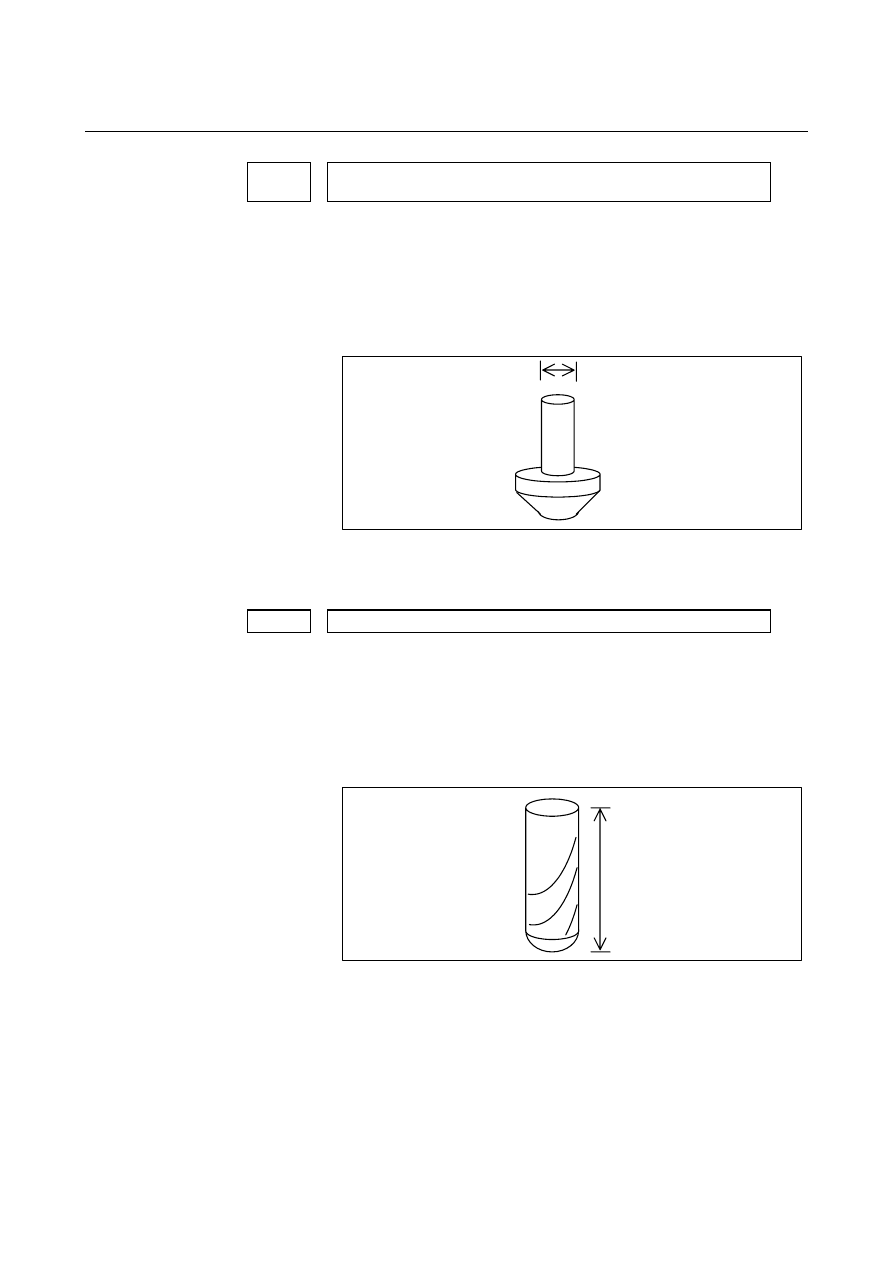
Shank diameter applied when a chamfering tool is drawn in animated 

simulation 


[Input type]  Parameter input 

 [Data 

type] 

2-word 


[Unit of data]  0.001mm (metric input), 0.0001inch (inch input) 

  [Valid data range]  0 or larger 

This parameter sets the shank diameter applied when a chamfering 
tool is drawn in animated simulation. 
 

Shank diameter   


When 0 is set, 32 mm for metric input or 1.2598 inch for inch input is 
assumed. 
 

27380 


Length of cut applied when a ball end mill is drawn in animated simulation


[Input type]  Parameter input 

 [Data 

type] 

2-word 


[Unit of data]  0.001mm (metric input), 0.0001inch (inch input) 

  [Valid data range]  0 or larger 

This parameter sets the length of cut applied when a ball end mill is 
drawn in animated simulation. 
 

Length of cut 


When 0 is set, 50 mm for metric input or 1.9685 inch for inch input is 
assumed. 
 

B-63944EN/03

 APPENDIX 

A.PARAMETERS


- 2277 - 

27381 


Length of cut applied when a reamer is drawn in animated simulation 


[Input type]  Parameter input 

 [Data 

type] 

2-word 


[Unit of data]  0.001mm (metric input), 0.0001inch (inch input) 

  [Valid data range]  0 or larger 

This parameter sets the length of cut applied when a reamer is drawn 
in animated simulation. 
 

Length of cut 


When 0 is set, 50 mm for metric input or 1.9685 inch for inch input is 
assumed. 
 

27382 


Length of cut applied when a boring tool is drawn in animated simulation


[Input type]  Parameter input 

 [Data 

type] 

2-word 


[Unit of data]  0.001mm (metric input), 0.0001inch (inch input) 

  [Valid data range]  0 or larger 

This parameter sets the length of cut applied when a boring tool is 
drawn in animated simulation. 
 

Length of cut 


When 0 is set, 50 mm for metric input or 1.9685 inch for inch input is 
assumed. 
 

A.PARAMETERS

 APPENDIX 

B-63944EN/03


- 2278 - 

27383 


Length of cut applied when a face milling cutter is drawn in animated 

simulation 


[Input type]  Parameter input 

 [Data 

type] 

2-word 


[Unit of data]  0.001mm (metric input), 0.0001inch (inch input) 

  [Valid data range]  0 or larger 

This parameter sets the length of cut applied when a face milling 
cutter is drawn in animated simulation. 
 

Length of cut 


When 0 is set, 63 mm for metric input or 2.4803 inch for inch input is 
assumed. 


#7 #6 #5 #4 #3 #2 #1 #0 

27384 


VRP 


[Input type]  Parameter input 

 [Data 

type] 

Bit 


        # 0 

VRP

  When a multifunction tool is drawn in animated simulation, the tip is: 

0:  Positioned on the front. 
1:  Positioned on the rear. 
 

Front

Rear

Tip


Holder

Holder


B-63944EN/03

 APPENDIX 

A.PARAMETERS


- 2279 - 

27385 


Holder length applied when a multifunction tool is drawn in animated 

simulation 


[Input type]  Parameter input 

 [Data 

type] 

2-word 


[Unit of data]  0.001mm (metric input), 0.0001inch (inch input) 

  [Valid data range]  0 or larger 

This parameter sets the holder length applied when a multifunction 
tool is drawn in animated simulation. 
 

Holder length


Tip


Holder


When 0 is set, 50 mm for metric input or 1.9685 inch for inch input is 
assumed. 
 

27386 


Holder width applied when a multifunction tool is drawn in animated 

simulation 


[Input type]  Parameter input 

 [Data 

type] 

2-word 


[Unit of data]  0.001mm (metric input), 0.0001inch (inch input) 

  [Valid data range]  0 or larger 

This parameter sets the holder width applied when a multifunction 
tool is drawn in animated simulation. 
 

Holder width


Tip


Holder


When 0 is set, 14 mm for metric input or 0.5512 inch for inch input is 
assumed. 


A.PARAMETERS

 APPENDIX 

B-63944EN/03


- 2280 - 

A.2 

DATA TYPE 

 
Parameters are classified by data type as follows: 

Data type 

Valid data range

Remarks 

Bit 
Bit machine group 
Bit path 
Bit axis 
Bit spindle 

0 or 1 


Byte 
Byte machine group 
Byte path 
Byte axis 
Byte spindle 

-128 to 127 

0 to 255 


Some parameters handle 
these types of data as 
unsigned data. 

Word 
Word machine group 
Word path 
Word axis 
Word spindle 

-32768 to 32767 

0 to 65535 

Some parameters handle 
these types of data as 
unsigned data. 

2-word 
2-word machine group 
2-word path 
2-word axis 
2-word spindle 

0 to 

±

999999999

Some parameters handle 
these types of data as 
unsigned data. 

Real 
Real machine group 
Real path 
Real axis 
Real spindle 

See the standard 

parameter setting 

tables. 


NOTE 

1  Each of the parameters of the bit, bit machine group, bit path, bit axis, and bit 

spindle types consists of 8 bits for one data number (parameters with eight different 
meanings). 

2  For machine group types, parameters corresponding to the maximum number of 

machine groups are present, so that independent data can be set for each machine 
group. 

3  For path types, parameters corresponding to the maximum number of paths are 

present, so that independent data can be set for each path. 

4  For axis types, parameters corresponding to the maximum number of control axes 

are present, so that independent data can be set for each control axis. 

5  For spindle types, parameters corresponding to the maximum number of spindles 

are present, so that independent data can be set for each spindle axis. 

6  The valid data range for each data type indicates a general range. The range varies 

according to the parameters. For the valid data range of a specific parameter, see 
the explanation of the parameter.   


B-63944EN/03

 APPENDIX 

A.PARAMETERS


- 2281 - 

A.3 

STANDARD PARAMETER SETTING TABLES 

 
This section defines the standard minimum data units and valid data 
ranges of the CNC parameters of the real type, real machine group 
type, real path type, real axis type, and real spindle type. The data type 
and unit of data of each parameter conform to the specifications of 
each function. 
 

NOTE 

1  Values are rounded up or down to the nearest 

multiples of the minimum data unit. 

2  A valid data range means data input limits, and 

may differ from values representing actual 
performance. 

3  For information on the ranges of commands to the 

CNC, refer to Appendix D, "Range of Command 
Value." 


(A) Length and angle parameters (type 1) 


Unit of data 

Increment

Minimum

Valid data range 

IS-A 0.01 


-999999.99  to 

+999999.99 

IS-B 0.001   

-999999.999 to 

+999999.999 

IS-C 0.0001   

-99999.9999 to 

+99999.9999 

IS-D 0.00001  

-9999.99999 

to 

+9999.99999 

mm 

deg.


IS-E 0.000001 

 -999.999999 

to +999.999999 

IS-A 0.001   

-99999.999 to 

+99999.999 

IS-B 0.0001   

-99999.9999 to 

+99999.9999 

IS-C 0.00001  

-9999.99999 

to 

+9999.99999 

IS-D 0.000001  -999.999999 

to +999.999999 

inch 

IS-E 0.0000001

 -99.9999999 

to  +99.9999999 


(B) Length and angle parameters (type 2) 


Unit of data 

Increment 

system 

Minimum 

data unit

Valid data range 

IS-A 0.01 

 0.00  to 

+999999.99 

IS-B 0.001   0.000 to 

+999999.999 

IS-C 0.0001    0.0000 to 

+99999.9999 

IS-D 0.00001   0.00000 

to 

+9999.99999 

mm 

deg.


IS-E 0.000001 

 0.000000 

to +999.999999 

IS-A 0.001   0.000 to 

+99999.999 

IS-B 0.0001   0.0000 to 

+99999.9999 

IS-C 0.00001   0.00000 

to 

+9999.99999 

IS-D 0.000001   0.000000 

to +999.999999 

inch 

IS-E 0.0000001

 0.0000000 

to  +99.9999999 


A.PARAMETERS

 APPENDIX 

B-63944EN/03


- 2282 - 

(C) Velocity and angular velocity parameters 


Unit of data 

Increment 

system 

Minimum 

data unit

Valid data range 

IS-A 

0.01 

      0.00      to +999000.00 

IS-B 

0.001 

      0.000     to +999000.000 

IS-C 

0.0001 

      0.0000    to  +99999.9999 

IS-D 

0.00001 

      0.00000   to   +9999.99999 

mm/min 

degree/min 

IS-E 

0.000001 

      0.000000  to    +999.999999 

IS-A 

0.001 

      0.000     to  +96000.000 

IS-B 

0.0001 

      0.0000    to   +9600.0000 

IS-C 

0.00001 

      0.00000   to   +4000.00000 

IS-D 

0.000001 

      0.000000  to    +400.000000 

inch/min 

IS-E 

0.0000001

      0.0000000 to     +40.0000000 


(D)Acceleration and angular acceleration parameters 


Unit of data 

Increment 

system 

Minimum 

data unit

Valid data range 

IS-A 0.01 


0.00 

to 

+999999.99 

IS-B 0.001   

0.000  to 

+999999.999 

IS-C 0.0001   

0.0000  to 

+99999.9999 

IS-D 0.00001  

0.00000 to 

+9999.99999 

mm/sec

2


deg./sec

2


IS-E 0.000001 


0.000000 

to +999.999999 

IS-A 0.001   

0.000  to 

+99999.999 

IS-B 0.0001   

0.0000  to 

+99999.9999 

IS-C 0.00001  

0.00000 to 

+9999.99999 

IS-D 0.000001  

0.000000 

to +999.999999 

inch/sec

2


IS-E 0.0000001


0.0000000 

to  +99.9999999 


B-63944EN/03

 APPENDIX 

B.PROGRAM CODE LIST


- 2283 - 

PROGRAM CODE LIST 


ISO code 

EIA code 

Custom macro 

Character name 

Character 

Code 

(hexadecimal)

Character

Code 

(hexadecimal)

without 

custom 

macro 

with 

custom 

macro 

Usable as file 

name 

Number 

0 30 0 20    * 

Number 

1 B1 1 01     * 

Number 

2 B2 2 02     * 

Number 

3 33 3 13    * 

Number 

4 B4 4 04     * 

Number 

5 35 5 15    * 

Number 

6 36 6 16    * 

Number 

7 B7 7 07     * 

Number 

8 B8 8 08     * 

Number 

9 39 9 19    * 

Address A 

41 

61 


Address B 

42 

62 


Address C 

C3 

73 


Address D 

44 

64 


Address E 

C5 

75 


Address F 

C6 

76 


Address G 

47 

67 


Address H 

48 

68 


Address 

I C9 i 79    * 

Address J 

CA 

51 


Address K 

4B 

52 


Address L 

CC 

43 


Address 

M 4D m 54     * 

Address N 

4E 

45 


Address O 

CF 

46 


Address P 

50 

57 


Address Q 

D1 

58 


Address R 

D2 

49 


Address S 

53 

32 


Address T 

D4 

23 


Address U 

55 

34 


Address V 

56 

25 


Address W 

D7 

26 


Address X 

D8 

37 


Address Y 

59 

38 


Address Z 

5A 

29 


Delete DEL 

FF 

Del 

7F 


Back 

space 

BS 88 BS 2A   


Tabulator HT 

09 

Tab 

2E 


End of block 

LF or NL 

0A 

CR or EOB

80 


Carriage return 

CR 

8D 


Content      ..     288      289      290      291     ..