FANUC Series 30i/300i/300is-MODEL A. Machining Center System. User's manual - page 258
 

  Index      Manuals     FANUC Series 30i/300i/300is-MODEL A. Machining Center System. User's manual (B-63944EN/03)


Search            copyright infringement  


Content      ..     256      257      258      259     ..


FANUC Series 30i/300i/300is-MODEL A. Machining Center System. User's manual - page 258


A.PARAMETERS

 APPENDIX 

B-63944EN/03


- 2020 - 


1772 


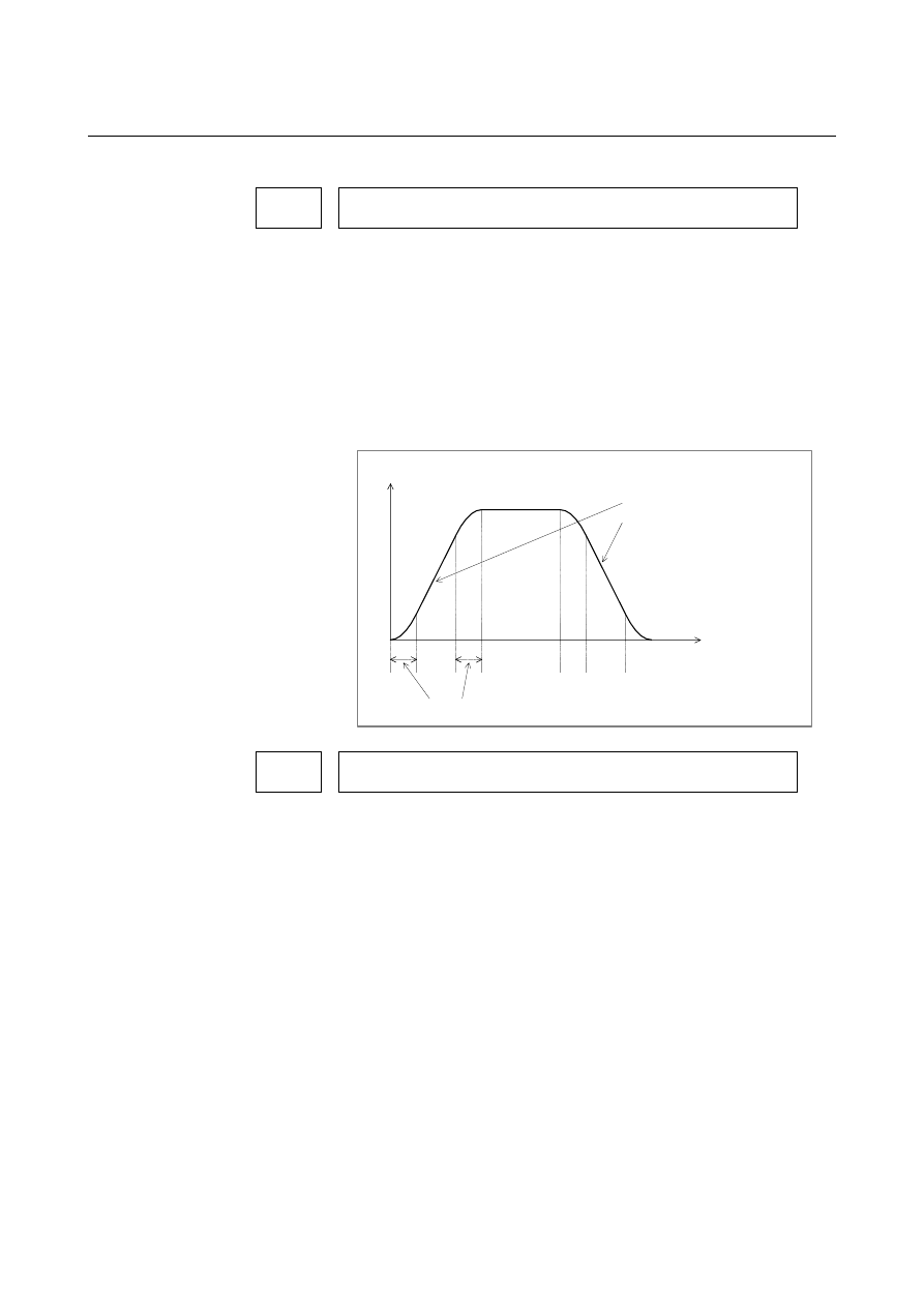
Acceleration change time of bell-shaped acceleration/deceleration before 

interpolation 


[Input type]  Parameter input 


[Data type]  2-word path 


[Unit of data]  msec 

  [Valid data range]  0 to 200 

Set an acceleration change time of bell-shaped acceleration/ 
deceleration before interpolation (time for changing from the state of 
constant feedrate (A) to the state of constant acceleration/deceleration 
(C) at the acceleration rate calculated from the acceleration rate set in 
parameter No. 1660: time of (B) in the figure below). 


Feedrate in tangent direction 

Optimum inclination is 
automatically calculated from the 
setting of parameter No. 1660. 

Time set by parameter No. 1772 

(A) (B)

(B)

(B)

(B)

(A)

(A) 

(C)

(C)


1783 

  Maximum allowable feedrate difference for feedrate determination based on 

corner feedrate difference 


[Input type]  Parameter input 


[Data type]  Real axis 


[Unit of data]  mm/min, inch/min, degree/min (machine unit) 


[Minimum unit of data]  Depend on the increment system of the applied axis 

  [Valid data range]  Refer to the standard parameter setting table (C) 

(When the increment system is IS-B, 0.0 to +999000.0) 
If a feedrate component change for each axis exceeding the value set 
in this parameter occurs at the joint of blocks, the feedrate 
determination function based on corner feedrate difference finds a 
feedrate not exceeding the set value and performs deceleration by 
using acceleration/deceleration before interpolation. Thus, a shock to 
the machine and machining error at a corner can be reduced. 
 

B-63944EN/03

 APPENDIX 

A.PARAMETERS


- 2021 - 

1788 


Maximum allowable acceleration change rate in feedrate determination 

based on acceleration change for each axis 


[Input type]  Parameter input 


[Data type]  Real axis 


[Unit of data]  mm/sec

2

, inch/sec

2

, degree/sec

2

 (machine unit) 


[Minimum unit of data]  Depend on the increment system of the applied axis 

  [Valid data range]  Refer to the standard parameter setting table (D) 

(When the machine system is metric system, 0.0 to +100000.0. When 
the machine system is inch system, machine, 0.0 to +10000.0.) 
Set a maximum allowable acceleration change rate for each axis in 
feedrate control based on acceleration change under control on the rate 
of change of acceleration. 
For an axis with 0 set in this parameter, feedrate control based on 
acceleration change is disabled. 
If 0 is set for all axes, feedrate control based on acceleration change is 
not exercised. 
 

1789 


Maximum allowable acceleration change rate in feedrate determination 

based on acceleration change for each axis (linear interpolation) 


[Input type]  Parameter input 


[Data type]  Real axis 


[Unit of data]  mm/sec

2

, inch/sec

2

, degree/sec

2

 (machine unit) 


[Minimum unit of data]  Depend on the increment system of the applied axis 

  [Valid data range]  Refer to the standard parameter setting table (D) 

(When the machine system is metric system, 0.0 to +100000.0. When 
the machine system is inch system, machine, 0.0 to +10000.0.) 
Set a maximum allowable acceleration change rate for each axis in 
feedrate control based on acceleration change under control on the rate 
of change of acceleration in successive linear interpolation operations. 
In feedrate control based on acceleration change at a corner between 
linear interpolation operations, the maximum allowable acceleration 
change rate not set in parameter No. 1788 but set in this parameter is 
valid. 
For an axis with 0 set in this parameter, the maximum allowable 
acceleration change rate set in parameter No. 1788 is valid. 
Feedrate control based on acceleration change is disabled for an axis 
with 0 set in parameter No. 1788, so that the setting of this parameter 
for such an axis is ignored. 
 

A.PARAMETERS

 APPENDIX 

B-63944EN/03


- 2022 - 

1790 


Ratio of change time of the rate of change of acceleration in smooth 

bell-shaped acceleration/deceleration before interpolation 


[Input type]  Parameter input 


[Data type]  Byte path 


[Unit of data]  % 

  [Valid data range]  0 to 50 

Set the ratio of the change time of the rate of change of acceleration to 
the change time of acceleration(*1) by percentage (%) in smooth 
bell-shaped acceleration/deceleration before look-ahead interpolation. 
If 0 is set in this parameter or a value not within the valid data range is 
specified in this parameter, smooth bell-shaped acceleration/ 
deceleration before look-ahead interpolation is not performed. 
 
(*1) 

Parameter No. 1772 for acceleration/deceleration before 
look-ahead interpolation (cutting feed). 

  Parameter No. 1672 for acceleration/deceleration before 

interpolation in linear rapid traverse, or for optimum torque 
acceleration/ deceleration. 


#7 #6 #5 #4 #3 #2 #1 #0 

1802 


DC2x 

DC4x 


[Input type]  Parameter input 


[Data type]  Bit axis 


        # 1 

DC4x

  When the reference position is established on the linear scale with 

reference marks: 
0:  An absolute position is established by detecting three reference 

marks. 

1:  An absolute position is established by detecting four reference 

marks. 


        # 2 

DC2x

  Reference position establishment operation for a linear scale with 

reference marks is performed as follows: 
0:  The setting of bit 1 (DC4) of parameter No. 1802 is followed. 
1:  An absolute position is established by detecting two 

reference marks. 


NOTE 

1  When this parameter is set to 1, specify the 

direction of the scale zero point by setting bit 4 
(SCP) of parameter No. 1817. 

2  When a rotary encoder with absolute address 

reference marks is used, this parameter is invalid. 
Even when this parameter is set to 1, the setting of 
bit 1 (DC4) of parameter No. 1802 is followed. 


B-63944EN/03

 APPENDIX 

A.PARAMETERS


- 2023 - 


#7 #6 #5 #4 #3 #2 #1 #0 

1815    

  APCx

APZx

DCRx

  OPTx   


[Input type]  Parameter input 


[Data type]  Bit axis 


NOTE 


When at least one of these parameters is set, the 
power must be turned off before operation is 
continued. 


        # 1 

OPTx

 Position 

detector 

0:  A separate pulse coder is not used. 
1:  A separate pulse coder is used. 
 

NOTE 


Set this parameter to 1 when using a linear scale 
with reference marks or a linear scale with an 
absolute address zero point (full-closed system). 


    # 3 

DCRx

  As a scale with absolute address reference marks: 

0:  A rotary encoder with absolute address reference marks is not 

used. 

1:  A rotary encoder with absolute address reference marks is used. 
 

NOTE 


When using a rotary encoder with absolute address 
reference marks, set also bit 2 (DCLx) of parameter 
No. 1815 to 1. 


        # 4 

APZx

  Machine position and position on absolute position detector when the 

absolute position detector is used   
0: Not 

corresponding 

1: Corresponding 
When an absolute position detector is used, after primary adjustment 
is performed or after the absolute position detector is replaced, this 
parameter must be set to 0, power must be turned off and on, then 
manual reference position return must be performed. This completes 
the positional correspondence between the machine position and the 
position on the absolute position detector, and sets this parameter to 1 
automatically. 
 

        # 5 

APCx

 Position 

detector 

0:  Other than absolute position detector 
1:  Absolute position detector (absolute pulse coder) 
 

A.PARAMETERS

 APPENDIX 

B-63944EN/03


- 2024 - 


#7 #6 #5 #4 #3 #2 #1 #0 

1817 


TANx


[Input type]  Parameter input 


[Data type]  Bit axis 


NOTE 


When this parameter is set, the power must be 
turned off before operation is continued.. 


        # 6 

TANx

 Tandem 

control 

0: Not 

used 

1: Used 
 

NOTE 


Set this parameter to both master axis and slave 
axis. 


#7 #6 #5 #4 #3 #2 #1 #0 

1818 


SDC 


RF2x 

RFSx


[Input type]  Parameter input 


[Data type]  Bit axis 


        # 0 

RFSx

  If G28 is specified for an axis for which a reference position is not 

established (ZRF = 0) when a linear scale with an absolute address 
zero point or a linear scale with absolute address reference marks is 
used: 
0:  A movement is made to the reference position after reference 

position establishment operation. 

1:  No movement is made after reference position 

establishment operation, but the operation is completed. 


NOTE 


This parameter disables movement based on the 
G28 command to a reference position. So, use this 
parameter only in special cases. 


    # 1 

RF2x

  If G28 is specified for an axis for which a reference position is already 

established (ZRF = 1) when a linear scale with an absolute address 
zero point or a linear scale with absolute address reference marks is 
used: 
0:  A movement is made to the reference position. 
1:  No movement is made to the intermediate position and 

reference position, but the operation is completed. 


NOTE 


This parameter disables movement based on the 
G28 command to a reference position. So, use this 
parameter only in special cases. 

B-63944EN/03

 APPENDIX 

A.PARAMETERS


- 2025 - 


        # 3 

SDCx

  A linear scale with an absolute address zero point is: 

0: Not 

used. 

1: Used. 


#7 #6 #5 #4 #3 #2 #1 #0 

1819 


DATx 


[Input type]  Parameter input 


[Data type]  Bit axis 


        # 2 

DATx

  When a linear scale with an absolute address zero point or a linear 

scale with absolute address reference marks is used, the automatic 
setting of parameter No. 1883 and No. 1884 at manual reference 
position return time is: 
0: Not 

performed. 

1: Performed. 
 
The automatic setting procedure is as follows: 
<1> Set an appropriate value in parameter No. 1815, No. 1821, and 

No. 1882. 

<2> Position the machine at the reference position by manual 

operation. 

<3>  Set this parameter to 1. 
<4> Perform a manual reference position return operation. Upon 

completion of manual reference position return operation, 
parameter No. 1883 and No. 1884 are set, and this parameter is 
automatically set to 0. 


A.PARAMETERS

 APPENDIX 

B-63944EN/03


- 2026 - 

1820 


Command multiplier for each axis (CMR) 


NOTE 


When this parameter is set, the power must be 
turned off before operation is continued. 


[Input type]  Parameter input 


[Data type]  Byte axis 

  [Valid data range]  See below : 

Set a command multiplier indicating the ratio of the least command 
increment to the detection unit for each axis. 
Least command increment = detection unit 

×

 command multiplier 


Relationship between the increment system and the least command 
increment 
(1) T 

series 


Least input increment 

Least command 

increment 

0.001 mm 

(diameter specification)  0.0005 mm 

Millimeter 
input 

0.001 mm 

(radius specification)  0.001 mm 

0.0001 inch 

(diameter specification)  0.0005 mm 

Millimeter 
machine 

Inch input

0.0001 inch 

(radius specification)  0.001 mm 

0.001 mm 

(diameter specification)  0.00005 inch 

Millimeter 
input 

0.001 mm 

(radius specification)  0.0001 inch 

0.0001 inch 

(diameter specification)  0.00005 inch 

Inch 
machine 

Inch input

0.0001 inch 

(radius specification)  0.0001 inch 

IS-B 

Rotation axis 

0.001 deg 

0.001 deg 


Least input increment 

Least command 

increment 

0.0001 mm 

(diameter specification)  0.00005 mm 

Millimeter 
input 

0.0001 mm 

(radius specification)  0.0001 mm 

0.00001 inch 

(diameter specification)  0.00005 mm 

Millimeter 
machine 

Inch input

0.00001 inch 

(radius specification)  0.0001 mm 

0.0001 mm 

(diameter specification)  0.000005 inch 

Millimeter 
input 

0.0001 mm 

(radius specification)  0.00001 inch 

0.00001 inch 

(diameter specification)  0.000005 inch 

Inch 
machine 

Inch input

0.00001 inch 

(radius specification)  0.00001 inch 

IS-C 

Rotation axis 

0.0001 deg 

0.0001 deg 


Least input increment 

Least command 

increment 

0.00001 mm 

(diameter specification)  0.000005 mm 

Millimeter 
input 

0.00001 mm 

(radius specification)  0.00001 mm 

0.000001 inch  (diameter specification)  0.000005 mm 

Millimeter 
machine 

Inch input

0.000001 inch 

(radius specification)  0.00001 mm 

0.00001 mm 

(diameter specification)  0.0000005 inch 

Millimeter 
input 

0.00001 mm 

(radius specification)  0.000001 inch 

0.000001 inch  (diameter specification)  0.0000005 inch 

Inch 
machine 

Inch input

0.000001 inch 

(radius specification)  0.000001 inch 

IS-D 

Rotation axis 

0.00001 deg 

0.00001 deg 

B-63944EN/03

 APPENDIX 

A.PARAMETERS


- 2027 - 


Least input increment 

Least command 

increment 

0.000001 mm  (diameter specification)  0.0000005 mm 

Millimeter 
input 

0.000001 mm 

(radius specification)  0.000001 mm 

0.0000001 inch  (diameter specification)  0.0000005 mm 

Millimeter 
machine 

Inch input

0.0000001 inch 

(radius specification)  0.000001 mm 

0.000001 mm  (diameter specification)  0.00000005 inch

Millimeter 
input 

0.000001 mm 

(radius specification)  0.0000001 inch 

0.0000001 inch  (diameter specification)  0.00000005 inch

Inch 
machine 

Inch input

0.0000001 inch 

(radius specification)  0.0000001 inch 

IS-E 

Rotation axis 

0.000001 deg 

0.000001 deg 

 
(2) M 

series 

Least input increment and least command increment 

Increment 

system 

IS-A

IS-B IS-C  IS-D  IS-E Unit

Millimeter 
machine 

0.01 0.001  0.0001  0.00001 0.000001  mm 

Millimeter 
input 

0.001

0.0001 0.00001  0.000001 0.0000001 inch 

Rotation 
axis 

0.01 0.001  0.0001  0.00001 0.000001  deg 

 
Setting command multiply (CMR), detection multiply (DMR), and the 
capacity of the reference counter 
 

least
command
increment

×

CMR

Error counter

DA

Converter

×

DMR

Position
detector

Reference counter

Command pulse

Feedback
pulse

Detection
unit

To
velocity
control

-

+


Set CMR and DMR so that the pulse weight of + input (command 
from the CNC) into the error counter matches the pulse weight of 
-input (feedback from the position detector). 
[Least command increment]/CMR=[Detection unit]= 
[Feedback pulse unit]/DMR 

[Least command increment]:   
 

Minimum unit of commands issued from the CNC to the 
machine 

[Detection unit]: Minimum unit for machine position detection 

 
The unit of feedback pulses varies, depending on the type of detector. 
[Feedback pulse unit]=[Amount of travel per rotation of the pulse 
coder]/[Number of pulses per rotation of the pulse coder] 


Content      ..     256      257      258      259     ..