FANUC Series 30i/300i/300is-MODEL A. Machining Center System. User's manual - page 257
 

  Index      Manuals     FANUC Series 30i/300i/300is-MODEL A. Machining Center System. User's manual (B-63944EN/03)


Search            copyright infringement  


Content      ..     255      256      257      258     ..


FANUC Series 30i/300i/300is-MODEL A. Machining Center System. User's manual - page 257


A.PARAMETERS

 APPENDIX 

B-63944EN/03


- 2012 - 


#7 #6 #5 #4 #3 #2 #1 #0 

1606 


MNJx


[Input type]  Parameter input 


[Data type]  Bit axis 


    # 0 

MNJx

  In manual handle interrupt or automatic manual simultaneous 

operation (interrupt type): 
0:  Only cutting feed acceleration/deceleration is enabled, and jog 

feed acceleration/deceleration is disabled. 

1:  Both cutting feed acceleration/deceleration and jog feed 

acceleration/deceleration are applied. 


#7 #6 #5 #4 #3 #2 #1 #0 

1610 


CTBx 

CTLx


[Input type]  Parameter input 


[Data type]  Bit axis 


        # 0 

CTLx

  Acceleration/deceleration in cutting feed or dry run 

0:  Exponential acceleration/deceleration is applied. 
1:  Linear acceleration/deceleration after interpolation is applied. 
 

        # 1 

CTBx

  Acceleration/deceleration in cutting feed or dry run 

0:  Exponential acceleration/deceleration or linear acceleration/ 

deceleration is applied.   
(depending on the setting in CTLx, bit 0 of parameter No.1610) 

1:  Bell-shaped acceleration/deceleration is applied. 
 

1620 


Time constant T or T1 used for linear acceleration/deceleration or 

bell-shaped acceleration/deceleration in rapid traverse for each axis 


[Input type]  Parameter input 


[Data type]  Word axis 


[Unit of data]  msec 

  [Valid data range]  0 to 4000 

Specify a time constant used for acceleration/deceleration in rapid 
traverse.  
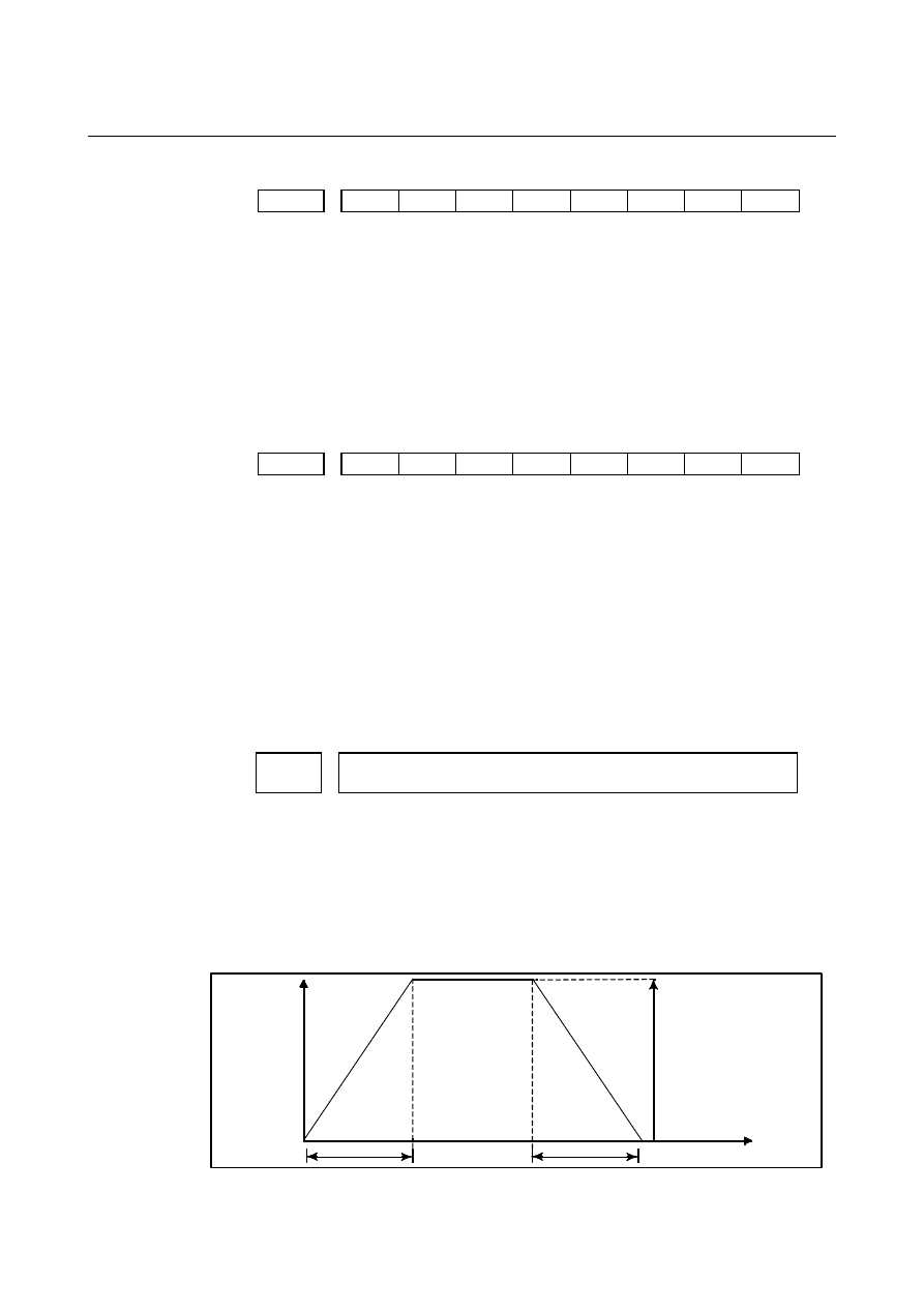
[Example] 
For linear acceleration/deceleration 


Speed


Rapid traverse rate 

(Parameter No. 1420)

Time


T

T


T : Setting of parameter No. 1620 
 

B-63944EN/03

 APPENDIX 

A.PARAMETERS


- 2013 - 

For bell-shaped acceleration/deceleration 


Speed


Rapid traverse rate

(Parameter No. 1420)


Time


T

1


T

T

2

T

2

T

2


T

1


T

1  

: Setting of parameter No. 1620 

T

2  

: Setting of parameter No. 1621 

 (However, 

T

 T

2

 must be satisfied.) 

Total acceleration (deceleration) time  : T

1

 + T

2


Time for linear portion 


: T

1

T

2


Time for curve portion 


: T

2


×

 2 


1622 


Time constant of acceleration/deceleration in cutting feed for each axis 


[Input type]  Parameter input 


[Data type]  Word axis 


[Unit of data]  msec 

  [Valid data range]  0 to 4000 

Set the time constant used for exponential acceleration/deceleration in 
cutting feed, bell-shaped acceleration/deceleration after interpolation 
or linear acceleration/deceleration after interpolation in cutting feed 
for each axis. Which type to use is selected with bits 1(CTBx) and 
0(CTLx) of parameter No.1610. Except for special applications, the 
same time constant must be set for all axes in this parameter. If the 
time constants set for the axes differ from each other, proper straight 
lines and arcs cannot be obtained. 
 

1624 


Time constant of acceleration/deceleration in jog feed for each axis. 


[Input type]  Parameter input 


[Data type]  Word axis 


[Unit of data]  msec 

  [Valid data range]  0 to 4000 

Set the time constant used for acceleration/deceleration in jog feed for 
each axis. 
 

A.PARAMETERS

 APPENDIX 

B-63944EN/03


- 2014 - 

1660 


Maximum allowable acceleration rate in acceleration/deceleration before 

interpolation for each axis 


[Input type]  Parameter input 


[Data type]  Real axis 


[Unit of data]  mm/sec

2

, inch/sec

2

, degree/sec

2

 (machine unit) 


[Minimum unit of data]  Depend on the increment system of the applied axis 

  [Valid data range]  Refer to the standard parameter setting table (D) 

(When the machine system is metric system, 0.0 to +100000.0. When 
the machine system is inch system, machine, 0.0 to +10000.0.) 
Set a maximum allowable acceleration rate in acceleration/ 
deceleration before interpolation for each axis. 
If a value greater than 100000.0 is set, the value is clamped to 
100000.0. 
If 0 is set, the specification of 100000.0 is assumed. If 0 is set for all 
axes, however, acceleration/deceleration before interpolation is not 
performed. 


If a maximum allowable acceleration rate set for one axis is greater 
than a maximum allowable acceleration rate set for another axis by a 
factor or 2 or more, the feedrate at a corner where the direction of 
travel abruptly changes can decrease temporarily. 
 

1671 


Maximum allowable acceleration rate in acceleration/deceleration before 

interpolation for linear rapid traverse for each axis, or maximum allowable 

reference acceleration rate in optimum torque acceleration/deceleration 


[Input type]  Parameter input 


[Data type]  Real axis 


[Unit of data]  mm/sec

2

, inch/sec

2

, degree/sec

2

 (machine unit) 


[Minimum unit of data]  Depend on the increment system of the applied axis 

  [Valid data range]  Refer to the standard parameter setting table (D) 

(When the machine system is metric system, 0.0 to +100000.0. When 
the machine system is inch system, machine, 0.0 to +10000.0.) 
(1)  Set a maximum allowable acceleration rate in acceleration/ 

deceleration before interpolation for linear rapid traverse. 


If a value greater than 100000.0, the value is clamped to 
100000.0. 


If 0 is set, the specification of the following is assumed: 


  1000.0 mm/sec

2


  100.0 inch/sec

2


  100.0 degrees/sec

2


If 0 is specified for all axes, however, acceleration/deceleration 
before interpolation is not performed. 

(2)  Maximum allowable reference acceleration rate in optimum 

torque acceleration/deceleration 


B-63944EN/03

 APPENDIX 

A.PARAMETERS


- 2015 - 

1672 


Acceleration change time of bell-shaped acceleration/deceleration before 

interpolation for linear rapid traverse, or acceleration change time of 

bell-shaped acceleration/deceleration in optimum torque 

acceleration/deceleration 


[Input type]  Parameter input 


[Data type]  2-word path 


[Unit of data]  msec 

  [Valid data range]  0 to 200 

(1)  Set an acceleration change time of bell-shaped acceleration/ 

deceleration for linear rapid traverse (time for changing from the 
state of constant feedrate (A) to the state of constant 
acceleration/deceleration (C) at the acceleration rate calculated 
from the acceleration rate set in parameter No. 1671: time of (B) 
in the figure below). 

(2)  Set an acceleration change time of bell-shaped acceleration/ 

deceleration in optimum torque acceleration/deceleration (time 
for changing from the state of constant feedrate (A) to the state of 
acceleration/deceleration (C) at the acceleration rate calculated 
from optimum torque acceleration/deceleration: time of (B) in 
the figure below). 


F eedrate in tangent direction 

M axim um   acceleration rate not 
exceeding m axim um   allow able 
acceleration rate  set by param eter 
N o. 1671 for  each  axis is 
autom atically calculated. 

T im e set  by param eter N o. 1672 

(A )

(B )

(B )

(B )

(B ) 

(A )

(A ) 

(C )

(C )


A.PARAMETERS

 APPENDIX 

B-63944EN/03


- 2016 - 

1710 

  Minimum deceleration ratio (MDR) for inner circular cutting feedrate change 

by automatic corner override 


[Input type]  Parameter input 


[Data type]  Byte path 


[Unit of data]  % 

  [Valid data range]  0 to 100 

Set a minimum deceleration ratio (MDR) for an inner circular cutting 
feedrate change by automatic corner override. 


In the case of circular cutting offset inward, the actual feedrate is 
determined by a specified feedrate (F) as follows: 


Thus, the feedrate along the programmed path satisfies the specified 
value of F. 


Programmed path

Tool center path 

Rc

Rp


However, if Rc is too small when compared with Rp, Rc/Rp   0 
results to stop the tool. So, a minimum deceleration ratio (MDR) is set, 
and the feedrate of the tool is set to F

×

(MDR) when Rc/Rp 

 MDR. 


1711 


Inner determination angle (

θ

p) for inner corner override 


[Input type]  Parameter input 


[Data type]  Real path 


[Unit of data]  deg 


[Minimum unit of data]  Depend on the increment system of the reference axis 

  [Valid data range]  2 to 178 

Set an inner determination angle for inner corner override in automatic 
corner overriding. 
 

1712 


Override value for inner corner override 


[Input type]  Parameter input 


[Data type]  Byte path 


[Unit of data]  % 

  [Valid data range]  1 to 100 

Set an inner corner override value in automatic corner overriding. 
 

Rp

Rc

F

×

Rc:Radius of tool center 

path 

Rp:Programmed radius

B-63944EN/03

 APPENDIX 

A.PARAMETERS


- 2017 - 

1713 


Start distance (Le) for inner corner override 


[Input type]  Setting input 


[Data type]  Real path 


[Unit of data]  mm, inch (input unit) 


[Minimum unit of data]  Depend on the increment system of the reference axis 

 [Valid data range]  9 digit of minimum unit of data (refer to standard parameter setting 

table (A))   
(When the increment system is IS-B, -999999.999 to +999999.999) 
Set a start distance for inner corner override in automatic corner 
overriding. 
 

1714 


End distance (Ls) for inner corner override 


[Input type]  Setting input 


[Data type]  Real path 


[Unit of data]  mm, inch (input unit) 


[Minimum unit of data]  Depend on the increment system of the reference axis 

 [Valid data range]  9 digit of minimum unit of data (refer to standard parameter setting 

table (A))   
(When the increment system is IS-B, -999999.999 to +999999.999) 
Set an end distance for inner corner override in automatic corner 
overriding. 
 
When 

θ


θ

p, an inner corner is assumed. (Parameter No. 1711 is used 

to set 

θ

p.) 

When a corner is determined to be an inner corner, an override is 
applied to the feedrate in the range of Le in the previous block from 
the intersection of the corner and in the range of Ls in the next block 
from the intersection of the corner. 
Distances Le and Ls represent linear distances from the intersection of 
a corner to points on the tool center path. 
Le and Ls are set in parameter No. 1713 and No. 1714. 

Programmed path 

Tool center path 

An override is applied to the range from point a to point b. 


A.PARAMETERS

 APPENDIX 

B-63944EN/03


- 2018 - 

1732 


Minimum allowable feedrate for the deceleration function based on 

acceleration in circular interpolation 


[Input type]  Parameter input 


[Data type]  Real path 


[Unit of data]  mm/min, inch/min, degree/min (machine unit) 


[Minimum unit of data]  Depend on the increment system of the reference axis 

  [Valid data range]  Refer to the standard parameter setting table (C) 

(When the increment system is IS-B, 0.0 to +999000.0) 
With the deceleration function based on acceleration in circular 
interpolation, an optimum feedrate is automatically calculated so that 
acceleration produced by changing the move direction in circular 
interpolation does not exceed the maximum allowable acceleration 
rate specified in parameter No. 1735. 
If the radius of an arc is very small, a calculated feedrate may become 
too low. 
In such a case, the feedrate is prevented from decreasing below the 
value specified in this parameter. 


NOTE 


During involute interpolation, the minimum 
allowable feedrate of "clamping of acceleration 
near a basic circle" in involute interpolation 
automatic feedrate control is used. 


1735 

  Maximum allowable acceleration rate for the deceleration function based on 

acceleration in circular interpolation for each axis 


[Input type]  Parameter input 


[Data type]  Real axis 


[Unit of data]  mm/sec

2

, inch/sec

2

, degree/sec

2

 (machine unit) 


[Minimum unit of data]  Depend on the increment system of the applied axis 

  [Valid data range]  Refer to the standard parameter setting table (D) 

(When the machine system is metric system, 0.0 to +100000.0. When 
the machine system is inch system, machine, 0.0 to +10000.0.) 
Set a maximum allowable acceleration rate for the deceleration 
function based on acceleration in circular interpolation. 
Feedrate is controlled so that acceleration produced by changing the 
move direction in circular interpolation does not exceed the value 
specified in this parameter. 
For an axis with 0 set in this parameter, the deceleration function 
based on acceleration is disabled. 
If a different value is set in this parameter for each axis, a feedrate is 
determined from the smaller of the acceleration rates specified for the 
two circular axes. 


NOTE 


During involute interpolation, the minimum 
allowable feedrate of "clamping of acceleration 
near a basic circle" in involute interpolation 
automatic feedrate control is used. 


B-63944EN/03

 APPENDIX 

A.PARAMETERS


- 2019 - 

1737 

  Maximum allowable acceleration rate for the deceleration function based on 

acceleration in AI contour control for each axis 


[Input type]  Parameter input 


[Data type]  Real axis 


[Unit of data]  mm/sec

2

, inch/sec

2

, degree/sec

2

 (machine unit) 


[Minimum unit of data]  Depend on the increment system of the applied axis 

  [Valid data range]  Refer to the standard parameter setting table (D) 

(When the machine system is metric system, 0.0 to +100000.0. When 
the machine system is inch system, machine, 0.0 to +10000.0.) 
Set a maximum allowable acceleration rate produced by changing the 
tool move direction. 
For an axis with 0 set in this parameter, the deceleration function 
based on acceleration is disabled. If 0 is set for all axes, the 
deceleration function based on acceleration is not performed. 
In circular interpolation, however, the deceleration function based on 
feedrate control using acceleration in circular interpolation (parameter 
No. 1735) is enabled. 
 

1738 


Minimum allowable feedrate for the deceleration function based on 

acceleration in AI contour control 


[Input type]  Parameter input 


[Data type]  Real path 


[Unit of data]  mm/min, inch/min, degree/min (machine unit) 


[Minimum unit of data]  Depend on the increment system of the reference axis 

  [Valid data range]  Refer to the standard parameter setting table (C) 

(When the increment system is IS-B, 0.0 to +999000.0) 
With the deceleration function based on acceleration in AI contour 
control, a feedrate most suitable for a desired figure is automatically 
calculated. 
Depending on the figure, however, the calculated feedrate may 
become too low. 
In such a case, the feedrate is prevented from decreasing below the 
value specified in this parameter. 
If overriding using the deceleration function based on cutting load is 
enabled, a feedrate lower than the minimum allowable feedrate may 
be used. 
 

1769 

  Time constant for acceleration/deceleration after cutting feed interpolation in 

the acceleration/deceleration before interpolation mode 


[Input type]  Parameter input 


[Data type]  Word axis 


[Unit of data]  msec 

  [Valid data range]  0 to 4000 

In the acceleration/deceleration before interpolation mode as in AI 
contour control, not the ordinary time constant (parameter No. 1622) 
but the value of this parameter is used. 
Be sure to specify the same time constant value for all axes except for 
a special application. If different values are set, correct linear and 
circular figures cannot be obtained. 


Content      ..     255      256      257      258     ..