FANUC Series 30i/300i/300is-MODEL A. Machining Center System. User's manual - page 245
 

  Index      Manuals     FANUC Series 30i/300i/300is-MODEL A. Machining Center System. User's manual (B-63944EN/03)


Search            copyright infringement  


Content      ..     243      244      245      246     ..


FANUC Series 30i/300i/300is-MODEL A. Machining Center System. User's manual - page 245


13

.

GRAPHIC

 FUNCTION

 OPERATION 

B-63944EN/03


- 1916 - 


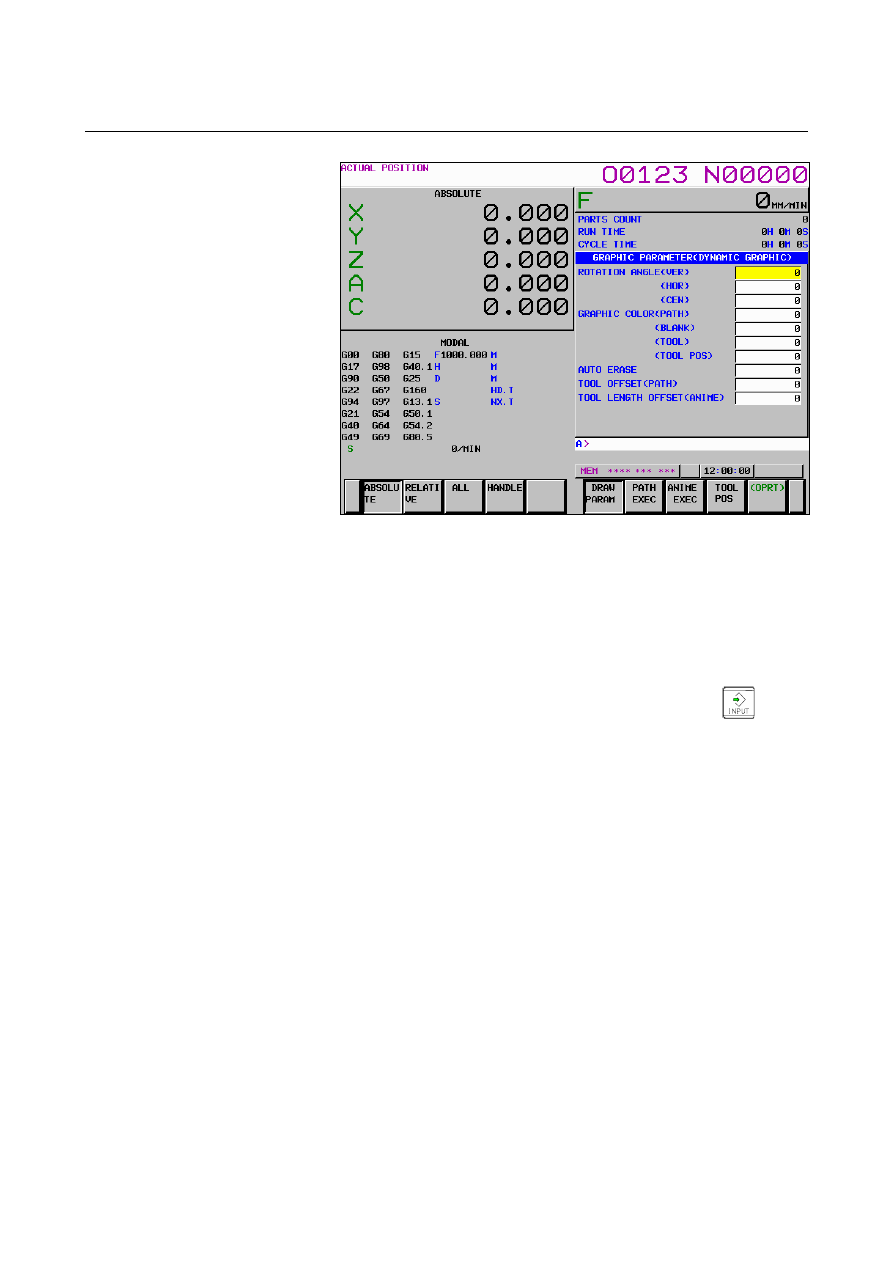
Fig. 13.2.1.1 (b)    GRAPHIC PARAMETER screen (second page) 


Two screens are used for the GRAPHIC PARAMETER screen. 
Use the MDI page keys to switch between the screens for display 
of a desired setting item. 


Move the cursor to a desired setting item with the MDI cursor 
keys then key in a desired value with the numeric keys. 


For direct input of the value set in step 3, press the 

 key or 

the [INPUT] soft key. 
For incremental input of the value set in step 3, press the 
[+INPUT] soft key. 
 

For each setting item, see the explanation. 
 

B-63944EN/03

 OPERATION 

13.GRAPHIC FUNCTION


- 1917 - 

Explanation 

The setting items on the GRAPHIC PARAMETER screen are 
described below. 
 

  - Graphic coordinate system 

Select a graphic coordinate system for drawing from the following and 
set its number. 


Y

X

Setting=0 (XY)

Z

Y

Setting=1 (ZY) 

Y

Setting=2 (YZ)

Z

X

Setting =3 (XZ) 

Setting=5 (XYZ)

Z

X

Y

Setting=6 (YXZ)

Z

Y

X

X

Z

Setting=4 (ZX) 

Setting=7 (YZX)

Y Z


Fig. 13.2.1.1 (c)    Graphic coordinate system 


 - Scale 

Set the scale factor for drawing in the range of 0.01 to 100.00 (times). 
With a small scale factor, it is possible to draw within a wide range. 
With a large scale factor, it is possible to draw in the vicinity of the 
graphic center being enlarged.


  - Graphic range center 

To specify the center coordinates of a graphic range, set a coordinate 
on each axis in the workpiece coordinate system of the program 
executed for drawing. 
 

NOTE 


Set a coordinate on each axis in the machine 
coordinate system in case of bit 3 (BGM) of 
parameter No.11329=1. 


13

.

GRAPHIC

 FUNCTION

 OPERATION 

B-63944EN/03


- 1918 - 

 - Blank figure 

With a drawing program, set the figure, position, and dimensions of a 
blank to be machined. 
The graphic range where the blank figure is included in the drawing 
area is automatically decided by the value set here. 
 

NOTE 

1  With a lathe system, no rectangular parallelepiped 

can be set. 

2  With a lathe system, the Y-axis, one of the basic 

three axes, may not exist.    In such a case, the 
Y-axis for the reference position of a blank need 
not be set. 

3  When a figure or dimension is set, a scale value 

and screen center coordinates are automatically 
set as the initial graphic range values so that the 
blank figure is located within the graphic range on 
the screen.    Until a modification is made to the 
blank figure, dimension or the setting of the graphic 
coordinate system, the graphic range is determined 
by the set scale and screen center coordinates. 


    Figure 

Select a type of blank figure from the following and set the 
corresponding value: 
 

Setting Figure 

Column or cylinder 

(parallel with the Z-axis) 

1 Rectangular 

parallelepiped 


    Position 

Set the reference position of a blank with coordinates (X,Y,Z) in the 
workpiece coordinate system. 
 

NOTE 


Set the reference position of a blank with 
coordinates (X,Y,Z) in the machine coordinate 
system in case of bit 3 (BGM) of parameter 
No.11329=1. 


B-63944EN/03

 OPERATION 

13.GRAPHIC FUNCTION


- 1919 - 

    Dimensions 

Set the dimensions of each type of blank figure as indicated below. 
 

Type of 

blank figure

Dimension I 

Dimension J 

Dimension K 

Rectangular 

parallelepiped

Length in X-axis 

direction 

Length in Y-axis 

direction 

Length in Z-axis 

direction 

Column 

Diameter of 

column 

Length of 

column 

Cylinder 

Diameter of outer 

circle of cylinder 

Diameter of inner 

circle of cylinder 

Length of 

cylinder 

 
The relationship between the position and dimensions of a blank is 
shown below. 


J

K

: Reference position (X,Y,Z)

I

X

Z

Y

X

Y

J

K


13

.

GRAPHIC

 FUNCTION

 OPERATION 

B-63944EN/03


- 1920 - 

 - Rotation angle 

Set a rotating angle of the graphic coordinate system that centers on 
the graphic range center. The rotating angle is a range of -360°-+360°. 
Set a rotating angle as a reference position (position of the rotating 
angle 0°) on the indicated direction of each graphic coordinate system. 
 

      Vertical plane rotation angle 

Set a rotating angle at the horizontal direction center in front of the 
screen. 
The rotation direction is as follows. 

Rotation center


      Horizontal plane rotation angle 

Set a rotating angle at the vertical direction center in front of the 
screen. 
The rotation direction is as follows. 

Rotation center 


      Screen center rotation angle 

Set a rotating angle at the vertical direction center of the screen plane. 
The rotation direction is as follows. 

Rotation center 


B-63944EN/03

 OPERATION 

13.GRAPHIC FUNCTION


- 1921 - 

 - Graphic color 

Set colors to be used for tool path drawing. 
The colors that can be set are indicated below together with their 
setting values: 

Graphic 

color 

White

Red

Green

Yellow Blue Purple 

Light 

blue

White

Setting 

value 

0 1 2  3 4 5  6 7 


      Path 

Set colors to be used for a drawn tool path. 
 

    Tool position 

Set a graphic cursor color to be used for PATH GRAPHIC (TOOL 
POSITION) screen. 
 

 - Auto erase 

When drawing is started with the [START] soft key from a state 
where drawing is not being executed or is not stopped temporarily, the 
previously drawn path can be erased. 
Setting  0:    The previously drawn path is not erased. 

  1:    The previously drawn path is erased. 


 - Tool offset

Path


For tool path drawing, whether to enable or disable the tool offset 
function (tool length compensation, cutter/tool-noise radius 
compensation) can be selected. 
Setting  0:    The tool offset function is enabled for drawing. 

  1:    The tool offset function is disabled for drawing. 


13

.

GRAPHIC

 FUNCTION

 OPERATION 

B-63944EN/03


- 1922 - 

13.2.1.2 

PATH GRAPHIC screen 

 
The PATH GRAPHIC screen is used to draw a tool path.  The 
following operations can be performed: 


Starting/ending tool path drawing 


Rewind of a drawing target program 


Erasing a drawn tool path   

 
The screen is composed of the following items: 
(1) Drawing 

area 

(2)  Status display of Background operation 
(3)  Program name and sequence number for drawing execution 
(4)  Current coordinates (absolute coordinates) 
(5)  Feedrate and M/S/T/D code instruction information 
(6)  Graphic coordinate system 


Fig. 13.2.1.2 (a)    PATH GRAPHIC screen 


B-63944EN/03

 OPERATION 

13.GRAPHIC FUNCTION


- 1923 - 

Path Graphic Screen Procedure 

Procedure 

1 Press 

the 

function 

key   (or 

  when a small MDI unit 

is used) to display the GRAPHIC PARAMETER (DYNAMIC 
GRAPHIC) screen. 

 
2  Press the [PATH EXEC] soft key.  The PATH GRAPHIC 

screen is displayed. 


Fig. 13.2.1.2 (b)    PATH GRAPHIC screen 

 
3  Press the [(OPRT)] soft key.  The soft keys for tool path 

drawing are displayed. 


Fig. 13.2.1.2 (c)    PATH GRAPHIC screen (operation) 


Press the continuous menu key 

  to display the soft keys for 

enlarging/reducing/moving the graphic range. 


Fig. 13.2.1.2 (d)    PATH GRAPHIC screen 

  (enlarging/reducing/moving the graphic range) 


Press the [COORDINATES] soft key to display the soft keys for 
changing the graphic coordinate system. 


Fig. 13.2.1.2 (e)    PATH GRAPHIC screen 

  (changing the graphic coordinate system) 


Content      ..     243      244      245      246     ..